WO2014103252A1 - 電子写真用定着部材、定着装置及び電子写真画像形成装置 - Google Patents
電子写真用定着部材、定着装置及び電子写真画像形成装置 Download PDFInfo
- Publication number
- WO2014103252A1 WO2014103252A1 PCT/JP2013/007440 JP2013007440W WO2014103252A1 WO 2014103252 A1 WO2014103252 A1 WO 2014103252A1 JP 2013007440 W JP2013007440 W JP 2013007440W WO 2014103252 A1 WO2014103252 A1 WO 2014103252A1
- Authority
- WO
- WIPO (PCT)
- Prior art keywords
- elastic layer
- fixing member
- fixing
- heat
- inorganic filler
- Prior art date
- Legal status (The legal status is an assumption and is not a legal conclusion. Google has not performed a legal analysis and makes no representation as to the accuracy of the status listed.)
- Ceased
Links
Images





Classifications
-
- G—PHYSICS
- G03—PHOTOGRAPHY; CINEMATOGRAPHY; ANALOGOUS TECHNIQUES USING WAVES OTHER THAN OPTICAL WAVES; ELECTROGRAPHY; HOLOGRAPHY
- G03G—ELECTROGRAPHY; ELECTROPHOTOGRAPHY; MAGNETOGRAPHY
- G03G15/00—Apparatus for electrographic processes using a charge pattern
- G03G15/20—Apparatus for electrographic processes using a charge pattern for fixing, e.g. by using heat
- G03G15/2003—Apparatus for electrographic processes using a charge pattern for fixing, e.g. by using heat using heat
- G03G15/2014—Apparatus for electrographic processes using a charge pattern for fixing, e.g. by using heat using heat using contact heat
- G03G15/2053—Structural details of heat elements, e.g. structure of roller or belt, eddy current, induction heating
- G03G15/2057—Structural details of heat elements, e.g. structure of roller or belt, eddy current, induction heating relating to the chemical composition of the heat element and layers thereof
-
- G—PHYSICS
- G03—PHOTOGRAPHY; CINEMATOGRAPHY; ANALOGOUS TECHNIQUES USING WAVES OTHER THAN OPTICAL WAVES; ELECTROGRAPHY; HOLOGRAPHY
- G03G—ELECTROGRAPHY; ELECTROPHOTOGRAPHY; MAGNETOGRAPHY
- G03G2215/00—Apparatus for electrophotographic processes
- G03G2215/20—Details of the fixing device or porcess
- G03G2215/2003—Structural features of the fixing device
- G03G2215/2016—Heating belt
- G03G2215/2035—Heating belt the fixing nip having a stationary belt support member opposing a pressure member
Definitions
- the present invention relates to a fixing member for electrophotography.
- the present invention also relates to a fixing device and an electrophotographic image forming apparatus using the same.
- a heat fixing apparatus used in an electrophotographic system such as a laser printer or a copying machine
- a pair of heated rollers and rollers, a film and a roller, a belt and a roller, and a belt and a belt are pressed against each other.
- a recording material holding an image with unfixed toner is introduced into a pressure contact portion (fixing nip) formed between the rotating bodies and heated to melt the toner, and to a recording material such as paper.
- the image is fixed.
- a rotating body that contacts an unfixed toner image held on a recording material is referred to as a fixing member, and is referred to as a fixing roller, a fixing film, or a fixing belt depending on the form.
- covered the release layer which consists of a fluororesin through the silicone rubber elastic layer which has heat resistance, and the silicone rubber adhesive on the base material formed with the metal or heat resistant resin.
- the fixing member having the above-described configuration can wrap and melt the toner image without excessive crushing in the fixing nip by utilizing the excellent elastic deformation of the silicone rubber elastic layer.
- Patent Document 1 discloses a configuration in which a high heat capacity substance is mixed in a part of the fixing member to ensure a large heat capacity of the fixing member and to increase the amount of heat supplied to the recording material. Accordingly, a large amount of heat can be accumulated in the fixing member, which is effective for power saving and speedup.
- Patent Document 2 proposes a fixing belt in which the elastic layer contains a filler and carbon nanotubes to improve the thermal conductivity of the elastic layer.
- the thermal conductivity and the elasticity can be improved by controlling the blending amount of the filler in the elastic layer and the blending amount of the carbon nanotubes.
- JP 2004-45851 A JP 2010-92008 JP
- the fixing process thermal energy is supplied to the recording material and the toner at the fixing nip portion formed between the fixing member in contact with the unfixed toner and the pressure member in contact with the fixing member. Is done. As a result, the toner is melted and cooled and solidified after passing through the fixing nip, whereby the toner is fixed on the recording material and a fixed image is formed.
- the fixing nip passage time (dwell time) is shortened, so it is necessary to supply heat to the recording material and toner in a shorter time. is there.
- the present inventors discussed the heat supply from the fixing member to the recording material, and considered that the introduction of the concept of heat permeability is effective for the heat supply capability from the high temperature material to the low temperature material. That is, the thermal permeability is used as an index of the ability to give or take away heat when a certain substance comes into contact with an object having a different temperature.
- This heat permeability b is expressed by the following formula (1 ′).
- b ( ⁇ ⁇ C p ⁇ ⁇ ) 0.5 (1 ′)
- ⁇ represents thermal conductivity
- C p represents constant pressure specific heat
- ⁇ represents density.
- the fixing member in order to give thermal energy to the recording material and the toner in a shorter dwell time, it is necessary to design the heat penetration rate high from the viewpoint of improving the heat supply capability. Therefore, it is necessary to improve both thermal conductivity and volumetric heat capacity without sacrificing each other.
- the surface of the fixing member needs to follow the unevenness of the paper when the paper passes through the fixing nip portion.
- heat can be transferred by directly contacting the toner in the concave portion, and an effect of preventing occurrence of uneven melting of the toner can be obtained.
- it is necessary to ensure flexibility by designing the elastic layer to have a lower hardness.
- the heat supply capability of the fixing member can be improved by designing the heat permeability of the elastic layer, that is, the thermal conductivity and the volumetric heat capacity high.
- These thermophysical properties can be improved by increasing the filler content in the elastic layer.
- an increase in the amount of filler added in the region also increases the hardness of the elastic layer.
- considering the further speeding up and downsizing of the future electrophotographic image forming process and the diversification of the usage environment it is necessary to have a configuration that can solve the above two conflicting problems at a higher level than before. It becomes.
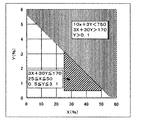
- FIG. 10 shows regions defined by these formulas in a graph in which the vertical axis represents Y% and the horizontal axis represents X%.
- the invention which concerns on patent document 2 is aiming at coexistence of the raise suppression of hardness, and the improvement of thermal conductivity by controlling the addition amount of a filler and a carbon nanotube.
- the fixing member that is designed to have a high thermal conductivity based on the disclosure of Patent Document 2 is impaired in the ability to follow the unevenness of the paper, that is, the flexibility. I found a problem.
- the blending amount of the filler and the carbon nanotube in the elastic layer is 3X + 30Y ⁇ 170. That is, the conclusion that it is necessary to make it in the shaded area in FIG.
- the amount of filler and carbon nanotube in the elastic layer is kept in the shaded area in FIG. It is necessary to improve performance.
- an object of the present invention is to provide a fixing member having an elastic layer that is flexible and has a high thermal permeability.
- Another object of the present invention is to provide a fixing device and an electrophotographic image forming apparatus capable of satisfactorily fixing toner even on a recording medium having low smoothness and large irregularities.
- the present inventors have repeatedly studied to achieve a higher level of compatibility between the flexibility of the fixing member and high heat transfer performance. As a result, it has been found that it is possible to obtain a fixing member having an elastic layer that secures a high heat permeability and flexibility, which may not have been achieved by the conventional configuration.
- the present invention is based on such knowledge, and solves the problem by the following means.
- a fixing member for electrophotography having a base material, an elastic layer and a release layer, wherein the elastic layer contains silicone rubber, an inorganic filler, and vapor grown carbon fiber,
- the volume proportion of the inorganic filler in the elastic layer is X (%) and the volume proportion of the vapor grown carbon fiber is Y (%)
- the following formula (1), formula (2) and formula A fixing member that satisfies the relationship 3) and has an aspect ratio that is a ratio of the fiber length to the fiber diameter of the vapor grown carbon fiber is 50 or more is provided: 3X + 30Y ⁇ 170 (1) 25 ⁇ X ⁇ 50 (2) 0.5 ⁇ Y ⁇ 3.1 (3).
- a fixing device comprising the above-described fixing member and a heating means for the fixing member.
- an electrophotographic image forming apparatus provided with the fixing device described above.
- the present invention it is possible to obtain a fixing member having an elastic layer having a high heat permeability while ensuring followability of the member surface to a recording material having large irregularities such as recycled paper.
- the present invention it is possible to obtain a fixing device that can stably apply sufficient heat to the toner and the recording material while suppressing the uneven melting of the toner.
- an electrophotographic image forming apparatus capable of stably providing a high-definition image on various recording materials can be obtained.
- FIG. 3 is a schematic cross-sectional view of the vicinity of the surface of the fixing member according to the present invention. It is explanatory drawing of an example of the process of forming the elastic layer of the fixing member which concerns on this invention. It is explanatory drawing of an example of the process of forming the release layer of the fixing member which concerns on this invention. It is explanatory drawing of an example of the process of forming the release layer of the fixing member which concerns on this invention. 1 is a cross-sectional view of an example of a fixing device according to the present invention. 1 is a cross-sectional view of an example of a fixing device according to the present invention.
- FIG. 1 is a cross-sectional view of an example of an electrophotographic image forming apparatus according to the present invention. It is an example of the scanning electron microscope (SEM) photograph of the elastic layer material which concerns on this invention. It is a graph which the numerical formula which concerns on invention of patent document 2 represents.
- SEM scanning electron microscope
- the fixing member according to the present invention will be described below based on a specific configuration.
- FIG. 1 is a schematic cross-sectional schematic view showing one embodiment of a fixing member for electrophotography according to the present invention, wherein 1 is a fixing member (fixing belt) having a belt shape, and 2 is a roller-shaped fixing member (fixing). Roller).
- 1 is a fixing member (fixing belt) having a belt shape
- 2 is a roller-shaped fixing member (fixing). Roller).
- a fixing belt when the base material itself is deformed to form a fixing nip and used.
- the fixing roller is used.
- 3 is a base material
- 4 is an elastic layer covering the peripheral surface of the base material 3
- 6 is a release layer.
- the release layer 6 may be fixed to the peripheral surface of the elastic layer 4 by the adhesive layer 5.
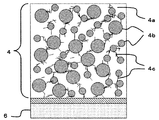
- FIG. 2 is an enlarged view of the layer structure near the surface of the fixing member and schematically showing a cross section.
- 4 is an elastic layer
- 4a is a silicone rubber as a base material
- 4b is an inorganic filler
- 4c is a vapor grown carbon fiber.
- vapor grown carbon fibers 4 c entangled with each other are present in the elastic layer 4 so as to bridge between the inorganic fillers 4 b.
- the heat transfer path is formed by bridging the inorganic fillers 4b with the vapor grown carbon fiber 4c. Therefore, the total amount (volume ratio) of the filler that increases the heat conduction and hardness can be suppressed, and a fixing member having excellent heat supply capability can be obtained without causing an excessive increase in hardness.
- Reference numeral 5 indicates an adhesive layer, and reference numeral 6 indicates a release layer. The method for forming these layers will also be described in detail later.
- Base Material for example, a metal or alloy such as aluminum, iron, stainless steel, or nickel, or a heat resistant resin such as polyimide is used.
- a cored bar is used for the base material 3.
- the material of the core metal include metals and alloys such as aluminum, iron, and stainless steel.
- examples of the substrate 3 include a heat-resistant resin belt made of an electroformed nickel sleeve, a stainless sleeve, polyimide, or the like.
- a layer (not shown) for imparting functions such as wear resistance and heat insulation may be further provided on the inner surface of the belt.
- a layer (not shown) for imparting a function such as adhesion to the elastic layer may be further provided on the outer surface.
- the elastic layer 4 functions as a layer that supports the fixing member with elasticity having flexibility to follow the irregularities of the paper fibers without crushing the toner during fixing.
- the elastic layer 4 is preferably made of a heat-resistant rubber such as silicone rubber or fluorine rubber as a base material, and more preferably an addition-curable silicone rubber is cured.
- Addition-curing type silicone rubber in FIG. 2, 4a constitutes an addition-curing type silicone rubber.
- addition-curable silicone rubber contains an organopolysiloxane having an unsaturated aliphatic group, an organopolysiloxane having an active hydrogen bonded to silicon, and a platinum compound as a crosslinking catalyst.
- organopolysiloxanes having unsaturated aliphatic groups include: A linear organopolysiloxane in which both molecular ends are represented by (R 1 ) 2 R 2 SiO 1/2 and intermediate units are represented by (R 1 ) 2 SiO and R 1 R 2 SiO; A branched organopolysiloxane containing R 1 SiO 3/2 to SiO 4/2 in the intermediate unit.
- R 1 represents a monovalent unsubstituted or substituted hydrocarbon group bonded to a silicon atom and not containing an aliphatic unsaturated group. Specific examples include the following.
- alkyl group for example, methyl group, ethyl group, propyl group, butyl group, pentyl group, hexyl group, etc.
- ⁇ Aryl group phenyl group etc.
- -Substituted hydrocarbon groups for example, chloromethyl group, 3-chloropropyl group, 3,3,3-trifluoropropyl group, 3-cyanopropyl group, 3-methoxypropyl group, etc.
- R 1 is a methyl group, and particularly preferably all of R 1 is a methyl group.
- R 2 represents an unsaturated aliphatic group bonded to a silicon atom, and examples thereof include a vinyl group, an allyl group, a 3-butenyl group, a 4-pentenyl group, and a 5-hexenyl group, which are easy to synthesize and handle.
- a vinyl group is preferable because a crosslinking reaction is also easily performed.
- the organopolysiloxane having active hydrogen bonded to silicon is a crosslinking agent that forms a crosslinked structure by reaction with an alkenyl group of an organopolysiloxane component having an unsaturated aliphatic group by the catalytic action of a platinum compound.
- the number of hydrogen atoms bonded to the silicon atom is an average of more than 3 in one molecule.
- Examples of the organic group bonded to the silicon atom include an unsubstituted or substituted monovalent hydrocarbon group having the same range as R 1 of the organopolysiloxane component having an unsaturated aliphatic group. In particular, a methyl group is preferred because it is easy to synthesize and handle.
- the molecular weight of the organopolysiloxane having active hydrogen bonded to silicon is not particularly limited.
- the viscosity at 25 ° C. of the organopolysiloxane is preferably 10 mm 2 / s or more 100,000 mm 2 / s or less, more preferably in the range of less than 15 mm 2 / s or more 1,000mm 2 / s. Limiting the viscosity to these ranges does not cause volatilization during storage and the desired degree of cross-linking or physical properties of the molded product cannot be obtained, and it is easy to synthesize and handle, and is easily and uniformly dispersed in the system. It is because it can be made.
- the siloxane skeleton may be linear, branched, or cyclic, and a mixture thereof may be used. In particular, a straight chain is preferable because of easy synthesis.
- the Si—H bond may be present in any siloxane unit in the molecule, but at least a part of it is preferably present in the siloxane unit at the molecular end such as (R 1 ) 2 HSiO 1/2 unit. .
- the addition-curable silicone rubber preferably has an unsaturated aliphatic group content of 0.1 mol% or more and 2.0 mol% or less with respect to 1 mol of silicon atoms. In particular, 0.2 mol% or more and 1.0 mol% or less are preferable.
- the elastic layer 4 contains a filler for improving the heat transfer characteristics of the fixing member and imparting reinforcement, heat resistance, workability, conductivity and the like.
- the elastic layer concerning this invention contains an inorganic filler and a vapor growth method carbon fiber as a filler.
- the inorganic filler preferably has a high thermal conductivity and a high volumetric heat capacity.
- Specific examples include inorganic substances, particularly metals and metal compounds.
- inorganic fillers used for the purpose of improving heat transfer characteristics are listed below. In addition, these can be used individually or in mixture of 2 or more types.
- -Silicon carbide Silicon nitride; Boron nitride; Aluminum nitride; Alumina; Zinc oxide; Magnesium oxide; Silica; Copper; Aluminum; Silver; Iron; Nickel;
- an inorganic filler having a volumetric heat capacity of 3.0 [MJ / m 3 ⁇ K] or more is preferably used.
- specific examples of such inorganic fillers include fillers mainly composed of alumina, magnesium oxide, zinc oxide, iron, copper, and nickel. These volumetric heat capacities are shown below.
- the average particle size of the inorganic filler mentioned above is preferably 1 to 50 ⁇ m, particularly 5 to 30 ⁇ m from the viewpoint of dispersibility in the material mixture for forming the elastic layer.
- the average particle diameter of the inorganic filler in the elastic layer is determined by a flow type particle image analyzer (trade name: FPIA-3000; manufactured by Sysmex Corporation). Specifically, a sample cut out from the elastic layer is placed in a porcelain crucible and heated to 1000 ° C. in a nitrogen atmosphere to ash and remove the rubber component. At this stage, the inorganic filler and vapor grown carbon fibers contained in the sample are present in the crucible. Next, the crucible is heated to 1000 ° C.
- the equal area circle of 1000 inorganic fillers is calculated
- shapes such as spherical shape, a grinding
- the contact area with the elastic layer in the elastic layer is relatively
- an inorganic filler having a shape that can be reduced to a very small value is preferably used. Specific examples of such shapes include spherical inorganic fillers.
- Lmax Lmin
- the ratio is 1.
- the arithmetic average value of the above (Lmax) / (Lmin) for 1,000 high-purity true spherical alumina (trade name: Arnabeads CB-A25BC) particles used in Examples described later was 1.1.
- the elastic layer 4 includes a vapor growth carbon fiber (Vapor Grown carbon fiber) as a filler from the viewpoint of ensuring thermal conductivity in addition to the inorganic filler described above. Contains Carbon Fiber).
- 4c is a vapor grown carbon fiber.
- Vapor-grown carbon fibers are obtained by using hydrocarbons and hydrogen as raw materials, causing a thermal decomposition reaction in the gas phase in a heating furnace, and growing catalyst fine particles in the form of fibers.
- the fiber diameter and fiber length are controlled by the type and size / composition of the raw material and the catalyst, the reaction temperature / atmospheric pressure, and the time, and a product in which the graphite structure is further developed by heat treatment after the reaction is known.
- the radial direction of the fiber has a multilayer structure, and has a shape in which graphite structures are laminated in a cylindrical shape. In general, the average fiber diameter is 80 to 200 nm and the average fiber length is 5 to 15 ⁇ m.
- the average fiber diameter and average fiber length of the vapor grown carbon fiber in the elastic layer are determined by the following method. That is, a predetermined amount (for example, about 10 g) of a sample is cut out from the elastic layer using a razor or the like. This is put in a porcelain crucible and heated at 600 ° C. for about 1 hour in a nitrogen atmosphere to incinerate and remove organic components such as resin and rubber in the elastic layer. In the firing in a nitrogen atmosphere, the carbon fibers are not decomposed and remain as residual components in the crucible. Randomly, 1000 vapor-grown carbon fibers in the residual component were selected and observed at a magnification of 30,000 times using a scanning electron microscope (trade name: JSM-5910V, manufactured by JEOL Ltd.).
- the fiber length and the fiber diameter at the fiber end were measured. And let the arithmetic mean value of the fiber length and fiber diameter of each vapor-grown carbon fiber be the average fiber length and average fiber diameter of the vapor-grown carbon fiber.
- Vapor grown carbon fiber has a very high thermal conductivity of about 1200 W / (m ⁇ K) in the longitudinal direction of the fiber. Therefore, the heat flow path can be efficiently formed in the elastic layer by bridging between the inorganic fillers in the elastic layer. Thereby, the thermal conductivity of the entire elastic layer can be dramatically improved while suppressing the amount of filler in the elastic layer.
- the vapor grown carbon fiber according to the present invention uses vapor grown carbon fiber having an aspect ratio of 50 or more, which is a ratio of fiber length to fiber diameter (fiber length / fiber diameter). This makes it possible to effectively improve the thermal conductivity of the elastic layer while suppressing the content in the elastic layer within a range that does not significantly increase the hardness of the elastic layer.
- the upper limit of the aspect ratio of the vapor grown carbon fiber is not particularly limited, but is about 500 due to restrictions on the production of the vapor grown carbon fiber. Further, the upper limit of the range in which stable production and supply is possible is about 100. Therefore, the preferred aspect ratio of the vapor grown carbon fiber according to the present invention is 50 or more and 100 or less.
- Such vapor-grown carbon fibers are commercially available, for example, as “VGCF” and “VGCF-S” (both trade names, manufactured by Showa Denko KK).
- VGCF has an average fiber diameter of 150 nm, an average fiber length of 9 ⁇ m, and an aspect ratio of 60.
- VGCF-S has an average fiber diameter: 100 nm, an average fiber length: 10 ⁇ m, and an aspect ratio: 100.
- fillers may include carbon black (C) or the like for the purpose of imparting properties such as conductivity.
- volumetric heat capacity of filler can be determined by the product of constant pressure specific heat (C p ) and true density ( ⁇ ), and each value is determined by the following apparatus. be able to.
- C p constant pressure specific heat
- ⁇ true density
- C p Differential scanning calorimeter
- DSC823e Differential scanning calorimeter
- METTLER TOLEDO Differential scanning calorimeter
- ⁇ True density ( ⁇ ) ⁇ ⁇ ⁇ Dry-type automatic densimeter (trade name: Accupic 1330-01; manufactured by Shimadzu Corporation) Specifically, using a 10 cm 3 sample cell, a sample (filler) of about 80% of the cell volume is placed in the sample cell. After measuring the weight of the sample, a cell is set in the measurement unit in the apparatus, helium is used as a measurement gas, and after 10 gas replacements, volume measurement is performed 10 times. The density ( ⁇ ) is calculated from the weight of the sample and the measured volume.
- the thickness of the elastic layer can be designed as appropriate.
- the elastic layer is relatively thin so that, when incorporated in the fixing device, the fixing member can be deformed along the pressure member to ensure a wider nip width. It is preferable to make it thin.
- the thickness of the elastic layer is preferably 100 ⁇ m or more and 500 ⁇ m or less, and particularly preferably 200 ⁇ m or more and 400 ⁇ m or less.
- the base material is a rigid body and the nip width is obtained by deformation of the elastic layer. Therefore, the preferable range of the thickness of the elastic layer is 300 ⁇ m or more and 10 mm or less, particularly 1 mm or more and 5 mm or less.
- the elastic layer is processed by a molding method such as a die coating method, a blade coating method, a nozzle coating method, a ring coating method, or the like, as disclosed in JP-A-2001-62380 and JP-A-2002-213432. Etc. are widely known.
- the elastic layer can be formed by heating and cross-linking the admixture supported on the substrate by these methods.
- FIG. 3 is an example of a process for forming the elastic layer 4 on the substrate 3, and is a schematic diagram for explaining a method using a so-called ring coating method.
- Raw material for forming an elastic layer that is thoroughly mixed and defoamed using a planetary universal mixer, etc., with each filler mixed in an uncrosslinked base material (addition-curing silicone rubber in this example).
- the admixture is filled in the cylinder pump 7 and is applied to the peripheral surface of the base material 3 from the coating head 9 via the feed nozzle 8 of the raw material admixture.
- the base material 3 is moved in the right direction of the drawing at a predetermined speed, whereby the coating film 10 of the raw material mixture can be formed on the peripheral surface of the base material 3.
- the thickness of the coating film can be controlled by the clearance between the coating head 9 and the substrate 3, the supply speed of the raw material mixture, the moving speed of the substrate 3, and the like.
- the coating film 10 of the raw material mixture formed on the base material 3 can be made into the elastic layer 4 by heating for a certain period of time by a heating means such as an electric furnace to advance the crosslinking reaction.
- a fluororesin for example, the resins exemplified below is used.
- PFA Tetrafluoroethylene-perfluoro (alkyl vinyl ether) copolymer
- PTFE polytetrafluoroethylene
- FEP tetrafluoroethylene-hexafluoropropylene copolymer
- PFA is preferable from the viewpoint of moldability and toner releasability.
- Forming means is not particularly limited, but is a method of coating a tube-shaped one, or coating the elastic layer surface directly with a fluororesin fine particle or a dispersion paint in a solvent, followed by drying. ⁇ Methods of melting and baking are known.
- the thickness of the fluororesin release layer is preferably 10 ⁇ m or more and 50 ⁇ m or less, more preferably 30 ⁇ m or less, and is preferably designed to have a thickness of 10% or less of the elastic layer. By setting it as such thickness, the softness
- the fluororesin tube can be prepared by a general method when a hot-melt type fluororesin such as PFA is used.
- a hot-melt type fluororesin pellet is formed into a film or the like using an extrusion molding machine.
- the inner surface of the fluororesin tube can be pretreated with sodium treatment, excimer laser treatment, ammonia treatment, etc. to activate the surface and improve the adhesion.
- FIG. 4 is a schematic diagram of an example of a step of laminating a fluororesin layer on the elastic layer 4 with an adhesive 11 interposed therebetween.
- An adhesive 11 is applied to the surface of the elastic layer 4 described above. The adhesive will be described in detail later.
- an ultraviolet irradiation step may be performed on the surface of the elastic layer 4. Thereby, the penetration of the adhesive 11 into the elastic layer 4 can be suppressed, and an increase in surface hardness due to the reaction with the elastic layer can be suppressed. Further, this ultraviolet irradiation step can be carried out more efficiently by performing it in a heating environment below the heat resistant temperature of the elastic layer.
- the outer surface of the adhesive 11 is covered with a fluororesin tube 12 as the release layer 6 and laminated.
- a fluororesin tube 12 as the release layer 6 and laminated. This is not necessary when the base material 3 is a core metal capable of maintaining its shape, but when a thin base material such as a resin belt or metal sleeve used for a belt-shaped fixing member is used, deformation during processing is prevented. In order to hold it, it is fitted on the core 13 and held.
- the coating method is not particularly limited, and a method of coating an adhesive as a lubricant, a method of expanding and coating a fluororesin tube from the outside, and the like can be used.
- the surplus adhesive remaining between the elastic layer and the release layer is removed by using a means (not shown).
- the thickness of the adhesive layer after being handled is preferably 20 ⁇ m or less. If it is thicker than this, heat transfer characteristics may be deteriorated.
- the fixing member of the present invention can be obtained by heating and curing the adhesive for a predetermined time with a heating means such as an electric furnace, and processing both ends to a desired length as necessary. Can be obtained.
- the adhesive can be appropriately selected depending on the material of the elastic layer and the release layer.
- the adhesive 11 is self-adhesive. It is preferable to use an addition-curable silicone rubber in which an adhesive component is blended. Specifically, it contains an organopolysiloxane having an unsaturated hydrocarbon group represented by a vinyl group, a hydrogen organopolysiloxane, and a platinum compound as a crosslinking catalyst. And it hardens
- a known adhesive can be used.
- self-adhesive components include: -At least one selected from the group consisting of alkenyl groups such as vinyl groups, (meth) acryloxy groups, hydrosilyl groups (SiH groups), epoxy groups, alkoxysilyl groups, carbonyl groups, and phenyl groups, preferably two or more types A silane having a functional group of An organosilicon compound such as a cyclic or linear siloxane having 2 to 30 silicon atoms, preferably 4 to 20 silicon atoms, ⁇ Containing 1 to 4 aromatic rings, preferably 1 to 2 aromatic rings in one molecule, and hydrosilylation of 1 to 4 and preferably 2 to 4 phenylene structures It contains at least one functional group (for example, alkenyl group, (meth) acryloxy group) that can contribute to the addition reaction, preferably 2 or more and 4 or less in one molecule, and may contain an oxygen atom in the molecule.
- Non-silicon-based organic compounds ie, containing no silicon atom in
- a filler can be added within the scope of the gist of the present invention from the viewpoint of adjusting viscosity and ensuring heat resistance.
- fillers include: -Silica, alumina, iron oxide, cerium oxide, cerium hydroxide, carbon black, etc.
- Such addition-curable silicone rubber adhesives are also commercially available and can be easily obtained.
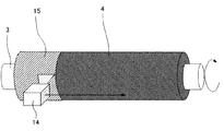
- FIG. 5 shows a schematic diagram of the spray coating method.
- the fluororesin coating forms a so-called dispersion liquid in which fluororesin fine particles are dispersed in a solvent by a surfactant or the like.
- the fluororesin dispersion liquid is also commercially available and can be easily obtained.
- This dispersion liquid is supplied to the spray gun 14 by means (not shown) and sprayed in a mist form by a gas pressure such as air. If necessary, a member having the elastic layer 4 bonded with a primer or the like is disposed at a position facing the spray gun, the member is rotated at a constant speed, and the spray gun 14 is parallel to the axial direction of the substrate 3. Move.
- the coating film 15 of the fluororesin coating can be uniformly formed on the elastic layer surface.
- the member in which the fluororesin coating film 15 is formed is heated to the melting point or more of the fluororesin coating film by using heating means such as an electric furnace, so that the fluororesin release layer can be formed. .
- the electrophotographic heat fixing device has a pair of heated rollers and rollers, a film and a roller, a belt and a roller, and a belt and a belt, which are in pressure contact with each other. In consideration of conditions such as process speed and size, it is appropriately selected.
- a fixing nip N is formed by press-contacting a heated fixing member and a pressure member, and an image is formed with unfixed toner G in the fixing nip width N.
- the material P is nipped and conveyed. As a result, the toner image is heated and pressurized. As a result, the toner image is melted and mixed, and then cooled to fix the toner image on the recording material.
- Patent Document 1 exemplifies a fixing device using a belt-shaped fixing member that is stretched around two rollers.
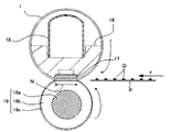
- FIG. 6 shows a schematic cross-sectional view in the transverse direction of an example of a heat fixing device using the belt-shaped electrophotographic fixing member according to the present invention.
- reference numeral 1 denotes a seamless-shaped fixing belt as a fixing member according to an embodiment of the present invention.
- a belt guide member 16 is formed which is molded from a heat-resistant and heat-insulating resin.
- a ceramic heater 17 as a heat source is provided at a position where the belt guide member 16 and the inner surface of the fixing belt 1 are in contact with each other.
- the ceramic heater 17 is fixedly supported by being fitted into a groove formed and provided along the longitudinal direction of the belt guide member 16.
- the ceramic heater 17 is energized by means (not shown) to generate heat.
- the seamless-shaped fixing belt 1 is loosely fitted on the belt guide member 16.
- the pressurizing rigid stay 18 is inserted inside the belt guide 16.
- the elastic pressure roller 19 as a pressure member is formed by providing a silicone rubber elastic layer 19b on a stainless steel core 19a to reduce the surface hardness. Both ends of the cored bar 19a are rotatably supported by the apparatus between a front side (not shown) and a chassis side plate on the back side.
- the elastic pressure roller 19 is covered with a 50 ⁇ m fluororesin tube as the surface layer 19c in order to improve surface properties and releasability.
- a pressing force is applied to the pressurizing rigid stay 18 by contracting a pressurizing spring (not shown) between both ends of the pressurizing rigid stay 18 and a spring receiving member (not shown) on the apparatus chassis side. ing.
- a pressurizing spring (not shown) between both ends of the pressurizing rigid stay 18 and a spring receiving member (not shown) on the apparatus chassis side.
- the lower surface of the ceramic heater 17 disposed on the lower surface of the belt guide member 16 and the upper surface of the pressure member 19 are pressed against each other with the fixing belt 1 interposed therebetween to form a predetermined fixing nip N.
- a recording material P which is an object to be heated and has an image formed with unfixed toner G in the fixing nip N, is nipped and conveyed at a conveyance speed V.
- the toner image is heated and pressurized.
- the toner image is melted and mixed, and then cooled to fix the toner image on the recording material.
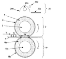
- FIG. 7 shows a schematic cross-sectional view in the transverse direction of an example of a heat fixing device using the roller-shaped fixing member for electrophotography according to the present invention.
- reference numeral 2 denotes a fixing roller as a fixing member according to an embodiment of the present invention.
- the fixing roller 2 has an elastic layer 4 formed on the outer peripheral surface of a cored bar 3 as a base material, and further a release layer 6 formed on the outer side thereof.
- a pressure roller 19 as a pressure member is disposed so as to face the fixing roller 2, and the fixing nip N is formed by pressing the two rollers rotatably by a pressure unit (not shown). ing.
- the external heating unit 20 heats the fixing roller 2 from the outside of the roller in a non-contact manner.
- the external heating unit 20 includes a halogen heater (infrared source) 20a as a heat source and a reflecting mirror (infrared reflecting member) 20b for efficiently using the radiant heat of the halogen heater 20a.
- the halogen heater 20a is disposed to face the fixing roller 2, and generates heat when energized by means (not shown). Thereby, the surface of the fixing roller 2 is directly heated.
- a reflecting mirror 20b having a high reflectance is disposed in a direction other than the fixing roller 2 direction by the halogen heater 20a.
- the reflecting mirror 20b is curved and disposed so as to protrude to the opposite side of the fixing roller 2 so that the halogen heater 20a enters inside. Thereby, the radiant heat can be efficiently reflected toward the fixing roller 2 without radiating the radiant heat from the halogen heater 20a.
- the shape of the reflecting mirror 20b is an elliptical orbit with respect to the sheet passing direction, and the halogen heater 20a is disposed at one focal point and the surface near the inner surface of the fixing roller 2 is disposed at the other focal point.
- the ellipse condensing effect can be used, and the reflected light is condensed near the surface of the fixing roller.
- a shutter 20c and a temperature detection element 20d are arranged, and these and the halogen heater 20a are appropriately controlled by means not shown, so that the surface temperature of the fixing roller 2 is substantially uniform. Can be controlled.
- a rotation force is applied to the fixing roller 2 and the pressure roller 19 through the end of the base material 3 or the cored bar 19a by means (not shown) so that the moving speed of the surface of the fixing roller 2 is substantially equal to the recording medium conveyance speed V.
- the rotation is controlled so that At this time, the rotational force may be applied to either the fixing roller 2 or the pressure roller 19, and the other may be rotated by being driven, or the rotational force may be applied to both.
- the recording material P which is a heated body on which an image is formed by the unfixed toner G, is nipped and conveyed to the fixing nip N of the heat fixing apparatus formed in this way.
- the toner image is heated and pressurized.
- the toner image is melted and mixed, and then cooled to fix the toner image on the recording material.
- FIG. 8 is a schematic sectional view of the color laser printer according to the present embodiment.
- a color laser printer (hereinafter referred to as “printer”) 40 shown in FIG. 8 is an electrophotographic photosensitive member that rotates at a constant speed for each color of yellow (Y), magenta (M), cyan (C), and black (K).
- An image forming unit having a drum (hereinafter referred to as “photosensitive drum”) is included.
- an intermediate transfer body 38 is provided which holds the color image developed and multiple-transferred in the image forming unit and further transfers it to the recording material P fed from the feeding unit.
- the photosensitive drum 39 (39Y, 39M, 39C, 39K) is rotationally driven counterclockwise as shown in FIG. 8 by a driving means (not shown).
- the periphery of the photosensitive drum 39 is irradiated with a laser beam on the basis of the charging device 21 (21Y, 21M, 21C, 21K) for uniformly charging the surface of the photosensitive drum 39 in order according to the rotation direction, based on the image information,
- a scanner unit 22 22Y, 22M, 22C, 22K
- a developing unit 23 23Y, 23M, 23C
- a cleaning unit 25 (25Y, 25M, 25C, 25K) having a cleaning blade for removing residual transfer toner is disposed.
- the recording material P is conveyed to the secondary transfer portion by the conveying means so as to be synchronized with the primary transfer to the intermediate transfer member 38.
- the conveying means includes a feeding cassette 29 that stores a plurality of recording materials P, a feeding roller 30, a separation pad 31, and a registration roller pair 32.
- the feeding roller 30 is driven and rotated in accordance with the image forming operation to separate the recording materials P in the feeding cassette 29 one by one, and the registration roller pair 32 matches the image forming operation and the timing. Transport to the next transfer section.
- a movable secondary transfer roller 33 is disposed in the secondary transfer portion T2.
- the secondary transfer roller 33 can move substantially in the vertical direction.
- the image is transferred, it is pressed against the intermediate transfer member 38 through the recording material P with a predetermined pressure.
- a bias is applied to the secondary transfer roller 33 and the toner image on the intermediate transfer member 38 is transferred to the recording material P.
- the recording material P sandwiched between the two is transported at a predetermined transport speed V in the direction of the left arrow shown in FIG. It is conveyed by the conveyance belt 34 to the fixing unit 35 which is the next process.
- the fixing unit 35 heat and pressure are applied to fix the transferred toner image on the recording material P.
- the recording material P is discharged onto a discharge tray 37 on the upper surface of the apparatus by a discharge roller pair 36.
- FIGS. 6 and 7 An electrophotographic image forming apparatus capable of providing a photographic image can be obtained.
- Example 1 Highly pure spherical alumina as an inorganic filler (commercially available addition curing type silicone rubber stock solution (trade name: SE1886; mixed liquid of “A liquid” and “B liquid” manufactured by Toray Dow Corning Co., Ltd.)) Trade name: “Aruna beads CB-A25BC” (manufactured by Showa Titanium Co., Ltd.) was blended so that the volume ratio was 25% based on the cured silicone rubber layer. Thereafter, vapor grown carbon fiber (trade name: “VGCF-S”; manufactured by Showa Denko KK) was added to the volume ratio of 2.0% and kneaded to obtain a silicone rubber blend.
- VGCF-S vapor grown carbon fiber
- the volumetric heat capacity ( Cp ⁇ ⁇ ) of each filler is as follows. Each physical property value was measured in a 25 ° C. environment. ⁇ High-purity spherical alumina “Aruna beads CB-A25BC”: 3.03 [MJ / m 3 ⁇ K] Vapor grown carbon fiber “VGCF-S”: 3.24 [MJ / m 3 ⁇ K] A nickel electroformed endless sleeve having an inner diameter of 30 mm, a width of 400 mm, and a thickness of 40 ⁇ m was prepared as a substrate. During the series of manufacturing processes, the endless sleeve was handled by inserting the core 13 as shown in FIG.
- the silicone rubber mixture was applied to a thickness of 300 ⁇ m by a ring coating method.
- the obtained endless belt was heated in an electric furnace set at 200 ° C. for 4 hours to cure the silicone rubber and obtain an elastic layer.
- the thermophysical value and hardness of this elastic layer can be measured using the following apparatus. Each physical property value was measured in a 25 ° C. environment. From the obtained thermophysical property value, the thermal permeability b of the elastic layer can be calculated using the following formula (4).
- b is the thermal permeability (J / m 2 ⁇ K ⁇ sec 0.5 )
- ⁇ is the thermal conductivity (W / (m ⁇ K))
- Cp is the constant pressure specific heat (J / (G ⁇ K))
- ⁇ represents density (g / m 3 ).
- Constant pressure specific heat (C p ): differential scanning calorimeter (trade name: DSC823e; manufactured by METTLER TOLEDO) The measurement is performed according to JIS K 7123 “Method for measuring specific heat capacity of plastic”. An aluminum pan is used as a sample pan and a reference pan. First, as a blank measurement, measured with a temperature program in which both pans were emptied at 15 ° C. for 10 minutes, then heated to 115 ° C. at a rate of 10 ° C./min, and then kept at 115 ° C. for 10 minutes. To implement.
- Density ( ⁇ ) Dry automatic densimeter (trade name: Accupic 1330-01; manufactured by Shimadzu Corporation) Using a 10 cm 3 sample cell, a sample obtained by crushing about 80% of the cell volume is placed in the sample cell. After measuring the weight of the sample, a cell is set in the measurement unit in the apparatus, helium is used as a measurement gas, and after 10 gas replacements, volume measurement is performed 10 times. The density ( ⁇ ) is calculated from the weight of the sample and the measured volume.
- ⁇ Thermal conductivity ( ⁇ ) The thermal diffusivity ( ⁇ ) was measured by a method based on ISO 22007-3 using a periodic heating method thermophysical property measuring apparatus (trade name: FTC-1; manufactured by ULVAC-RIKO).
- the thermal conductivity ( ⁇ ) is derived.
- a sample is cut out and prepared with an area of 8 ⁇ 12 mm, and the measurement sample is placed in the measurement unit of the apparatus to measure the thermal diffusivity ( ⁇ ).
- C p constant pressure specific heat
- ⁇ density
- ⁇ ⁇ ⁇ C p ⁇ ⁇
- the conductivity ( ⁇ ) is calculated.
- the elastic layer was irradiated with ultraviolet rays using an ultraviolet lamp set at a distance of 10 mm from the surface.
- an ultraviolet lamp a low-pressure mercury ultraviolet lamp (trade name: GLQ500US / 11; manufactured by Harrison Toshiba Lighting Co., Ltd.) was used, and irradiation was performed at 100 ° C. for 5 minutes in an air atmosphere.
- an equal amount of addition curable silicone rubber adhesive (trade name: SE1819CV; “A liquid” and “B liquid” manufactured by Toray Dow Corning Co., Ltd.) is mixed on the surface of the elastic layer of the endless belt.
- the liquid was applied almost uniformly so that the thickness was about 20 ⁇ m.
- a fluororesin tube (trade name: KURANFLON-LT; manufactured by Kurashiki Boseki Co., Ltd.) having an inner diameter of 29 mm and a thickness of 20 ⁇ m was laminated as shown in FIG. Thereafter, the surface of the belt was uniformly treated from above the fluororesin tube, so that excess adhesive was handled so as to be sufficiently thin from between the elastic layer and the fluororesin tube.
- the endless belt was heated in an electric furnace set to 200 ° C. for 1 hour to cure the adhesive and fix the fluororesin tube on the elastic layer. Both ends of the obtained endless belt were cut to obtain a fixing belt having a width of 341 mm.
- FIG. 9 illustrates an image when the elastic layer portion of the cut surface of the fixing belt is observed with a scanning electron microscope (SEM). It is observed that the heat flow path is formed in the elastic layer by bridging the vapor grown carbon fiber between the alumina particles blended as the inorganic filler.
- SEM scanning electron microscope
- This fixing belt was attached to a fixing device unit of a color laser printer (trade name: Satera LBP5910; manufactured by Canon Inc.) as shown in FIG.
- This fixing unit was mounted on a color laser printer main body, an electrophotographic image was formed, and the fixing property and melting unevenness of the obtained electrophotographic image were evaluated based on the following methods. As a result, as shown in Table 1-1, an extremely high-quality electrophotographic image was obtained.
- the evaluation method is as follows.
- the rubbing test is a method for evaluating how firmly the toner is fixed to the paper, and serves as an index of the high heat supply capability from the fixing member to the toner.
- a color laser printer equipped with a fixing belt is used to fix 50 images of a fixing property continuously at an input voltage of 100 V under an environment of a temperature of 10 ° C. and a humidity of 50%.
- Paper is A4 size recycled paper (trade name: Recycled paper GF-R100; manufactured by Canon Inc., thickness 92 ⁇ m, basis weight 66 g / m 2 , waste paper content 70%, Beck smoothness 23 seconds (according to JIS P8119) Method))).
- the fixability evaluation image is an image in which 9 ⁇ 5 mm ⁇ 5 mm patch images in which a halftone of a 2 ⁇ 2 dot checker flag pattern is composed of a single black toner are arranged on a paper surface.
- a predetermined number of samples (1, 10, 20, 50) are extracted from the 50 sheets.
- the image forming surface of the sample was rubbed 5 times with a weight of a predetermined weight (200 g) through Sylbon paper (trade name: Dasper K-3; manufactured by Ozu Sangyo Co., Ltd.)
- Sylbon paper (trade name: Dasper K-3; manufactured by Ozu Sangyo Co., Ltd.)
- the reflection density of the image before and after the rubbing is measured.
- a densitometer (trade name: RD918; manufactured by Gretag Macbeth Co.) was used for the measurement of the reflection density.
- Concentration reduction rate is (Concentration before rubbing ⁇ Concentration after rubbing) / Concentration before rubbing ⁇ 100 (%) Calculated as
- the fixability is the best, that is, when the evaluation image is not lost at all, the density reduction rate is 0%.
- the fixing property is the worst, that is, when all the evaluation images are lost, it becomes 100%. The larger the density reduction rate, the worse the fixability.
- the toner fixing property As a standard for the numerical value of the toner fixing property, there is a possibility that the toner image is missing from the paper in the normal use environment when the density reduction rate is 30% or more in the environment of temperature 10 ° C. and humidity 50%.
- the density reduction rate is 20% or more and less than 30%, no problem occurs in a normal use environment, but if the image surface is strongly bent, the toner image may be lost from the paper.
- the density reduction rate is 10% or more and less than 20%, no problem occurs in a normal use environment, but there is a possibility that the density of the toner image is reduced when the image surface is rubbed strongly.
- the density reduction rate is less than 10%, problems such as density reduction do not occur in a normal use environment.
- ⁇ Fixed images of melting unevenness evaluation are continuously fixed on a color laser printer equipped with a fixing belt at an input voltage of 100 V in an environment of temperature 10 ° C and humidity 50%.
- the paper used is the same as that used for the fixability evaluation.
- the melting unevenness evaluation image is an image in which a 10 mm ⁇ 10 mm patch image formed with cyan toner and magenta toner at a density of 100% is arranged near the center of the paper surface.
- the toner melts and mixes when sufficient heat and pressure are applied to the image area where the two colors are formed.
- the toner grain boundary remains after the fixing, and thus melt unevenness occurs in a state where the colors are not sufficiently mixed.
- the fixing member cannot sufficiently follow the unevenness, the convex portion is mixed with pressure by applying pressure, but the color mixing is insufficient in the concave portion. Therefore, the determination of this evaluation was confirmed by observing the melted state of the image forming area.
- Evaluation rank A The toner grain boundary is hardly seen even in the concave portion of the paper fiber, and the concave and convex portions are mixed in color.
- B Although a part of the toner grain boundary is observed in the concave portion of the paper fiber, the concave portion and convex portions are generally mixed in color.
- C A state in which only the convex portion of the paper fiber is mixed and many toner grain boundaries are observed in the concave portion
- Examples 2 to 23 and Comparative Examples 1 to 5 The types and amounts of various fillers (inorganic filler, vapor grown carbon fiber) in the silicone rubber blend were changed as described in Table 1-1 and Table 1-2. Otherwise, a fixing belt was prepared in the same manner as in Example 1, and the thermal properties and hardness were evaluated.
- the heat permeability b of the elastic layer and the hardness H of the elastic layer are shown in Table 1-1 and Table 1-2.
- Examples 10 to 23 and Comparative Examples 1 to 5 the following fillers (inorganic filler, vapor grown carbon fiber) were used. Each volume heat capacity ( Cp ⁇ ⁇ ) is indicated.
- Examples 10 to 16 Vapor grown carbon fiber (trade name: “VGCF”; manufactured by Showa Denko KK): 3.24 [MJ / m 3 ⁇ K];
- Example 17 Magnesium oxide (trade name: Starmag U; manufactured by Hayashi Kasei Co., Ltd.): 3.24 [MJ / m 3 ⁇ K];
- Example 18 Zinc oxide (trade name: LPZINC-11; manufactured by Sakai Chemical Industry Co., Ltd.): 3.02 [MJ / m 3 ⁇ K];
- Example 19 Iron powder (trade name: JIP S-100; manufactured by JFE Steel Corporation): 3.48 [MJ / m 3 ⁇ K];
- Example 20 Copper powder (trade name: Cu-HWQ; manufactured by Fukuda Metal Foil Powder Industry Co., Ltd.):
- the fixing belt prepared in Comparative Example 1 was mounted on a color laser printer in the same manner as in Example 1 to form an electrophotographic image for evaluation.
- the evaluation rank of melting unevenness was A.
- the fixing property was greatly reduced by 37% in the density reduction rate of the image, and the evaluation rank was D.
Landscapes
- Physics & Mathematics (AREA)
- General Physics & Mathematics (AREA)
- Fixing For Electrophotography (AREA)
Abstract
近年の高速化並びに小型化の要求に伴う、ニップ通過時間(デュエルタイム)の短縮に対応するような優れた熱供給能力を有するとともに、益々多様化する被記録材に対応した、紙繊維の凹凸への追従性が高くかつトナーの溶融ムラの低減が可能な定着部材を提供する。定着部材の該弾性層がシリコーンゴム、無機充填剤、および気相成長法炭素繊維を含有し、該弾性層中の無機充填剤の体積配合割合をX(%)、気相成長法炭素繊維の体積配合割合をY(%)としたとき、3X+30Y≦170、25≦X≦50、0.5≦Y≦3.1の関係を満たし、且つ気相成長法炭素繊維の繊維長と繊維径の比であるアスペクト比を、50以上とする。これにより、弾性層の熱浸透率と柔軟性を良好に制御可能となるため、高い熱供給能力と被記録材の凹凸追従性を有する電子写真用定着部材が提供できる。
Description
本発明は、電子写真用の定着部材に関する。また、それを用いた定着装置及び電子写真画像形成装置に関する。
一般に、レーザープリンターや複写機等の電子写真方式に用いられる加熱定着装置では、一対の加熱されたローラとローラ、フィルムとローラ、ベルトとローラ、ベルトとベルト、といった回転体が圧接されている。
そして、未定着のトナーによる画像を保持した被記録材が、この回転体間に形成された圧接部位(定着ニップ)に導入されて加熱され、該トナーを溶融し、紙等の被記録材に当該画像を定着させる。
被記録材上に保持された未定着トナー像が接する回転体は定着部材と称し、その形態に応じて定着ローラ、定着フィルム、定着ベルトと呼ばれる。
そして、未定着のトナーによる画像を保持した被記録材が、この回転体間に形成された圧接部位(定着ニップ)に導入されて加熱され、該トナーを溶融し、紙等の被記録材に当該画像を定着させる。
被記録材上に保持された未定着トナー像が接する回転体は定着部材と称し、その形態に応じて定着ローラ、定着フィルム、定着ベルトと呼ばれる。
これら定着部材としては、以下のような構成のものが知られている。
金属または耐熱性樹脂等で形成された基材上に、耐熱性を有するシリコーンゴム弾性層、及びシリコーンゴム接着剤を介してフッ素樹脂からなる離型層を被覆した構成。
シリコーンゴム弾性層上にフッ素樹脂の塗料の塗膜を形成し、該塗膜をフッ素樹脂の融点以上の温度で焼成することで離型層を形成した構成。
上記した構成を有する定着部材は、シリコーンゴム弾性層の優れた弾性変形を利用して、定着ニップにおいてトナー像を過度に押しつぶすことなく、包み込んで溶融させることができる。そのため、特に多色構成のカラー画像の定着において、像ズレ、にじみを防ぎ、混色性を良くするという効果がある。また、被記録材である紙の繊維の凹凸に追従し、トナーの溶融ムラが発生するのを防止するといった効果がある。
更に、定着部材の機能としては、定着ニップ部位において瞬間的に、被記録材に対しトナーを溶融するだけの十分な熱量を供給することが求められている。
金属または耐熱性樹脂等で形成された基材上に、耐熱性を有するシリコーンゴム弾性層、及びシリコーンゴム接着剤を介してフッ素樹脂からなる離型層を被覆した構成。
シリコーンゴム弾性層上にフッ素樹脂の塗料の塗膜を形成し、該塗膜をフッ素樹脂の融点以上の温度で焼成することで離型層を形成した構成。
上記した構成を有する定着部材は、シリコーンゴム弾性層の優れた弾性変形を利用して、定着ニップにおいてトナー像を過度に押しつぶすことなく、包み込んで溶融させることができる。そのため、特に多色構成のカラー画像の定着において、像ズレ、にじみを防ぎ、混色性を良くするという効果がある。また、被記録材である紙の繊維の凹凸に追従し、トナーの溶融ムラが発生するのを防止するといった効果がある。
更に、定着部材の機能としては、定着ニップ部位において瞬間的に、被記録材に対しトナーを溶融するだけの十分な熱量を供給することが求められている。
かかる課題に対し、特許文献1では、定着部材の一部に高熱容量物質を混入することで定着部材の熱容量を大きく確保し、被記録材に対する熱供給量を増大させる構成が知られている。これにより、定着部材により多くの熱量を蓄積することが出来る為、省電力化および高速化に有効であるとされている。
また、特許文献2では、弾性層中に充填剤とカーボンナノチューブを含有させることで、弾性層の熱伝導性を改善した定着ベルトの提案がなされている。ここでは弾性層中の充填剤の配合量と、カーボンナノチューブの配合量を制御することで、熱伝導率と弾力性の向上が可能とされている。
伝熱工学資料 改訂第4版 日本機械学会編 30頁
ところで、上述したように定着プロセスは未定着トナーが接する定着部材とそれに対向して当接する加圧部材との間に形成された定着ニップ部位において、被記録材及びトナーに対して熱エネルギーが供給される。これによりトナーの溶融を招来し、定着ニップ通過後に冷却固化することで被記録材上にトナーが固着し定着画像が形成される。近年の加熱定着装置における高速化並びに小型化の要求に伴い、定着ニップ通過時間(デュエルタイム)が短縮されるため、被記録材及びトナーに対して、より短い時間での熱供給を行う必要がある。
本発明者等は、定着部材から被記録材への熱供給に関して考察をすすめ、高温物質から低温物質に対する熱供給能力には熱浸透率の概念の導入が有効であると考えた。即ち、熱浸透率とは、ある物質が温度の異なる物体に接触したときに熱を与え、或いは熱を奪い取る能力の指標として用いられている。この熱浸透率bは、下記式(1´)で示される。
b=(λ・Cp・ρ)0.5 ・・・(1´)
ここで、λは熱伝導率を、Cpは定圧比熱を、ρは密度を表している。また、Cp・ρは単位体積あたりの比熱(=体積熱容量)を表す。熱浸透率は大きいほど熱供給能力が高く、小さいほど熱供給能力が低いことを示している。定着部材においては、被記録材及びトナーに対し、より短いデュエルタイムで熱エネルギーを与えるために、熱供給能力向上の観点から、熱浸透率を高く設計する必要がある。そのため、熱伝導率と体積熱容量の双方を、互いを犠牲にすることなく共に向上させる必要がある。
b=(λ・Cp・ρ)0.5 ・・・(1´)
ここで、λは熱伝導率を、Cpは定圧比熱を、ρは密度を表している。また、Cp・ρは単位体積あたりの比熱(=体積熱容量)を表す。熱浸透率は大きいほど熱供給能力が高く、小さいほど熱供給能力が低いことを示している。定着部材においては、被記録材及びトナーに対し、より短いデュエルタイムで熱エネルギーを与えるために、熱供給能力向上の観点から、熱浸透率を高く設計する必要がある。そのため、熱伝導率と体積熱容量の双方を、互いを犠牲にすることなく共に向上させる必要がある。
一方、ユーザーの使用環境の多様化に伴い、被記録材として用いられる紙についても多様な仕様のものが使用され、定着部材の熱供給能力もそれら多様な仕様のものに対応する必要性が生じている。中でも古紙配合率の高い再生紙のような、より大きな凹凸を有する紙を用いた場合には、表面の凹凸が大きいため、熱供給の観点からも不利に働くと考えられる。
二物質間の接触伝熱を考える場合、伝熱に影響を与える因子としては、接触面の表面粗さ、押しつけ圧力、接触物質の硬さなどが大きく作用することが知られている(非特許文献1)。しかしながら、定着装置の押しつけ圧力を強く設計すると、定着装置を回転させるために必要なトルクが上昇してしまい、結果的に装置の大型化につながる。また、凸部に形成されたトナー像が、過度に押し潰されることにより、像の滲みやドット再現性の低下を招来する。よって、接触物質、即ち定着部材の柔軟化が必要となる。
特に紙の凹部に存在するトナーに対して十分に溶融させ、混色せしめるためには、紙が定着ニップ部位を通過する際に、定着部材表面が紙の凹凸に対して追従する必要がある。定着部材表面が追従することで、凹部のトナーに直接接触して伝熱させることができ、トナーの溶融ムラが発生するのを防止するといった効果が得られる。このような効果を得るためには、弾性層をより低硬度に設計し柔軟性を確保する必要がある。
先に述べたように、定着部材の熱供給能力は、弾性層の熱浸透率、即ち熱伝導率と体積熱容量を高く設計することで向上させることができる。これらの熱物性は弾性層における充填剤の含有量を増加させることにより向上させることができる。しかし、当該領域における充填剤の添加量の増加は、弾性層の硬度をも上昇させてしまうこととなる。従来から、弾性層に含有させる充填剤の性質に応じて弾性層中の充填剤の含有量を定着部材の硬度の上昇を抑えるべく適宜調整することは行われてきていた。しかし、今後の電子写真画像形成プロセスのより一層の高速化並びに小型化と、使用環境の多様化を考慮すると、上記した2つの相反する課題を従来よりも一層高いレベルで解決し得る構成が必要となる。
先の特許文献2においては、弾性層中の充填剤の体積%をX、カーボンナノチューブの体積%をYとしたとき、10X+3Y<750、3X+30Y>170、及びY>0.1を満たすことを特徴とする定着ベルトが提案されている。
縦軸にY%、横軸にX%を取ったグラフにおける、これらの式で画定される領域を図10に示す。そして、特許文献2に係る発明は、充填剤とカーボンナノチューブの添加量を制御することで硬度の上昇抑制と熱伝導性の向上の両立を指向している。
縦軸にY%、横軸にX%を取ったグラフにおける、これらの式で画定される領域を図10に示す。そして、特許文献2に係る発明は、充填剤とカーボンナノチューブの添加量を制御することで硬度の上昇抑制と熱伝導性の向上の両立を指向している。
ところが、本発明者らの検討によれば、特許文献2の開示に基づいて、熱伝導率を高く設計してなる定着部材は、紙の凹凸への追従性、すなわち、柔軟性が損なわれるという課題があることを見出した。
また、本発明者らの更なる検討の結果、定着部材に、十分な柔軟性を付与するためには、弾性層中の充填剤およびカーボンナノチューブの配合量が、3X+30Y<170となるように、すなわち、図10における斜線領域にあるようにすることが必要であるとの結論を得た。
すなわち、柔軟性を確保しつつ、熱伝導性の良好な定着部材を得るためには、弾性層中の充填剤およびカーボンナノチューブの配合量を、図10における斜線部分の領域に留めつつ、伝熱性能の向上を図る必要がある。
そこで、本発明の目的は、柔軟でありながら、熱浸透率が大きな弾性層を有する定着部材を提供することにある。
また、本発明の他の目的は、平滑度が低く凹凸の大きな被記録体に対しても、良好にトナーを定着させることのできる定着装置、および電子写真画像形成装置を提供することにある。
本発明者らは、定着部材の柔軟性と高い伝熱性能とを、より高いレベルでの両立を実現すべく検討を重ねた。その結果、従来の構成では達成できていなかったものと思われる、高い熱浸透率と柔軟性を確保した弾性層を有する定着部材を得られることを見出した。本発明はこのような知見に基づくものであり、以下の手段によって課題を解決する。
本発明によれば、基材、弾性層および離型層を有する電子写真用の定着部材であって、該弾性層がシリコーンゴム、無機充填剤、および気相成長法炭素繊維を含有し、
該弾性層中の無機充填剤の体積配合割合をX(%)、気相成長法炭素繊維の体積配合割合をY(%)としたとき、下記式(1)、式(2)および式(3)の関係を満たし、且つ気相成長法炭素繊維の繊維長と繊維径の比であるアスペクト比が、50以上である定着部材が提供される:
3X+30Y≦170 ・・・(1)
25≦X≦50 ・・・(2)
0.5≦Y≦3.1 ・・・(3)。
該弾性層中の無機充填剤の体積配合割合をX(%)、気相成長法炭素繊維の体積配合割合をY(%)としたとき、下記式(1)、式(2)および式(3)の関係を満たし、且つ気相成長法炭素繊維の繊維長と繊維径の比であるアスペクト比が、50以上である定着部材が提供される:
3X+30Y≦170 ・・・(1)
25≦X≦50 ・・・(2)
0.5≦Y≦3.1 ・・・(3)。
また本発明によれば、上記の定着部材と、該定着部材の加熱手段とを具備している定着装置が提供される。
更に、本発明によれば、上記に記載の定着装置を具備している電子写真画像形成装置が提供される。
本発明によれば、再生紙のような凹凸の大きな被記録材に対する部材表面の追従性を確保しつつ、熱浸透率の高い弾性層を有する定着部材が得られる。
また、本発明によれば、トナーの溶融ムラを抑制しつつも、トナーならびに被記録材に対して充分な熱を安定して付与することのできる定着装置を得ることができる。
更に本発明によれば、多様な被記録材に対し、高精細な画像を安定して提供することのできる電子写真画像形成装置を得ることができる。
本発明にかかる定着部材について以下に具体的な構成に基づき説明する。
(1)定着部材の構成概略
本発明の詳細について図面を用いて説明する。
図1は、本発明に係る電子写真用定着部材の一態様を示す概略横断面模式図であり、1はベルト形状を有する定着部材(定着ベルト)であり、2はローラ形状の定着部材(定着ローラ)を示している。一般に基材自体が変形することにより、定着ニップを形成して用いられる場合に定着ベルトと呼ばれ、基材自体はほとんど変形せず、弾性層の弾性変形で定着ニップを形成する場合に定着ローラと呼ばれる。
図1において、3は基材、4は基材3の周面を被覆している弾性層、6は離型層である。離型層6は、弾性層4の周面に接着層5により固定されている場合がある。
本発明の詳細について図面を用いて説明する。
図1は、本発明に係る電子写真用定着部材の一態様を示す概略横断面模式図であり、1はベルト形状を有する定着部材(定着ベルト)であり、2はローラ形状の定着部材(定着ローラ)を示している。一般に基材自体が変形することにより、定着ニップを形成して用いられる場合に定着ベルトと呼ばれ、基材自体はほとんど変形せず、弾性層の弾性変形で定着ニップを形成する場合に定着ローラと呼ばれる。
図1において、3は基材、4は基材3の周面を被覆している弾性層、6は離型層である。離型層6は、弾性層4の周面に接着層5により固定されている場合がある。
また、図2は、定着部材の表面付近の層構成を拡大し、断面を模式的に表した図である。図2において4は弾性層であり、4aはベース材としてのシリコーンゴム、4bは無機充填剤、4cは気相成長法炭素繊維を示している。これら弾性層を構成する各成分については後に詳述する。
図2に示すように、弾性層4中には、無機充填剤4bの間を橋渡しするような形で、互いに絡まった気相成長法炭素繊維4cが存在している。本発明にかかる定着部材においては、このように、無機充填剤4b同士が、気相成長法炭素繊維4cによって橋かけされることによって伝熱路が形成されているものと考えられる。そのため、熱伝導と硬度とを上昇させる充填剤の添加総量(体積割合)を抑え、過度な硬度上昇を招くことなく、優れた熱供給能力を備えた定着部材とすることができる。
5は接着層を示しており、6は離型層を示している。これらの層の形成方法についても後に詳述する。
5は接着層を示しており、6は離型層を示している。これらの層の形成方法についても後に詳述する。
以下、定着部材における各層について説明し、その利用方法について述べる。
(2)基材
基材3としては、例えばアルミニウム、鉄、ステンレス、ニッケルなどの金属や合金、ポリイミドなどの耐熱性樹脂が用いられる。
定着部材がローラ形状である場合、基材3には、芯金が用いられる。芯金の材質としては、例えば、アルミニウム、鉄、ステンレスなどの金属や合金が挙げられる。このとき芯金の内部が中空状であっても定着装置での加圧に耐える強度を有していれば良い。また、中空状の場合には内部に熱源を設けることも可能となる。
定着部材が、ベルト形状を有する場合には、基材3としては、例えば電鋳ニッケルスリーブやステンレススリーブ、ポリイミドなどからなる耐熱樹脂ベルト等が挙げられる。ベルト内面には耐磨耗性や断熱性などの機能を付与するための層(不図示)が更に設けられることがある。また外面には弾性層との接着性等の機能を付与するための層(不図示)が更に設けられることがある。
基材3としては、例えばアルミニウム、鉄、ステンレス、ニッケルなどの金属や合金、ポリイミドなどの耐熱性樹脂が用いられる。
定着部材がローラ形状である場合、基材3には、芯金が用いられる。芯金の材質としては、例えば、アルミニウム、鉄、ステンレスなどの金属や合金が挙げられる。このとき芯金の内部が中空状であっても定着装置での加圧に耐える強度を有していれば良い。また、中空状の場合には内部に熱源を設けることも可能となる。
定着部材が、ベルト形状を有する場合には、基材3としては、例えば電鋳ニッケルスリーブやステンレススリーブ、ポリイミドなどからなる耐熱樹脂ベルト等が挙げられる。ベルト内面には耐磨耗性や断熱性などの機能を付与するための層(不図示)が更に設けられることがある。また外面には弾性層との接着性等の機能を付与するための層(不図示)が更に設けられることがある。
(3)弾性層、及びその製造方法
弾性層4は、定着時にトナーを押しつぶさず、紙の繊維の凹凸に追従する柔軟性を有する弾性を定着部材に担持させる層として機能する。
かかる機能を発現させる上で、弾性層4は、ベース材としてシリコーンゴムやフッ素ゴム等の耐熱性ゴムを用いることが好ましく、中でも付加硬化型シリコーンゴムを硬化させたものとすることが好ましい。
弾性層4は、定着時にトナーを押しつぶさず、紙の繊維の凹凸に追従する柔軟性を有する弾性を定着部材に担持させる層として機能する。
かかる機能を発現させる上で、弾性層4は、ベース材としてシリコーンゴムやフッ素ゴム等の耐熱性ゴムを用いることが好ましく、中でも付加硬化型シリコーンゴムを硬化させたものとすることが好ましい。
(3-1)付加硬化型シリコーンゴム
図2において、4aを構成するのが付加硬化型シリコーンゴムである。
一般に、付加硬化型シリコーンゴムは、不飽和脂肪族基を有するオルガノポリシロキサンと、ケイ素に結合した活性水素を有するオルガノポリシロキサン、および架橋触媒として白金化合物が含まれている。
図2において、4aを構成するのが付加硬化型シリコーンゴムである。
一般に、付加硬化型シリコーンゴムは、不飽和脂肪族基を有するオルガノポリシロキサンと、ケイ素に結合した活性水素を有するオルガノポリシロキサン、および架橋触媒として白金化合物が含まれている。
不飽和脂肪族基を有するオルガノポリシロキサンの例は以下のものを含む。
・分子両末端が、(R1)2R2SiO1/2で表され、中間単位が(R1)2SiOおよびR1R2SiOで表される直鎖状オルガノポリシロキサン;
・中間単位にR1SiO3/2乃至SiO4/2が含まれる分岐状オルガノポリシロキサン。
ここでR1はケイ素原子に結合した、脂肪族不飽和基を含まない1価の非置換または置換炭化水素基を表す。具体例は、以下のものを含む。
・アルキル基(例えば、メチル基、エチル基、プロピル基、ブチル基、ペンチル基、ヘキシル基等);
・アリール基(フェニル基等);
・置換炭化水素基(例えば、クロロメチル基、3-クロロプロピル基、3,3,3-トリフルオロプロピル基、3-シアノプロピル基、3-メトキシプロピル基等)。
・分子両末端が、(R1)2R2SiO1/2で表され、中間単位が(R1)2SiOおよびR1R2SiOで表される直鎖状オルガノポリシロキサン;
・中間単位にR1SiO3/2乃至SiO4/2が含まれる分岐状オルガノポリシロキサン。
ここでR1はケイ素原子に結合した、脂肪族不飽和基を含まない1価の非置換または置換炭化水素基を表す。具体例は、以下のものを含む。
・アルキル基(例えば、メチル基、エチル基、プロピル基、ブチル基、ペンチル基、ヘキシル基等);
・アリール基(フェニル基等);
・置換炭化水素基(例えば、クロロメチル基、3-クロロプロピル基、3,3,3-トリフルオロプロピル基、3-シアノプロピル基、3-メトキシプロピル基等)。
特に、合成や取扱いが容易で、優れた耐熱性が得られることから、R1の50%以上がメチル基であることが好ましく、すべてのR1がメチル基であることが特に好ましい。
また、R2はケイ素原子に結合した不飽和脂肪族基を表しており、ビニル基、アリル基、3-ブテニル基、4-ペンテニル基、5-ヘキセニル基が例示され、合成や取扱いが容易で、架橋反応も容易に行われることから、ビニル基が好ましい。
また、ケイ素に結合した活性水素を有するオルガノポリシロキサンは、白金化合物の触媒作用により、不飽和脂肪族基を有するオルガノポリシロキサン成分のアルケニル基との反応によって架橋構造を形成させる架橋剤である。
ケイ素原子に結合した水素原子の数は、1分子中に平均3個を越える数である。
ケイ素原子に結合した有機基としては、不飽和脂肪族基を有するオルガノポリシロキサン成分のR1と同じ範囲である非置換または置換の1価の炭化水素基が例示される。特に、合成および取扱いが容易なことから、メチル基が好ましい。
ケイ素に結合した活性水素を有するオルガノポリシロキサンの分子量は特に限定されない。
ケイ素原子に結合した水素原子の数は、1分子中に平均3個を越える数である。
ケイ素原子に結合した有機基としては、不飽和脂肪族基を有するオルガノポリシロキサン成分のR1と同じ範囲である非置換または置換の1価の炭化水素基が例示される。特に、合成および取扱いが容易なことから、メチル基が好ましい。
ケイ素に結合した活性水素を有するオルガノポリシロキサンの分子量は特に限定されない。
また、当該オルガノポリシロキサンの25℃における粘度は、好ましくは10mm2/s以上100,000mm2/s以下、さらに好ましくは15mm2/s以上1,000mm2/s以下の範囲である。粘度をこれらの範囲に限定するのは、保存中に揮発して所望の架橋度や成形品の物性が得られないということがなく、また合成や取扱いが容易で、系に容易に均一に分散させることができるからである。
シロキサン骨格は、直鎖状、分岐状、環状のいずれでも差支えなく、これらの混合物を用いてもよい。特に合成の容易なことから、直鎖状のものが好ましい。Si-H結合は、分子中のどのシロキサン単位に存在してもよいが、少なくともその一部が、(R1)2HSiO1/2単位のような分子末端のシロキサン単位に存在することが好ましい。
付加硬化型シリコーンゴムとしては、不飽和脂肪族基の量が、ケイ素原子1モルに対して0.1モル%以上、2.0モル%以下であるものが好ましい。特には、0.2モル%以上、1.0モル%以下が好ましい。
(3-2)充填剤について
弾性層4は、定着部材の伝熱特性の向上、及び補強性、耐熱性、加工性、導電性等の付与のために充填剤を含む。そして、本発明にかかる弾性層は、充填剤として、無機充填剤および気相成長法炭素繊維とを含む。
弾性層4は、定着部材の伝熱特性の向上、及び補強性、耐熱性、加工性、導電性等の付与のために充填剤を含む。そして、本発明にかかる弾性層は、充填剤として、無機充填剤および気相成長法炭素繊維とを含む。
(3-2-1)無機充填剤
弾性層の伝熱特性を向上させるために、無機充填剤としては高熱伝導性、及び高体積熱容量を有するものであることが好ましい。具体的には、無機物、特に金属、金属化合物等を挙げることができる。
弾性層の伝熱特性を向上させるために、無機充填剤としては高熱伝導性、及び高体積熱容量を有するものであることが好ましい。具体的には、無機物、特に金属、金属化合物等を挙げることができる。
伝熱特性を向上させる目的で用いられる無機充填剤の具体例を以下に挙げる。なお、これらは単独であるいは2種以上を混合して用いることができる。・炭化ケイ素;窒化ケイ素;窒化ホウ素;窒化アルミニウム;アルミナ;酸化亜鉛;酸化マグネシウム;シリカ;銅;アルミニウム;銀;鉄;ニッケル;金属珪素等。
特に、弾性層の熱容量を向上させるために、3.0[MJ/m3・K]以上の体積熱容量を有する無機充填剤は、好適に用いられる。このような無機充填剤の具体例としては、アルミナ、酸化マグネシウム、酸化亜鉛、鉄、銅、ニッケルを主成分とする充填剤が挙げられる。これらの体積熱容量を以下に示す。
アルミナ:3.03[MJ/m3・K]、
酸化マグネシウム:3.24[MJ/m3・K]、
酸化亜鉛:3.02[MJ/m3・K]、
鉄:3.48[MJ/m3・K]、
銅:3.43[MJ/m3・K]、
ニッケル:3.98[MJ/m3・K]。
アルミナ:3.03[MJ/m3・K]、
酸化マグネシウム:3.24[MJ/m3・K]、
酸化亜鉛:3.02[MJ/m3・K]、
鉄:3.48[MJ/m3・K]、
銅:3.43[MJ/m3・K]、
ニッケル:3.98[MJ/m3・K]。
上記で挙げた無機充填剤の平均粒径としては、弾性層形成用の材料混合物中における分散性の観点から、1~50μm、特には、5~30μmが好ましい。
ここで、弾性層中の無機充填剤の平均粒径は、フロー式粒子像分析装置(商品名:FPIA-3000;シスメックス株式会社製)で求めるものとする。
具体的には、弾性層から切り出したサンプルを磁器製のるつぼに入れ、窒素雰囲気中で1000℃に加熱し、ゴム成分を灰化させ除去する。この段階で、るつぼ中には、サンプル中に含まれていた無機充填剤及び気相成長法炭素繊維が存在している。次いで、このるつぼを空気雰囲気下で1000℃に加熱し、気相成長法炭素繊維を燃焼させる。その結果、るつぼ中には、サンプルに含まれていた無機充填剤のみが残る。るつぼ中の無機充填剤を乳鉢と乳棒を用いて1次粒子となるように解砕したのち、これを水に分散させて、試料液を調製する。この試料液を、上記フロー式粒子像分析装置に投入し、装置内で撮像セル内に導入し通過させ、無機充填剤を静止画像として撮影する。
平面に投影された無機充填剤の粒子像(以下、「粒子投影像」ともいう)と等しい面積を有する円(以下、「等面積円」ともいう)の直径を、当該粒子像にかかる無機充填剤の直径とする。そして、1000個の無機充填剤の等面積円を求め、それらの算術平均値を、無機充填剤の平均粒径とする。
また、無機充填剤は、球状、粉砕状、針状、板状、ウィスカ状などの形状を有するものが用いられる。
中でも、弾性層形成用の材料混合物中における分散性の観点、及び、弾性層への充填剤への添加による硬度上昇を抑制するためには、弾性層中における弾性層との接触面積が相対的に小さくなるような形状を有する無機充填剤が特に好適に用いられる。このような形状の具体例としては、球状の無機充填剤が挙げられる。より具体的には、任意に選択した1000個の無機充填剤の粒子の各々について、その投影像における最小長さ(Lmin)に対する最大長さ(Lmax)の比[(Lmax)/(Lmin)]を求めたときに、それらの算術平均値が、1~2のものが、好適に用いられる。なお、ここで、粒子の投影像が、真円の場合には、Lmax=Lminとなり、その比は、1となる。
例えば、後述する実施例で用いた高純度真球状アルミナ(商品名:アルナビーズCB-A25BC)粒子1000個についての上記(Lmax)/(Lmin)の算術平均値は、1.1であった。
ここで、弾性層中の無機充填剤の平均粒径は、フロー式粒子像分析装置(商品名:FPIA-3000;シスメックス株式会社製)で求めるものとする。
具体的には、弾性層から切り出したサンプルを磁器製のるつぼに入れ、窒素雰囲気中で1000℃に加熱し、ゴム成分を灰化させ除去する。この段階で、るつぼ中には、サンプル中に含まれていた無機充填剤及び気相成長法炭素繊維が存在している。次いで、このるつぼを空気雰囲気下で1000℃に加熱し、気相成長法炭素繊維を燃焼させる。その結果、るつぼ中には、サンプルに含まれていた無機充填剤のみが残る。るつぼ中の無機充填剤を乳鉢と乳棒を用いて1次粒子となるように解砕したのち、これを水に分散させて、試料液を調製する。この試料液を、上記フロー式粒子像分析装置に投入し、装置内で撮像セル内に導入し通過させ、無機充填剤を静止画像として撮影する。
平面に投影された無機充填剤の粒子像(以下、「粒子投影像」ともいう)と等しい面積を有する円(以下、「等面積円」ともいう)の直径を、当該粒子像にかかる無機充填剤の直径とする。そして、1000個の無機充填剤の等面積円を求め、それらの算術平均値を、無機充填剤の平均粒径とする。
また、無機充填剤は、球状、粉砕状、針状、板状、ウィスカ状などの形状を有するものが用いられる。
中でも、弾性層形成用の材料混合物中における分散性の観点、及び、弾性層への充填剤への添加による硬度上昇を抑制するためには、弾性層中における弾性層との接触面積が相対的に小さくなるような形状を有する無機充填剤が特に好適に用いられる。このような形状の具体例としては、球状の無機充填剤が挙げられる。より具体的には、任意に選択した1000個の無機充填剤の粒子の各々について、その投影像における最小長さ(Lmin)に対する最大長さ(Lmax)の比[(Lmax)/(Lmin)]を求めたときに、それらの算術平均値が、1~2のものが、好適に用いられる。なお、ここで、粒子の投影像が、真円の場合には、Lmax=Lminとなり、その比は、1となる。
例えば、後述する実施例で用いた高純度真球状アルミナ(商品名:アルナビーズCB-A25BC)粒子1000個についての上記(Lmax)/(Lmin)の算術平均値は、1.1であった。
(3-2-2)気相成長法炭素繊維
弾性層4は、充填剤として、上記した無機充填剤に加えて、更に、熱伝導性確保の観点から、気相成長法炭素繊維(Vapor Grown Carbon Fiber)を含有する。
弾性層4は、充填剤として、上記した無機充填剤に加えて、更に、熱伝導性確保の観点から、気相成長法炭素繊維(Vapor Grown Carbon Fiber)を含有する。
図2において、4cが、気相成長法炭素繊維である。
気相成長法炭素繊維は、炭化水素と水素を原料とし、加熱炉内において気相で熱分解反応させ、触媒微粒子を核に繊維状に成長させたものである。繊維径、繊維長は原料及び触媒の種類・大きさ・組成、反応温度・気圧及び時間などによって制御され、反応後、熱処理によって黒鉛構造を更に発達させた物が知られている。繊維の径方向は複層構造になっており、グラファイト構造が筒状に積層された形状を有している。平均繊維径は80~200nm、平均繊維長は5~15μmのものが一般的である。
ここで、弾性層中の気相成長法炭素繊維の平均繊維径及び平均繊維長は、以下の方法により求められるものである。
すなわち、弾性層からカミソリ等を用いて所定量(例えば、10g程度)のサンプルを切り出す。これを磁器製のるつぼに入れ、窒素雰囲気下、600℃で1時間程度加熱して、弾性層中の樹脂、ゴム等の有機物成分を灰化させて除去する。窒素雰囲気下での焼成では、炭素繊維は分解されず、るつぼ中に残渣成分として残っている。
この残渣成分中の気相成長法炭素繊維を無作為に1000本選択し、走査型電子顕微鏡(商品名:JSM-5910V、日本電子株式会社製)を用いて3万倍の倍率で観察し、デジタル画像解析ソフト(商品名:Quick Grain Standard(クイック グレイン スタンダード)、イノテック社製)を用いて、それらの繊維長及び繊維端部における繊維径を測定した。そして、各々の気相成長法炭素繊維の繊維長及び繊維径の算術平均値を当該気相成長法炭素繊維の平均繊維長及び平均繊維径とする。
気相成長法炭素繊維は、炭化水素と水素を原料とし、加熱炉内において気相で熱分解反応させ、触媒微粒子を核に繊維状に成長させたものである。繊維径、繊維長は原料及び触媒の種類・大きさ・組成、反応温度・気圧及び時間などによって制御され、反応後、熱処理によって黒鉛構造を更に発達させた物が知られている。繊維の径方向は複層構造になっており、グラファイト構造が筒状に積層された形状を有している。平均繊維径は80~200nm、平均繊維長は5~15μmのものが一般的である。
ここで、弾性層中の気相成長法炭素繊維の平均繊維径及び平均繊維長は、以下の方法により求められるものである。
すなわち、弾性層からカミソリ等を用いて所定量(例えば、10g程度)のサンプルを切り出す。これを磁器製のるつぼに入れ、窒素雰囲気下、600℃で1時間程度加熱して、弾性層中の樹脂、ゴム等の有機物成分を灰化させて除去する。窒素雰囲気下での焼成では、炭素繊維は分解されず、るつぼ中に残渣成分として残っている。
この残渣成分中の気相成長法炭素繊維を無作為に1000本選択し、走査型電子顕微鏡(商品名:JSM-5910V、日本電子株式会社製)を用いて3万倍の倍率で観察し、デジタル画像解析ソフト(商品名:Quick Grain Standard(クイック グレイン スタンダード)、イノテック社製)を用いて、それらの繊維長及び繊維端部における繊維径を測定した。そして、各々の気相成長法炭素繊維の繊維長及び繊維径の算術平均値を当該気相成長法炭素繊維の平均繊維長及び平均繊維径とする。
気相成長法炭素繊維は、繊維の長手方向に1200W/(m・K)程度と非常に高い熱伝導率を有する。そのため、弾性層中の無機充填剤間を橋掛けすることで弾性層内に熱流路を効率的に形成することができる。これにより、弾性層中の充填剤量を抑えつつ、弾性層全体の熱伝導率を飛躍的に向上させることができる。
ここで、気相成長法炭素繊維を弾性層中に多量に添加した場合、弾性層の硬度が上昇する。
一方、アスペクト比が50未満の気相成長法炭素繊維は、無機充填剤間の橋掛け構造を十分に構築することが困難となる。その結果、熱伝導率を確保するためには多量に添加する必要があり、弾性層の硬度上昇を招来する。
そこで、本発明にかかる気相成長法炭素繊維は、繊維長と繊維径の比(繊維長/繊維径)であるアスペクト比が、50以上である気相成長法炭素繊維を用いる。このことにより、弾性層中の含有量を、弾性層の硬度を大きく上昇させることのない範囲に抑えつつ、弾性層の熱伝導性を効果的に向上させることが可能となる。
気相成長法炭素繊維のアスペクト比の上限としては、特に制約されるものではないが、気相成長法炭素繊維の製造上の制約から、500程度である。また、安定的に製造・供給可能な範囲としては100程度が上限とされる。従って、本発明に係る気相成長法炭素繊維の好ましいアスペクト比としては、50以上、100以下である。
そして、かかる気相成長法炭素繊維は、例えば、「VGCF」および「VGCF-S」(いずれも商品名、昭和電工株式会社製)として市販されている。
なお、「VGCF」は、平均繊維径:150nm、平均繊維長:9μm、アスペクト比:60である。
また、「VGCF-S」は、平均繊維径:100nm、平均繊維長:10μm、アスペクト比:100である。
一方、アスペクト比が50未満の気相成長法炭素繊維は、無機充填剤間の橋掛け構造を十分に構築することが困難となる。その結果、熱伝導率を確保するためには多量に添加する必要があり、弾性層の硬度上昇を招来する。
そこで、本発明にかかる気相成長法炭素繊維は、繊維長と繊維径の比(繊維長/繊維径)であるアスペクト比が、50以上である気相成長法炭素繊維を用いる。このことにより、弾性層中の含有量を、弾性層の硬度を大きく上昇させることのない範囲に抑えつつ、弾性層の熱伝導性を効果的に向上させることが可能となる。
気相成長法炭素繊維のアスペクト比の上限としては、特に制約されるものではないが、気相成長法炭素繊維の製造上の制約から、500程度である。また、安定的に製造・供給可能な範囲としては100程度が上限とされる。従って、本発明に係る気相成長法炭素繊維の好ましいアスペクト比としては、50以上、100以下である。
そして、かかる気相成長法炭素繊維は、例えば、「VGCF」および「VGCF-S」(いずれも商品名、昭和電工株式会社製)として市販されている。
なお、「VGCF」は、平均繊維径:150nm、平均繊維長:9μm、アスペクト比:60である。
また、「VGCF-S」は、平均繊維径:100nm、平均繊維長:10μm、アスペクト比:100である。
(3-2-3)他の充填剤
充填剤としては他に、導電性等の特性を付与させる目的で、カーボンブラック(C)等を含むことがある。
充填剤としては他に、導電性等の特性を付与させる目的で、カーボンブラック(C)等を含むことがある。
(3-2-4)含有量
上記充填剤については、弾性層中の無機充填剤の体積配合割合をX(%)、気相成長法炭素繊維の体積配合割合をY(%)としたときに、XおよびYが、下記式(1)を満たすことで、過度に充填剤を添加せずに弾性層の柔軟性を確保可能となる。
3X+30Y≦170 ・・・(1)
また、Xが下記式(2)の条件を満たすことで、弾性層に一定の体積熱容量を確保することが可能となる。
25≦X≦50 ・・・(2)
さらに、気相成長法炭素繊維のアスペクト比を50以上としつつ、Yが下記式(3)の条件を満たすことで、気相成長法炭素繊維の添加量を抑えながら、弾性層の熱伝導率を確保することができる。
0.5≦Y≦3.1 ・・・(3)
上記式(1)、式(2)および式(3)に係る条件を全て満たす弾性層は、紙の凹凸に対する追従性或いは柔軟性を確保しつつも、良好な熱伝導率と体積熱容量を両立可能となり、紙表面の凹部に形成されたトナー像に対しても効率的に熱供給が可能となる。
(3-2-5)充填剤の体積熱容量の測定方法
充填剤の体積熱容量は定圧比熱(Cp)と真密度(ρ)の積により求めることができ、それぞれの値は下記の装置で求めることができる。
・定圧比熱(Cp)・・・示差走査熱量測定装置(商品名:DSC823e;メトラー・トレド株式会社製)
具体的には、サンプル用のパン及びリファレンス用のパンとして、アルミニウム製のパンを用いる。まずブランク測定として、両方のパンが空の状態で、15℃で10分定温の後、115℃まで10℃/分の昇温速度で昇温し、115℃で10分定温させるプログラムで測定を実施する。次に定圧比熱が既知である約10mgの合成サファイアを基準物質に用い、同じプログラムで測定を行なう。次いで、リファレンスのサファイアと同量の約10mgの測定サンプル(充填剤)をサンプルパンにセットし、同じプログラムで測定を実施する。これらの測定結果を上記示差走査熱量測定装置に付属の比熱解析ソフトウェアを用いて解析し、5回の測定の算術平均値から、25℃における定圧比熱(Cp)を算出する。
・真密度(ρ)・・・乾式自動密度計(商品名:アキュピック1330-01;株式会社島津製作所製)
具体的には、10cm3の試料セルを用い、セル容積の約8割のサンプル(充填剤)を試料セル内に入れる。サンプルの重量を測定したのち、装置内の測定部にセルをセットし、測定用のガスとしてヘリウムを用い、10回のガス置換ののち、容積測定を10回実施する。サンプルの重量と測定された容積から密度(ρ)を算出する。
上記充填剤については、弾性層中の無機充填剤の体積配合割合をX(%)、気相成長法炭素繊維の体積配合割合をY(%)としたときに、XおよびYが、下記式(1)を満たすことで、過度に充填剤を添加せずに弾性層の柔軟性を確保可能となる。
3X+30Y≦170 ・・・(1)
また、Xが下記式(2)の条件を満たすことで、弾性層に一定の体積熱容量を確保することが可能となる。
25≦X≦50 ・・・(2)
さらに、気相成長法炭素繊維のアスペクト比を50以上としつつ、Yが下記式(3)の条件を満たすことで、気相成長法炭素繊維の添加量を抑えながら、弾性層の熱伝導率を確保することができる。
0.5≦Y≦3.1 ・・・(3)
上記式(1)、式(2)および式(3)に係る条件を全て満たす弾性層は、紙の凹凸に対する追従性或いは柔軟性を確保しつつも、良好な熱伝導率と体積熱容量を両立可能となり、紙表面の凹部に形成されたトナー像に対しても効率的に熱供給が可能となる。
(3-2-5)充填剤の体積熱容量の測定方法
充填剤の体積熱容量は定圧比熱(Cp)と真密度(ρ)の積により求めることができ、それぞれの値は下記の装置で求めることができる。
・定圧比熱(Cp)・・・示差走査熱量測定装置(商品名:DSC823e;メトラー・トレド株式会社製)
具体的には、サンプル用のパン及びリファレンス用のパンとして、アルミニウム製のパンを用いる。まずブランク測定として、両方のパンが空の状態で、15℃で10分定温の後、115℃まで10℃/分の昇温速度で昇温し、115℃で10分定温させるプログラムで測定を実施する。次に定圧比熱が既知である約10mgの合成サファイアを基準物質に用い、同じプログラムで測定を行なう。次いで、リファレンスのサファイアと同量の約10mgの測定サンプル(充填剤)をサンプルパンにセットし、同じプログラムで測定を実施する。これらの測定結果を上記示差走査熱量測定装置に付属の比熱解析ソフトウェアを用いて解析し、5回の測定の算術平均値から、25℃における定圧比熱(Cp)を算出する。
・真密度(ρ)・・・乾式自動密度計(商品名:アキュピック1330-01;株式会社島津製作所製)
具体的には、10cm3の試料セルを用い、セル容積の約8割のサンプル(充填剤)を試料セル内に入れる。サンプルの重量を測定したのち、装置内の測定部にセルをセットし、測定用のガスとしてヘリウムを用い、10回のガス置換ののち、容積測定を10回実施する。サンプルの重量と測定された容積から密度(ρ)を算出する。
(3-3)弾性層の厚さ
定着部材の表面硬度への寄与、並びにニップ幅確保の観点から、弾性層の厚さは適宜設計可能である。定着部材がエンドレスベルト形状を有する場合には、定着装置に組み込んだときに、定着部材を加圧部材にそって変形させ、より広いニップ幅を確保することができるように、弾性層は比較的薄くすることが好ましい。具体的には、弾性層の厚みを100μm以上500μm以下とすることが好ましく、特には、200μm以上400μm以下とすることが好ましい。
一方、定着部材がローラ形状を有する際には、基材が剛体であり、ニップ幅を弾性層の変形によって稼ぐことが好ましい。そのため、弾性層の厚みの好ましい範囲は、300μm以上10mm以下、特には、1mm以上5mm以下である。
定着部材の表面硬度への寄与、並びにニップ幅確保の観点から、弾性層の厚さは適宜設計可能である。定着部材がエンドレスベルト形状を有する場合には、定着装置に組み込んだときに、定着部材を加圧部材にそって変形させ、より広いニップ幅を確保することができるように、弾性層は比較的薄くすることが好ましい。具体的には、弾性層の厚みを100μm以上500μm以下とすることが好ましく、特には、200μm以上400μm以下とすることが好ましい。
一方、定着部材がローラ形状を有する際には、基材が剛体であり、ニップ幅を弾性層の変形によって稼ぐことが好ましい。そのため、弾性層の厚みの好ましい範囲は、300μm以上10mm以下、特には、1mm以上5mm以下である。
(3-4)弾性層の製法
弾性層は金型成型法や、ブレードコート法、ノズルコート法、リングコート法等の加工法が、特開2001-62380号公報や特開2002-213432号公報等において広く知られている。これらの方法により基材の上に担持された混和物を加熱・架橋することで弾性層を形成することができる。
弾性層は金型成型法や、ブレードコート法、ノズルコート法、リングコート法等の加工法が、特開2001-62380号公報や特開2002-213432号公報等において広く知られている。これらの方法により基材の上に担持された混和物を加熱・架橋することで弾性層を形成することができる。
図3は基材3上に弾性層4を形成する工程の一例であり、所謂リングコート法を用いる方法を説明するための模式図である。
未架橋状態のベース材(本例では付加硬化型シリコーンゴム)中に充填剤をそれぞれ計量配合し、遊星式万能混合機等を用いて、十分に混合・脱泡された弾性層形成用の原料混和物を、シリンダポンプ7に充填し、圧送することで該原料混和物の供給ノズル8を経て塗工ヘッド9から基材3の周面に塗布する。
塗布と同時に基材3を図面右方向に所定の速度で移動させることで、該原料混和物の塗膜10を基材3の周面に形成することが出来る。
該塗膜の厚みは、塗工ヘッド9と基材3とのクリアランス、該原料混和物の供給速度、基材3の移動速度、などによって制御することが出来る。
基材3上に形成された該原料混和物の塗膜10は、電気炉などの加熱手段によって一定時間加熱して、架橋反応を進行させることにより、弾性層4とすることができる。
未架橋状態のベース材(本例では付加硬化型シリコーンゴム)中に充填剤をそれぞれ計量配合し、遊星式万能混合機等を用いて、十分に混合・脱泡された弾性層形成用の原料混和物を、シリンダポンプ7に充填し、圧送することで該原料混和物の供給ノズル8を経て塗工ヘッド9から基材3の周面に塗布する。
塗布と同時に基材3を図面右方向に所定の速度で移動させることで、該原料混和物の塗膜10を基材3の周面に形成することが出来る。
該塗膜の厚みは、塗工ヘッド9と基材3とのクリアランス、該原料混和物の供給速度、基材3の移動速度、などによって制御することが出来る。
基材3上に形成された該原料混和物の塗膜10は、電気炉などの加熱手段によって一定時間加熱して、架橋反応を進行させることにより、弾性層4とすることができる。
(4)離型層及びその製造方法
離型層6としては、主にフッ素樹脂、例えば、以下に例示列挙する樹脂が用いられる。・テトラフルオロエチレン-パーフルオロ(アルキルビニルエーテル)共重合体(PFA)、ポリテトラフルオロエチレン(PTFE)、テトラフルオロエチレン-ヘキサフルオロプロピレン共重合体(FEP)等。
上記例示列挙した材料中、成形性やトナー離型性の観点からPFAが好ましい。
形成手段としては、特に限定されないが、チューブ状に成形したものを被覆する方法や、フッ素樹脂の微粒子を直接、乃至は、溶媒中に分散塗料化されたものを弾性層表面にコーティング後、乾燥・溶融し焼き付ける方法などが知られている。
フッ素樹脂離型層の厚みは、10μm以上50μm以下、更には30μm以下とするのが好ましく、弾性層の10%以下の厚みに設計することが好ましい。このような厚みとすることで、積層した際に弾性層の柔軟性を維持し、定着部材としての表面硬度が高くなりすぎることを抑制できる。
離型層6としては、主にフッ素樹脂、例えば、以下に例示列挙する樹脂が用いられる。・テトラフルオロエチレン-パーフルオロ(アルキルビニルエーテル)共重合体(PFA)、ポリテトラフルオロエチレン(PTFE)、テトラフルオロエチレン-ヘキサフルオロプロピレン共重合体(FEP)等。
上記例示列挙した材料中、成形性やトナー離型性の観点からPFAが好ましい。
形成手段としては、特に限定されないが、チューブ状に成形したものを被覆する方法や、フッ素樹脂の微粒子を直接、乃至は、溶媒中に分散塗料化されたものを弾性層表面にコーティング後、乾燥・溶融し焼き付ける方法などが知られている。
フッ素樹脂離型層の厚みは、10μm以上50μm以下、更には30μm以下とするのが好ましく、弾性層の10%以下の厚みに設計することが好ましい。このような厚みとすることで、積層した際に弾性層の柔軟性を維持し、定着部材としての表面硬度が高くなりすぎることを抑制できる。
(4-1)フッ素樹脂チューブ被覆による離型層形成
フッ素樹脂チューブはPFA等の熱溶融タイプのフッ素樹脂を用いる場合においては、一般的な方法で作成することができる。例えば、熱溶融タイプのフッ素樹脂ペレットを、押出成形機を用いてフィルム等に成形する。
フッ素樹脂チューブの内面は、予め、ナトリウム処理やエキシマレーザ処理、アンモニア処理等を施すことで、表面を活性化し、接着性を向上させることが出来る。
フッ素樹脂チューブはPFA等の熱溶融タイプのフッ素樹脂を用いる場合においては、一般的な方法で作成することができる。例えば、熱溶融タイプのフッ素樹脂ペレットを、押出成形機を用いてフィルム等に成形する。
フッ素樹脂チューブの内面は、予め、ナトリウム処理やエキシマレーザ処理、アンモニア処理等を施すことで、表面を活性化し、接着性を向上させることが出来る。
図4は、弾性層4上に、接着剤11を介してフッ素樹脂層を積層する工程の一例の模式図である。前述した弾性層4の表面に、接着剤11を塗布する。接着剤については後に詳述する。接着剤11の塗布に先立って弾性層4の表面に対して紫外線照射工程を行っても良い。これによって接着剤11の弾性層4への浸透を抑制することができ、弾性層との反応による、表面硬度の上昇を抑制することができる。また、この紫外線照射工程は弾性層の耐熱温度以下の加熱環境で行なうことで、さらに効率的に実施することも可能である。この接着剤11の外面に、離型層6としてのフッ素樹脂チューブ12を被覆し、積層させる。
基材3が形状保持可能な芯金の場合には必要ないが、ベルト形状の定着部材に用いられる樹脂ベルトや金属スリーブのような薄肉の基材を用いる際には、加工時の変形を防ぐために中子13に外嵌させて保持する。
基材3が形状保持可能な芯金の場合には必要ないが、ベルト形状の定着部材に用いられる樹脂ベルトや金属スリーブのような薄肉の基材を用いる際には、加工時の変形を防ぐために中子13に外嵌させて保持する。
被覆方法は特に限定されないが、接着剤を潤滑材として被覆する方法や、フッ素樹脂チューブを外側から拡張し、被覆する方法等を用いることが出来る。
被覆後、不図示の手段を用いて、弾性層と離型層との間に残った、余剰の接着剤を、扱き出すことで除去する。扱き出した後の接着層の厚みは、20μm以下であることが好ましい。これ以上に厚くなると、伝熱特性の悪化を招く恐れがある。
次に、電気炉などの加熱手段にて所定の時間加熱することで、接着剤を硬化・接着させ、必要に応じて両端部を所望の長さに加工することで、本発明の定着部材を得ることが出来る。
被覆後、不図示の手段を用いて、弾性層と離型層との間に残った、余剰の接着剤を、扱き出すことで除去する。扱き出した後の接着層の厚みは、20μm以下であることが好ましい。これ以上に厚くなると、伝熱特性の悪化を招く恐れがある。
次に、電気炉などの加熱手段にて所定の時間加熱することで、接着剤を硬化・接着させ、必要に応じて両端部を所望の長さに加工することで、本発明の定着部材を得ることが出来る。
(4-1-1)接着剤
接着剤は弾性層及び離型層の材質によって適宜選択することが可能であるが、弾性層に付加硬化型シリコーンゴムを用いる際には、接着剤11として自己接着成分が配合された付加硬化型シリコーンゴムを用いることが好ましい。具体的には、ビニル基に代表される不飽和炭化水素基を有するオルガノポリシロキサンと、ハイドロジェンオルガノポリシロキサンおよび架橋触媒としての白金化合物を含有する。そして、付加反応により硬化する。このような接着剤としては、既知のものを使用することができる。
接着剤は弾性層及び離型層の材質によって適宜選択することが可能であるが、弾性層に付加硬化型シリコーンゴムを用いる際には、接着剤11として自己接着成分が配合された付加硬化型シリコーンゴムを用いることが好ましい。具体的には、ビニル基に代表される不飽和炭化水素基を有するオルガノポリシロキサンと、ハイドロジェンオルガノポリシロキサンおよび架橋触媒としての白金化合物を含有する。そして、付加反応により硬化する。このような接着剤としては、既知のものを使用することができる。
自己接着成分の例は、以下のものを含む。
・ビニル基等のアルケニル基、(メタ)アクリロキシ基、ヒドロシリル基(SiH基)、エポキシ基、アルコキシシリル基、カルボニル基、およびフェニル基からなる群から選択される少なくとも1種、好ましくは2種以上の官能基を有するシラン、
・ケイ素原子数が2個以上30個以下、好ましくは4個以上20個以下の、環状または直鎖状のシロキサン等の有機ケイ素化合物、
・1価以上4価以下、好ましくは2価以上4価以下のフェニレン構造等の芳香環を1分子中に1個以上4個以下、好ましくは1個以上2個以下含有し、かつ、ヒドロシリル化付加反応に寄与しうる官能基(例えば、アルケニル基、(メタ)アクリロキシ基)を1分子中に少なくとも1個、好ましくは2個以上4個以下含有する、分子中に酸素原子を含んでもよい、非ケイ素系(即ち、分子中にケイ素原子を含有しない)有機化合物。
上記の自己接着成分は単独でも2種以上を組み合わせても使用することができる。
・ビニル基等のアルケニル基、(メタ)アクリロキシ基、ヒドロシリル基(SiH基)、エポキシ基、アルコキシシリル基、カルボニル基、およびフェニル基からなる群から選択される少なくとも1種、好ましくは2種以上の官能基を有するシラン、
・ケイ素原子数が2個以上30個以下、好ましくは4個以上20個以下の、環状または直鎖状のシロキサン等の有機ケイ素化合物、
・1価以上4価以下、好ましくは2価以上4価以下のフェニレン構造等の芳香環を1分子中に1個以上4個以下、好ましくは1個以上2個以下含有し、かつ、ヒドロシリル化付加反応に寄与しうる官能基(例えば、アルケニル基、(メタ)アクリロキシ基)を1分子中に少なくとも1個、好ましくは2個以上4個以下含有する、分子中に酸素原子を含んでもよい、非ケイ素系(即ち、分子中にケイ素原子を含有しない)有機化合物。
上記の自己接着成分は単独でも2種以上を組み合わせても使用することができる。
接着剤中には粘度調整や耐熱性確保の観点から、本発明の趣旨に沿う範囲内において充填剤を添加することができる。
当該充填剤の例は、以下のものを含む。
・シリカ、アルミナ、酸化鉄、酸化セリウム、水酸化セリウム、カーボンブラック等。
このような付加硬化型シリコーンゴム接着剤は市販もされており、容易に入手することができる。
当該充填剤の例は、以下のものを含む。
・シリカ、アルミナ、酸化鉄、酸化セリウム、水酸化セリウム、カーボンブラック等。
このような付加硬化型シリコーンゴム接着剤は市販もされており、容易に入手することができる。
(4-2)フッ素樹脂コーティングによる離型層形成
離型層としてのフッ素樹脂のコーティング加工にはフッ素樹脂微粒子の静電塗工方法や、フッ素樹脂塗料のスプレーコーティングなどの方法を用いることができる。
静電塗工方法を用いる場合には、まず金型内面にフッ素樹脂微粒子の静電塗工を施し、金型をフッ素樹脂の融点以上まで加熱することで、金型内面にフッ素樹脂の薄膜を形成する。この後、内面を接着処理したうえで、基材を挿入し、基材とフッ素樹脂との間に弾性層材料を注型硬化せしめた後、フッ素樹脂ごと脱型することで本発明の定着部材を得ることが出来る。
スプレーコーティングを用いる場合には、フッ素樹脂の塗料を使用する。図5にスプレーコーティング方法の概略図を示す。フッ素樹脂塗料はフッ素樹脂の微粒子が界面活性剤等によって溶媒中に分散された、所謂ディスパージョン液を形成している。フッ素樹脂ディスパージョン液は市販もされており、容易に入手可能である。このディスパージョン液を、不図示の手段によりスプレーガン14に供給し、空気等のガス圧により霧状に噴霧する。必要に応じてプライマー等により接着処理された弾性層4を有する部材を、スプレーガンに対向する位置に配置し、部材を一定速度で回転させると共に、スプレーガン14を基材3の軸方向に平行移動させる。これによって、弾性層表面にフッ素樹脂塗料の塗膜15を一様に形成することができる。このようにフッ素樹脂塗料塗膜15が形成された部材を、電気炉等の加熱手段を用いてフッ素樹脂塗料膜の融点以上にまで加熱することで、フッ素樹脂離型層を形成することができる。
離型層としてのフッ素樹脂のコーティング加工にはフッ素樹脂微粒子の静電塗工方法や、フッ素樹脂塗料のスプレーコーティングなどの方法を用いることができる。
静電塗工方法を用いる場合には、まず金型内面にフッ素樹脂微粒子の静電塗工を施し、金型をフッ素樹脂の融点以上まで加熱することで、金型内面にフッ素樹脂の薄膜を形成する。この後、内面を接着処理したうえで、基材を挿入し、基材とフッ素樹脂との間に弾性層材料を注型硬化せしめた後、フッ素樹脂ごと脱型することで本発明の定着部材を得ることが出来る。
スプレーコーティングを用いる場合には、フッ素樹脂の塗料を使用する。図5にスプレーコーティング方法の概略図を示す。フッ素樹脂塗料はフッ素樹脂の微粒子が界面活性剤等によって溶媒中に分散された、所謂ディスパージョン液を形成している。フッ素樹脂ディスパージョン液は市販もされており、容易に入手可能である。このディスパージョン液を、不図示の手段によりスプレーガン14に供給し、空気等のガス圧により霧状に噴霧する。必要に応じてプライマー等により接着処理された弾性層4を有する部材を、スプレーガンに対向する位置に配置し、部材を一定速度で回転させると共に、スプレーガン14を基材3の軸方向に平行移動させる。これによって、弾性層表面にフッ素樹脂塗料の塗膜15を一様に形成することができる。このようにフッ素樹脂塗料塗膜15が形成された部材を、電気炉等の加熱手段を用いてフッ素樹脂塗料膜の融点以上にまで加熱することで、フッ素樹脂離型層を形成することができる。
(5)定着装置
電子写真用加熱定着装置は、一対の加熱されたローラとローラ、フィルムとローラ、ベルトとローラ、ベルトとベルト、といった回転体が圧接されており、電子写真画像形成装置全体としてのプロセス速度、大きさ等の条件を勘案して適宜選択される。
定着装置においては、加熱された定着部材と加圧部材を圧接することで定着ニップNを形成し、この定着ニップ幅Nに未定着トナーGによって画像が形成された、被加熱体となる被記録材Pを挟持搬送させる。これにより、トナー像を加熱、加圧する。その結果、トナー像は溶融・混色され、その後、冷却されることによって被記録材上にトナー像が定着される。
このときの被記録材搬送速度Vとの関係から、N/Vにより被記録材が定着ニップの中に滞留する時間であるデュエルタイムTが算出できる。
特許文献1には、二本のローラに張架された、ベルト形状の定着部材を用いた定着装置が例示されているため、ここではそれ以外の例について、以下、具体例を示して定着装置を説明する。
電子写真用加熱定着装置は、一対の加熱されたローラとローラ、フィルムとローラ、ベルトとローラ、ベルトとベルト、といった回転体が圧接されており、電子写真画像形成装置全体としてのプロセス速度、大きさ等の条件を勘案して適宜選択される。
定着装置においては、加熱された定着部材と加圧部材を圧接することで定着ニップNを形成し、この定着ニップ幅Nに未定着トナーGによって画像が形成された、被加熱体となる被記録材Pを挟持搬送させる。これにより、トナー像を加熱、加圧する。その結果、トナー像は溶融・混色され、その後、冷却されることによって被記録材上にトナー像が定着される。
このときの被記録材搬送速度Vとの関係から、N/Vにより被記録材が定着ニップの中に滞留する時間であるデュエルタイムTが算出できる。
特許文献1には、二本のローラに張架された、ベルト形状の定着部材を用いた定着装置が例示されているため、ここではそれ以外の例について、以下、具体例を示して定着装置を説明する。
(5-1)ベルト形状の定着部材を用いた加熱定着装置
図6には本発明に係るベルト形状の電子写真用定着部材を用いた、加熱定着装置の一例における横方向断面模式図を示す。
この加熱定着装置において、1は本発明の一形態となる、定着部材としてのシームレス形状の定着ベルトである。この定着ベルト1を保持するために耐熱性・断熱性の樹脂によって成型された、ベルトガイド部材16が形成されている。
このベルトガイド部材16と定着ベルト1の内面とが接触する位置に熱源としてのセラミックヒータ17を具備する。
セラミックヒータ17はベルトガイド部材16の長手方向に沿って成型具備された溝部に嵌入して固定支持されている。セラミックヒータ17は、不図示の手段によって通電され発熱する。
シームレス形状の定着ベルト1はベルトガイド部材16にルーズに外嵌させてある。加圧用剛性ステイ18はベルトガイド16の内側に挿通してある。加圧部材としての弾性加圧ローラ19はステンレス芯金19aにシリコーンゴムの弾性層19bを設けて表面硬度を低下させたものである。芯金19aの両端部を装置に不図示の手前側と奥側のシャーシ側板との間に回転自由に軸受け保持させて配設してある。弾性加圧ローラ19は、表面性及び離型性を向上させるために表層19cとして、50μmのフッ素樹脂チューブが被覆されている。加圧用剛性ステイ18の両端部と装置シャーシ側のバネ受け部材(不図示)との間にそれぞれ加圧バネ(不図示)を縮設することで、加圧用剛性ステイ18に押し下げ力を付与している。
これによってベルトガイド部材16の下面に配設したセラミックヒータ17の下面と加圧部材19の上面とが定着ベルト1を挟んで圧接して所定の定着ニップNが形成される。この定着ニップNに未定着トナーGによって画像が形成された、被加熱体となる被記録材Pを搬送速度Vで挟持搬送させる。これにより、トナー像を加熱、加圧する。その結果、トナー像は溶融・混色され、その後、冷却されることによって被記録材上にトナー像が定着される。
図6には本発明に係るベルト形状の電子写真用定着部材を用いた、加熱定着装置の一例における横方向断面模式図を示す。
この加熱定着装置において、1は本発明の一形態となる、定着部材としてのシームレス形状の定着ベルトである。この定着ベルト1を保持するために耐熱性・断熱性の樹脂によって成型された、ベルトガイド部材16が形成されている。
このベルトガイド部材16と定着ベルト1の内面とが接触する位置に熱源としてのセラミックヒータ17を具備する。
セラミックヒータ17はベルトガイド部材16の長手方向に沿って成型具備された溝部に嵌入して固定支持されている。セラミックヒータ17は、不図示の手段によって通電され発熱する。
シームレス形状の定着ベルト1はベルトガイド部材16にルーズに外嵌させてある。加圧用剛性ステイ18はベルトガイド16の内側に挿通してある。加圧部材としての弾性加圧ローラ19はステンレス芯金19aにシリコーンゴムの弾性層19bを設けて表面硬度を低下させたものである。芯金19aの両端部を装置に不図示の手前側と奥側のシャーシ側板との間に回転自由に軸受け保持させて配設してある。弾性加圧ローラ19は、表面性及び離型性を向上させるために表層19cとして、50μmのフッ素樹脂チューブが被覆されている。加圧用剛性ステイ18の両端部と装置シャーシ側のバネ受け部材(不図示)との間にそれぞれ加圧バネ(不図示)を縮設することで、加圧用剛性ステイ18に押し下げ力を付与している。
これによってベルトガイド部材16の下面に配設したセラミックヒータ17の下面と加圧部材19の上面とが定着ベルト1を挟んで圧接して所定の定着ニップNが形成される。この定着ニップNに未定着トナーGによって画像が形成された、被加熱体となる被記録材Pを搬送速度Vで挟持搬送させる。これにより、トナー像を加熱、加圧する。その結果、トナー像は溶融・混色され、その後、冷却されることによって被記録材上にトナー像が定着される。
(5-2)ローラ形状の定着部材を用いた加熱定着装置
図7には本発明に係るローラ形状の電子写真用定着部材を用いた、加熱定着装置の一例における横方向断面模式図を示す。
この加熱定着装置において、2は本発明の一形態となる、定着部材としての定着ローラである。この定着ローラ2は基材である芯金3の外周面に弾性層4が形成され、更にその外側に離型層6が形成されている。
定着ローラ2と対向するように加圧部材としての加圧ローラ19が配されており、不図示の加圧手段により、二つのローラが回転可能に押圧されることで、定着ニップNが形成されている。
図7には本発明に係るローラ形状の電子写真用定着部材を用いた、加熱定着装置の一例における横方向断面模式図を示す。
この加熱定着装置において、2は本発明の一形態となる、定着部材としての定着ローラである。この定着ローラ2は基材である芯金3の外周面に弾性層4が形成され、更にその外側に離型層6が形成されている。
定着ローラ2と対向するように加圧部材としての加圧ローラ19が配されており、不図示の加圧手段により、二つのローラが回転可能に押圧されることで、定着ニップNが形成されている。
外部加熱ユニット20は、定着ローラ2をローラ外側から非接触で加熱する。外部加熱ユニット20は、熱源としてのハロゲンヒータ(赤外線源)20aと、ハロゲンヒータ20aの輻射熱を効率的に利用するための反射鏡(赤外線反射部材)20bとを有する。
ハロゲンヒータ20aは、定着ローラ2と対向して配置され、不図示の手段によって通電し発熱する。これにより、定着ローラ2の表面を直接加熱する。また、ハロゲンヒータ20aによる定着ローラ2方向以外の方向に、反射率の高い反射鏡20bが配設される。反射鏡20bは、ハロゲンヒータ20aが中に入るように、定着ローラ2と反対側に突出するように湾曲して配設される。これにより、ハロゲンヒータ20aからの輻射熱を発散させずに、輻射熱を効率的に定着ローラ2側へ反射させることができる。
ハロゲンヒータ20aは、定着ローラ2と対向して配置され、不図示の手段によって通電し発熱する。これにより、定着ローラ2の表面を直接加熱する。また、ハロゲンヒータ20aによる定着ローラ2方向以外の方向に、反射率の高い反射鏡20bが配設される。反射鏡20bは、ハロゲンヒータ20aが中に入るように、定着ローラ2と反対側に突出するように湾曲して配設される。これにより、ハロゲンヒータ20aからの輻射熱を発散させずに、輻射熱を効率的に定着ローラ2側へ反射させることができる。
本実施形態では、反射鏡20bの形状は通紙方向に対して楕円軌道とし、一方の焦点にハロゲンヒータ20aを、もう一方の焦点には定着ローラ2内側の表面付近となるように配置する。これにより、楕円の集光効果を利用することができ、定着ローラ表面近傍に反射光が集光する。
また、定着ローラ2の温度制御手段として、シャッター20cや温度検知素子20dを配し、これら、並びにハロゲンヒータ20aを不図示の手段で適切に制御することで、定着ローラ2の表面温度を略均一に制御可能となる。
また、定着ローラ2の温度制御手段として、シャッター20cや温度検知素子20dを配し、これら、並びにハロゲンヒータ20aを不図示の手段で適切に制御することで、定着ローラ2の表面温度を略均一に制御可能となる。
定着ローラ2および加圧ローラ19は不図示の手段により基材3または芯金19aの端部を通じて回転力が加えられ、定着ローラ2表面の移動速度が被記録体搬送速度Vと略等速となるように回転制御されている。この際、回転力は、定着ローラ2及び加圧ローラ19のどちらかに付与され、もう一方が従動により回転していても良いし、両方に回転力が付与されていても良い。
このように形成された加熱定着装置の定着ニップNに、未定着トナーGによって画像が形成された被加熱体となる被記録材Pを挟持搬送させる。これにより、トナー像を加熱、加圧する。その結果、トナー像は溶融・混色され、その後、冷却されることによって被記録材上にトナー像が定着される。
(6)電子写真画像形成装置
電子写真画像形成装置の全体構成について概略説明する。図8は本実施の形態に係るカラーレーザープリンタの概略断面図である。
図8に示したカラーレーザープリンタ(以下「プリンタ」と称す)40は、イエロー(Y)、マゼンタ(M)、シアン(C)、ブラック(K)各色ごとに一定速度で回転する電子写真感光体ドラム(以下「感光体ドラム」と称す)を有する画像形成部を有する。また、画像形成部で現像され多重転写されたカラー画像を保持し、給送部から給送された被記録材Pにさらに転写する中間転写体38を有する。
感光体ドラム39(39Y,39M,39C,39K)は、駆動手段(不図示)によって、図8に示すように反時計回りに回転駆動される。
電子写真画像形成装置の全体構成について概略説明する。図8は本実施の形態に係るカラーレーザープリンタの概略断面図である。
図8に示したカラーレーザープリンタ(以下「プリンタ」と称す)40は、イエロー(Y)、マゼンタ(M)、シアン(C)、ブラック(K)各色ごとに一定速度で回転する電子写真感光体ドラム(以下「感光体ドラム」と称す)を有する画像形成部を有する。また、画像形成部で現像され多重転写されたカラー画像を保持し、給送部から給送された被記録材Pにさらに転写する中間転写体38を有する。
感光体ドラム39(39Y,39M,39C,39K)は、駆動手段(不図示)によって、図8に示すように反時計回りに回転駆動される。
感光体ドラム39の周囲には、その回転方向にしたがって順に、感光体ドラム39表面を均一に帯電する帯電装置21(21Y,21M,21C,21K)、画像情報に基づいてレーザービームを照射し、感光体ドラム39上に静電潜像を形成するスキャナユニット22(22Y,22M,22C,22K)、静電潜像にトナーを付着させてトナー像として現像する現像ユニット23(23Y,23M,23C,23K)、感光体ドラム39上のトナー像を一次転写部T1で中間転写体38に転写させる一次転写ローラ24(24Y,24M,24C,24K)、及び転写後の感光体ドラム39表面に残った転写残トナーを除去するクリーニングブレードを有するクリーニングユニット25(25Y,25M,25C,25K)が配置されている。
画像形成に際しては、ローラ26,27,28に張架されたベルト状の中間転写体38が回転するとともに各感光体ドラムに形成された各色トナー像が前記中間転写体38に重畳して一次転写されることでカラー画像が形成される。
前記中間転写体38への一次転写と同期するように搬送手段によって被記録材Pが二次転写部へ搬送される。搬送手段は複数枚の被記録材Pを収納した給送カセット29、給送ローラ30、分離パッド31、レジストローラ対32を有する。画像形成時には給送ローラ30が画像形成動作に応じて駆動回転し、給送カセット29内の被記録材Pを一枚ずつ分離し、該レジストローラ対32によって画像形成動作とタイミングを合わせて二次転写部へ搬送する。
二次転写部T2には移動可能な二次転写ローラ33が配置されている。二次転写ローラ33は、略上下方向に移動可能である。そして、像転写に際しては被記録材Pを介して中間転写体38に所定の圧力で押しつけられる。この時同時に二次転写ローラ33にはバイアスが印加され中間転写体38上のトナー像は被記録材Pに転写される。
中間転写体38と二次転写ローラ33とはそれぞれ駆動されているため、両者に挟まれた状態の被記録材Pは、図8に示す左矢印方向に所定の搬送速度Vで搬送され、更に搬送ベルト34により次工程である定着部35に搬送される。定着部35では熱及び圧力が印加されて転写トナー像が被記録材Pに定着される。その被記録材Pは排出ローラ対36によって装置上面の排出トレイ37上へ排出される。
そして、図6や図7に例示した、本発明にかかる定着装置を、図8に示した電子写真画像形成装置の定着部35に適用することにより、消費エネルギーを抑制しつつ、高品位な電子写真画像を提供可能な電子写真画像形成装置を得ることができる。
以下に、実施例を用いてより具体的に本発明を説明する。
(実施例1)
市販の付加硬化型シリコーンゴム原液(商品名:SE1886;東レ・ダウコーニング株式会社製の「A液」及び「B液」の等量混合液)に対し、無機充填剤として高純度真球状アルミナ(商品名:「アルナビーズCB-A25BC」;昭和タイタニウム株式会社製)を、硬化シリコーンゴム層を基準として体積比率で25%になるように配合した。その後さらに、気相成長法炭素繊維(商品名:「VGCF-S」;昭和電工株式会社製)を体積比率で2.0%となるように加えて混練し、シリコーンゴム混和物を得た。
(実施例1)
市販の付加硬化型シリコーンゴム原液(商品名:SE1886;東レ・ダウコーニング株式会社製の「A液」及び「B液」の等量混合液)に対し、無機充填剤として高純度真球状アルミナ(商品名:「アルナビーズCB-A25BC」;昭和タイタニウム株式会社製)を、硬化シリコーンゴム層を基準として体積比率で25%になるように配合した。その後さらに、気相成長法炭素繊維(商品名:「VGCF-S」;昭和電工株式会社製)を体積比率で2.0%となるように加えて混練し、シリコーンゴム混和物を得た。
ここで、各々の充填剤の体積熱容量(Cp・ρ)は以下のとおりである。各物性値は25℃環境下で測定を行なった。
・高純度真球状アルミナ「アルナビーズCB-A25BC」:3.03[MJ/m3・K]
・気相成長法炭素繊維「VGCF-S」:3.24[MJ/m3・K]
基材として、表面にプライマー処理を施した、内径30mm、幅400mm、厚さ40μmのニッケル電鋳製エンドレススリーブを用意した。尚、一連の製造工程中、エンドレススリーブは、その内部に、図4に示したような中子13を挿入して取り扱った。
・高純度真球状アルミナ「アルナビーズCB-A25BC」:3.03[MJ/m3・K]
・気相成長法炭素繊維「VGCF-S」:3.24[MJ/m3・K]
基材として、表面にプライマー処理を施した、内径30mm、幅400mm、厚さ40μmのニッケル電鋳製エンドレススリーブを用意した。尚、一連の製造工程中、エンドレススリーブは、その内部に、図4に示したような中子13を挿入して取り扱った。
この基材上に、リングコート法で上記シリコーンゴム混和物を厚さ300μmに塗布した。得られたエンドレスベルトを200℃に設定した電気炉中で4時間加熱して、シリコーンゴムを硬化させ弾性層を得た。この弾性層の熱物性値、並びに硬度は、下記の装置を用いて測定することが可能である。各物性値は25℃環境下で測定を行なった。得られた熱物性値より、下記式(4)を用いて弾性層の熱浸透率bが算出できる。
なお、下記式(4)中、bは熱浸透率(J/m2・K・sec0.5)、λは、熱伝導率(W/(m・K))、Cpは定圧比熱(J/(g・K))、ρは、密度(g/m3)を表す。また、「Cp・ρ」の項は、単位体積当たりの熱容量(=体積熱容量;J/m3・K)を表している。
その結果、弾性層の熱浸透率bは1.85[J/(m2・K・sec0.5)]となり、硬度Hは10°となった。結果を表1-1に示す。
b=(λ・Cp・ρ)1/2 ・・・(4)
・定圧比熱(Cp):示差走査熱量測定装置(商品名:DSC823e;メトラー・トレド株式会社製)
測定は、JIS K 7123「プラスチックの比熱容量測定方法」に則って行う。サンプル用のパン及びリファレンス用のパンとして、アルミニウム製のパンを用いる。まずブランク測定として、両方のパンが空の状態で、15℃で10分定温の後、115℃まで10℃/分の昇温速度で昇温し、115℃で10分定温させる温度プログラムで測定を実施する。次に定圧比熱が既知である約10mgの合成サファイアを基準物質に用い、上記の温度プログラムで測定を行なう。次いで、弾性層から切り出した、縦20mm、横20mm、厚さ250μmの測定サンプル(以下、単に「測定サンプル」ともいう)の約10mgをサンプルパンにセットし、上記の温度プログラムで測定を実施する。これらの測定結果を上記示差走査熱量測定装置に付属の比熱解析ソフトウェアを用いて解析し、5回の測定の算術平均値から、25℃における定圧比熱(Cp)を算出する。
・密度(ρ):乾式自動密度計(商品名:アキュピック1330-01;株式会社島津製作所製)
10cm3の試料セルを用い、セル容積の約8割の測定サンプルを破砕したものを試料セル内に入れる。試料の重量を測定したのち、装置内の測定部にセルをセットし、測定用のガスとしてヘリウムを用い、10回のガス置換ののち、容積測定を10回実施する。試料の重量と測定された容積から密度(ρ)を算出する。
・熱伝導率(λ):周期加熱法熱物性測定装置(商品名:FTC-1;アルバック理工株式会社製)を用いて、ISO22007-3に準拠した方法で熱拡散率(α)を計測し、λ=α・Cp・ρ より熱伝導率(λ)を導出。
サンプルを8×12mmの面積で切り出して準備し、装置の測定部に測定サンプルを設置して熱拡散率(α)の測定を行う。5回の測定の算術平均値から得られた熱拡散率(α)と、先に求めた定圧比熱(Cp)及び密度(ρ)から、λ=α・Cp・ρの関係により、熱伝導率(λ)を算出する。
・硬度(H):マイクロゴム硬度計(商品名:MD-1 capa TYPE-A;高分子計器株式会社製)を用いて、サンプル厚みが2mm以上になるように重ねて測定。
なお、下記式(4)中、bは熱浸透率(J/m2・K・sec0.5)、λは、熱伝導率(W/(m・K))、Cpは定圧比熱(J/(g・K))、ρは、密度(g/m3)を表す。また、「Cp・ρ」の項は、単位体積当たりの熱容量(=体積熱容量;J/m3・K)を表している。
その結果、弾性層の熱浸透率bは1.85[J/(m2・K・sec0.5)]となり、硬度Hは10°となった。結果を表1-1に示す。
b=(λ・Cp・ρ)1/2 ・・・(4)
・定圧比熱(Cp):示差走査熱量測定装置(商品名:DSC823e;メトラー・トレド株式会社製)
測定は、JIS K 7123「プラスチックの比熱容量測定方法」に則って行う。サンプル用のパン及びリファレンス用のパンとして、アルミニウム製のパンを用いる。まずブランク測定として、両方のパンが空の状態で、15℃で10分定温の後、115℃まで10℃/分の昇温速度で昇温し、115℃で10分定温させる温度プログラムで測定を実施する。次に定圧比熱が既知である約10mgの合成サファイアを基準物質に用い、上記の温度プログラムで測定を行なう。次いで、弾性層から切り出した、縦20mm、横20mm、厚さ250μmの測定サンプル(以下、単に「測定サンプル」ともいう)の約10mgをサンプルパンにセットし、上記の温度プログラムで測定を実施する。これらの測定結果を上記示差走査熱量測定装置に付属の比熱解析ソフトウェアを用いて解析し、5回の測定の算術平均値から、25℃における定圧比熱(Cp)を算出する。
・密度(ρ):乾式自動密度計(商品名:アキュピック1330-01;株式会社島津製作所製)
10cm3の試料セルを用い、セル容積の約8割の測定サンプルを破砕したものを試料セル内に入れる。試料の重量を測定したのち、装置内の測定部にセルをセットし、測定用のガスとしてヘリウムを用い、10回のガス置換ののち、容積測定を10回実施する。試料の重量と測定された容積から密度(ρ)を算出する。
・熱伝導率(λ):周期加熱法熱物性測定装置(商品名:FTC-1;アルバック理工株式会社製)を用いて、ISO22007-3に準拠した方法で熱拡散率(α)を計測し、λ=α・Cp・ρ より熱伝導率(λ)を導出。
サンプルを8×12mmの面積で切り出して準備し、装置の測定部に測定サンプルを設置して熱拡散率(α)の測定を行う。5回の測定の算術平均値から得られた熱拡散率(α)と、先に求めた定圧比熱(Cp)及び密度(ρ)から、λ=α・Cp・ρの関係により、熱伝導率(λ)を算出する。
・硬度(H):マイクロゴム硬度計(商品名:MD-1 capa TYPE-A;高分子計器株式会社製)を用いて、サンプル厚みが2mm以上になるように重ねて測定。
このエンドレスベルトの表面を周方向に20mm/secの移動速度で回転させながら、表面から10mmの距離に設置した紫外線ランプを用いて、弾性層に対し紫外線照射を行なった。紫外線ランプには、低圧水銀紫外線ランプ(商品名:GLQ500US/11;ハリソン東芝ライティング株式会社製)を用い、大気雰囲気中100℃で5分間の照射を行なった。
室温まで冷却した後、当該エンドレスベルトの、弾性層の表面に、付加硬化型シリコーンゴム接着剤(商品名:SE1819CV;東レ・ダウコーニング社製の「A液」及び「B液」の等量混合液)を厚さがおよそ20μm程度になるように略均一に塗布した。
次いで、内径29mm、厚み20μmのフッ素樹脂チューブ(商品名:KURANFLON-LT;倉敷紡績株式会社製)を図4に示すように積層した。その後、フッ素樹脂チューブの上からベルト表面を均一に扱くことにより、過剰の接着剤を弾性層とフッ素樹脂チューブの間から十分に薄くなるように扱き出した。
そして、当該エンドレスベルトを200℃に設定した電気炉にて1時間加熱することで接着剤を硬化させて当該フッ素樹脂チューブを弾性層上に固定した。得られたエンドレスベルトの両端部を切断し、幅が341mmの定着ベルトを得た。
この定着ベルトの切断面について、弾性層部分を走査型電子顕微鏡(SEM)により観察した際の画像を図9に例示する。無機充填剤として配合したアルミナ粒子の間を気相成長法炭素繊維が橋掛けすることで弾性層中に熱流路が形成されている様子が観察される。
この定着ベルトを、カラーレーザープリンタ(商品名:Satera LBP5910;キヤノン株式会社製)の定着装置ユニットに図6のように装着した。この定着ユニットをカラーレーザープリンタ本体に搭載し、電子写真画像を形成して、得られた電子写真画像の定着性と溶融ムラについて、下記の方法に基づき評価した。その結果、表1-1に示した通り、極めて高品位な電子写真画像が得られた。
評価方法は以下のとおりである。
(定着性の評価方法)
擦り試験は、紙に対してトナーがどれだけ強固に定着しているかを評価する方法であり、定着部材からトナーへの熱供給能力の高さの指標となる。
定着ベルトを装着したカラーレーザープリンタを、温度10℃湿度50%の環境下、入力電圧100Vにて、定着性評価画像を50枚連続して定着する。紙は、A4サイズの再生紙(商品名:リサイクルペーパー GF-R100;キヤノン株式会社製、厚さ92μm、坪量66g/m2、古紙配合率70%、ベック平滑度23秒(JIS P8119準拠した方法で計測))を用いる。定着性評価画像とは2×2ドットのチェッカーフラッグパターンのハーフトーンをブラックトナー単色で構成された5mm×5mmのパッチ画像を紙面内に9ヶ所配置した画像である。
(定着性の評価方法)
擦り試験は、紙に対してトナーがどれだけ強固に定着しているかを評価する方法であり、定着部材からトナーへの熱供給能力の高さの指標となる。
定着ベルトを装着したカラーレーザープリンタを、温度10℃湿度50%の環境下、入力電圧100Vにて、定着性評価画像を50枚連続して定着する。紙は、A4サイズの再生紙(商品名:リサイクルペーパー GF-R100;キヤノン株式会社製、厚さ92μm、坪量66g/m2、古紙配合率70%、ベック平滑度23秒(JIS P8119準拠した方法で計測))を用いる。定着性評価画像とは2×2ドットのチェッカーフラッグパターンのハーフトーンをブラックトナー単色で構成された5mm×5mmのパッチ画像を紙面内に9ヶ所配置した画像である。
印字後、この50枚の中から所定枚数(1,10,20,50枚目)のサンプルを抜き取る。そのサンプルの画像形成面上にシルボン紙(商品名:ダスパーK-3;小津産業株式会社製)を介して所定重量(200g)のおもりを載せた状態で画像形成面を5往復摺擦させ、その摺擦の前後での、画像の反射濃度を測定する。反射濃度の測定には濃度計(商品名:RD918;グレタグマクベス社製)を用いた。
濃度低下率は、
(擦る前の濃度-擦った後の濃度)/擦る前の濃度×100(%)
として算出した。
定着性が最も良い、即ち全く評価画像が欠落しない時の濃度低下率は0%である。その逆に定着性が最も悪い、即ち評価画像がすべて欠落してしまう時は100%となる。濃度低下率の値が大きいほど、定着性が悪いことを示す。
濃度低下率は、
(擦る前の濃度-擦った後の濃度)/擦る前の濃度×100(%)
として算出した。
定着性が最も良い、即ち全く評価画像が欠落しない時の濃度低下率は0%である。その逆に定着性が最も悪い、即ち評価画像がすべて欠落してしまう時は100%となる。濃度低下率の値が大きいほど、定着性が悪いことを示す。
トナー定着性の数値の目安としては、温度10℃湿度50%環境下において濃度低下率が30%以上のとき、通常使用環境下においてトナー像が紙から欠落する可能性がある。濃度低下率が20%以上30%未満のときは、通常使用環境下では問題は発生しないが画像面を強く折り曲げるとトナー像が紙から欠落する可能性がある。濃度低下率が10%以上20%未満のときは、通常使用環境下では問題は発生しないが、画像面が強く摺擦された際にトナー像の濃度低下が発生する可能性がある。濃度低下率10%未満である場合、通常使用環境下において濃度低下等の問題が発生しない。
そのため本定着性評価の判定は紙面内9ヶ所の画像の濃度低下率を求め、それらの中での最も悪い値を採用して、下記の基準にて評価した。そして、表1-1及び表1-2の「定着性」の項目に、各実施例及び各比較例について、濃度低下率の最も悪い値及び評価ランクを記載した。
評価ランク
A:濃度低下率が10%未満、
B:濃度低下率が10%以上20%未満、
C:濃度低下率が20%以上30%未満、
D:濃度低下率が30%以上。
評価ランク
A:濃度低下率が10%未満、
B:濃度低下率が10%以上20%未満、
C:濃度低下率が20%以上30%未満、
D:濃度低下率が30%以上。
(溶融ムラの評価方法)
紙上に形成されたトナー像を定着させたあとの、トナーの溶融状態を観察することで定着部材の紙凹凸への追従性の指標とすることができる。
紙上に形成されたトナー像を定着させたあとの、トナーの溶融状態を観察することで定着部材の紙凹凸への追従性の指標とすることができる。
定着ベルトを装着したカラーレーザープリンタを、温度10℃湿度50%の環境下、入力電圧100Vにて、溶融ムラ評価画像を10枚連続して定着する。紙は定着性評価に用いたものと同様のものを用いる。溶融ムラ評価画像とは、シアントナーとマゼンタトナーを100%濃度で形成された10mm×10mmのパッチ画像を、紙面中央部付近に配置した画像である。
溶融ムラの目安としては、2色が形成された画像部で十分に熱と圧力が加わることでトナーが溶融し混色する。特に紙凹凸の凹部において、熱が加わっていても圧力が加わっていない場合には、トナーの粒界が定着後に残存するため、十分に混色しない状態で溶融ムラを生ずる。定着部材が凹凸に十分追従できない場合には、凸部は圧力が加わり混色するものの、凹部においては混色が不十分となる。そのため本評価の判定は画像形成域の溶融状態を観察することで確認した。
印字後、10枚目のサンプルを抜き取り、画像形成部を光学顕微鏡で観察し溶融ムラを評価した。評価基準は以下のとおりである。(表1-1及び表1-2の「溶融ムラ」参照)。
評価ランク
A:紙繊維の凹部においてもトナー粒界がほぼ見えず、凹部凸部共に混色している状態、
B:紙繊維の凹部において一部トナー粒界が観察されるものの、凹部凸部共におおむね混色している状態、
C:紙繊維の凸部のみが混色され、凹部ではトナー粒界が多く観察される状態
評価ランク
A:紙繊維の凹部においてもトナー粒界がほぼ見えず、凹部凸部共に混色している状態、
B:紙繊維の凹部において一部トナー粒界が観察されるものの、凹部凸部共におおむね混色している状態、
C:紙繊維の凸部のみが混色され、凹部ではトナー粒界が多く観察される状態
(実施例2乃至実施例23および比較例1乃至比較例5)
シリコーンゴム混和物中の、各種充填剤(無機充填剤、気相成長法炭素繊維)の種類及び量を、表1-1及び表1-2に記載したように変更した。それ以外は、実施例1と同様にして定着ベルトを調製し、熱物性および硬度について評価した。弾性層の熱浸透率b、及び弾性層の硬度Hを表1-1及び表1-2に示す。
シリコーンゴム混和物中の、各種充填剤(無機充填剤、気相成長法炭素繊維)の種類及び量を、表1-1及び表1-2に記載したように変更した。それ以外は、実施例1と同様にして定着ベルトを調製し、熱物性および硬度について評価した。弾性層の熱浸透率b、及び弾性層の硬度Hを表1-1及び表1-2に示す。
尚、実施例10乃至23および比較例1乃至5においては、各々下記の充填剤(無機充填剤、気相成長法炭素繊維)を用いた。各々の体積熱容量(Cp・ρ)と共に記す。
・実施例10乃至16:気相成長法炭素繊維(商品名:「VGCF」;昭和電工株式会社製):3.24[MJ/m3・K];
・実施例17:酸化マグネシウム(商品名:スターマグU;林化成株式会社製):3.24[MJ/m3・K];
・実施例18:酸化亜鉛(商品名:LPZINC-11;堺化学工業株式会社製):3.02[MJ/m3・K];
・実施例19:鉄粉末(商品名:JIP S-100;JFEスチール株式会社製):3.48[MJ/m3・K];
・実施例20:銅粉末(商品名:Cu-HWQ;福田金属箔紛工業株式会社製):3.43[MJ/m3・K];
・実施例21:ニッケル粉末(商品名:Ni-S25-35;福田金属箔紛工業株式会社製):3.98[MJ/m3・K];
・実施例22:シリカ(商品名:FB-7SDC;電気化学工業株式会社製):1.72[MJ/m3・K];
・実施例23、比較例5:金属珪素粉末(商品名:M-Si300;株式会社関東金属製):1.66[MJ/m3・K];
・比較例1乃至比較例5:気相成長法炭素繊維(商品名:「VGCF-H」;昭和電工株式会社製):3.24[MJ/m3・K]。
・実施例10乃至16:気相成長法炭素繊維(商品名:「VGCF」;昭和電工株式会社製):3.24[MJ/m3・K];
・実施例17:酸化マグネシウム(商品名:スターマグU;林化成株式会社製):3.24[MJ/m3・K];
・実施例18:酸化亜鉛(商品名:LPZINC-11;堺化学工業株式会社製):3.02[MJ/m3・K];
・実施例19:鉄粉末(商品名:JIP S-100;JFEスチール株式会社製):3.48[MJ/m3・K];
・実施例20:銅粉末(商品名:Cu-HWQ;福田金属箔紛工業株式会社製):3.43[MJ/m3・K];
・実施例21:ニッケル粉末(商品名:Ni-S25-35;福田金属箔紛工業株式会社製):3.98[MJ/m3・K];
・実施例22:シリカ(商品名:FB-7SDC;電気化学工業株式会社製):1.72[MJ/m3・K];
・実施例23、比較例5:金属珪素粉末(商品名:M-Si300;株式会社関東金属製):1.66[MJ/m3・K];
・比較例1乃至比較例5:気相成長法炭素繊維(商品名:「VGCF-H」;昭和電工株式会社製):3.24[MJ/m3・K]。
また、比較例1で作成した定着ベルトを、実施例1と同様にカラーレーザープリンタに搭載し、評価用の電子写真画像を形成した。得られた電子写真画像の定着性と溶融ムラについて評価した結果、溶融ムラの評価ランクはAであった。しかしながら、弾性層の熱浸透率が低いため、定着性は画像の濃度低下率が37%と大きく低下し、評価ランクはDであった。
一方、比較例3で作成した定着ベルトを同様に画質評価したところ、定着性は4%で、評価ランクはAであった。しかしながら、溶融ムラに関しては凹部に多くのトナー粒界が観察され、評価ランクCであった。
実施例1~16及び比較例1~4の評価結果を表1-1に示す。また、実施例17~23及び比較例5の評価結果を表1-2に示す。

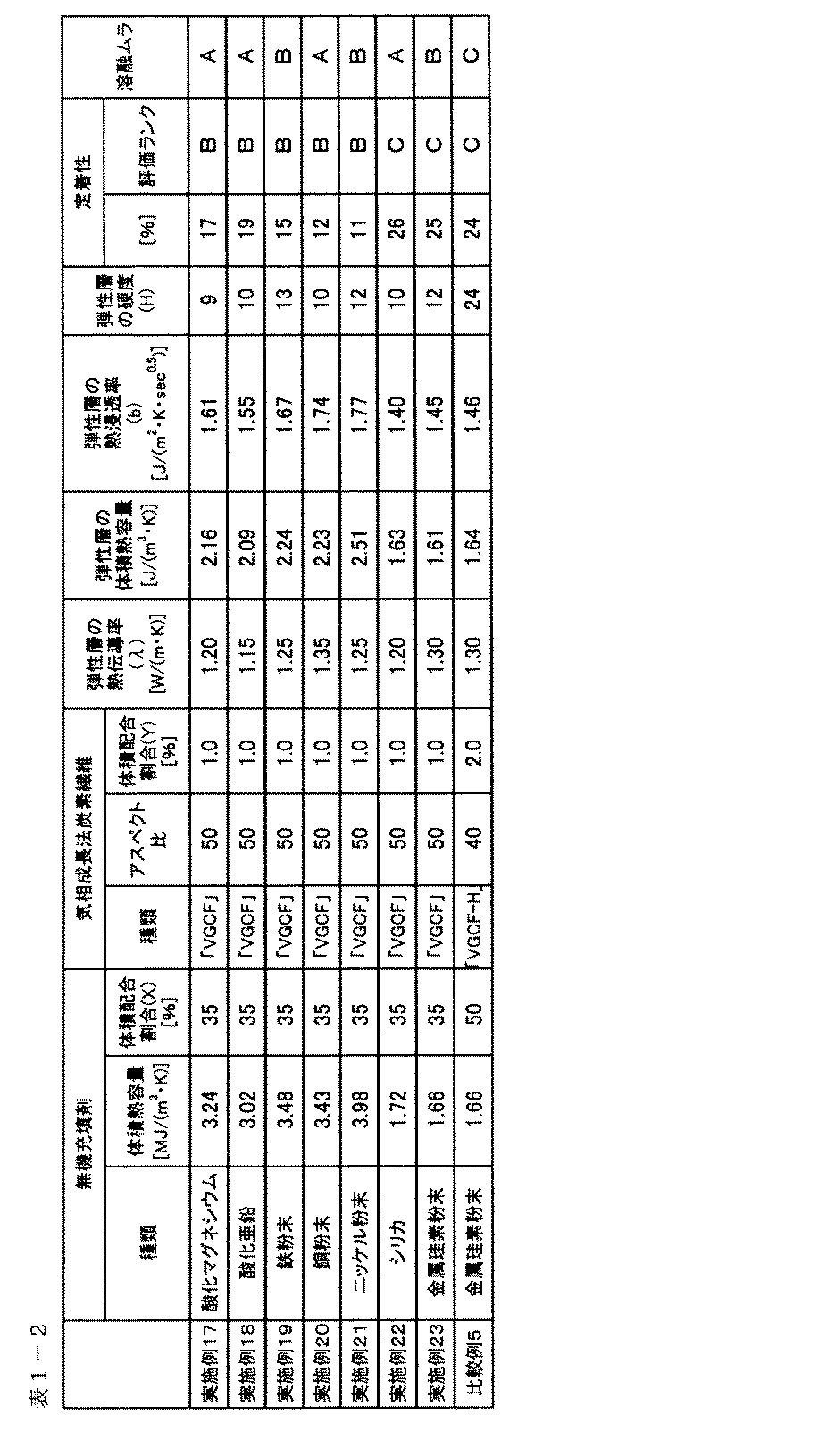
この出願は2012年12月26日に出願された日本国特許出願第2012-282976及び2013年12月5日に出願された日本国特許出願第2013-251804からの優先権を主張するものであり、その内容を引用してこの出願の一部とするものである。
Claims (12)
- 基材、弾性層および離型層を有する電子写真用の定着部材であって、
該弾性層が、シリコーンゴム、無機充填剤、および気相成長法炭素繊維を含有し、
該弾性層中の該無機充填剤の体積配合割合をX(%)、該気相成長法炭素繊維の体積配合割合をY(%)としたとき、下記式(1)、式(2)および式(3)を満たし、且つ、
該気相成長法炭素繊維は、繊維長と繊維径の比であるアスペクト比が、50以上であることを特徴とする定着部材:
3X+30Y≦170 ・・・(1)
25≦X≦50 ・・・(2)
0.5≦Y≦3.1 ・・・(3)。 - 前記気相成長法炭素繊維のアスペクト比が50以上、100以下である請求項1に記載の定着部材。
- 前記気相成長法炭素繊維の平均繊維径が、80~200nmである請求項1または2に記載の定着部材。
- 前記気相成長法炭素繊維の平均繊維長が、5~15μmである請求項1~3のいずれか一項に記載の定着部材。
- 前記無機充填剤の体積熱容量が3.0[MJ/m3・K]以上である請求項1~4のいずれか一項に記載の定着部材。
- 前記無機充填剤が、アルミナ、酸化マグネシウム、酸化亜鉛、鉄、銅およびニッケルから選ばれる少なくとも1つである請求項1~5のいずれか一項に記載の定着部材。
- 前記無機充填剤の平均粒径が、1~50μmである請求項1~6のいずれか一項に記載の定着部材。
- 前記無機充填剤の投影像における最小長さに対する最大長さの比の平均値が、1~2である請求項1~7のいずれか一項に記載の定着部材。
- エンドレスベルト形状を有し、かつ、前記弾性層の厚さが、100μm以上500μm以下である請求項1~8のいずれか一項に記載の定着部材。
- ローラ形状を有し、かつ、前記弾性層の厚さが、300μm以上10mm以下である請求項1~8のいずれか一項に記載の定着部材。
- 請求項1~10のいずれか一項に記載の定着部材と、該定着部材の加熱手段とを具備していることを特徴とする定着装置。
- 請求項11に記載の定着装置を具備していることを特徴とする電子写真画像形成装置。
Priority Applications (1)
| Application Number | Priority Date | Filing Date | Title |
|---|---|---|---|
| US14/280,891 US9134663B2 (en) | 2012-12-26 | 2014-05-19 | Electrophotographic fixing member, fixing apparatus and electrophotographic image forming apparatus |
Applications Claiming Priority (4)
| Application Number | Priority Date | Filing Date | Title |
|---|---|---|---|
| JP2012-282976 | 2012-12-26 | ||
| JP2012282976 | 2012-12-26 | ||
| JP2013-251804 | 2013-12-05 | ||
| JP2013251804A JP2014142611A (ja) | 2012-12-26 | 2013-12-05 | 電子写真用定着部材、定着装置及び電子写真画像形成装置 |
Related Child Applications (1)
| Application Number | Title | Priority Date | Filing Date |
|---|---|---|---|
| US14/280,891 Continuation US9134663B2 (en) | 2012-12-26 | 2014-05-19 | Electrophotographic fixing member, fixing apparatus and electrophotographic image forming apparatus |
Publications (1)
| Publication Number | Publication Date |
|---|---|
| WO2014103252A1 true WO2014103252A1 (ja) | 2014-07-03 |
Family
ID=51020373
Family Applications (1)
| Application Number | Title | Priority Date | Filing Date |
|---|---|---|---|
| PCT/JP2013/007440 Ceased WO2014103252A1 (ja) | 2012-12-26 | 2013-12-18 | 電子写真用定着部材、定着装置及び電子写真画像形成装置 |
Country Status (3)
| Country | Link |
|---|---|
| US (1) | US9134663B2 (ja) |
| JP (1) | JP2014142611A (ja) |
| WO (1) | WO2014103252A1 (ja) |
Cited By (4)
| Publication number | Priority date | Publication date | Assignee | Title |
|---|---|---|---|---|
| US9063491B2 (en) | 2012-12-19 | 2015-06-23 | Canon Kabushiki Kaisha | Electrophotographic fixing member, fixing apparatus and electrophotographic image forming apparatus |
| US9086664B2 (en) | 2012-12-26 | 2015-07-21 | Canon Kabushiki Kaisha | Fixing device with a heat generating layer containing a high molecular compound and a carbon fiber, and an electrophotographic image forming apparatus containing the fixing device |
| US9152110B2 (en) | 2013-01-18 | 2015-10-06 | Canon Kabushiki Kiasha | Pressure rotating member, method for manufacturing the same, and heating device |
| US9268273B2 (en) | 2013-09-10 | 2016-02-23 | Canon Kabushiki Kaisha | Pressure applying rotatable member, having a porous elastic layer with greater thermal conductivities in the axial and circumferential directions than in the thickness direction, and image heating apparatus having the same |
Families Citing this family (27)
| Publication number | Priority date | Publication date | Assignee | Title |
|---|---|---|---|---|
| US9395666B2 (en) | 2014-01-27 | 2016-07-19 | Canon Kabushiki Kaisha | Member for electrophotography and heat fixing device |
| JP6525733B2 (ja) | 2014-06-04 | 2019-06-05 | キヤノン株式会社 | 定着部材とその製造方法、定着装置および電子写真画像形成装置 |
| JP2016024217A (ja) | 2014-07-16 | 2016-02-08 | キヤノン株式会社 | 画像加熱装置 |
| JP6312544B2 (ja) * | 2014-07-16 | 2018-04-18 | キヤノン株式会社 | ニップ部形成部材、画像加熱装置、及びニップ部形成部材の製造方法 |
| JP6570339B2 (ja) | 2014-07-16 | 2019-09-04 | キヤノン株式会社 | 定着用部材及び加圧ローラ |
| JP2016064579A (ja) * | 2014-09-25 | 2016-04-28 | 三菱エンジニアリングプラスチックス株式会社 | 射出成形品の製造方法 |
| JP6472269B2 (ja) * | 2015-02-23 | 2019-02-20 | キヤノン株式会社 | 電子写真用部材 |
| JP6440531B2 (ja) * | 2015-03-05 | 2018-12-19 | キヤノン株式会社 | 電子写真用部材、及び、その製造方法 |
| JP2016184085A (ja) * | 2015-03-26 | 2016-10-20 | 富士ゼロックス株式会社 | 定着用加圧部材、定着装置、及び画像形成装置 |
| US9791812B2 (en) | 2015-09-29 | 2017-10-17 | Canon Kabushiki Kaisha | Rotatable feeding member and rotatable fixing member |
| JP6724462B2 (ja) * | 2016-03-24 | 2020-07-15 | 富士ゼロックス株式会社 | 円筒体、定着装置および画像形成装置 |
| US9891565B1 (en) | 2016-07-28 | 2018-02-13 | Canon Kabushiki Kaisha | Fixing member, fixing apparatus and electrophotographic image forming apparatus |
| US10228644B2 (en) | 2017-01-30 | 2019-03-12 | Canon Kabushiki Kaisha | Addition-curable liquid silicone rubber mixture, electrophotographic member, method for producing the same, and fixing apparatus |
| JP7073110B2 (ja) | 2017-01-30 | 2022-05-23 | キヤノン株式会社 | 付加硬化型液状シリコーンゴム混合物、電子写真用部材とその製造方法、並びに定着装置 |
| JP2018146676A (ja) * | 2017-03-02 | 2018-09-20 | コニカミノルタ株式会社 | 画像形成方法 |
| KR102236963B1 (ko) | 2017-03-28 | 2021-04-07 | 캐논 가부시끼가이샤 | 전자사진용 회전가능 가압체 및 그 제조 방법, 및 정착 장치 |
| JP7098388B2 (ja) | 2017-04-28 | 2022-07-11 | キヤノン株式会社 | 液状シリコーンゴム混合物、及び電子写真用部材の製造方法 |
| US10545439B2 (en) | 2018-06-07 | 2020-01-28 | Canon Kabushiki Kaisha | Fixed member and heat fixing apparatus |
| JP7114351B2 (ja) | 2018-06-07 | 2022-08-08 | キヤノン株式会社 | 定着部材および熱定着装置 |
| JP7321771B2 (ja) | 2018-06-07 | 2023-08-07 | キヤノン株式会社 | 定着部材及び熱定着装置 |
| JP7587357B2 (ja) * | 2019-05-23 | 2024-11-20 | キヤノン株式会社 | 定着部材、定着装置及び画像形成装置 |
| EP4007686B2 (de) * | 2019-08-01 | 2026-03-04 | Berndorf Aktiengesellschaft | Verfahren zur herstellung eines endlosbandes |
| US11467520B2 (en) | 2020-09-08 | 2022-10-11 | Canon Kabushiki Kaisha | Electrophotographic fixing member, fixing device, and electrophotographic image forming apparatus |
| US11747311B2 (en) | 2021-03-22 | 2023-09-05 | Honeywell International Inc. | Hydrocarbon byproduct monitoring of fibrous substrates |
| US11746007B2 (en) | 2021-03-22 | 2023-09-05 | Honeywell International Inc. | Fibrous substrates for hydrogen generation |
| JP7613270B2 (ja) * | 2021-05-26 | 2025-01-15 | 富士フイルムビジネスイノベーション株式会社 | 定着ベルト、定着装置、及び画像形成装置 |
| JP2022185860A (ja) * | 2021-06-03 | 2022-12-15 | 富士フイルムビジネスイノベーション株式会社 | ベルト、定着ベルト、定着装置、及び画像形成装置 |
Citations (4)
| Publication number | Priority date | Publication date | Assignee | Title |
|---|---|---|---|---|
| JP2004012649A (ja) * | 2002-06-05 | 2004-01-15 | Arai Pump Mfg Co Ltd | ローラ |
| JP2009263405A (ja) * | 2008-04-22 | 2009-11-12 | Shin Etsu Chem Co Ltd | 高熱伝導性シリコーンゴム組成物並びに熱定着ロール及び定着ベルト |
| JP2011186127A (ja) * | 2010-03-08 | 2011-09-22 | Sumitomo Electric Ind Ltd | 定着用ベルト |
| JP2012225986A (ja) * | 2011-04-15 | 2012-11-15 | Sumitomo Electric Ind Ltd | 定着用ベルト |
Family Cites Families (16)
| Publication number | Priority date | Publication date | Assignee | Title |
|---|---|---|---|---|
| JP2001062380A (ja) | 1999-08-31 | 2001-03-13 | Canon Inc | 円筒体表面への高粘度塗布液塗布方法、その方法により作製された定着ローラおよびその定着ローラの製造方法 |
| JP2002213432A (ja) | 2001-01-22 | 2002-07-31 | Sumitomo Electric Fine Polymer Inc | 被覆ローラまたはベルト及びその製造方法 |
| JP2004045851A (ja) | 2002-07-12 | 2004-02-12 | Konica Minolta Holdings Inc | 画像形成装置 |
| KR100779124B1 (ko) * | 2003-09-16 | 2007-11-28 | 쇼와 덴코 가부시키가이샤 | 기상성장 탄소섬유와 무기 미립자의 복합물 및 그 용도 |
| US8005413B2 (en) | 2007-06-26 | 2011-08-23 | Canon Kabushiki Kaisha | Image heating apparatus and pressure roller used for image heating apparatus |
| JP2009109952A (ja) * | 2007-11-01 | 2009-05-21 | Canon Inc | 加圧部材、及びその加圧部材を有する像加熱装置 |
| JP5926473B2 (ja) | 2008-09-10 | 2016-05-25 | 住友電気工業株式会社 | 定着用ベルト |
| JP5393134B2 (ja) | 2008-12-24 | 2014-01-22 | キヤノン株式会社 | 像加熱装置、像加熱装置に用いられる加圧ローラ及び加圧ローラの製造方法 |
| JP5414450B2 (ja) | 2009-10-19 | 2014-02-12 | キヤノン株式会社 | 加圧部材、像加熱装置、及び画像形成装置 |
| KR101813637B1 (ko) * | 2011-05-19 | 2018-01-02 | 에스프린팅솔루션 주식회사 | 발열 복합체를 포함하는 가열장치와 정착장치 |
| JP5863488B2 (ja) | 2012-02-03 | 2016-02-16 | キヤノン株式会社 | 無端ベルト及び像加熱装置 |
| JP6202918B2 (ja) | 2012-07-27 | 2017-09-27 | キヤノン株式会社 | 電子写真用部材、電子写真用部材の製造方法、定着装置および電子写真画像形成装置 |
| JP6061606B2 (ja) | 2012-10-16 | 2017-01-18 | キヤノン株式会社 | 加熱ベルト及び加熱装置 |
| EP2937737B1 (en) | 2012-12-19 | 2020-05-06 | Canon Kabushiki Kaisha | Electrophotographic fixing member, fixing apparatus and electrophotographic image forming apparatus |
| WO2014103263A1 (ja) | 2012-12-26 | 2014-07-03 | キヤノン株式会社 | 定着装置および電子写真画像形成装置 |
| JP6302253B2 (ja) | 2013-01-18 | 2018-03-28 | キヤノン株式会社 | 加圧用回転体及びその製造方法、並びに加熱装置 |
-
2013
- 2013-12-05 JP JP2013251804A patent/JP2014142611A/ja active Pending
- 2013-12-18 WO PCT/JP2013/007440 patent/WO2014103252A1/ja not_active Ceased
-
2014
- 2014-05-19 US US14/280,891 patent/US9134663B2/en active Active
Patent Citations (4)
| Publication number | Priority date | Publication date | Assignee | Title |
|---|---|---|---|---|
| JP2004012649A (ja) * | 2002-06-05 | 2004-01-15 | Arai Pump Mfg Co Ltd | ローラ |
| JP2009263405A (ja) * | 2008-04-22 | 2009-11-12 | Shin Etsu Chem Co Ltd | 高熱伝導性シリコーンゴム組成物並びに熱定着ロール及び定着ベルト |
| JP2011186127A (ja) * | 2010-03-08 | 2011-09-22 | Sumitomo Electric Ind Ltd | 定着用ベルト |
| JP2012225986A (ja) * | 2011-04-15 | 2012-11-15 | Sumitomo Electric Ind Ltd | 定着用ベルト |
Cited By (5)
| Publication number | Priority date | Publication date | Assignee | Title |
|---|---|---|---|---|
| US9063491B2 (en) | 2012-12-19 | 2015-06-23 | Canon Kabushiki Kaisha | Electrophotographic fixing member, fixing apparatus and electrophotographic image forming apparatus |
| US9086664B2 (en) | 2012-12-26 | 2015-07-21 | Canon Kabushiki Kaisha | Fixing device with a heat generating layer containing a high molecular compound and a carbon fiber, and an electrophotographic image forming apparatus containing the fixing device |
| US9152110B2 (en) | 2013-01-18 | 2015-10-06 | Canon Kabushiki Kiasha | Pressure rotating member, method for manufacturing the same, and heating device |
| US9304461B2 (en) | 2013-01-18 | 2016-04-05 | Canon Kabushiki Kaisha | Method for manufacturing pressure rotating member |
| US9268273B2 (en) | 2013-09-10 | 2016-02-23 | Canon Kabushiki Kaisha | Pressure applying rotatable member, having a porous elastic layer with greater thermal conductivities in the axial and circumferential directions than in the thickness direction, and image heating apparatus having the same |
Also Published As
| Publication number | Publication date |
|---|---|
| US20140255067A1 (en) | 2014-09-11 |
| US9134663B2 (en) | 2015-09-15 |
| JP2014142611A (ja) | 2014-08-07 |
Similar Documents
| Publication | Publication Date | Title |
|---|---|---|
| WO2014103252A1 (ja) | 電子写真用定着部材、定着装置及び電子写真画像形成装置 | |
| JP5553931B1 (ja) | 電子写真用定着部材、定着装置及び電子写真画像形成装置 | |
| JP4490474B2 (ja) | 電子写真用定着部材、定着装置および電子写真画像形成装置 | |
| JP5553932B1 (ja) | 定着装置および電子写真画像形成装置 | |
| CN106062642B (zh) | 定影构件、定影装置及图像形成设备 | |
| JP6429533B2 (ja) | 電子写真用定着部材、定着装置、および電子写真画像形成装置 | |
| JP6366662B2 (ja) | 定着部材、定着装置、画像形成装置および定着部材の製造方法 | |
| JP7073110B2 (ja) | 付加硬化型液状シリコーンゴム混合物、電子写真用部材とその製造方法、並びに定着装置 | |
| JP4597245B2 (ja) | 電子写真用定着部材、定着装置および電子写真画像形成装置 | |
| JP2019028184A (ja) | 定着部材、定着部材の製造方法、 | |
| JP6976838B2 (ja) | 付加硬化型液状シリコーンゴム混合物、電子写真用部材とその製造方法、並びに定着装置 | |
| JP4793065B2 (ja) | 表面処理器、画像形成装置、および画像形成方法 | |
| JP2025004836A (ja) | 電子写真部材、定着装置及び電子写真画像形成装置 | |
| JP2025120701A (ja) | 定着ベルト、定着装置及び電子写真画像形成装置 | |
| JP2006018173A (ja) | 定着用部材及び定着装置 | |
| JP2025119891A (ja) | 電子写真部材、定着装置及び電子写真画像形成装置 |
Legal Events
| Date | Code | Title | Description |
|---|---|---|---|
| 121 | Ep: the epo has been informed by wipo that ep was designated in this application |
Ref document number: 13868053 Country of ref document: EP Kind code of ref document: A1 |
|
| NENP | Non-entry into the national phase |
Ref country code: DE |
|
| 122 | Ep: pct application non-entry in european phase |
Ref document number: 13868053 Country of ref document: EP Kind code of ref document: A1 |