WO2014098027A1 - エアバッグ装置 - Google Patents
エアバッグ装置 Download PDFInfo
- Publication number
- WO2014098027A1 WO2014098027A1 PCT/JP2013/083606 JP2013083606W WO2014098027A1 WO 2014098027 A1 WO2014098027 A1 WO 2014098027A1 JP 2013083606 W JP2013083606 W JP 2013083606W WO 2014098027 A1 WO2014098027 A1 WO 2014098027A1
- Authority
- WO
- WIPO (PCT)
- Prior art keywords
- partition wall
- vent
- chamber
- overlap
- occupant
- Prior art date
- Legal status (The legal status is an assumption and is not a legal conclusion. Google has not performed a legal analysis and makes no representation as to the accuracy of the status listed.)
- Ceased
Links
Images





Classifications
-
- B—PERFORMING OPERATIONS; TRANSPORTING
- B60—VEHICLES IN GENERAL
- B60R—VEHICLES, VEHICLE FITTINGS, OR VEHICLE PARTS, NOT OTHERWISE PROVIDED FOR
- B60R21/00—Arrangements or fittings on vehicles for protecting or preventing injuries to occupants or pedestrians in case of accidents or other traffic risks
- B60R21/02—Occupant safety arrangements or fittings, e.g. crash pads
- B60R21/16—Inflatable occupant restraints or confinements designed to inflate upon impact or impending impact, e.g. air bags
- B60R21/23—Inflatable members
- B60R21/239—Inflatable members characterised by their venting means
-
- B—PERFORMING OPERATIONS; TRANSPORTING
- B60—VEHICLES IN GENERAL
- B60R—VEHICLES, VEHICLE FITTINGS, OR VEHICLE PARTS, NOT OTHERWISE PROVIDED FOR
- B60R21/00—Arrangements or fittings on vehicles for protecting or preventing injuries to occupants or pedestrians in case of accidents or other traffic risks
- B60R21/02—Occupant safety arrangements or fittings, e.g. crash pads
- B60R21/16—Inflatable occupant restraints or confinements designed to inflate upon impact or impending impact, e.g. air bags
- B60R21/23—Inflatable members
- B60R21/231—Inflatable members characterised by their shape, construction or spatial configuration
-
- B—PERFORMING OPERATIONS; TRANSPORTING
- B60—VEHICLES IN GENERAL
- B60R—VEHICLES, VEHICLE FITTINGS, OR VEHICLE PARTS, NOT OTHERWISE PROVIDED FOR
- B60R21/00—Arrangements or fittings on vehicles for protecting or preventing injuries to occupants or pedestrians in case of accidents or other traffic risks
- B60R21/02—Occupant safety arrangements or fittings, e.g. crash pads
- B60R21/16—Inflatable occupant restraints or confinements designed to inflate upon impact or impending impact, e.g. air bags
- B60R21/23—Inflatable members
- B60R21/231—Inflatable members characterised by their shape, construction or spatial configuration
- B60R21/233—Inflatable members characterised by their shape, construction or spatial configuration comprising a plurality of individual compartments; comprising two or more bag-like members, one within the other
-
- B—PERFORMING OPERATIONS; TRANSPORTING
- B60—VEHICLES IN GENERAL
- B60R—VEHICLES, VEHICLE FITTINGS, OR VEHICLE PARTS, NOT OTHERWISE PROVIDED FOR
- B60R21/00—Arrangements or fittings on vehicles for protecting or preventing injuries to occupants or pedestrians in case of accidents or other traffic risks
- B60R21/02—Occupant safety arrangements or fittings, e.g. crash pads
- B60R21/16—Inflatable occupant restraints or confinements designed to inflate upon impact or impending impact, e.g. air bags
- B60R21/23—Inflatable members
- B60R21/231—Inflatable members characterised by their shape, construction or spatial configuration
- B60R21/23138—Inflatable members characterised by their shape, construction or spatial configuration specially adapted for side protection
- B60R2021/23146—Inflatable members characterised by their shape, construction or spatial configuration specially adapted for side protection seat mounted
-
- B—PERFORMING OPERATIONS; TRANSPORTING
- B60—VEHICLES IN GENERAL
- B60R—VEHICLES, VEHICLE FITTINGS, OR VEHICLE PARTS, NOT OTHERWISE PROVIDED FOR
- B60R21/00—Arrangements or fittings on vehicles for protecting or preventing injuries to occupants or pedestrians in case of accidents or other traffic risks
- B60R21/02—Occupant safety arrangements or fittings, e.g. crash pads
- B60R21/16—Inflatable occupant restraints or confinements designed to inflate upon impact or impending impact, e.g. air bags
- B60R21/23—Inflatable members
- B60R21/231—Inflatable members characterised by their shape, construction or spatial configuration
- B60R21/233—Inflatable members characterised by their shape, construction or spatial configuration comprising a plurality of individual compartments; comprising two or more bag-like members, one within the other
- B60R2021/23324—Inner walls crating separate compartments, e.g. communicating with vents
-
- B—PERFORMING OPERATIONS; TRANSPORTING
- B60—VEHICLES IN GENERAL
- B60R—VEHICLES, VEHICLE FITTINGS, OR VEHICLE PARTS, NOT OTHERWISE PROVIDED FOR
- B60R21/00—Arrangements or fittings on vehicles for protecting or preventing injuries to occupants or pedestrians in case of accidents or other traffic risks
- B60R21/02—Occupant safety arrangements or fittings, e.g. crash pads
- B60R21/16—Inflatable occupant restraints or confinements designed to inflate upon impact or impending impact, e.g. air bags
- B60R21/23—Inflatable members
- B60R21/231—Inflatable members characterised by their shape, construction or spatial configuration
- B60R21/2334—Expansion control features
- B60R21/2346—Soft diffusers
Definitions
- the present invention relates to an airbag device that inflates and deploys between an occupant and a side wall portion in a vehicle compartment to restrain the occupant when an impact occurs on the vehicle.
- An airbag is a safety device that operates in an emergency such as a vehicle collision, and inflates and deploys with gas pressure to receive and protect an occupant.
- An airbag is a safety device that operates in an emergency such as a vehicle collision, and inflates and deploys with gas pressure to receive and protect an occupant.
- airbags There are various types of airbags depending on the installation location and application.
- a front airbag is provided in the center of the steering wheel in order to protect the driver from collisions in the front-rear direction.
- curtain airbags that inflate and deploy along the side windows from the ceiling of the wall and from the side of the seat to the side of the passenger Side airbags that are inflated and deployed are provided.
- the air bag is equipped with a gas generator called an inflator as a gas supply source.
- a gas generator called an inflator as a gas supply source.
- inflators There are various types of inflators depending on the type of air bag and its installation location. For example, disc type (disc type) inflators are mainly used for front airbags and the like, and cylinder type (tubular) inflators are mainly used for curtain airbags and side airbags. .
- Patent Document 1 describes a side airbag and a cylinder-type inflator.
- the side airbag is partitioned into two upper and lower rooms (a room in the airbag is also called a “chamber”) by a partition wall.
- This partition is provided with an insertion part as a hole connecting the two rooms, and the inflator is arranged in this insertion part.
- Patent Document 1 it is supposed that each part of an occupant can be protected with an appropriate pressure by dividing into two rooms.
- the present invention has been made in view of such a problem, and an object of the present invention is to provide an airbag device that can speed up inflation and deployment and improve occupant restraint performance.
- a typical configuration of an airbag device is a bag-like cushion portion that receives gas and inflates and deploys, and the interior of the cushion portion is partitioned into a plurality of chambers. It is provided with the partition wall and the vent means which can be opened and closed provided in the partition wall, Comprising: The vent means which a passenger
- the airbag apparatus has the above-described configuration, for example, first, gas is preferentially supplied to the first chamber, and an occupant is quickly received in the first chamber.
- the partition wall bends together with the first chamber, and the vent means opens to inflate and deploy the second chamber, thereby achieving full occupant restraint with a wider protection area.
- the vent means opens to inflate and deploy the second chamber, thereby achieving full occupant restraint with a wider protection area.
- the vent means includes one or more vent holes provided on the partition wall through which gas can pass from the first chamber to the second chamber, and covers the vent hole on the first chamber side.
- a patch member that is joined in a state where at least a part of the patch member can be separated, and a connecting member that connects the patch member and a predetermined region in the first chamber facing the patch member, and the length of the connecting member is At least the distance between the vent hole and the predetermined region in the shape when the first chamber is sufficiently expanded and deployed may be used.
- the air bag device having the above configuration first supplies gas preferentially to the first chamber, and promptly receives the occupant in the first chamber.
- the partition wall bends together with the first chamber, and the distance from the vent hole to the predetermined region that is the root of the connecting member increases. That is, the patch member is pulled by the connecting member, and the patch member is separated from the partition wall. This opens the vent hole and increases the flow rate of the gas passing through the vent hole from the first chamber to the second chamber. Then, the second chamber is inflated and deployed, and the passenger is fully restrained with a wider protection area.
- the first chamber that is inflated and deployed first is realized as a rear chamber on the rear side of the vehicle, and the second chamber that is inflated and deployed next is a front chamber on the front side of the vehicle, the first impact of the passenger is received by the rear chamber. This is preferable because the front side of the occupant can be received more widely later by the front chamber.
- the length of the connecting member may be equal to the distance between the vent hole and the predetermined region in the shape when the first chamber is sufficiently expanded and deployed. According to this configuration, it is possible to suitably realize the second chamber that starts to expand when the occupant comes into contact with the first chamber.
- the partition wall has a long shape extending in the up-down direction or the vehicle front-rear direction inside the cushion portion, and the patch member has side edges joined to both sides of the vent hole in the partition wall, Alternatively, the front and rear edges of the vehicle may be opened from the partition wall.
- the partition portion bends so as to be pushed in the short direction.
- the gap is suitably opened according to the deflection of the partition wall, and gas can be passed to the vent hole.
- the fact that the upper and lower edges and the like are open means that the upper and lower edges and the like are not joined to the partition wall by stitching or the like.
- vent holes are provided on at least two places on the partition wall, the upper part and the lower part in the cushion part, and the vent holes provided on the upper part of the partition wall are provided in the vicinity of the region where the shoulder part of the passenger contacts.
- the vent hole provided in the lower part of the partition wall may be provided in the vicinity of the region where the occupant's waist contacts.
- the shoulders and lower back of the occupant's body are particularly susceptible to load.
- the vent means includes a slit vent provided as a straight cut line in the partition wall, and the slit vent opens when the partition wall is bent to flow a gas from the first chamber to the second chamber. May increase.
- the partition wall has a long shape extending in the up-down direction or the vehicle front-rear direction inside the cushion portion, and the slit vent is straight in at least one place on the partition wall in the short direction of the partition wall. It may be provided in a shape that extends. With this configuration, for example, when the occupant contacts the cushion portion from the vehicle width direction, the partition portion bends so as to be pushed in the short direction. At this time, if the slit vent is provided in the short direction on the partition wall, the slit vent can be suitably opened according to the deflection of the partition wall.
- the slit vents are provided on at least two locations on the partition wall, the upper part and the lower part in the cushion part, and the slit vents provided on the upper part of the partition wall are provided in the vicinity of a region where the shoulder part of the occupant contacts.
- the slit vent provided in the lower part of the partition wall may be provided in the vicinity of a region where the occupant's waist contacts.
- the shoulder and waist of the occupant's body are particularly susceptible to load.
- the partition wall includes a first member and a second member, which are cloth materials independent of each other, and the vent means is provided by overlapping the ends of the first member and the second member on the partition wall.
- a first overlap vent may be included that opens upon deflection.
- the partition wall has a shape extending in the up-down direction or the vehicle front-rear direction inside the cushion portion, and the first member and the second member are arranged side by side in the up-down direction or the vehicle front-rear direction.
- the wrap vent may be provided to extend laterally on the partition wall. According to the above configuration, for example, when the occupant contacts the cushion portion from the lateral direction (vehicle width direction), the partition portion also bends in the lateral direction (width direction). At this time, if the overlap vent is provided in the partition wall in the lateral direction, the overlap vent can be preferably opened by utilizing the deflection of the partition wall.
- the partition wall further includes a third member made of a cloth material spaced from the first member, and the vent means is further provided on the partition wall by overlapping ends of the second member and the third member.
- the partition wall may include a second overlap vent that opens by bending.
- the first overlap vent may be provided in the vicinity of an area where the occupant's shoulder contacts, and the second overlap vent may be provided in the vicinity of an area where the occupant's waist contacts.
- the shoulder and lower back of the occupant's body are particularly susceptible to load.
- the partition wall includes a first member and a second member, which are cloth materials independent of each other, and has an overlap portion where ends of the first member and the second member overlap each other, and the vent means includes the first member And a sewing line that joins the first member and the second member, provided in the overlap portion of the second member, and an intermediate portion of the sewing line is opened, and gas is supplied from the first chamber to the second chamber.
- One or more overlap vents that can pass into the chamber.
- Said 1st member and 2nd member are elongate shape, Comprising: The overlap part of 1st member and 2nd member is provided in the mutual long edge part, A sewing line is a mutual long edge. Gas may flow in the short direction of the first member and the second member passing through the overlap vent. With this configuration, a partition wall and an overlap vent for giving priority to the expansion and deployment of the first chamber can be suitably realized.
- the above sewing line may be bent or curved along the gas flow direction from the longitudinal direction at the overlap vent.
- the overlap vent may have a diameter on the first chamber side larger than a diameter on the second chamber side.
- the overlap vent may be provided such that gas flowing through the overlap vent flows from the vehicle inner side toward the vehicle outer side in the vehicle width direction.
- the above-mentioned second chamber may have a reinforcing cloth in a region where the gas flowing in from the overlap vent directly hits. Thereby, it becomes possible to improve the durability of the cushion portion.
- the above overlap vents are provided on the partition wall at at least two places, the upper part and the lower part in the cushion part, and the overlap vents on the upper part of the partition wall are provided in the vicinity of the region where the shoulder part of the occupant contacts.
- the overlap vent at the lower part of the partition wall may be provided in the vicinity of the area where the occupant's waist contacts.
- the shoulder and lower back of the occupant's body are particularly susceptible to load.
- the partition wall may be provided in an area where the occupant comes in contact with the cushion part and the surface of the cushion part is deformed in the event of an emergency of the vehicle. According to this structure, the partition wall which bends by a passenger
- the airbag device may be a side airbag that is inflated and deployed on the side of the seat.
- the partition wall may partition the cushion portion into a rear chamber on the rear side of the vehicle and a front chamber on the front side of the vehicle, and the vent means may supply gas from the rear chamber to the front chamber.
- the rear chamber on the vehicle rear side is likely to come into contact with a load-prone part such as the shoulder of an occupant. Therefore, in the above, first, the rear chamber is rapidly inflated and deployed, and then the second chamber is used as a front chamber to protect the occupant's arms and the like. Thereby, a passenger
- the airbag device is further a cylinder-type inflator installed in a predetermined chamber, a diffuser unit installed to surround the inflator in a cylindrical shape, and guides gas from the inflator in the vertical direction in the chamber, , May be provided.
- the inflator provided with the diffuser portion allows the chamber to be filled with gas more quickly.
- an airbag device that can speed up inflation and deployment and improve occupant restraint performance.
- E1 occupant's shoulder
- E2 occupant's waist
- E3 occupant's arm
- E4 occupant's abdomen
- L1 sewing line in the first embodiment
- P2 lower part 100 ... Airbag, 102 ... Seat, 104 ... Cushion part, 106 ... Seat back, 108 ... Rear chamber, 110 ... Front chamber, 112 ... Occupant, 114 ... Inflator, 116 ... Stud bolt, 118 ... vent hole, 120: partition wall
- 122 vent hole
- 122 a upper vent hole
- 122 b lower vent hole
- 124 impactor
- 126 diffuser section
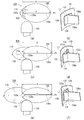
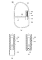
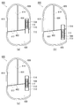
- FIG. 1 is a diagram illustrating an airbag device (hereinafter referred to as an airbag 100) according to a first embodiment of the present invention.
- the airbag 100 according to the present invention is realized as a so-called side airbag that inflates and deploys on the side of a vehicle right side seat (hereinafter, seat 102).
- the installation location of the airbag 100 which is a side airbag, is not limited to the seat 102, and may be another location as long as it can be inflated and deployed to the side of the occupant, such as a side door trim.
- the cushion part 104 is a bag-like part that catches the occupant in an emergency such as when an impact occurs on the vehicle, and inflates and deploys in a flat shape between the occupant and the side door.
- the cushion part 104 is formed by laminating a plurality of base fabrics constituting the surface and sewing or adhering them.
- the cushion part 104 is wound or folded and accommodated in a housing (not shown) provided on the side part of the seat back 106. Since the cushion portion 104 in the stored state is covered with a seat cover or the like, it cannot be visually recognized from the outside. During operation, the seat cover or the like is cleaved and inflated and deployed to the side of the occupant.
- the cushion portion 104 is partitioned into two chambers. As can be seen from FIG. 1A, the cushion portion 104 is provided with a rear chamber 108 on the rear side of the vehicle as a first chamber and a front chamber 110 on the front side of the vehicle as a second chamber.
- FIG. 1 (b) is a view of the cushion portion 104 of FIG. 1 (a) as viewed from the vehicle outer side in the vehicle width direction.
- FIG. 1B illustrates a dummy doll AM50 simulating a physique adapted to 50% of an adult male as the occupant 112 in order to represent the positional relationship between the cushion portion 104 and the occupant.
- the rear chamber 108 in the cushion portion 104, particularly protects a portion that is more susceptible to a load such as the shoulder E ⁇ b> 1 and the waist E ⁇ b> 2 of the occupant 112.
- the front chamber 110 is configured to protect the arm portion E3, the abdominal portion E4, and the like.
- FIG. 2 is a diagram illustrating the cushion portion 104 of FIG.
- the cushion part 104 of FIG.1 (b) is illustrated seeing from the vehicle inner side (occupant 112 side) of a vehicle width direction.
- an inflator 114 which is a gas generator, is provided inside the rear chamber 108.
- the cushion portion 104 is inflated by the pressure of the gas supplied from the inflator 114 to restrain the occupant.
- the inflator 114 employed in this embodiment is a cylinder type (tubular type).
- the inflator 114 includes a stud bolt 116.
- the stud bolt 116 is exposed from the rear chamber 108 and is fastened to a housing or the like on the side portion of the seat 102 (see FIG. 1A).
- the currently popular inflator 114 is a type in which a gas generating agent is filled and burned to generate gas, a type in which compressed gas is filled and gas is supplied without generating heat, or There is a hybrid type using both combustion gas and compressed gas. Any type of inflator 114 can be used.
- the gas supplied from the inflator 114 is exhausted from an exhaust hole 118 provided on the front side (left side in the drawing) of the cushion portion 104 after the cushion portion 104 is inflated and deployed.
- FIG. 2B is a diagram illustrating the process of inflating and deploying the cushion portion 104 of FIG.
- the cushion portion 104 of the airbag 100 is configured such that the rear chamber 108 is first inflated and deployed preferentially.
- the front chamber 110 is inflated as shown in the right diagram of FIG. 2B, triggered by the contact of the occupant 112 (see FIG. 1B) with the rear chamber 108 inflated and deployed. expand.
- deployment is further demonstrated.
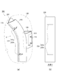
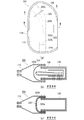
- FIG. 3 is a diagram illustrating the internal configuration of the cushion portion 104 of FIG.
- FIG. 3A illustrates the internal configuration through the base fabric outside the cushion portion 104 of FIG.
- the rear chamber 108 and the front chamber 110 are partitioned by a partition wall 120.
- the partition wall 120 Even if the partition wall 120 has a long shape extending in the vertical direction inside the cushion portion 104, the partition wall 120 is made of a cloth material.
- the partition wall 120 also plays a role of preferentially expanding and deploying the rear chamber 108.
- the partition wall 120 is provided with a vent means that can be opened and closed.
- a vent hole 122 is provided in the partition wall 120, and gas is supplied from the rear chamber 108 side to the front chamber 110 side through the vent hole 122. Since the vent holes 122 are provided in two places, that is, the upper vent hole 122a and the lower vent hole 122b of the partition wall 120, it is possible to efficiently supply gas to the front chamber 110 and quickly fill it. It has become. However, the vent hole 122 is still closed when the rear chamber 108 is expanded and deployed. The vent hole 122 opens when the partition wall 120 is bent by an external force when the occupant comes into contact with the rear chamber 108. Thus, the cushion part 104 has a mechanism in which the expansion and deployment of the rear chamber 108 is prioritized.
- FIG. 3B is a schematic view of the state of the partition wall 120 of FIG. 3A before expansion and deployment of the front chamber 110 as viewed from the direction of arrow A in FIG. 3A.
- the vent hole 122 is a circular hole provided near the center of the partition wall 120 in the width direction.
- FIG. 3C illustrates the rear chamber 108 side, which is the back side of the partition wall 120 in FIG. As illustrated in FIG. 3C, the vent hole 122 (FIG. 3B) is covered with a patch member 128 on the rear chamber 108 side.
- the patch member 128 has side edges 130 joined to both sides of the vent hole 122a in the partition wall 120 by a sewing line L1, and the upper edge 132 and the lower edge 134 are partitioned. It is in an open state without being joined to the wall 120.
- a strip-shaped connecting member 136 is connected to the patch member 128 in the rear chamber 108.
- Each of the connecting members 136 connects the patch member 128 and predetermined regions P1 and P2 on the vehicle rear side facing the patch member in the peripheral portion of the rear chamber 108.
- the connecting member 136 pulls the patch member 128 to open the vent hole 122 when the occupant comes into contact with the cushion portion 104 and the partition wall 120 bends together with the cushion portion 104 when the cushion portion 104 is inflated and deployed. have.
- the vent hole 122 is closed by the patch member 128 in a state where the partition wall 120 before the occupant is in contact is not bent, and the gas flow rate at the time when the gas pressure is simply applied from the rear chamber 108 side, Compared to the total amount of gas supplied from the inflator 114, the amount is small.
- FIG. 4 is a development view of the base fabric constituting the cushion portion 104 of 3 (a).
- the partition wall 120 has a lower portion extending from the center to the interior of the cushion portion 104 in a substantially vertical direction, but an upper portion is inclined to the front chamber 110 side.
- FIG. 4B is a cross-sectional view taken along line BB in FIG. As illustrated in FIG. 4B, the partition wall 120 is configured by further sewing two base fabrics in a region on the front chamber 110 side of the base fabric configuring the front chamber 110.
- FIG. 4C C—C sectional view of FIG. 4A
- the partition wall 120 is provided with a vent hole 122a, and a patch is provided on the rear chamber 108 side of the vent hole 120a.
- a member 128a is provided.
- the patch member 128a is composed of two base fabrics integrated with the connecting member 136a.
- the connecting member 136a is sewn to a region P1 in which the vehicle rear side is the rear end of the rear chamber 108 on
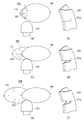
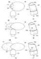
- FIG. 5 is a schematic view illustrating a process in which the cushion portion 104 of FIG. FIG. 5A illustrates the cushion portion 104 at the beginning of the inflating and deploying illustrated corresponding to FIG.
- the impactor 124 illustrated in FIG. 5A is a test device used in a vehicle airbag release prevention performance evaluation test or the like for a curtain airbag. In the following description, the impactor 124 is treated as a model of an occupant.
- the rear chamber 108 is first inflated and deployed first. At this time, only the gas pressure is applied to the partition wall 120, and the patch member 128a covering the vent hole (typically, the vent hole 122a) is not opened as illustrated in FIG. 5B. . Actually, even in this state, the gas leaks between the vent hole 122a and the patch member 128a. However, since the leaked amount is small compared to the total amount of gas supplied from the inflator 114, the vent hole 122a can be regarded as closed in practice.
- the length of the connecting member 136 (representatively, the connecting member 136a in FIG. 5) is referred to as a length Y.
- the rear chamber 108 when inflated and deployed almost fully has a predetermined shape that is the root of the connection hole 136 and the vent hole 122 (typically, the vent hole 122a in FIG. 5) in the shape before the passenger contacts.
- a linear distance connecting the region (region P1 in FIG. 5) is defined as a distance X.
- the length Y of the connecting member 136a is set to at least the distance X between the vent hole 122a and the region P1 in the shape before the occupant contacts when the cushion portion 104 is inflated and deployed.
- the length Y of the connecting member 136a is set to be approximately equal to the distance X.
- the rear chamber 108 becomes thin in the vehicle width direction and deforms so as to extend in the vehicle front-rear direction. Accordingly, the partition wall 120 is also bent so as to be pushed in the vehicle width direction, and the vent hole 122a moves to the vehicle front side, and the distance X is extended.
- the connecting member 136a is set to the length Y described above (a length substantially equal to the distance X)
- the patch member 128a is relatively pulled by the connecting member 136a when viewed from the vent hole 122a. It will be.
- FIG. 5D the upper edge 132 and the lower edge 134 of the patch member 128a are separated from the partition wall 120, the gap is expanded, and the gas flows into the vent hole 122a.
- the length Y of the connecting member 136 is set to be approximately equal to the distance X (the length Y may be slightly longer than the distance X).
- the length Y of the connecting member 136 is equal to or less than the distance X, a force for pulling the patch member 128 is generated in the connecting member 136 at the same time as or after the completion of the expansion and deployment of the rear chamber 108. . According to this, the gas supply to the front chamber 110 immediately after the occupant comes into contact is performed more smoothly.
- the length Y of the connecting member 136 is substantially equal to or slightly longer than the distance X as in the present embodiment, the supply of gas to the front chamber 110 is prevented from contacting the occupant rear chamber 108.
- the internal pressure of the rear chamber 108 can be released at an appropriate timing while reliably protecting the occupant during a first impact with a large impact (the first contact of the occupant with the rear chamber 108). Therefore, more preferable airbag characteristics can be obtained.
- the patch member 128a is joined to the partition wall 120 at the side edge 130 so that a gap is formed between the patch member 128a and the vent hole 122a when the partition wall 120 is pushed in the vehicle width direction by the contact of the occupant.
- the upper edge 132 and the lower edge 134 are not joined to the partition wall 120 and are open.
- the upper edge 132 and the lower edge 134 are opened. This is because the partition wall 120 extends in the vehicle vertical direction in this embodiment.
- the partition wall 120 extends in the vehicle front-rear direction. In this case, the front and rear edges of the patch member may be opened.
- the vent hole 122 is opened in the above-described process, the partition wall 120 is positioned so as to be more easily bent. It is preferable to be provided in the inside. Further, in the present embodiment, in order to make the vent hole 122 easy to open, the vent hole 122 is provided in the vicinity of a region that comes into contact with a portion of the body of the occupant 112 that is susceptible to a load. For example, the upper vent hole 122a is provided in the vicinity of the region where the shoulder E1 (FIG. 1B) of the occupant 112 contacts, and the lower vent hole 122b is provided in the vicinity of the region where the lumbar E2 of the occupant 112 contacts. ing.
- the cushion portion 104 of the airbag 100 first, gas is preferentially supplied to the rear chamber. Then, the rear chamber 108 quickly contacts and receives a load-applying portion such as the shoulder E1 or the waist E2 of the occupant 112 described with reference to FIG. Next, when the occupant 112 comes into contact with the rear chamber 108, the front chamber 110 expands and deploys and widely receives the arm portion E3, the abdominal portion E4, and the like of the occupant 112. As described above, in the airbag 100, first, a portion related to the first contact with the occupant (first impact) is quickly inflated and deployed, and then further inflated and deployed, thereby improving the occupant restraint performance. It is possible.
- a diffuser portion 126 is installed as a rectifying member around the inflator 114 so that the rear chamber 108 and the front chamber 110 are efficiently filled with gas.
- the diffuser portion 126 is installed inside the rear chamber 108 so as to surround the inflator 114 in a cylindrical shape, and guides the gas from the inflator 114 in the vertical direction in the rear chamber.
- the rear chamber 108 is efficiently filled with gas, and the gas can easily flow from the upper and lower vent holes 122 toward the front chamber 110.
- the patch member 128 and the connecting member 136 are integrally formed by sewing two pieces of cloth material.
- the patch member 128 and the connecting member 136 may be formed by one piece of cloth material, and may be configured to be connected after being provided independently of each other. It goes without saying.
- FIG. 6 is a diagram illustrating an airbag device (hereinafter, airbag 200) according to the second embodiment of the present invention.
- FIG. 6 illustrates the cushion portion 204 of the airbag 200 corresponding to the cushion portion 104 of FIG. 3 described above.
- the description is abbreviate
- the rear chamber 108 and the front chamber 110 are partitioned by a partition wall 220. Even if the partition wall 220 has a long shape extending in the vertical direction inside the cushion portion 204, the partition wall 220 is made of a cloth material. The partition wall 220 also plays a role of preferentially expanding and deploying the rear chamber 108.
- Venting means is also provided in the partition wall 220.
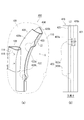
- a slit vent 222 is provided, and gas is supplied from the rear chamber 108 side to the front chamber 110 side through the slit vent 222. Since the slit vent 222 is provided at a total of two locations, that is, the upper slit vent 222a and the lower slit vent 222b of the partition wall 220, the gas can be efficiently supplied to the front chamber 110 and quickly filled. It has become. However, the slit vent 222 is still closed when the rear chamber 108 is inflated and deployed. The slit vent 222 is opened when the partition wall 220 is bent by an external force when the occupant contacts the rear chamber 108. Thus, the cushion part 204 has a mechanism in which the expansion and deployment of the rear chamber 108 is prioritized.
- FIG. 6B is a schematic diagram of the state before the expansion and deployment of the front chamber 110 of the partition wall 220 in FIG. 6A as viewed from the direction of arrow H in FIG.
- the slit vent 222 is provided as a linear cut line extending in the short direction of the partition wall 220.
- the slit vent 222 is closed when the partition wall 220 before the occupant comes into contact is not bent, and the gas flow rate is small when the gas pressure is simply applied from the rear chamber 108 side.
- FIG. 7 is a development view of the base fabric constituting the cushion portion 204 of FIG.
- the partition wall 220 has a lower portion extending from the central portion thereof in the cushion portion 204 substantially along the vertical direction, but an upper portion thereof is inclined to the front chamber 110 side.
- FIG. 7B is a cross-sectional view taken along the line II in FIG.
- the partition wall 220 is configured by further sewing two base fabrics in a region of the base fabric constituting the rear chamber 108 on the front chamber 110 side.
- FIG. 7C the JJ sectional view of FIG. 7A
- the slit vent 222 is provided with a notch in the base fabric, and the rear chamber 108 and the front chamber 110 are separated from each other. Communicates.
- FIG. 8 is a diagram illustrating a process in which the cushion portion 204 of FIG. 7 is inflated and deployed.
- FIG. 8A illustrates the cushion portion 204 at the beginning of the inflating and deploying illustrated corresponding to FIG. 7B.
- the rear chamber 108 first expands and deploys first.
- the slit vent typically, the slit vent 222a
- the gas leaks through the slit vent 222a.
- the slit vent 222a can be regarded as closed in practice.
- the rear chamber 108 becomes thin in the vehicle width direction and deforms so as to extend in the vehicle front-rear direction. Accordingly, the partition wall 120 is also bent in the vehicle width direction. This deflection opens the slit vent 222a as illustrated in FIG. As described above, the slit vent 222a opens in the vehicle width direction (the shorter side of the partition wall 220) with respect to the partition wall 220 extending in the vehicle vertical direction so that it opens when the partition wall 220 is pushed in the vehicle width direction by the contact of the occupant. Direction).
- the partition wall 220 is set at a position where the partition wall 220 is more easily bent, and the surface of the cushion portion 204 is deformed when the occupant comes into contact. It is preferable to provide it inside the region.
- the slit vent 222 in order to make the slit vent 222 easy to open, is provided in the vicinity of a region that comes into contact with a portion of the occupant's body that is susceptible to a load.
- the upper slit vent 222a is provided in the vicinity of the area where the occupant's shoulder E1 (FIG. 1B) contacts
- the lower slit vent 222b is provided in the vicinity of the area where the occupant's waist E2 contacts. .
- the cushion portion 204 of the airbag 200 first, gas is preferentially supplied to the rear chamber. Then, the rear chamber 108 quickly contacts and receives a load-applying portion such as the shoulder E1 or the waist E2 of the occupant 112 described with reference to FIG. Next, when the occupant 112 comes into contact with the rear chamber 108, the front chamber 110 expands and deploys and widely receives the arm portion E3, the abdominal portion E4, and the like of the occupant 112. As described above, in the airbag 200, first, a portion related to the first contact with the occupant (first impact) is quickly inflated and deployed, and then further inflated and deployed, thereby improving the occupant restraint performance. It is possible.
- the rear of the airbag 200 It can be expected that only the chamber 108 is deployed and the front chamber 110 is undeployed to avoid excessive contact with the passenger. Therefore, the slit vent 222 provided in the airbag 200 is also effective as a countermeasure against this OOP.
- a diffuser portion 126 is installed as a rectifying member around the inflator 114 so that the rear chamber 108 and the front chamber 110 are efficiently filled with gas.
- the diffuser portion 126 is installed inside the rear chamber 108 so as to surround the inflator 114 in a cylindrical shape, and guides the gas from the inflator 114 in the vertical direction in the rear chamber.
- the rear chamber 108 is efficiently filled with gas, and the gas can easily flow from the upper and lower slit vents 222 toward the front chamber 110.
- the two slit vents 222a and 222b are provided. However, if it is possible to satisfy the required performance, only one configuration may be provided, or three or more configurations may be provided. Good.
- the partition wall 220 may be installed so as to extend in the vehicle front-rear direction, for example, and in that case, a slit vent may be provided in front of the partition wall and in the rear of the vehicle.
- the partition wall 220 is produced by stitching cloth materials, it is needless to say that the partition wall 220 may be composed of one cloth material.
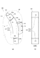
- FIG. 9 is a diagram illustrating an airbag device (hereinafter, airbag 300) according to the third embodiment of the present invention. 9 illustrates the cushion portion 304 of the airbag 300 corresponding to the cushion portion 104 of FIG. 3 described above.
- the description is abbreviate
- the rear chamber 108 and the front chamber 110 are partitioned by a partition wall 320.
- the partition wall 320 has a long shape extending in the vertical direction inside the cushion portion 304 and is made of a cloth material.
- the partition wall 320 also plays a role of preferentially expanding and deploying the rear chamber 108.
- the partition wall 320 is a cloth material and includes a first member 320a, a second member 320b, and a third member 320c that are independent of each other.
- the first member 320 a constitutes the upper part of the partition wall 320
- the third member 320 c constitutes the lower part of the partition wall 320.
- the first member 320a and the third member 320c are separated from each other, and the second member 320b is provided on the front chamber 110 side so as to extend between the first member 320a and the third member 320c.
- the first member 320a to the third member 320c are arranged in the vertical direction, and are sewn and joined along the edge in the width direction.
- the overlapping portions of the second member 320b, the first member 320a, and the third member 320c are opened without being connected, and an overlap vent 322 is formed as vent means.
- the overlap vent 322 is a gas passage, and gas is supplied from the rear chamber 108 side to the front chamber 110 side through the overlap vent 322.
- the overlap vents 322 are provided at a total of two locations of the first overlap vent 322a at the upper part of the partition wall 320 and the second overlap vent 322b at the lower part, the gas is efficiently supplied to the front chamber 110. And can be quickly filled. However, the overlap vent 322 is still closed when the rear chamber 108 is inflated and deployed. The overlap vent 322 is bent and opened together with the partition wall 320 being bent by an external force when the occupant comes into contact with the rear chamber 108. Thus, the cushion part 104 has a mechanism in which the expansion and deployment of the rear chamber 108 is prioritized.
- FIG. 9B is a schematic view of the state of the partition wall 320 of FIG. 9A before expansion and deployment of the front chamber 110 viewed from the arrow K direction of FIG. 9A.
- the upper end portion 321 and the lower end portion 323 of the second member 320b forming the overlap vent 322 are laterally (vehicle width direction) with respect to the partition wall 320 extending in the vertical direction (vertical direction) of the cushion portion 304. It is provided in an extending shape.
- the overlap vent 322 is closed when the partition wall 320 before the occupant comes into contact is not bent, and the gas flow rate is supplied from the inflator 114 when gas pressure is simply applied from the rear chamber 108 side. It is very small compared to the total amount of gas.
- FIG. 10 is a development view of the base fabric constituting the cushion portion 304 of FIG. 9A.
- the partition wall 320 has a lower portion extending from the center to the interior of the cushion portion 304 along the vertical direction, but an upper portion is inclined to the front chamber 110 side.
- FIG. 10B is a cross-sectional view taken along the line MM in FIG. As illustrated in FIG. 10B, the partition wall 320 is configured by sewing the second member 320b and the like in a region on the front chamber 110 side of the base fabric constituting the rear chamber. In the overlap vent 322, for example, the first member 320a and the second member 320b overlap without being connected, as illustrated in FIG. 10C (an NN cross-sectional view in FIG. 10A). Yes.
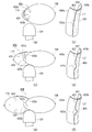
- FIG. 11 is a diagram illustrating a process in which the cushion portion 304 in FIG. 10 is inflated and deployed.
- FIG. 11A illustrates the cushion portion 304 at the beginning of inflating and deploying, which is illustrated corresponding to FIG.
- the rear chamber 108 first expands and deploys first.
- the overlap vent typically, the overlap vent 322a
- the overlap vent 322a can be regarded as closed in practice.
- the rear chamber 108 becomes thin in the vehicle width direction and deforms so as to extend in the vehicle front-rear direction. Accordingly, the partition wall 320 is also bent in the vehicle width direction so as to bend. By this deflection, the positions of the first member 320a and the second member 320b are moved as illustrated in FIG. 11D, and the overlap vent 322a is opened. Therefore, the upper end 321 of the second member 320b and the lower end 325 of the first member 320a forming the overlap vent 322a are opened when the partition wall 320 is pushed in the vehicle width direction by the contact of the occupant.
- the vehicle is provided in the vehicle width direction (lateral direction) with respect to the partition wall 320 extending in the vehicle vertical direction (vertical direction). The same applies to the lower end portion 323 of the second member 320b and the upper end portion 326 of the third member 320c forming the overlap vent 322b in FIG. 9A.
- the overlap vent 322 is opened by the flow as described above, the partition wall 320 is positioned so as to be more easily bent, and the cushion portion 304 is in a region where the occupant can easily contact, more specifically, when the occupant contacts, the surface of the cushion portion 304 is deformed. It is preferable to provide it inside the region to be used.
- the overlap vent 322 is provided in the vicinity of a region that comes into contact with a portion of the occupant's body that is susceptible to a load.
- the upper overlap vent 322a is provided in the vicinity of the area where the occupant's shoulder E1 (FIG. 1B) contacts
- the lower overlap vent 322b is provided in the vicinity of the area where the occupant's waist E2 contacts. ing.
- the cushion portion 304 of the airbag 300 first, gas is preferentially supplied to the rear chamber.
- the rear chamber 308 quickly comes into contact with and receives a load-prone portion such as the shoulder E1 and the waist E2 of the occupant 112 described with reference to FIG.
- the front chamber 110 expands and deploys and widely receives the arm portion E3, the abdominal portion E4, and the like of the occupant 112.
- a portion related to the first contact with the occupant first impact
- the airbag 300 can It can be expected that only the chamber 108 is deployed and the front chamber 110 is undeployed to avoid excessive contact with the passenger. Therefore, the overlap vent 322 included in the airbag 300 is also effective as a countermeasure against this OOP.
- OOP Out Of Position
- a diffuser portion 126 is installed as a rectifying member around the inflator 114 so that the rear chamber 108 and the front chamber 110 are efficiently filled with gas.
- the diffuser portion 126 is installed inside the rear chamber 108 so as to surround the inflator 114 in a cylindrical shape, and guides the gas from the inflator 114 in the vertical direction in the rear chamber.
- the rear chamber 108 is efficiently filled with gas, and the gas can easily flow from the upper and lower overlap vents 322 toward the front chamber 110.
- the partition wall 320 is composed of a total of three members, the first member 320a, the second member 320b, and the third member 320c.
- two members, the first member 320a and the second member 320b, are used.
- the technical idea concerning this invention is embodied as a side airbag.
- the present invention is not limited to this.
- the second chamber is inflated and deployed after the occupant contacts the first chamber. It can be realized.
- the configuration includes two overlap vents 322a and 322b.
- the partition wall 320 may be installed so as to extend in the vehicle front-rear direction, for example, and in that case, an overlap vent may be provided on the vehicle front and rear of the partition wall.
- the first material 320a to the second member 320c of the partition wall 320 are made of independent cloth materials in the above, for example, the vehicle in the vehicle width direction of the base cloth such as the rear chamber 108 is also available.
- Each member may be configured by sewing a part of the outside and the inside of the vehicle at the center in the vehicle width direction.
- FIG. 12 is a diagram illustrating an airbag device (hereinafter, airbag 400) according to the fourth embodiment of the present invention.
- FIG. 12 illustrates the cushion portion 404 of the airbag 400 corresponding to the cushion portion 104 of FIG. 3 described above.
- the description is abbreviate
- the rear chamber 108 and the front chamber 110 are partitioned by a partition wall 420.
- the partition wall 420 has a long shape extending in the vertical direction inside the cushion portion 404 and is made of a cloth material.
- the partition wall 420 also plays a role of preferentially expanding and deploying the rear chamber 108.
- the partition wall 420 is a cloth material and includes a first member 420a and a second member 420b that are independent of each other. Specifically, the first member 420a and the second member 420b are elongated in the vertical direction along the entire partition wall 420, and the first member 420a extends outside the partition wall 420 in the vehicle width direction. The second member 420b configures the inner side of the partition wall 420 in the vehicle width direction. The first member 420a and the second member 420b overlap with each other as a vent means by overlapping the longitudinal edges (the edge 421 of the first member 420a and the edge 423 of the second member 420b illustrated in FIG. 12B). A portion 432 is formed, and the overlap portion 432 is joined along the edge 421 and the like by a sewing line L2.
- the middle is opened in the upper part and the lower part of the partition wall 420.
- the portion where the first member 420 a and the second member 420 b are opened serves as an overlap vent 422.
- the overlap vent 422 is a gas passage port, and gas is supplied from the rear chamber 108 side to the front chamber 110 side through the overlap vent 422.
- the overlap vent 422 is configured such that gas flows in the short direction of the partition wall 420 and toward the vehicle outer side in the vehicle width direction.
- the overlap vent 422 is provided at two places, the first overlap vent 422a at the upper part of the partition wall 420 and the second overlap vent 422b at the lower part, so that the gas is efficiently supplied to the front chamber 110. And can be quickly filled. However, the overlap vent 422 is still closed when the partition wall 420 before the occupant is in contact is not bent, and the gas flow rate is small when the gas pressure is simply applied from the rear chamber 108 side. The overlap vent 422 opens when the partition wall 420 is bent by an external force when the occupant contacts the rear chamber 108. That is, the cushion portion 404 has a mechanism in which the expansion and deployment of the rear chamber 108 is prioritized.
- FIG. 12B is a schematic view of the state of the partition wall 420 of FIG. 12A before expansion and deployment of the front chamber 110 viewed from the direction of the arrow O in FIG.
- the overlap vent 422 is formed by a sewing line L2 extending in the longitudinal direction of the partition wall 420 being curved along the vehicle outer side in the vehicle width direction. Therefore, gas flows through the overlap vent 422 from the inside of the vehicle toward the outside of the vehicle. The flow of gas toward the outside of the vehicle is also in consideration of safety, so that the gas pressure can be prevented from hitting an occupant inside the vehicle.
- the overlap vent 422 has a curved sewing line, and, for example, in 422a, the diameter of the inlet D2 on the rear chamber 108 side is larger than the diameter of the outlet D1 on the front chamber 110 side. This configuration also facilitates gas flow toward the front chamber 110.
- FIG. 13 is a developed view of the base fabric constituting the cushion portion 404 of FIG.
- the partition wall 420 extends from the central portion to the interior of the cushion portion 404 along the substantially vertical direction, but the upper portion is inclined to the front chamber 110 side.
- FIG. 13B is a QQ cross-sectional view of FIG.
- the partition wall 420 is configured by sewing the first member 420a, the second member 420b, and the like in the region on the front chamber 110 side of the base fabric constituting the rear chamber. Yes.
- the first member 420a and the second member 420b are joined together by a sewing line L2.
- FIG. 13C an RR cross-sectional view in FIG. 13A
- the overlap vent 422 There is no sewing line at the position, and the first member 420a and the second member 420b are opened without being joined.
- FIG. 14 is a diagram illustrating a process in which the cushion portion 404 of FIG. 13 is inflated and deployed.
- FIG. 14A illustrates the cushion portion 404 at the beginning of inflating and expanding, which is illustrated corresponding to FIG. 13B.
- the rear chamber 108 first expands and deploys first.
- the overlap vent typically, the overlap vent 422a
- the overlap vent 422a is not open as illustrated in FIG. 14B.
- the overlap vent 422a can be regarded as being closed.
- the rear chamber 108 becomes thin in the vehicle width direction and deforms so as to extend in the vehicle front-rear direction. Accordingly, the partition wall 420 is also bent in the vehicle width direction. Due to this deflection, as illustrated in FIG. 14D, the positions of the first member 420a and the second member 420b move to change the overlapping state, and the overlap vent 422a opens.
- the partition wall 420 is positioned so as to be more easily bent, so that the area of the cushion portion 404 where the occupant is in contact, more specifically, the surface of the cushion portion 404 is deformed when the occupant contacts. It is preferable to provide it inside the region to be used.
- the overlap vent 422 in order to make the overlap vent 422 easier to open, is provided in the vicinity of a region in contact with a portion of the occupant's body that is susceptible to a load.
- the upper overlap vent 422a is provided in the vicinity of the area where the occupant's shoulder E1 (FIG. 1B) contacts
- the lower overlap vent 422b is provided in the vicinity of the area where the occupant's waist E2 contacts. ing.
- the cushion portion 404 of the airbag 400 first, gas is preferentially supplied to the rear chamber 108. Then, the rear chamber 108 quickly contacts and receives a load-applying portion such as the shoulder E1 or the waist E2 of the occupant 112 described with reference to FIG. Next, when the occupant 112 comes into contact with the rear chamber 108, the front chamber 110 expands and deploys and widely receives the arm portion E3, the abdominal portion E4, and the like of the occupant 112.
- a portion related to the first contact with the occupant first impact
- the rear of the airbag 400 It can be expected that only the chamber 108 is deployed and the front chamber 110 is undeployed to avoid excessive contact with the passenger. Therefore, the overlap vent 422 included in the airbag 400 is also effective as a countermeasure against this OOP.
- a diffuser portion 126 is installed as a rectifying member around the inflator 114 so that the rear chamber 108 and the front chamber 110 are efficiently filled with gas.
- the diffuser portion 126 is installed inside the rear chamber 108 so as to surround the inflator 114 in a cylindrical shape, and guides the gas from the inflator 114 in the vertical direction in the rear chamber.
- the rear chamber 108 is efficiently filled with gas, and the gas can easily flow from the upper and lower overlap vents 422 toward the front chamber 110.
- reinforcing cloths 428 and 430 may be provided in a region where the gas flowing in from the overlap vent 420 directly hits the front chamber 110. . Thereby, durability of the cushion part 404 can be improved.
- the partition wall 420 is composed of a total of two members, the first member 420a and the second member 420b.
- a third member is further provided to add a further overlap vent.
- the partition wall 420 may be installed so as to extend in the vehicle front-rear direction, and in that case, an overlap vent may be provided in front of the partition wall and in the rear of the vehicle.
- the technical idea concerning this invention is embodied as a side airbag.
- the present invention is not limited to this.
- the second chamber is inflated and deployed after the occupant contacts the first chamber. It can be realized.
- the configuration includes two overlap vents 422a and 422b.
- only one configuration may be provided, and further three or more configurations may be provided. It is good.
- the sewing line is curved at both the upper and lower sides of the overlap vent, but it can also be bent linearly.
- FIG. 15 is a diagram illustrating a modification of the cushion portion in each embodiment.
- the cushion part 500 illustrated in FIG. 15A is different from the above-described embodiments mainly in the installation location of the partition wall 502.
- the partition wall 502 extends in the front-rear direction of the vehicle in the cushion portion 500, and partitions the cushion portion 500 into an upper chamber 504 and a lower chamber 506.
- the inflator 114 is provided in the upper chamber 504.
- a cylindrical deflector 508 is attached around the inflator 114.
- the deflector 508 is a gas rectifying member mainly made of metal, and guides the gas from the inflator 114 in the vertical direction, which is the longitudinal direction thereof.
- a diffuser 510 provided by forming a cloth material in a cylindrical shape is provided on the outer side of the deflector 508.
- the diffuser 510 is a member having an action of rectifying and guiding the gas in the vertical direction.
- the diffuser 510 further has a function of a check valve 512.
- FIG. 15B is a diagram exemplifying the diffuser 510 of FIG.
- the check valve 512 that is a portion of the diffuser 510 on the lower chamber 506 side extends longer than the deflector 508, and the cloth material has a margin.
- a gas from the inflator 114 toward the lower chamber 506 flows through the check valve 512 without any problem.
- FIG. 15C is a diagram illustrating a state in which the gas is about to flow backward from the lower chamber 506 side to the diffuser 510. As illustrated in FIG. 15C, when gas flows backward from the lower chamber 506 side into the diffuser 510, the cloth material forming the check valve 512 is clogged in the diffuser 510. Thereby, the backflow of gas is prevented and the internal pressure of the lower chamber 506 is kept high.
- vent means 514 is provided on the front side of the partition wall 502 in the vehicle.
- the vent means 514 can be configured to open when the occupant 112 (see FIG. 1B) contacts the lower chamber 506, for example.
- the cushion portion 500 having such a series of configurations, first, the lower chamber 506 in which the backflow is prevented by the check valve 512 is rapidly expanded and deployed.
- the vent means 514 is opened and the gas flows out into the upper chamber 504 so that the burden on the occupant can be moderately reduced.
- the diffuser 510 and the vent means 514 it is possible to improve the occupant restraint performance by adjusting the expansion speed and the internal pressure of the lower chamber 506.
- FIG. 16 is a diagram illustrating an example of changing the arrangement position of the inflator 114 in FIG.
- the arrangement position of the inflator 114 can be changed as appropriate.
- the inflator 114 is disposed in the lower chamber 506, and gas is supplied to the upper chamber through the check valve 516. According to this configuration, the backflow of gas from the upper chamber 504 to the lower chamber 506 can be prevented, and the internal pressure of the upper chamber 504 can be maintained high. Further, as shown in FIG.
- an inflator 114 is installed at a position penetrating the partition wall 502, and check valves 514 and 516 are provided in both the upper chamber 504 and the lower chamber 506, and gas is supplied to both chambers. It is also possible to increase the internal pressure of each by preventing backflow.
- FIG. 17 is a diagram illustrating a further modification of the cushion portion in each embodiment.
- the cushion portion 600 of each modified example illustrated in FIG. 17 includes partition walls 602 and 604 extending in two directions, and three chambers are partitioned.
- one lower chamber 606 and two upper chambers (upper rear chamber 608 and upper front chamber 610) are provided.
- Vent means 612, a partition wall 602 extending in the vehicle front-rear direction between the lower chamber 606 and the upper front chamber 610, and a partition wall 604 extending in the vehicle vertical direction between the upper rear chamber 608 and the upper front chamber 610, respectively. 614 is provided.
- the venting units 612 and 614 may adopt the specific configuration of the venting unit described in the first to fourth embodiments as appropriate, similarly to the venting unit 514 in FIG.
- the cushion part 600 first, in order to protect the shoulder part E1 and the waist part E2 of the occupant 112 (see FIG. 1B), the back flow is prevented by the upper rear chamber 608 provided with the inflator 114 and the check valve 512.
- the separated lower chamber 606 rapidly expands and deploys together.
- the vent means 612 and 614 are opened, and the upper front chamber 610 is inflated and deployed, so that the occupant 112 can be received more widely.
- the installation position of the inflator 114 can be changed suitably.
- the inflator 114 is installed in the lower chamber 606, and gas is supplied to the upper rear chamber 608 through the check valve 516.
- the inflator 114 is installed so as to penetrate the partition wall 604, and gas is supplied to the lower chamber 606 and the upper rear chamber 608 through check valves 512 and 516, respectively.
- the expansion speed of each chamber, its internal pressure, etc. can be adjusted using the diffuser 510 and the vent means 612 and 614, and occupant restraint performance is improved. Is possible.
- the present invention is not limited to such examples. It will be apparent to those skilled in the art that various changes and modifications can be made within the scope of the claims, and these are naturally within the technical scope of the present invention. Understood.
- the technical idea according to the present invention is embodied as a side airbag.
- the present invention is not limited to this.
- an airbag including two or more chambers such as a curtain airbag or a front airbag
- the second chamber is inflated and deployed after the occupant contacts the first chamber. It can be realized.
- the present invention can be used in an airbag device that restrains an occupant by inflating and deploying between the occupant and a side wall portion or the like of the passenger compartment when an impact occurs on the vehicle.
Landscapes
- Engineering & Computer Science (AREA)
- Mechanical Engineering (AREA)
- Air Bags (AREA)
Abstract
【課題】膨張展開を迅速化し、合わせて乗員拘束性能も向上可能なエアバッグ装置を提供する。 【解決手段】本発明にかかるエアバッグ装置100の代表的な構成は、袋状であってガスを受給して膨張展開するクッション部104と、クッション部104の内部を複数のチャンバ(リアチャンバ108、フロントチャンバ110)に区画する区画壁120と、区画壁120に設けられる開閉可能なベント手段であって、乗員が少なくとも1つのチャンバに接触して区画壁120がたわむことで開くベント手段(ベントホール122、パッチ部材128、連結部材)と、を備えることを特徴とする。
Description
本発明は、車両に衝撃が生じた場合などに、乗員と車室内の側壁部等との間に膨張展開して乗員を拘束するエアバッグ装置に関するものである。
近年の車両にはエアバッグがほぼ標準装備されている。エアバッグは、車両衝突などの緊急時に作動する安全装置であって、ガス圧で膨張展開して乗員を受け止めて保護する。エアバッグには、設置箇所や用途に応じて様々な種類がある。例えば、前後方向からの衝突から運転者を守るために、ステアリングの中央にはフロントエアバッグが設けられている。また、側面衝突やそれに続いて起こるロールオーバ(横転)から乗員を守るために、壁部の天井付近からサイドウィンドウに沿って膨張展開するカーテンエアバッグや、座席の側部から乗員のすぐ脇へ膨張展開するサイドエアバッグなどが設けられている。
エアバッグには、ガスの供給源としてインフレータと呼ばれるガス発生装置が備えられている。インフレータにも、エアバッグの種類やその設置箇所に応じて様々な種類がある。例えば、フロントエアバッグ等にはディスク型(円板型)のインフレータが主に用いられていて、カーテンエアバッグやサイドエアバッグ等にはシリンダ型(筒型)のインフレータが主に用いられている。
インフレータは、全部またはその一部がエアバッグ(厳密にはそのうちのクッション部)の内部に挿入されている。例えば、特許文献1には、サイドエアバッグとシリンダ型のインフレータとが記載されている。このサイドエアバッグは、内部が隔壁によって上下の2部屋(エアバッグ内の部屋は「チャンバ」とも呼ぶ)に区画されている。この隔壁には、2部屋をつなぐ孔として挿通部が設けられていて、インフレータはこの挿通部に配置される構成となっている。特許文献1によると、2部屋に区画することで、乗員の各部位を適切な圧力で保護することができるとされている。
現在、乗員を適切に保護するために、エアバッグの膨張展開のミリ秒単位での迅速化が推進されている。その対応としては、例えば乗員の身体のうち接触しやすい部位に合わせてエアバッグの形状をより小型化する等の案も考えられている。しかし、エアバッグの小型化は、保護領域の縮小にもつながるため、安易に行うことはできない。
本発明は、このような課題に鑑み、膨張展開を迅速化し、合わせて乗員拘束性能も向上可能なエアバッグ装置を提供することを目的としている。
上記課題を解決するために、本発明にかかるエアバッグ装置の代表的な構成は、袋状であってガスを受給して膨張展開するクッション部と、クッション部の内部を複数のチャンバに区画する区画壁と、区画壁に設けられる開閉可能なベント手段であって、乗員が少なくとも1つのチャンバに接触して区画壁がたわむことで開くベント手段と、を備えることを特徴とする。
上記構成のエアバッグ装置であれば、例えば、まずは第1のチャンバに優先的にガスを供給し、この第1のチャンバで乗員を迅速に受けとめる。そして、乗員が第1のチャンバに接触すると、この第1のチャンバとともに区画壁がたわみ、ベント手段が開いて第2のチャンバを膨張展開させ、より広い保護領域をもって乗員の十全な拘束を達成する。このように、上記構成では、まずは乗員との最初の接触(ファーストインパクト)に関る部位の膨張展開を迅速化し、その後に広く膨張展開することで、乗員拘束性能を向上することが可能になっている。
上記のベント手段は、区画壁に設けられてガスが第1のチャンバから第2のチャンバへ通過可能な1つ以上のベントホールと、第1のチャンバ側にてベントホールを覆い、区画壁から少なくとも一部が離間可能な状態で接合されるパッチ部材と、パッチ部材とパッチ部材に対向する第1のチャンバ内の所定領域とを連結する連結部材と、を含み、連結部材の長さは、少なくとも、第1のチャンバが十分に膨張展開した時の形状におけるベントホールと所定領域との距離以下であってもよい。
上記構成のエアバッグ装置は、まずは第1のチャンバに優先的にガスを供給し、この第1のチャンバで乗員を迅速に受けとめる。そして、乗員が第1のチャンバに接触すると、この第1のチャンバとともに区画壁がたわみ、ベントホールから連結部材の付け根である所定領域までの距離が伸びる。すなわち、パッチ部材が連結部材に引っ張られて、パッチ部材が区画壁から離間する。これによってベントホールが開口し、ベントホールを通過するガスの、第1のチャンバから第2のチャンバへの流量が増大する。そして、第2のチャンバを膨張展開させ、より広い保護領域をもって乗員の十全な拘束を達成する。このように、上記構成においても、まずは乗員との最初の接触(ファーストインパクト)に関る部位の膨張展開を迅速化し、その後に広く膨張展開することで、乗員拘束性能を向上することが可能になっている。例えば、最初に膨張展開する第1のチャンバを車両後側のリアチャンバとして実現し、次に膨張展開する第2のチャンバを車両前側のフロントチャンバとすると、乗員のファーストインパクトをリアチャンバで受け止めた後にフロントチャンバによって乗員の前方側をさらに広く受け止めることが出来るため、好適である。
上記の連結部材の長さは、第1チャンバが十分に膨張展開した時の形状におけるベントホールと所定領域との距離に等しくてもよい。この構成によれば、乗員が第1のチャンバに接触した際に膨張展開が開始する第2のチャンバを、好適に実現できる。
上記の区画壁は、クッション部の内部にて上下方向または車両前後方向へ延びた長尺な形状であって、パッチ部材は、その側縁が区画壁におけるベントホールの両脇に接合され、上下または車両前後の縁が区画壁から開放されていてもよい。この構成であると、例えば乗員がクッション部に対して車幅方向から接触すると、区画部は短手方向に押されるようにたわむ。このとき、パッチ部材の上下または車両前後の縁が開放されていれば、その間隙が区画壁のたわみに応じて好適に開口し、ベントホールへとガスを通すことが可能になる。なお、上下の縁等が開放されているとは、上下の縁等は区画壁に対して縫合等の接合がなされていない状態であることを意味している。
上記のベントホールは、区画壁上であってクッション部内の上部および下部の少なくとも2箇所に設けられ、区画壁の上部に設けられるベントホールは、乗員の肩部が接触する領域の近傍に設けられ、区画壁の下部に設けられるベントホールは、乗員の腰部が接触する領域の近傍に設けられてもよい。乗員の身体のうち肩部および腰部は特に荷重のかかりやすい部位であり、これら部位と接触する領域にベントホールを設けることで、区画壁のたわみに応じたベントホールの開口を効率よく生じさせることが可能になる。また、上記構成によれば、第2のチャンバに対して、上部および下部からガスを供給することで、ガスを効率よく迅速に充満させることができる。
上記のベント手段は、区画壁に直線状の切り込み線として設けられたスリットベントを含み、スリットベントは、区画壁がたわむことで開口してガスの第1のチャンバから第2のチャンバへの流量が増大してもよい。
上記構成によっても、まずは第1のチャンバに優先的にガスを供給し、この第1のチャンバで乗員を迅速に受けとめる。そして、乗員が第1のチャンバに接触すると、スリットベントが開口して第2のチャンバを膨張展開させ、より広い保護領域をもって乗員の十全な拘束を達成する。このように、上記構成においても、まずは乗員との最初の接触(ファーストインパクト)に関る部位の膨張展開を迅速化し、その後に広く膨張展開することで、乗員拘束性能を向上することが可能になっている。
上記の区画壁は、クッション部の内部にて上下方向または車両前後方向へ延びた長尺な形状であって、スリットベントは、区画壁上の少なくとも1箇所以上に区画壁の短手方向へ直線的に延びる形状に設けられてもよい。この構成であると、例えば乗員がクッション部に対して車幅方向から接触すると、区画部は短手方向に押されるようにたわむ。このとき、スリットベントが区画壁に短手方向に設けられていれば、スリットベントは区画壁のたわみに応じて好適に開口することが可能になる。
上記のスリットベントは、区画壁上であってクッション部内の上部および下部の少なくとも2箇所に設けられ、区画壁の上部に設けられるスリットベントは、乗員の肩部が接触する領域の近傍に設けられ、区画壁の下部に設けられるスリットベントは、乗員の腰部が接触する領域の近傍に設けられてもよい。乗員の身体のうち肩部および腰部は特に荷重のかかりやすい部位であり、これら部位と接触する領域にスリットベントを設けることで、区画壁のたわみに応じたスリットベントの開口を効率よく生じさせることが可能になる。また、上記構成によれば、第2のチャンバに対して、上部および下部からガスを供給することで、ガスを効率よく迅速に充満させることができる。
上記の区画壁は、互いに独立した布材である第1部材および第2部材を含み、ベント手段は、区画壁上において第1部材と第2部材の端部同士が重なり合うことで設けられ区画壁がたわむことで開口する第1のオーバラップベントを含んでもよい。
上記構成によっても、まずは第1のチャンバに優先的にガスを供給し、この第1のチャンバで乗員を迅速に受けとめる。そして、乗員が第1のチャンバに接触すると、第1のオーバラップベントが開口して第2のチャンバを膨張展開させ、より広い保護領域をもって乗員の十全な拘束を達成する。このように、上記構成においても、まずは乗員との最初の接触(ファーストインパクト)に関る部位の膨張展開を迅速化し、その後に広く膨張展開することで、乗員拘束性能を向上することが可能になっている。
上記の区画壁はクッション部の内部にて上下方向または車両前後方向へ延びた形状であって、第1部材と第2部材とは上下方向または車両前後方向に並ぶよう配置され、第1のオーバラップベントは、区画壁上に横方向へ延びるよう設けられてもよい。上記構成によれば、例えば乗員がクッション部に横方向(車幅方向)から接触すると、区画部も横方向(幅方向)にたわむ。このとき、オーバラップベントが区画壁に横方向に設けられていれば、オーバラップベントは区画壁のたわみを利用して好適に開口することが可能になる。
上記の区画壁はさらに、第1部材からは離間した布材からなる第3部材を含み、ベント手段はさらに、区画壁上において第2部材と第3部材の端部同士が重なり合うことで設けられ区画壁がたわむことで開口する第2のオーバラップベントを含んでもよい。この構成によって、2箇所のオーバラップベントから第2のチャンバへガスを供給することで、第2のチャンバにより効率よく迅速にガスを充満させることが可能になる。
上記の第1のオーバラップベントは、乗員の肩部が接触する領域の近傍に設けられ、第2のオーバラップベントは、乗員の腰部が接触する領域の近傍に設けられてもよい。乗員の身体のうち肩部および腰部は特に荷重のかかりやすい部位であり、これら部位と接触する領域にオーバラップベントを設けることで、区画壁のたわみに応じたオーバラップベントの開口を効率よく生じさせることが可能になる。また、上記構成によれば、第2のチャンバに対して、上部および下部からガスを供給することで、ガスを効率よく迅速に充満させることができる。
上記の区画壁は、互いに独立した布材である第1部材および第2部材を含み、第1部材と第2部材の端部同士が重なり合うオーバラップ部を有し、ベント手段は、第1部材と第2部材のオーバラップ部に設けられる、第1部材と第2部材とを接合する縫製ラインと、縫製ラインの途中が開放されて設けられていて、ガスが第1のチャンバから第2のチャンバへ通過可能な1つ以上のオーバラップベントと、を含んでもよい。
上記構成によっても、まずは第1のチャンバに優先的にガスを供給し、この第1のチャンバで乗員を迅速に受けとめる。そして、乗員が第1のチャンバに接触すると、オーバラップベントが開いて第2のチャンバを膨張展開させ、より広い保護領域をもって乗員の十全な拘束を達成する。このように、上記構成においても、まずは乗員との最初の接触(ファーストインパクト)に関る部位の膨張展開を迅速化し、その後に広く膨張展開することで、乗員拘束性能を向上することが可能になっている。
上記の第1部材および第2部材は長尺な形状であって、第1部材と第2部材のオーバラップ部は互いの長手の縁部近傍に設けられ、縫製ラインは、互いの長手の縁部に沿って設けられ、ガスはオーバラップベントを通る第1部材および第2部材の短手方向へ流れてもよい。この構成により、第1のチャンバの膨張展開を優先するための区画壁およびオーバラップベントが好適に実現できる。
上記の縫製ラインは、オーバラップベントにて、長手方向からガスの流れる方向に沿って屈曲または湾曲していてもよい。また、上記のオーバラップベントは、第2のチャンバ側の径よりも第1のチャンバ側の径が大きくてもよい。これらにより、第2のチャンバへ向かってガスの流れやすいオーバラップベントが実現できる。
上記のオーバラップベントは、オーバラップベントを流れるガスが車幅方向における車内側から車外側へ向かって流れるよう設けられてもよい。この構成により、ガス圧は車内側、すなわち乗員側にはかからないので、より安全に配慮したエアバッグが実現できる。
上記の第2のチャンバは、オーバラップベントから流入するガスが直接当たる領域に補強布を有してもよい。これにより、クッション部の耐久性を向上することが可能になる。
上記のオーバラップベントは、区画壁上であってクッション部内の上部および下部の少なくとも2箇所に設けられ、区画壁の上部のオーバラップベントは、乗員の肩部が接触する領域の近傍に設けられ、区画壁の下部のオーバラップベントは、乗員の腰部が接触する領域の近傍に設けられてもよい。乗員の身体のうち肩部および腰部は特に荷重のかかりやすい部位であり、これら部位と接触する領域にオーバラップベントを設けることで、区画壁のたわみに応じたオーバラップベントの開口を効率よく生じさせることが可能になる。また、上記構成によれば、第2のチャンバに対して、上部および下部からガスを供給することで、ガスを効率よく迅速に充満させることも可能になる。
上記の区画壁は、車両の緊急時にクッション部のうち乗員が接触してクッション部の表面が変形する領域に設けられていてもよい。この構成によれば、乗員の接触によってたわむ区画壁を好適に実現することができる。
当該エアバッグ装置は、座席の側方で膨張展開するサイドエアバッグであってもよい。また、上記の区画壁は、クッション部内を車両後側のリアチャンバと車両前側のフロントチャンバとに区画し、ベント手段は、リアチャンバからフロントチャンバへとガスを供給してもよい。サイドエアバッグのうち車両後側であるリアチャンバは、乗員の肩部等の荷重のかかりやすい部位と接触しやすい。そのため、上記では、まずはリアチャンバを迅速に膨張展開させ、その次に第2のチャンバがフロントチャンバとして乗員の腕部等を保護する構成としている。これにより、乗員の迅速かつ十全な拘束が達成できる。
当該エアバッグ装置はさらに、シリンダ型であって所定のチャンバ内に設置されるインフレータと、インフレータの周囲を筒状に囲うよう設置され、インフレータからのガスをチャンバ内の上下方向へ導くディフューザ部と、を備えてもよい。このディフューザ部を備えたインフレータによって、チャンバ内にガスをより迅速に充満させることが可能になる。
本発明によれば、膨張展開を迅速化し、合わせて乗員拘束性能も向上可能なエアバッグ装置を提供することができる。
E1 …乗員の肩部、E2 …乗員の腰部、E3 …乗員の腕部、E4 …乗員の腹部、L1 …第1実施形態における縫製ライン、P1 …上部のパッチ部材と対向する領域、P2 …下部のパッチ部材と対向する領域、100 …エアバッグ、102 …シート、104 …クッション部、106 …シートバック、108 …リアチャンバ、110 …フロントチャンバ、112 …乗員、114 …インフレータ、116 …スタッドボルト、118 …ベントホール、120 …区画壁、122 …ベントホール、122a …上部のベントホール、122b …下部のベントホール、124 …インパクタ、126 …ディフューザ部、128 …パッチ部材、128a …上部のパッチ部材、128b …下部のパッチ部材、130 …上部のパッチ部材の側縁、132 …上部のパッチ部材の上縁、134 …上部のパッチ部材の下縁、136 …連結部材、136a …上部の連結部材、136b …下部の連結部材、200…エアバッグ、204…クッション部、220…区画壁、222…スリットベント、222a…上部のスリットベント、222b…下部のスリットベント、300…エアバッグ、304…クッション部、320…区画壁、320a…第1部材、320b…第2部材、320c…第3部材、321 …第2部材の上端部、322…オーバラップベント、322a…上部のオーバラップベント、322b…下部のオーバラップベント、323 …第2部材の下端部、325 …第1部材の下端部、326 …第3部材の上端部、L2 …第4実施形態における縫製ライン、400…エアバッグ、404…クッション部、420…区画壁、420a…第1部材、420b…第2部材、422…オーバラップベント、422a…上側のオーバラップベント、422b…下側のオーバラップベント、423…第2部材の縁、432…オーバラップ部、428、430…補強布、500…クッション部、502…区画壁、504…上部チャンバ、506…下部チャンバ、508…ディフレクタ、510…ディフューザ、512…下部の逆止弁、514…ベント手段、516…上部の逆止弁、600…クッション部、602…車両前後に延びる区画壁、604…車両上下に延びる区画壁、606…下部チャンバ、608…上部後方チャンバ、610…上部前方チャンバ、612、614…ベント手段
以下に添付図面を参照しながら、本発明の好適な実施形態について詳細に説明する。かかる実施形態に示す寸法、材料、その他具体的な数値などは、発明の理解を容易とするための例示に過ぎず、特に断る場合を除き、本発明を限定するものではない。なお、本明細書及び図面において、実質的に同一の機能、構成を有する要素については、同一の符号を付することにより重複説明を省略し、また本発明に直接関係のない要素は図示を省略する。
(第1実施形態)
図1は、本発明の第1実施形態にかかるエアバッグ装置(以下、エアバッグ100)を例示した図である。図1(a)に例示するように、本実施形態では、本発明にかかるエアバッグ100を、車両右側座席(以下、シート102)の側方で膨張展開するいわゆるサイドエアバッグとして実現している。なお、サイドエアバッグであるエアバッグ100の設置箇所は、シート102に限らず、例えばサイドドアトリムなど、乗員の脇へ膨張展開することが可能であるなら他の場所であってもよい。
図1は、本発明の第1実施形態にかかるエアバッグ装置(以下、エアバッグ100)を例示した図である。図1(a)に例示するように、本実施形態では、本発明にかかるエアバッグ100を、車両右側座席(以下、シート102)の側方で膨張展開するいわゆるサイドエアバッグとして実現している。なお、サイドエアバッグであるエアバッグ100の設置箇所は、シート102に限らず、例えばサイドドアトリムなど、乗員の脇へ膨張展開することが可能であるなら他の場所であってもよい。
クッション部104は、車両に衝撃が発生した場合などの緊急時に乗員を受け止める袋状の部位であって、乗員とサイドドアとの間に扁平な形状に膨張展開する。クッション部104は、表面を構成する複数の基布を重ねて縫製したり接着したりすることで形成される。クッション部104は、シートバック106の側部に備えられたハウジング(図示省略)に、巻回または折り畳まれて収納されている。収納状態のクッション部104は、その上をシートカバー等が覆っているため、外部からは視認不能である。そして稼動時には、シートカバー等を開裂させて、乗員の側方へ膨張展開する。
本実施形態では、クッション部104は、その内部が2つのチャンバに区画されている。図1(a)からも分かるように、クッション部104には、第1のチャンバとして車両後側にリアチャンバ108が設けられ、第2のチャンバとして車両前側にフロントチャンバ110が設けられている。
図1(b)は、図1(a)のクッション部104を車幅方向の車外側から見た図である。図1(b)には、クッション部104と乗員との位置関係を表わすために、乗員112として、成人男性の50%に適合する体格を模したダミー人形AM50を例示している。図1(b)に例示するように、クッション部104のうち、特にリアチャンバ108は、乗員112の肩部E1や腰部E2などの荷重をより受けやすい部位を保護する。そしてフロントチャンバ110は、腕部E3や腹部E4等を保護する構成となっている。
図2は、図1(b)のクッション部104を単独で例示した図である。図2では、図1(b)のクッション部104を車幅方向の車内側(乗員112側)から見て例示している。リアチャンバ108の内部には、ガス発生装置であるインフレータ114が備えられている。クッション部104は、インフレータ114から供給されるガスの圧力により膨張して乗員を拘束する。本実施形態で採用しているインフレータ114は、シリンダ型(筒型)のものである。インフレータ114は、スタッドボルト116を備えている。スタッドボルト116はリアチャンバ108内から露出し、シート102(図1(a)参照)の側部のハウジング等に締結される。
現在普及しているインフレータ114には、ガス発生剤が充填されていてこれを燃焼させてガスを発生させるタイプや、圧縮ガスが充填されていて熱を発生させることなくガスを供給するタイプ、または燃焼ガスと圧縮ガスとを両方利用するハイブリッドタイプのものなどがある。インフレータ114としては、いずれのタイプのものも利用可能である。なお、インフレータ114から供給されたガスは、クッション部104が膨張展開した後は、クッション部104の車両前側(図中左側)に設けられた排気孔118から排気される。
図2(b)は、図2(a)のクッション部104の膨張展開の過程を例示した図である。図2(b)の左図に例示しているように、当該エアバッグ100のクッション部104は、まず、リアチャンバ108が優先的に膨張展開する構成となっている。そして、詳細は後述するが、膨張展開したリアチャンバ108への乗員112(図1(b)参照)の接触をきっかけにして、図2(b)の右図のように、フロントチャンバ110が膨張展開する。以下では、このような膨張展開の動作を実現している部位についてさらに説明する。
図3は、図2(a)のクッション部104の内部構成を例示する図である。図3(a)は、図2(a)のクッション部104の外側の基布を透過して、その内部構成を例示している。図3(a)に例示するように、リアチャンバ108とフロントチャンバ110は、区画壁120によって区画されている。区画壁120は、クッション部104の内部にて上下方向へ延びた長尺な形状であっても、布材から構成されている。この区画壁120は、リアチャンバ108を優先的に膨張展開させる役目も担っている。
区画壁120には開閉可能なベント手段が設けられている。ベント手段の具体的な構成として、まず、区画壁120にはベントホール122が設けられていて、ガスはこのベントホール122を通ってリアチャンバ108側からフロントチャンバ110側に供給される。ベントホール122は、区画壁120の上部のベントホール122aと下部のベントホール122bの計2箇所に設けられているため、フロントチャンバ110に効率よくガスを供給して迅速に充満させることが可能になっている。しかしこのベントホール122は、リアチャンバ108の膨張展開時にはまだ閉じている。ベントホール122は、乗員がリアチャンバ108に接触したときの外力によって区画壁120がたわむことで、開口する。このように、クッション部104は、リアチャンバ108の膨張展開が優先される仕組みとなっている。
図3(b)は、図3(a)の区画壁120のフロントチャンバ110の膨張展開前の状態を、図3(a)の矢視A方向から見た模式図である。ベントホール122は、区画壁120の幅方向の中央付近に設けられた、円形の孔である。図3(c)は、図3(a)の区画壁120の裏側であるリアチャンバ108側を例示した図である。図3(c)に例示するように、ベントホール122(図3(b))は、リアチャンバ108側にてパッチ部材128によって覆われている。このパッチ部材128は、例えばパッチ部材128aに例示しているように、その側縁130が区画壁120におけるベントホール122aの両脇に縫製ラインL1によって接合され、上縁132および下縁134は区画壁120に接合されることなく開放された状態となっている。
再び図3(a)を参照する。図3(a)に例示するように、リアチャンバ108内において、パッチ部材128には、帯状の連結部材136が連結している。この連結部材136のそれぞれは、パッチ部材128と、リアチャンバ108の周囲部分におけるパッチ部材と対向する車両後側の所定の領域P1、P2とを連結している。連結部材136は、クッション部104の膨張展開時において、乗員がクッション部104に接触してこのクッション部104と共に区画壁120がたわんだ際に、パッチ部材128を引っ張ってベントホール122を開口させる働きを有している。したがって、乗員が接触する前の区画壁120がたわんでいない状態ではベントホール122はパッチ部材128によって閉じられていて、単にリアチャンバ108側からガス圧がかかっただけの時点ではガスの流量は、インフレータ114から供給されるガスの総量に比べればわずかである。
図4は、3(a)のクッション部104を構成する基布の展開図である。区画壁120は、その中央部から下部はクッション部104の内部をほぼ上下方向に沿って延びているものの、上部はフロントチャンバ110側に傾いて設けられている。図4(b)は、図4(a)のB-B断面図である。図4(b)に例示するように、区画壁120は、フロントチャンバ110を構成する基布のフロントチャンバ110側の領域に、さらに2枚の基布を縫製することで構成されている。そして、図4(c)(図4(a)のC-C断面図)に例示するように、区画壁120にはベントホール122aが設けられ、このベントホール120aのリアチャンバ108側にはパッチ部材128aが設けられている。パッチ部材128aは、連結部材136aと一体の2枚の基布によって構成されている。そして、連結部材136aは、その車両後側がリアチャンバ108の車両後側の後端である領域P1に縫い付けられている。
図5は、図4(c)のクッション部104が膨張展開する過程を例示した模式図である。図5(a)は、図4(b)に対応して例示した、膨張展開当初のクッション部104を例示している。なお、図5(a)に例示するインパクタ124は、カーテンエアバッグに対する車外放出防止性能評価試験などで使用される試験装置である。以下の説明では、インパクタ124を、乗員を模したものとして扱う。
図5(a)に例示するように、クッション部104は、まずリアチャンバ108が先に膨張展開する。このとき、区画壁120には単にガス圧がかかっているのみであって、図5(b)に例示するようにベントホール(代表して、ベントホール122a)を覆うパッチ部材128aは開いていない。なお、実際には、この状態においてもガスはベントホール122aとパッチ部材128aとの間を通って漏出している。ただし、インフレータ114から供給されるガスの全体量に比べればこの漏出している量はわずかであるため、事実上はベントホール122aは閉じているとみなせる状態である。
以下では、連結部材136(図5中では、代表して連結部材136a)の長さを、長さYとする。また、ほぼ十分に膨張展開した時のリアチャンバ108の、乗員が接触する前の形状においての、ベントホール122(図5中では、代表してベントホール122a)と連結部材136の付け根である所定領域(図5中では、領域P1)とを結ぶ直線距離を、距離Xとする。連結部材136aがたるみなく緊張していた場合、これら連結部材136aの長手方向と距離Xの直線方向は、重なる。
本実施形態では、連結部材136aの長さYを、少なくとも、クッション部104の膨張展開時における乗員が接触する前の形状でのベントホール122aと領域P1との距離X以下に設定している。特に本実施形態では、連結部材136aの長さYは、距離Xとほぼ等しいものに設定している。この設定によって、後述する、パッチ部材128aを引っ張る動作が発生する。
図5(c)に例示するように、インパクタ124がリアチャンバ108に接触すると、リアチャンバ108は車幅方向には薄くなり、車両前後方向には伸びるように変形する。そして、これにともなって区画壁120も車幅方向に押されるようにしてたわみ、ベントホール122aは車両前側に移動して、距離Xが伸びる。このとき、連結部材136aが上記説明した長さY(距離Xとほぼ等しい長さ)に設定されているため、パッチ部材128aはベントホール122aから見て、相対的に、連結部材136aによって引っ張られることになる。これらの動作によって、図5(d)に例示するように、パッチ部材128aの上縁132および下縁134が区画壁120から離間して間隙が拡大し、ベントホール122aにガスが流れる。
上記のように、本実施形態では、連結部材136の長さYを距離Xとほぼ等しいものに設定している(長さYが距離Xよりも若干長くなる場合もあり得る)。例えば、連結部材136の長さYが距離X以下であった場合、連結部材136には、パッチ部材128を引っ張る力が、リアチャンバ108の膨張展開の完了と同時またはその直前に生じることになる。これによると、乗員が接触した直後におけるフロントチャンバ110へのガスの供給が、よりスムーズに行われることになる。一方、本実施形態のように、連結部材136の長さYが距離Xとほぼ等しいか、もしくは若干長い場合には、フロントチャンバ110へのガスの供給が、乗員のリアチャンバ108への接触が確実に生じた後に行われることになる。この構成であると、衝撃の大きなファーストインパクト(乗員のリアチャンバ108への最初の接触)の際に、乗員の確実な保護を行いつつも適切なタイミングでリアチャンバ108の内圧を逃がすことができるため、より好ましいエアバッグ特性を得ることも可能になる。
上記のように、パッチ部材128aは、区画壁120が乗員の接触によって車幅方向に押された際にベントホール122aとの間に間隙が生じるよう、側縁130にて区画壁120に接合され、上縁132および下縁134が区画壁120とは接合されず開放されている。なお、上縁132および下縁134を開放するとしているが、これらは本実施形態では区画壁120が車両上下方向に延びているためであって、例えば区画壁120が車両前後方向に延びている場合はパッチ部材の前縁および後縁を開放する構成としてもよい。
上記のような過程でベントホール122は開くため、区画壁120はよりたわみやすい位置として、クッション部104のうち乗員が接触しやすい領域、詳しくは乗員が接触するとクッション部104の表面が変形する領域の内部に設けると好適である。また、本実施形態では、ベントホール122を開口させやすくするために、ベントホール122を乗員112の身体のうち荷重を受けやすい部位に接触する領域の近傍に設けている。例えば、上側のベントホール122aは乗員112の肩部E1(図1(b))が接触する領域の近傍に設け、下側のベントホール122bは乗員112の腰部E2が接触する領域の近傍に設けている。
ベントホール122aが開くと、リアチャンバ108からフロントチャンバ110へのガスの流量が増大し、図5(e)に例示するように、フロントチャンバ110が膨張展開する。インパクタ124の車外側への移動量が最大になったときには、図5(f)に例示するようにパッチ部材128aによるベントホール122aの開口の程度も最大になる。
このように、当該エアバッグ100のクッション部104では、まずはリアチャンバ108に優先的にガスを供給する。そしてリアチャンバ108は、図1(b)を参照して説明した乗員112の肩部E1や腰部E2などの荷重のかかりやすい部位と、迅速に接触してこれを受けとめる。次に、乗員112がリアチャンバ108に接触することで、フロントチャンバ110が膨張展開して乗員112の腕部E3や腹部E4などを広く受け止める。このように、当該エアバッグ100では、まずは乗員との最初の接触(ファーストインパクト)に関る部位が迅速に膨張展開し、その後にさらに広く膨張展開することで、乗員拘束性能を向上することが可能になっている。
また、図示はしていないが、仮に乗員が正規ではない状態(アウトオブポジション(OOP: Out Of Position ))で座席に着座していた場合であっても、当該エアバッグ100であれば、リアチャンバ108のみを展開させてフロントチャンバ110を未展開にして、乗員との過剰な接触を避けることが期待できる。したがって、当該エアバッグ100の備えるベントホール122およびパッチ部材128は、このOOP対策としても有効である。
本実施形態では、図3(a)に例示するよう、リアチャンバ108およびフロントチャンバ110にガスが効率よく充満するよう、インフレータ114の周囲に整流部材としてディフューザ部126を設置している。ディフューザ部126は、リアチャンバ108の内部にてインフレータ114の周囲を筒状に囲うよう設置され、インフレータ114からのガスをリアチャンバ内にて上下方向へ導く。これによって、リアチャンバ108にガスが効率よく充満し、上下のベントホール122からもフロントチャンバ110へ向かってガスを流しやすくなる。
なお、上記では2つのベントホール122a、122bを備えた構成としているが、必要な性能を満たすことが可能であれば、1つのみ設ける構成としてもよく、さらには3つ以上設ける構成としてもよい。またパッチ部材128および連結部材136は、2枚の布材を縫い合わせることで一体に作製されているが、1枚の布材で構成してもよく、互いに独立して設けた後に接続する構成としてもよいことがいうまでもない。
(第2実施形態)
図6は、本発明の第2実施形態にかかるエアバッグ装置(以下、エアバッグ200)を例示した図である。この図6は、上述した図3のクッション部104に対応して、エアバッグ200のクッション部204の例示を行っている。なお、以下では、上記第1実施形態の項目において既に説明した構成要素については、各図中に同じ符号を付することでその説明を省略する。
図6は、本発明の第2実施形態にかかるエアバッグ装置(以下、エアバッグ200)を例示した図である。この図6は、上述した図3のクッション部104に対応して、エアバッグ200のクッション部204の例示を行っている。なお、以下では、上記第1実施形態の項目において既に説明した構成要素については、各図中に同じ符号を付することでその説明を省略する。
図6(a)に例示するように、リアチャンバ108とフロントチャンバ110は、区画壁220によって区画されている。区画壁220は、クッション部204の内部にて上下方向へ延びた長尺な形状であっても、布材から構成されている。この区画壁220は、リアチャンバ108を優先的に膨張展開させる役目も担っている。
区画壁220にもベント手段が設けられている。ベント手段の具体的構成としてはスリットベント222が設けられていて、ガスはこのスリットベント222を通ってリアチャンバ108側からフロントチャンバ110側に供給される。スリットベント222は、区画壁220の上部のスリットベント222aと下部のスリットベント222bの計2箇所に設けられているため、フロントチャンバ110に効率よくガスを供給して迅速に充満させることが可能になっている。しかしこのスリットベント222は、リアチャンバ108の膨張展開時にはまだ閉じている。スリットベント222は、乗員がリアチャンバ108に接触したときの外力によって区画壁220がたわむことで、開口する。このように、クッション部204は、リアチャンバ108の膨張展開が優先される仕組みとなっている。
図6(b)は、図6(a)の区画壁220のフロントチャンバ110の膨張展開前の状態を、図6(a)の矢視H方向から見た模式図である。スリットベント222は、区画壁220の短手方向に延びる直線的な形状の切り込み線として設けられている。スリットベント222は、乗員が接触する前の区画壁220がたわんでいない状態では閉じていて、単にリアチャンバ108側からガス圧がかかっただけの時点ではガスの流量は少ない。
図7は、図6(a)のクッション部204を構成する基布の展開図である。区画壁220は、その中央部から下部はクッション部204の内部をほぼ上下方向に沿って延びているものの、上部はフロントチャンバ110側に傾いて設けられている。図7(b)は、図7(a)のI-I断面図である。図7(b)に例示するように、区画壁220は、リアチャンバ108を構成する基布のフロントチャンバ110側の領域に、さらに2枚の基布を縫製することで構成されている。そして、図7(c)(図7(a)のJ-J断面図)に例示するように、スリットベント222では、基布に切り込みが設けられていて、リアチャンバ108とフロントチャンバ110とが通じている。
図8は、図7のクッション部204が膨張展開する過程を例示した図である。図8(a)は、図7(b)に対応して例示した、膨張展開当初のクッション部204を例示している。図8(a)に例示するように、クッション部204は、まずリアチャンバ108が先に膨張展開する。このとき、区画壁220には単にガス圧がかかっているのみであって、図8(b)に例示するようにスリットベント(代表して、スリットベント222a)は開いていない。なお、実際には、この状態においてもガスはスリットベント222aを通って漏出している。ただし、インフレータ114から供給されるガスの全体量に比べればこの漏出している量はわずかであるため、事実上はスリットベント222aは閉じているとみなせる状態である。
図8(c)に例示するように、インパクタ124がリアチャンバ108に接触すると、リアチャンバ108は車幅方向には薄くなり、車両前後方向には伸びるように変形する。そして、これにともなって区画壁120も車幅方向に押されるようにして、たわむ。このたわみによって、図8(d)に例示するようにスリットベント222aが開く。このように、スリットベント222aは、区画壁220が乗員の接触によって車幅方向に押された際に開くよう、車両上下方向に延びる区画壁220に対して車幅方向(区画壁220の短手方向)の切込線として設けられている。
上記のような流れでスリットベント222は開口するため、区画壁220はよりたわみやすい位置として、クッション部204のうち乗員が接触しやすい領域、詳しくは乗員が接触するとクッション部204の表面が変形する領域の内部に設けると好適である。また、本実施形態では、スリットベント222を開口させやすくするために、スリットベント222を乗員の身体のうち荷重を受けやすい部位に接触する領域の近傍に設けている。例えば、上側のスリットベント222aは乗員の肩部E1(図1(b))が接触する領域の近傍に設け、下側のスリットベント222bは乗員の腰部E2が接触する領域の近傍に設けている。
スリットベント222aが開口すると、リアチャンバ108からフロントチャンバ110へのガスの流量が増大し、図8(e)に例示するように、フロントチャンバ110が膨張展開する。インパクタ124の車外側への移動量が最大になったときには、図8(f)に例示するようにスリットベント222aの開口の程度も最大になる。
このように、当該エアバッグ200のクッション部204では、まずはリアチャンバ108に優先的にガスを供給する。そしてリアチャンバ108は、図1(b)を参照して説明した乗員112の肩部E1や腰部E2などの荷重のかかりやすい部位と、迅速に接触してこれを受けとめる。次に、乗員112がリアチャンバ108に接触することで、フロントチャンバ110が膨張展開して乗員112の腕部E3や腹部E4などを広く受け止める。このように、当該エアバッグ200では、まずは乗員との最初の接触(ファーストインパクト)に関る部位が迅速に膨張展開し、その後にさらに広く膨張展開することで、乗員拘束性能を向上することが可能になっている。
また、図示はしていないが、仮に乗員が正規ではない状態(アウトオブポジション(OOP: Out Of Position ))で座席に着座していた場合であっても、当該エアバッグ200であれば、リアチャンバ108のみを展開させてフロントチャンバ110を未展開にして、乗員との過剰な接触を避けることが期待できる。したがって、当該エアバッグ200の備えるスリットベント222は、このOOP対策としても有効である。
なお、本実施形態においても、図6(a)に例示するように、リアチャンバ108およびフロントチャンバ110にガスが効率よく充満するよう、インフレータ114の周囲に整流部材としてディフューザ部126を設置している。ディフューザ部126は、リアチャンバ108の内部にてインフレータ114の周囲を筒状に囲うよう設置され、インフレータ114からのガスをリアチャンバ内にて上下方向へ導く。これによって、リアチャンバ108にガスが効率よく充満し、上下のスリットベント222からもフロントチャンバ110へ向かってガスを流しやすくなる。
なお、上記構成では2つのスリットベント222a、222bを備えた構成としているが、必要な性能を満たすことが可能であれば、1つのみ設ける構成としてもよく、さらには3つ以上設ける構成としてもよい。また、区画壁220は例えば車両前後方向に延びるよう設置してもよく、その場合には区画壁の車両前方および車両後方にスリットベントを設ける構成としてもよい。さらには、区画壁220は、布材を縫い合わせることで作製されているが、1枚の布材で構成しても良いことがいうまでもない。
(第3実施形態)
図9は、本発明の第3実施形態にかかるエアバッグ装置(以下、エアバッグ300)を例示した図である。この図9は、上述した図3のクッション部104に対応して、エアバッグ300のクッション部304の例示を行っている。なお、上記各実施形態の項目において既に説明した構成要素については、各図中に同じ符号を付することでその説明を省略する。
図9は、本発明の第3実施形態にかかるエアバッグ装置(以下、エアバッグ300)を例示した図である。この図9は、上述した図3のクッション部104に対応して、エアバッグ300のクッション部304の例示を行っている。なお、上記各実施形態の項目において既に説明した構成要素については、各図中に同じ符号を付することでその説明を省略する。
図9(a)に例示するように、リアチャンバ108とフロントチャンバ110は、区画壁320によって区画されている。この区画壁320は、クッション部304の内部にて上下方向へ延びた長尺な形状であって、布材から構成されている。この区画壁320は、リアチャンバ108を優先的に膨張展開させる役目も担っている。
区画壁320は、布材であってそれぞれ独立した第1部材320a、第2部材320b、および第3部材320cを含んで構成されている。詳細には、第1部材320aが区画壁320のうち上部を構成し、第3部材320cが区画壁320の下部を構成している。第1部材320aと第3部材320cは互いに離間していて、フロントチャンバ110側にてこれら第1部材320aと第3部材320cとにわたるよう第2部材320bが設けられている。このように、第1部材320a~第3部材320cは上下方向に並ぶよう配置され、それぞれ幅方向の縁に沿って縫製されて接合している。
第2部材320bの上端部321および下端部323付近は、第1部材320aおよび第3部材320cと縫製されることなく重なり合っている。これら第2部材320bと第1部材320aおよび第3部材320cとの重なり合っている部分は、接続されることなく開放されて、ベント手段としてオーバラップベント322が形成されている。オーバラップベント322はガスの通過口であって、このオーバラップベント322を介してリアチャンバ108側からフロントチャンバ110側へガスが供給される。
オーバラップベント322は、区画壁320の上部の第1のオーバラップベント322aと下部の第2のオーバラップベント322bの計2箇所に設けられているため、フロントチャンバ110に効率よくガスを供給して迅速に充満させることが可能になっている。しかしこのオーバラップベント322は、リアチャンバ108の膨張展開時にはまだ閉じている。オーバラップベント322は、乗員がリアチャンバ108に接触したときの外力によって区画壁320がたわむことで、これと共にたわんで開口する。このように、クッション部104は、リアチャンバ108の膨張展開が優先される仕組みとなっている。
図9(b)は、図9(a)の区画壁320のフロントチャンバ110の膨張展開前の状態を、図9(a)の矢視K方向から見た模式図である。オーバラップベント322を形成している第2部材320bの上端部321および下端部323は、クッション部304の縦方向(上下方向)に延びる区画壁320に対して、横方向(車幅方向)に延びる形状に設けられている。オーバラップベント322は、乗員が接触する前の区画壁320がたわんでいない状態では閉じていて、単にリアチャンバ108側からガス圧がかかっただけの時点ではガスの流量は、インフレータ114から供給されるガスの総量に比べればわずかである。
図10は、図9(a)のクッション部304を構成する基布の展開図である。区画壁320は、その中央部から下部はクッション部304の内部をほぼ上下方向に沿って延びているものの、上部はフロントチャンバ110側に傾いて設けられている。図10(b)は、図10(a)のM-M断面図である。図10(b)に例示するように、区画壁320は、リアチャンバを構成する基布のフロントチャンバ110側の領域に、第2部材320b等を縫製することで構成されている。そして、図10(c)(図10(a)のN-N断面図)に例示するように、オーバラップベント322では、例えば第1部材320aと第2部材320bとが接続することなく重なり合っている。
図11は、図10のクッション部304が膨張展開する過程を例示した図である。図11(a)は、図10(b)に対応して例示した、膨張展開当初のクッション部304を例示している。図11(a)に例示するように、クッション部304は、まずリアチャンバ108が先に膨張展開する。このとき、区画壁320には単にガス圧がかかっているのみであって、図11(b)に例示するようにオーバラップベント(代表して、オーバラップベント322a)は開いていない。なお、実際には、この状態においてもガスはオーバラップベント322aを通って漏出している。ただし、インフレータ114から供給されるガスの全体量に比べればこの漏出している量はわずかであるため、事実上はオーバラップベント322aは閉じているとみなせる状態である。
図11(c)に例示するように、インパクタ124がリアチャンバ108に接触すると、リアチャンバ108は車幅方向には薄くなり、車両前後方向には伸びるように変形する。そして、これにともなって区画壁320も車幅方向に押されるようにして、たわむ。このたわみによって、図11(d)に例示するように第1部材320aと第2部材320bとの位置が移動し、オーバラップベント322aが開く。そのために、オーバラップベント322aを形成している第2部材320bの上端部321および第1部材320aの下端部325は、区画壁320が乗員の接触によって車幅方向に押された際に開くよう、車両上下方向(縦方向)に延びる区画壁320に対して車幅方向(横方向)に設けられている。これは、図9(a)のオーバラップベント322bを形成している第2部材320bの下端部323および第3部材320cの上端部326も同様である。
上記のような流れでオーバラップベント322は開口するため、区画壁320はよりたわみやすい位置として、クッション部304のうち乗員が接触しやすい領域、詳しくは乗員が接触するとクッション部304の表面が変形する領域の内部に設けると好適である。また、本実施形態では、オーバラップベント322を開口させやすくするために、オーバラップベント322を乗員の身体のうち荷重を受けやすい部位に接触する領域の近傍に設けている。例えば、上側のオーバラップベント322aは乗員の肩部E1(図1(b))が接触する領域の近傍に設け、下側のオーバラップベント322bは乗員の腰部E2が接触する領域の近傍に設けている。
オーバラップベント322aが開口すると、リアチャンバ108からフロントチャンバ110へのガスの流量が増大し、図11(e)に例示するように、フロントチャンバ110が膨張展開する。インパクタ124の車外側への移動量が最大になったときには、図11(f)に例示するようにオーバラップベント322aの開口の程度も最大になる。
このように、当該エアバッグ300のクッション部304では、まずはリアチャンバ108に優先的にガスを供給する。そしてリアチャンバ308は、図1(b)を参照して説明した乗員112の肩部E1や腰部E2などの荷重のかかりやすい部位と、迅速に接触してこれを受けとめる。次に、乗員112がリアチャンバ108に接触することで、フロントチャンバ110が膨張展開して乗員112の腕部E3や腹部E4などを広く受け止める。このように、当該エアバッグ300では、まずは乗員との最初の接触(ファーストインパクト)に関る部位が迅速に膨張展開し、その後にさらに広く膨張展開することで、乗員拘束性能を向上することが可能になっている。
また、図示はしていないが、仮に乗員が正規ではない状態(アウトオブポジション(OOP: Out Of Position ))で座席に着座していた場合であっても、当該エアバッグ300であれば、リアチャンバ108のみを展開させてフロントチャンバ110を未展開にして、乗員との過剰な接触を避けることが期待できる。したがって、当該エアバッグ300の備えるオーバラップベント322は、このOOP対策としても有効である。
なお、本実施形態においても、図9(a)に例示するように、リアチャンバ108およびフロントチャンバ110にガスが効率よく充満するよう、インフレータ114の周囲に整流部材としてディフューザ部126を設置している。ディフューザ部126は、リアチャンバ108の内部にてインフレータ114の周囲を筒状に囲うよう設置され、インフレータ114からのガスをリアチャンバ内にて上下方向へ導く。これによって、リアチャンバ108にガスが効率よく充満し、上下のオーバラップベント322からもフロントチャンバ110へ向かってガスを流しやすくなる。
なお、上記構成では、区画壁320を第1部材320aと第2部材320bおよび第3部材320cの計3つの部材で構成しているが、例えば第1部材320aと第2部材320bの2つの部材のみで構成して1つのオーバラップベント322aだけを設ける構成とすることも可能である。また、上記実施形態では、本発明にかかる技術的思想をサイドエアバッグとして具現化している。しかし、これに限らず、例えばカーテンエアバッグやフロントエアバッグなどの2つ以上のチャンバを備えるエアバッグにおいても、第1のチャンバへの乗員の接触後に第2のチャンバが膨張展開する構成として、具現化可能である。
また、上記構成では、2つのオーバラップベント322a、322bを備える構成としているが、必要な性能を満たすことが可能であれば、1つのみ設ける構成としてもよく、さらには3つ以上設ける構成としてもよい。また、区画壁320は例えば車両前後方向に延びるよう設置してもよく、その場合には区画壁の車両前方および車両後方にオーバラップベントを設ける構成としてもよい。さらには、区画壁320の第1材320a~第2部材320cは、上記ではそれぞれ独立した布材で構成されているが、他にも、例えばリアチャンバ108等の基布における車幅方向の車外側および車内側の一部分を、互いに車幅方向の中央で縫い合わせることで各部材を構成してもよい。
(第4実施形態)
図12は、本発明の第4実施形態にかかるエアバッグ装置(以下、エアバッグ400)を例示した図である。この図12は、上述した図3のクッション部104に対応して、エアバッグ400のクッション部404の例示を行っている。なお、上記各実施形態の項目において既に説明した構成要素については、各図中に同じ符号を付することでその説明を省略する。
図12は、本発明の第4実施形態にかかるエアバッグ装置(以下、エアバッグ400)を例示した図である。この図12は、上述した図3のクッション部104に対応して、エアバッグ400のクッション部404の例示を行っている。なお、上記各実施形態の項目において既に説明した構成要素については、各図中に同じ符号を付することでその説明を省略する。
図12(a)に例示するように、リアチャンバ108とフロントチャンバ110は、区画壁420によって区画されている。この区画壁420は、クッション部404の内部にて上下方向へ延びた長尺な形状であって、布材から構成されている。この区画壁420は、リアチャンバ108を優先的に膨張展開させる役目も担っている。
区画壁420は、布材であって互いに独立した第1部材420a、第2部材420bを含んで構成されている。詳細には、第1部材420aおよび第2部材420bは区画壁420の全体に沿った上下方向に長尺な形状であって、第1部材420aが区画壁420のうち車幅方向の車外側を構成し、第2部材420bが区画壁420の車幅方向の車内側を構成している。第1部材420aと第2部材420bは、互いの長手の縁(図12(b)に例示する第1部材420aの縁421、および第2部材420bの縁423)が重なり合ってベント手段としてオーバラップ部432が形成され、このオーバラップ部432が縁421等に沿って縫製ラインL2によって接合されている。
縫製ラインL2には、区画壁420の上部および下部においてその途中が開放されている。この、第1部材420aと第2部材420bとが開放されている部分は、オーバラップベント422となっている。オーバラップベント422はガスの通過口であって、このオーバラップベント422を介してリアチャンバ108側からフロントチャンバ110側へガスが供給される。本実施形態では、オーバラップベント422は、区画壁420の短手方向であって、車幅方向の車外側へ向かってガスを流す構成となっている。
オーバラップベント422は、区画壁420の上部の第1のオーバラップベント422aと下部の第2のオーバラップベント422bの計2箇所に設けられているため、フロントチャンバ110に効率よくガスを供給して迅速に充満させることが可能になっている。しかしこのオーバラップベント422は、乗員が接触する前の区画壁420がたわんでいない状態ではまだ閉じていて、単にリアチャンバ108側からガス圧がかかっただけの時点ではガスの流量は少ない。オーバラップベント422は、乗員がリアチャンバ108に接触したときの外力によって区画壁420がたわむことで、開口する。すなわち、クッション部404は、リアチャンバ108の膨張展開が優先される仕組みとなっている。
図12(b)は、図12(a)の区画壁420のフロントチャンバ110の膨張展開前の状態を、図12(a)の矢視O方向から見た模式図である。オーバラップベント422は、区画壁420の長手方向に延びた縫製ラインL2が車幅方向の車外側へ沿って湾曲することで形成されている。したがって、オーバラップベント422には、ガスが車内側から車外側へ向かって流れる。ガスを車外側へ向かって流しているのは、安全性への配慮でもあって、これによってガス圧が車内側の乗員に当たらないようにすることができる。
また、オーバラップベント422は、縫製ラインが湾曲していることで、例えば422aではフロントチャンバ110側である出口D1の径よりもリアチャンバ108側である入口D2の径が大きくなっている。この構成によっても、ガスがフロントチャンバ110へ向かってより流れやすくなっている。
図13は、図12(a)のクッション部404を構成する基布の展開図である。区画壁420は、その中央部から下部はクッション部404の内部をほぼ上下方向に沿って延びているものの、上部はフロントチャンバ110側に傾いて設けられている。図13(b)は、図13(a)のQ-Q断面図である。図13(b)に例示するように、区画壁420は、リアチャンバを構成する基布のフロントチャンバ110側の領域に、第1部材420aおよび第2部材420b等を縫製することで構成されている。これら第1部材420aおよび第2部材420bは縫製ラインL2によって接合しているが、図13(c)(図13(a)のR-R断面図)に例示するように、オーバラップベント422の位置では縫製ラインが無く、第1部材420aと第2部材420bとが接合することなく開放されている。
図14は、図13のクッション部404が膨張展開する過程を例示した図である。図14(a)は、図13(b)に対応して例示した、膨張展開当初のクッション部404を例示している。図14(a)に例示するように、クッション部404は、まずリアチャンバ108が先に膨張展開する。このとき、区画壁420には単にガス圧がかかっているのみであって、図14(b)に例示するようにオーバラップベント(代表して、オーバラップベント422a)は開いていない。なお、実際には、この状態においてもガスはオーバラップベント422aを通って漏出している。ただしインフレータ114から供給されるガスの全体量に比べればこの漏出している量はわずかであるため、事実上、このときのオーバラップベント422aは閉じているとみなせる状態である。
図14(c)に例示するように、インパクタ124がリアチャンバ108に接触すると、リアチャンバ108は車幅方向には薄くなり、車両前後方向には伸びるように変形する。そして、これにともなって区画壁420も車幅方向に押されるようにして、たわむ。このたわみによって、図14(d)に例示するように第1部材420aと第2部材420bとの位置が移動してその重なり具合が変化し、オーバラップベント422aが開く。
上記のような流れでオーバラップベント422は開口するため、区画壁420はよりたわみやすい位置として、クッション部404のうち乗員が接触しやすい領域、詳しくは乗員が接触するとクッション部404の表面が変形する領域の内部に設けると好適である。また、本実施形態では、オーバラップベント422をさらに開口させやすくするために、オーバラップベント422を乗員の身体のうち荷重を受けやすい部位に接触する領域の近傍に設けている。例えば、上側のオーバラップベント422aは乗員の肩部E1(図1(b))が接触する領域の近傍に設け、下側のオーバラップベント422bは乗員の腰部E2が接触する領域の近傍に設けている。
オーバラップベント422aが開口すると、リアチャンバ108からフロントチャンバ110へのガスの流量が増大し、図14(e)に例示するように、フロントチャンバ110が膨張展開する。インパクタ124の車外側への移動量が最大になったときには、図14(f)に例示するようにオーバラップベント422aの開口の程度も最大になる。
このように、当該エアバッグ400のクッション部404では、まずはリアチャンバ108に優先的にガスを供給する。そしてリアチャンバ108は、図1(b)を参照して説明した乗員112の肩部E1や腰部E2などの荷重のかかりやすい部位と、迅速に接触してこれを受けとめる。次に、乗員112がリアチャンバ108に接触することで、フロントチャンバ110が膨張展開して乗員112の腕部E3や腹部E4などを広く受け止める。このように、当該エアバッグ400では、まずは乗員との最初の接触(ファーストインパクト)に関る部位が迅速に膨張展開し、その後にさらに広く膨張展開することで、乗員拘束性能を向上することが可能になっている。
また、図示はしていないが、仮に乗員が正規ではない状態(アウトオブポジション(OOP: Out Of Position ))で座席に着座していた場合であっても、当該エアバッグ400であれば、リアチャンバ108のみを展開させてフロントチャンバ110を未展開にして、乗員との過剰な接触を避けることが期待できる。したがって、当該エアバッグ400の備えるオーバラップベント422は、このOOP対策としても有効である。
なお、本実施形態においても、図12(a)に例示するように、リアチャンバ108およびフロントチャンバ110にガスが効率よく充満するよう、インフレータ114の周囲に整流部材としてディフューザ部126を設置している。ディフューザ部126は、リアチャンバ108の内部にてインフレータ114の周囲を筒状に囲うよう設置され、インフレータ114からのガスをリアチャンバ内にて上下方向へ導く。これによって、リアチャンバ108にガスが効率よく充満し、上下のオーバラップベント422からもフロントチャンバ110へ向かってガスを流しやすくなる。
また、図13(a)や図14(c)等に例示するように、フロントチャンバ110内には、オーバラップベント420から流入するガスが直接当たる領域に補強布428、430を設けてもよい。これにより、クッション部404の耐久性を向上することが可能になる。
なお、上記構成では、区画壁420を第1部材420aと第2部材420bの計2つの部材で構成しているが、例えばさらに第3の部材を備えさせてさらなるオーバラップベントを追加する構成とすることも可能である。さらには、区画壁420は例えば車両前後方向に延びるよう設置してもよく、その場合には区画壁の車両前方および車両後方にオーバラップベントを設ける構成としてもよい。また、上記実施形態では、本発明にかかる技術的思想をサイドエアバッグとして具現化している。しかし、これに限らず、例えばカーテンエアバッグやフロントエアバッグなどの2つ以上のチャンバを備えるエアバッグにおいても、第1のチャンバへの乗員の接触後に第2のチャンバが膨張展開する構成として、具現化可能である。
さらに、上記実施形態では、2つのオーバラップベント422a、422bを備える構成としているが、必要な性能を満たすことが可能であれば、1つのみ設ける構成としてもよく、さらには3つ以上設ける構成としてもよい。また、縫製ラインはオーバラップベントの上下の両脇で湾曲する形状としているが、直線的に屈曲する形状とすることも可能である。
(変形例)
以下では、上記各実施形態に共通する、クッション部の変形例について説明する。図15は、各実施形態におけるクッション部の変形例を例示した図である。図15(a)に例示するクッション部500では、主に区画壁502の設置箇所の点において、上記各実施形態と異なっている。
以下では、上記各実施形態に共通する、クッション部の変形例について説明する。図15は、各実施形態におけるクッション部の変形例を例示した図である。図15(a)に例示するクッション部500では、主に区画壁502の設置箇所の点において、上記各実施形態と異なっている。
区画壁502はクッション部500内にて車両前後方向に延びていて、クッション部500内を上部チャンバ504と下部チャンバ506とに区画している。このクッション部500では、上部チャンバ504内にインフレータ114が設けられている。インフレータ114の周囲には、筒状のディフレクタ508が取り付けられている。ディフレクタ508は、主に金属で構成されたガスの整流部材であって、インフレータ114からのガスをその長手方向である上下方向に案内する。
さらに本変形例では、ディフレクタ508のさらに外側に、布材を筒状に形成することで設けられたディフューザ510が備えられている。このディフューザ510は、ガスを整流して上下方向へ案内する作用を持った部材であるが、本変形例ではさらに逆止弁512の機能も有している。
図15(b)は、図15(a)のディフューザ510を単独で例示した図である。図15(b)に例示するように、ディフューザ510の下部チャンバ506側の部分である逆止弁512は、ディフレクタ508よりもさらに長く延びていて、布材に余裕がもたされている。この逆止弁512には、インフレータ114から下部チャンバ506へ向かうガスが問題なく流れる。図15(c)は下部チャンバ506側からディフューザ510へガスが逆流しようとした状態を例示した図である。図15(c)に例示するように、下部チャンバ506側からディフューザ510内へガスが逆流しようとすると、逆止弁512を形成している布材がディフューザ510内に詰まる。これにより、ガスの逆流は防がれ、下部チャンバ506の内圧は高い状態に保たれる。
再び図15(a)を参照する。クッション部500では、区画壁502の車両前側にベント手段514が設けられている。ベント手段514としては、上記第1~第4実施形態で説明した各ベント手段の具体的構成を適宜採用してよい。このベント手段514は、例えば乗員112(図1(b)参照)が下部チャンバ506に接触した際に開くよう構成することができる。これら一連の構成を備えたクッション部500では、まず、逆止弁512で逆流が防がれた下部チャンバ506が迅速に膨張展開する。そして、その下部チャンバ506に乗員が接触した際、乗員に与える負担が適度に軽減できるよう、ベント手段514が開いて上部チャンバ504へガスが流出する。このように、クッション部500では、ディフューザ510やベント手段514を用いることで、下部チャンバ506の膨張速度やその内圧等を調整して乗員拘束性能を向上させることが可能になっている。
なお、図16は図15(a)のインフレータ114の配置位置の変更例を例示した図である。図16に例示するように、インフレータ114の配置位置は適宜変更可能である。例えば、図16(a)では、下部チャンバ506内にインフレータ114を配置し、上部チャンバ側に逆止弁516を通じてガスを供給する構成としている。この構成によれば、上部チャンバ504から下部チャンバ506へのガスの逆流を防ぎ、上部チャンバ504の内圧を高く維持することができる。また、図16(b)のように、区画壁502を貫いた位置にインフレータ114を設置して上部チャンバ504および下部チャンバ506の両方に逆止弁514、516を設け、両方のチャンバにおいてガスの逆流を防いでそれぞれの内圧を高くすることも可能である。
図17は、各実施形態におけるクッション部のさらなる変形例を例示した図である。図17に例示する各変形例のクッション部600では、2つの方向に延びる区画壁602、604を備え、3つのチャンバが区画されている。例えば、図17(a)では、1つの下部チャンバ606と、2つの上部チャンバ(上部後方チャンバ608、上部前方チャンバ610)が設けられている。そして、下部チャンバ606と上部前方チャンバ610の間にて車両前後に延びる区画壁602と、上部後方チャンバ608と上部前方チャンバ610の間にて車両上下に延びる区画壁604に、それぞれベント手段612、614を設けている。なお、ベント手段612、614は、図15(a)のベント手段514と同様に、上記第1~第4実施形態で説明したベント手段の具体的構成を適宜採用してよい。
クッション部600では、まず、乗員112(図1(b)参照)の肩部E1や腰部E2を保護するために、インフレータ114が設けられた上部後方チャンバ608と、逆止弁512で逆流が防がれた下部チャンバ606とが共に迅速に膨張展開する。そして、これら各チャンバに乗員が接触すると、ベント手段612、614が開き、上部前方チャンバ610が膨張展開して乗員112をさらに広く受け止めることが可能になる。
なお、クッション部600においても、インフレータ114の設置位置は適宜変更することができる。例えば、図17(b)では下部チャンバ606内にインフレータ114を設置し、上部後方チャンバ608には逆止弁516を通じてガスを供給する構成となっている。また、図17(c)では、インフレータ114は区画壁604を貫くように設置され、下部チャンバ606と上部後方チャンバ608のそれぞれに逆止弁512、516を通じてガスを供給する構成となっている。このように、3つのチャンバを有するクッション部600においても、ディフューザ510やベント手段612、614を用いて、各チャンバの膨張速度やその内圧等を調整することができ、乗員拘束性能を向上させることが可能となっている。
以上、添付図面を参照しながら本発明の好適な実施形態について説明したが、本発明は係る例に限定されないことは言うまでもない。当業者であれば、特許請求の範囲に記載された範疇内において、各種の変更例または修正例に想到し得ることは明らかであり、それらについても当然に本発明の技術的範囲に属するものと了解される。例えば、上記各実施形態では、本発明にかかる技術的思想をサイドエアバッグとして具現化している。しかし、これに限らず、例えばカーテンエアバッグやフロントエアバッグなどの2つ以上のチャンバを備えるエアバッグにおいても、第1のチャンバへの乗員の接触後に第2のチャンバが膨張展開する構成として、具現化可能である。
また、上記実施形態においては本発明にかかるエアバッグ装置を自動車に適用した例を説明したが、自動車以外にも航空機や船舶などに適用することも可能であり、同様の作用効果を得ることができる。
本発明は、車両に衝撃が生じた場合などに、乗員と車室内の側壁部等との間に膨張展開して乗員を拘束するエアバッグ装置に利用することができる。
Claims (23)
- 袋状であってガスを受給して膨張展開するクッション部と、
前記クッション部の内部を複数のチャンバに区画する区画壁と、
前記区画壁に設けられる開閉可能なベント手段であって、乗員が少なくとも1つのチャンバに接触して前記区画壁がたわむことで開くベント手段と、
を備えることを特徴とするエアバッグ装置。 - 前記ベント手段は、
前記区画壁に設けられて前記ガスが第1のチャンバから第2のチャンバへ通過可能な1つ以上のベントホールと、
前記第1のチャンバ側にて前記ベントホールを覆い、前記区画壁から少なくとも一部が離間可能な状態で接合されるパッチ部材と、
前記パッチ部材と該パッチ部材に対向する前記第1のチャンバ内の所定領域とを連結する連結部材と、
を含み、
前記連結部材の長さは、少なくとも、前記第1のチャンバが十分に膨張展開した時の形状における前記ベントホールと前記所定領域との距離以下であることを特徴とする請求項1に記載のエアバッグ装置。 - 前記連結部材の長さは、前記第1チャンバが十分に膨張展開した時の形状における前記ベントホールと前記所定領域との距離に等しいことを特徴とする請求項2に記載のエアバッグ装置。
- 前記区画壁は、前記クッション部の内部にて上下方向または車両前後方向へ延びた長尺な形状であって、
前記パッチ部材は、その側縁が前記区画壁における前記ベントホールの両脇に接合され、上下または車両前後の縁が該区画壁から開放されていることを特徴とする請求項2または3に記載のエアバッグ装置。 - 前記ベントホールは、前記区画壁上であって前記クッション部内の上部および下部の少なくとも2箇所に設けられ、
前記区画壁の上部に設けられるベントホールは、前記乗員の肩部が接触する領域の近傍に設けられ、
前記区画壁の下部に設けられるベントホールは、前記乗員の腰部が接触する領域の近傍に設けられることを特徴とする請求項2から3のいずれか1項に記載のエアバッグ装置。 - 前記ベント手段は、
前記区画壁に直線状の切り込み線として設けられたスリットベントを含み、
前記スリットベントは、前記区画壁がたわむことで開口して前記ガスの第1のチャンバから第2のチャンバへの流量が増大することを特徴とする請求項1に記載のエアバッグ装置。 - 前記区画壁は、前記クッション部の内部にて上下方向または車両前後方向へ延びた長尺な形状であって、
前記スリットベントは、前記区画壁上の少なくとも1箇所以上に該区画壁の短手方向へ直線的に延びる形状に設けられることを特徴とする請求項6に記載のエアバッグ装置。 - 前記スリットベントは、前記区画壁上であって前記クッション部内の上部および下部の少なくとも2箇所に設けられ、
前記区画壁の上部に設けられるスリットベントは、前記乗員の肩部が接触する領域の近傍に設けられ、
前記区画壁の下部に設けられるスリットベントは、前記乗員の腰部が接触する領域の近傍に設けられることを特徴とする請求項6または7に記載のエアバッグ装置。 - 前記区画壁は、互いに独立した布材である第1部材および第2部材を含み、
前記ベント手段は、前記区画壁上において前記第1部材と前記第2部材の端部同士が重なり合うことで設けられ該区画壁がたわむことで開口する第1のオーバラップベントを含むことを特徴とする請求項1に記載のエアバッグ装置。 - 前記区画壁は前記クッション部の内部にて上下方向または車両前後方向へ延びた形状であって、前記第1部材と第2部材とは上下方向または車両前後方向に並ぶよう配置され、
前記第1のオーバラップベントは、前記区画壁上に横方向へ延びるよう設けられることを特徴とする請求項9に記載のエアバッグ装置。 - 前記区画壁はさらに、前記第1部材からは離間した布材からなる第3部材を含み、
前記ベント手段はさらに、前記区画壁上において前記第2部材と前記第3部材の端部同士が重なり合うことで設けられ該区画壁がたわむことで開口する第2のオーバラップベントを含むことを特徴とする請求項9または10に記載のエアバッグ装置。 - 前記第1のオーバラップベントは、前記乗員の肩部が接触する領域の近傍に設けられ、
前記第2のオーバラップベントは、前記乗員の腰部が接触する領域の近傍に設けられることを特徴とする請求項11に記載のエアバッグ装置。 - 前記区画壁は、互いに独立した布材である第1部材および第2部材を含み、該第1部材と該第2部材の端部同士が重なり合うオーバラップ部を有し、
前記ベント手段は、
前記第1部材と前記第2部材の前記オーバラップ部に設けられる、該第1部材と該第2部材とを接合する縫製ラインと、
前記縫製ラインの途中が開放されて設けられていて、前記ガスが第1のチャンバから第2のチャンバへ通過可能な1つ以上のオーバラップベントと、
を含むことを特徴とする請求項1に記載のエアバッグ装置。 - 前記第1部材および前記第2部材は長尺な形状であって、該第1部材と該第2部材の前記オーバラップ部は互いの長手の縁部近傍に設けられ、
前記縫製ラインは、前記互いの長手の縁部に沿って設けられ、
前記ガスは前記オーバラップベントを通る前記第1部材および第2部材の短手方向へ流れることを特徴とする請求項13に記載のエアバッグ装置。 - 前記縫製ラインは、前記オーバラップベントにて、長手方向からガスの流れる方向に沿って屈曲または湾曲していることを特徴とする請求項14に記載のエアバッグ装置。
- 前記オーバラップベントは、前記第2のチャンバ側の径よりも前記第1のチャンバ側の径が大きいことを特徴とする請求項15に記載のエアバッグ装置。
- 前記オーバラップベントは、該オーバラップベントを流れる前記ガスが車幅方向における車内側から車外側へ向かって流れるよう設けられることを特徴とする請求項13から16のいずれか1項に記載のエアバッグ装置。
- 前記第2のチャンバは、前記オーバラップベントから流入するガスが直接当たる領域に補強布を有することを特徴とする請求項1から17のいずれか1項に記載のエアバッグ装置。
- 前記オーバラップベントは、前記区画壁上であって前記クッション部内の上部および下部の少なくとも2箇所に設けられ、
前記区画壁の上部のオーバラップベントは、前記乗員の肩部が接触する領域の近傍に設けられ、
前記区画壁の下部のオーバラップベントは、該乗員の腰部が接触する領域の近傍に設けられることを特徴とする請求項13から18のいずれか1項に記載のエアバッグ装置。 - 前記区画壁は、車両の緊急時に前記クッション部のうち前記乗員が接触して該クッション部の表面が変形する領域に設けられていることを特徴とする請求項1から19のいずれか1項に記載のエアバッグ装置。
- 当該エアバッグ装置は、座席の側方で膨張展開するサイドエアバッグであることを特徴とする請求項1から20のいずれか1項に記載のエアバッグ装置。
- 前記区画壁は、前記クッション部内を車両後側のリアチャンバと車両前側のフロントチャンバとに区画し、
前記ベント手段は、前記リアチャンバから前記フロントチャンバへとガスを供給することを特徴とする請求項1から21のいずれか1項に記載のエアバッグ装置。 - 当該エアバッグ装置はさらに、
シリンダ型であって所定のチャンバ内に設置されるインフレータと、
前記インフレータの周囲を筒状に囲うよう設置され、該インフレータからのガスをチャンバ内の上下方向へ導くディフューザ部と、
を備えることを特徴とする請求項1から22のいずれか1項に記載のエアバッグ装置。
Priority Applications (1)
| Application Number | Priority Date | Filing Date | Title |
|---|---|---|---|
| JP2014553128A JP5980956B2 (ja) | 2012-12-20 | 2013-12-16 | エアバッグ装置 |
Applications Claiming Priority (8)
| Application Number | Priority Date | Filing Date | Title |
|---|---|---|---|
| JP2012278752 | 2012-12-20 | ||
| JP2012-278752 | 2012-12-20 | ||
| JP2012-280318 | 2012-12-21 | ||
| JP2012280318 | 2012-12-21 | ||
| JP2012-280319 | 2012-12-21 | ||
| JP2012280319 | 2012-12-21 | ||
| JP2012-281118 | 2012-12-25 | ||
| JP2012281118 | 2012-12-25 |
Publications (1)
| Publication Number | Publication Date |
|---|---|
| WO2014098027A1 true WO2014098027A1 (ja) | 2014-06-26 |
Family
ID=50978357
Family Applications (1)
| Application Number | Title | Priority Date | Filing Date |
|---|---|---|---|
| PCT/JP2013/083606 Ceased WO2014098027A1 (ja) | 2012-12-20 | 2013-12-16 | エアバッグ装置 |
Country Status (2)
| Country | Link |
|---|---|
| JP (1) | JP5980956B2 (ja) |
| WO (1) | WO2014098027A1 (ja) |
Cited By (10)
| Publication number | Priority date | Publication date | Assignee | Title |
|---|---|---|---|---|
| WO2015080151A1 (ja) * | 2013-11-29 | 2015-06-04 | 三菱自動車工業株式会社 | サイドエアバッグ装置 |
| JP2016011034A (ja) * | 2014-06-27 | 2016-01-21 | 豊田合成株式会社 | サイドエアバッグ装置 |
| JP2016078768A (ja) * | 2014-10-21 | 2016-05-16 | トヨタ自動車株式会社 | 車両用ファーサイドエアバッグ装置 |
| EP3127758A1 (en) * | 2015-08-07 | 2017-02-08 | Toyoda Gosei Co., Ltd. | Far-side airbag apparatus for deployment between adjacent vehicle seats |
| JP2017100600A (ja) * | 2015-12-03 | 2017-06-08 | 三菱自動車工業株式会社 | サイドエアバッグ装置 |
| JP2018111373A (ja) * | 2017-01-11 | 2018-07-19 | オートリブ ディベロップメント エービー | サイドエアバッグ装置 |
| US10053044B2 (en) | 2015-08-07 | 2018-08-21 | Toyoda Gosei Co., Ltd. | Far-side airbag apparatus |
| WO2019026663A1 (ja) * | 2017-08-02 | 2019-02-07 | オートリブ ディベロップメント エービー | 車両用サイドエアバッグ装置 |
| JP2020062961A (ja) * | 2018-10-17 | 2020-04-23 | オートリブ ディベロップメント エービー | サイドエアバッグ装置 |
| EP3626546A4 (en) * | 2017-05-19 | 2020-11-18 | Autoliv Development AB | SIDE INFLATABLE CUSHION DEVICE |
Citations (7)
| Publication number | Priority date | Publication date | Assignee | Title |
|---|---|---|---|---|
| JP2009023640A (ja) * | 2007-07-20 | 2009-02-05 | Tk Holdings Inc | マルチチャンバ式サイドエアバッグ |
| JP2009113757A (ja) * | 2007-11-09 | 2009-05-28 | Takata Corp | エアバッグ及びエアバッグ装置 |
| JP2011031719A (ja) * | 2009-07-31 | 2011-02-17 | Toyoda Gosei Co Ltd | エアバッグ装置 |
| JP2012030614A (ja) * | 2010-07-28 | 2012-02-16 | Toyoda Gosei Co Ltd | エアバッグ装置 |
| JP2012046167A (ja) * | 2010-07-28 | 2012-03-08 | Toyoda Gosei Co Ltd | エアバッグ装置 |
| JP2012046050A (ja) * | 2010-08-26 | 2012-03-08 | Nippon Plast Co Ltd | 自動車用エアバッグ装置 |
| JP2012228986A (ja) * | 2011-04-27 | 2012-11-22 | Toyoda Gosei Co Ltd | サイドエアバッグ装置 |
Family Cites Families (1)
| Publication number | Priority date | Publication date | Assignee | Title |
|---|---|---|---|---|
| JP5403070B2 (ja) * | 2009-12-21 | 2014-01-29 | トヨタ自動車株式会社 | サイドエアバッグ装置及びサイドエアバッグの縫製方法 |
-
2013
- 2013-12-16 WO PCT/JP2013/083606 patent/WO2014098027A1/ja not_active Ceased
- 2013-12-16 JP JP2014553128A patent/JP5980956B2/ja not_active Expired - Fee Related
Patent Citations (7)
| Publication number | Priority date | Publication date | Assignee | Title |
|---|---|---|---|---|
| JP2009023640A (ja) * | 2007-07-20 | 2009-02-05 | Tk Holdings Inc | マルチチャンバ式サイドエアバッグ |
| JP2009113757A (ja) * | 2007-11-09 | 2009-05-28 | Takata Corp | エアバッグ及びエアバッグ装置 |
| JP2011031719A (ja) * | 2009-07-31 | 2011-02-17 | Toyoda Gosei Co Ltd | エアバッグ装置 |
| JP2012030614A (ja) * | 2010-07-28 | 2012-02-16 | Toyoda Gosei Co Ltd | エアバッグ装置 |
| JP2012046167A (ja) * | 2010-07-28 | 2012-03-08 | Toyoda Gosei Co Ltd | エアバッグ装置 |
| JP2012046050A (ja) * | 2010-08-26 | 2012-03-08 | Nippon Plast Co Ltd | 自動車用エアバッグ装置 |
| JP2012228986A (ja) * | 2011-04-27 | 2012-11-22 | Toyoda Gosei Co Ltd | サイドエアバッグ装置 |
Cited By (15)
| Publication number | Priority date | Publication date | Assignee | Title |
|---|---|---|---|---|
| US9616841B2 (en) | 2013-11-29 | 2017-04-11 | Mitsubishi Jidosha Kogyo Kabushiki Kaisha | Side airbag device |
| WO2015080151A1 (ja) * | 2013-11-29 | 2015-06-04 | 三菱自動車工業株式会社 | サイドエアバッグ装置 |
| JP2016011034A (ja) * | 2014-06-27 | 2016-01-21 | 豊田合成株式会社 | サイドエアバッグ装置 |
| JP2016078768A (ja) * | 2014-10-21 | 2016-05-16 | トヨタ自動車株式会社 | 車両用ファーサイドエアバッグ装置 |
| US10166945B2 (en) | 2014-10-21 | 2019-01-01 | Toyota Jidosha Kabushiki Kaisha | Far side airbag device for vehicle |
| EP3549832A1 (en) * | 2015-08-07 | 2019-10-09 | Toyoda Gosei Co., Ltd. | Far-side airbag apparatus |
| EP3127758A1 (en) * | 2015-08-07 | 2017-02-08 | Toyoda Gosei Co., Ltd. | Far-side airbag apparatus for deployment between adjacent vehicle seats |
| US10053044B2 (en) | 2015-08-07 | 2018-08-21 | Toyoda Gosei Co., Ltd. | Far-side airbag apparatus |
| JP2017100600A (ja) * | 2015-12-03 | 2017-06-08 | 三菱自動車工業株式会社 | サイドエアバッグ装置 |
| JP2018111373A (ja) * | 2017-01-11 | 2018-07-19 | オートリブ ディベロップメント エービー | サイドエアバッグ装置 |
| EP3626546A4 (en) * | 2017-05-19 | 2020-11-18 | Autoliv Development AB | SIDE INFLATABLE CUSHION DEVICE |
| WO2019026663A1 (ja) * | 2017-08-02 | 2019-02-07 | オートリブ ディベロップメント エービー | 車両用サイドエアバッグ装置 |
| JPWO2019026663A1 (ja) * | 2017-08-02 | 2020-05-28 | オートリブ ディベロップメント エービー | 車両用サイドエアバッグ装置 |
| US11254280B2 (en) | 2017-08-02 | 2022-02-22 | Autoliv Development Ab | Vehicle side airbag apparatus |
| JP2020062961A (ja) * | 2018-10-17 | 2020-04-23 | オートリブ ディベロップメント エービー | サイドエアバッグ装置 |
Also Published As
| Publication number | Publication date |
|---|---|
| JPWO2014098027A1 (ja) | 2017-01-12 |
| JP5980956B2 (ja) | 2016-08-31 |
Similar Documents
| Publication | Publication Date | Title |
|---|---|---|
| JP5980956B2 (ja) | エアバッグ装置 | |
| JP6504296B2 (ja) | 乗員保護装置 | |
| EP2412585B1 (en) | Airbag apparatus | |
| JP4758455B2 (ja) | 乗員保護装置 | |
| EP1679235B1 (en) | Side curtain air bag | |
| US20100102542A1 (en) | Airbag device | |
| JP6426553B2 (ja) | 乗員保護装置 | |
| EP2263921A1 (en) | Airbag device | |
| WO2016149022A1 (en) | Low-volume seat-mounted airbag assemblies with knee restraint | |
| JP5312087B2 (ja) | サイドエアバッグ装置 | |
| JP5187818B2 (ja) | 膝保護用エアバッグ装置 | |
| JP2013086708A (ja) | エアバッグ装置 | |
| JP2007331402A (ja) | 側突用エアバッグ、側突用エアバッグ装置、車両用シート | |
| WO2018123427A1 (ja) | サイドエアバッグ装置 | |
| JP2019018791A (ja) | エアバッグ及び乗員拘束装置 | |
| JP5366774B2 (ja) | エアバッグ及びエアバッグの折畳方法 | |
| JP4920307B2 (ja) | エアバッグ | |
| JP2008037281A (ja) | シート取付乗員拘束装置 | |
| JP2007302063A (ja) | 車両用ニーエアバッグ装置及び車両用ニーエアバッグの展開方法 | |
| JP4569310B2 (ja) | 車両用ニーエアバッグ装置 | |
| JP5766577B2 (ja) | エアバッグ装置 | |
| JP6380064B2 (ja) | 車両用サイドエアバッグ装置 | |
| US12202426B2 (en) | Airbag device | |
| US12269414B2 (en) | Passenger seat airbag device | |
| JP7610711B2 (ja) | エアバッグ装置 |
Legal Events
| Date | Code | Title | Description |
|---|---|---|---|
| 121 | Ep: the epo has been informed by wipo that ep was designated in this application |
Ref document number: 13864184 Country of ref document: EP Kind code of ref document: A1 |
|
| ENP | Entry into the national phase |
Ref document number: 2014553128 Country of ref document: JP Kind code of ref document: A |
|
| NENP | Non-entry into the national phase |
Ref country code: DE |
|
| 122 | Ep: pct application non-entry in european phase |
Ref document number: 13864184 Country of ref document: EP Kind code of ref document: A1 |