WO2014088170A1 - 테일러 웰디드 블랭크, 그 제조방법 및 이를 이용한 핫스탬핑 부품 - Google Patents
테일러 웰디드 블랭크, 그 제조방법 및 이를 이용한 핫스탬핑 부품 Download PDFInfo
- Publication number
- WO2014088170A1 WO2014088170A1 PCT/KR2013/004629 KR2013004629W WO2014088170A1 WO 2014088170 A1 WO2014088170 A1 WO 2014088170A1 KR 2013004629 W KR2013004629 W KR 2013004629W WO 2014088170 A1 WO2014088170 A1 WO 2014088170A1
- Authority
- WO
- WIPO (PCT)
- Prior art keywords
- blank
- plated steel
- filler wire
- base material
- hot stamping
- Prior art date
- Legal status (The legal status is an assumption and is not a legal conclusion. Google has not performed a legal analysis and makes no representation as to the accuracy of the status listed.)
- Ceased
Links
Images


Classifications
-
- B—PERFORMING OPERATIONS; TRANSPORTING
- B32—LAYERED PRODUCTS
- B32B—LAYERED PRODUCTS, i.e. PRODUCTS BUILT-UP OF STRATA OF FLAT OR NON-FLAT, e.g. CELLULAR OR HONEYCOMB, FORM
- B32B15/00—Layered products comprising a layer of metal
- B32B15/01—Layered products comprising a layer of metal all layers being exclusively metallic
-
- B—PERFORMING OPERATIONS; TRANSPORTING
- B23—MACHINE TOOLS; METAL-WORKING NOT OTHERWISE PROVIDED FOR
- B23K—SOLDERING OR UNSOLDERING; WELDING; CLADDING OR PLATING BY SOLDERING OR WELDING; CUTTING BY APPLYING HEAT LOCALLY, e.g. FLAME CUTTING; WORKING BY LASER BEAM
- B23K2103/00—Materials to be soldered, welded or cut
- B23K2103/50—Inorganic materials other than metals or composite materials
-
- B—PERFORMING OPERATIONS; TRANSPORTING
- B23—MACHINE TOOLS; METAL-WORKING NOT OTHERWISE PROVIDED FOR
- B23K—SOLDERING OR UNSOLDERING; WELDING; CLADDING OR PLATING BY SOLDERING OR WELDING; CUTTING BY APPLYING HEAT LOCALLY, e.g. FLAME CUTTING; WORKING BY LASER BEAM
- B23K26/00—Working by laser beam, e.g. welding, cutting or boring
- B23K26/20—Bonding
- B23K26/21—Bonding by welding
- B23K26/211—Bonding by welding with interposition of special material to facilitate connection of the parts
-
- B—PERFORMING OPERATIONS; TRANSPORTING
- B23—MACHINE TOOLS; METAL-WORKING NOT OTHERWISE PROVIDED FOR
- B23K—SOLDERING OR UNSOLDERING; WELDING; CLADDING OR PLATING BY SOLDERING OR WELDING; CUTTING BY APPLYING HEAT LOCALLY, e.g. FLAME CUTTING; WORKING BY LASER BEAM
- B23K26/00—Working by laser beam, e.g. welding, cutting or boring
- B23K26/20—Bonding
- B23K26/21—Bonding by welding
- B23K26/24—Seam welding
-
- B—PERFORMING OPERATIONS; TRANSPORTING
- B23—MACHINE TOOLS; METAL-WORKING NOT OTHERWISE PROVIDED FOR
- B23K—SOLDERING OR UNSOLDERING; WELDING; CLADDING OR PLATING BY SOLDERING OR WELDING; CUTTING BY APPLYING HEAT LOCALLY, e.g. FLAME CUTTING; WORKING BY LASER BEAM
- B23K26/00—Working by laser beam, e.g. welding, cutting or boring
- B23K26/20—Bonding
- B23K26/32—Bonding taking account of the properties of the material involved
-
- B—PERFORMING OPERATIONS; TRANSPORTING
- B23—MACHINE TOOLS; METAL-WORKING NOT OTHERWISE PROVIDED FOR
- B23K—SOLDERING OR UNSOLDERING; WELDING; CLADDING OR PLATING BY SOLDERING OR WELDING; CUTTING BY APPLYING HEAT LOCALLY, e.g. FLAME CUTTING; WORKING BY LASER BEAM
- B23K26/00—Working by laser beam, e.g. welding, cutting or boring
- B23K26/20—Bonding
- B23K26/32—Bonding taking account of the properties of the material involved
- B23K26/322—Bonding taking account of the properties of the material involved involving coated metal parts
-
- B—PERFORMING OPERATIONS; TRANSPORTING
- B23—MACHINE TOOLS; METAL-WORKING NOT OTHERWISE PROVIDED FOR
- B23K—SOLDERING OR UNSOLDERING; WELDING; CLADDING OR PLATING BY SOLDERING OR WELDING; CUTTING BY APPLYING HEAT LOCALLY, e.g. FLAME CUTTING; WORKING BY LASER BEAM
- B23K26/00—Working by laser beam, e.g. welding, cutting or boring
- B23K26/20—Bonding
- B23K26/32—Bonding taking account of the properties of the material involved
- B23K26/323—Bonding taking account of the properties of the material involved involving parts made of dissimilar metallic material
-
- B—PERFORMING OPERATIONS; TRANSPORTING
- B32—LAYERED PRODUCTS
- B32B—LAYERED PRODUCTS, i.e. PRODUCTS BUILT-UP OF STRATA OF FLAT OR NON-FLAT, e.g. CELLULAR OR HONEYCOMB, FORM
- B32B15/00—Layered products comprising a layer of metal
- B32B15/01—Layered products comprising a layer of metal all layers being exclusively metallic
- B32B15/011—Layered products comprising a layer of metal all layers being exclusively metallic all layers being formed of iron alloys or steels
-
- B—PERFORMING OPERATIONS; TRANSPORTING
- B32—LAYERED PRODUCTS
- B32B—LAYERED PRODUCTS, i.e. PRODUCTS BUILT-UP OF STRATA OF FLAT OR NON-FLAT, e.g. CELLULAR OR HONEYCOMB, FORM
- B32B15/00—Layered products comprising a layer of metal
- B32B15/01—Layered products comprising a layer of metal all layers being exclusively metallic
- B32B15/013—Layered products comprising a layer of metal all layers being exclusively metallic one layer being formed of an iron alloy or steel, another layer being formed of a metal other than iron or aluminium
-
- B—PERFORMING OPERATIONS; TRANSPORTING
- B32—LAYERED PRODUCTS
- B32B—LAYERED PRODUCTS, i.e. PRODUCTS BUILT-UP OF STRATA OF FLAT OR NON-FLAT, e.g. CELLULAR OR HONEYCOMB, FORM
- B32B7/00—Layered products characterised by the relation between layers; Layered products characterised by the relative orientation of features between layers, or by the relative values of a measurable parameter between layers, i.e. products comprising layers having different physical, chemical or physicochemical properties; Layered products characterised by the interconnection of layers
- B32B7/04—Interconnection of layers
-
- B—PERFORMING OPERATIONS; TRANSPORTING
- B23—MACHINE TOOLS; METAL-WORKING NOT OTHERWISE PROVIDED FOR
- B23K—SOLDERING OR UNSOLDERING; WELDING; CLADDING OR PLATING BY SOLDERING OR WELDING; CUTTING BY APPLYING HEAT LOCALLY, e.g. FLAME CUTTING; WORKING BY LASER BEAM
- B23K2101/00—Articles made by soldering, welding or cutting
- B23K2101/18—Sheet panels
- B23K2101/185—Tailored blanks
-
- B—PERFORMING OPERATIONS; TRANSPORTING
- B23—MACHINE TOOLS; METAL-WORKING NOT OTHERWISE PROVIDED FOR
- B23K—SOLDERING OR UNSOLDERING; WELDING; CLADDING OR PLATING BY SOLDERING OR WELDING; CUTTING BY APPLYING HEAT LOCALLY, e.g. FLAME CUTTING; WORKING BY LASER BEAM
- B23K2101/00—Articles made by soldering, welding or cutting
- B23K2101/34—Coated articles ; Surface treated articles
-
- B—PERFORMING OPERATIONS; TRANSPORTING
- B23—MACHINE TOOLS; METAL-WORKING NOT OTHERWISE PROVIDED FOR
- B23K—SOLDERING OR UNSOLDERING; WELDING; CLADDING OR PLATING BY SOLDERING OR WELDING; CUTTING BY APPLYING HEAT LOCALLY, e.g. FLAME CUTTING; WORKING BY LASER BEAM
- B23K2103/00—Materials to be soldered, welded or cut
- B23K2103/08—Non-ferrous metals or alloys
-
- Y—GENERAL TAGGING OF NEW TECHNOLOGICAL DEVELOPMENTS; GENERAL TAGGING OF CROSS-SECTIONAL TECHNOLOGIES SPANNING OVER SEVERAL SECTIONS OF THE IPC; TECHNICAL SUBJECTS COVERED BY FORMER USPC CROSS-REFERENCE ART COLLECTIONS [XRACs] AND DIGESTS
- Y10—TECHNICAL SUBJECTS COVERED BY FORMER USPC
- Y10T—TECHNICAL SUBJECTS COVERED BY FORMER US CLASSIFICATION
- Y10T428/00—Stock material or miscellaneous articles
- Y10T428/12—All metal or with adjacent metals
- Y10T428/12229—Intermediate article [e.g., blank, etc.]
-
- Y—GENERAL TAGGING OF NEW TECHNOLOGICAL DEVELOPMENTS; GENERAL TAGGING OF CROSS-SECTIONAL TECHNOLOGIES SPANNING OVER SEVERAL SECTIONS OF THE IPC; TECHNICAL SUBJECTS COVERED BY FORMER USPC CROSS-REFERENCE ART COLLECTIONS [XRACs] AND DIGESTS
- Y10—TECHNICAL SUBJECTS COVERED BY FORMER USPC
- Y10T—TECHNICAL SUBJECTS COVERED BY FORMER US CLASSIFICATION
- Y10T428/00—Stock material or miscellaneous articles
- Y10T428/12—All metal or with adjacent metals
- Y10T428/12389—All metal or with adjacent metals having variation in thickness
- Y10T428/12396—Discontinuous surface component
-
- Y—GENERAL TAGGING OF NEW TECHNOLOGICAL DEVELOPMENTS; GENERAL TAGGING OF CROSS-SECTIONAL TECHNOLOGIES SPANNING OVER SEVERAL SECTIONS OF THE IPC; TECHNICAL SUBJECTS COVERED BY FORMER USPC CROSS-REFERENCE ART COLLECTIONS [XRACs] AND DIGESTS
- Y10—TECHNICAL SUBJECTS COVERED BY FORMER USPC
- Y10T—TECHNICAL SUBJECTS COVERED BY FORMER US CLASSIFICATION
- Y10T428/00—Stock material or miscellaneous articles
- Y10T428/12—All metal or with adjacent metals
- Y10T428/12493—Composite; i.e., plural, adjacent, spatially distinct metal components [e.g., layers, joint, etc.]
- Y10T428/12736—Al-base component
- Y10T428/1275—Next to Group VIII or IB metal-base component
- Y10T428/12757—Fe
-
- Y—GENERAL TAGGING OF NEW TECHNOLOGICAL DEVELOPMENTS; GENERAL TAGGING OF CROSS-SECTIONAL TECHNOLOGIES SPANNING OVER SEVERAL SECTIONS OF THE IPC; TECHNICAL SUBJECTS COVERED BY FORMER USPC CROSS-REFERENCE ART COLLECTIONS [XRACs] AND DIGESTS
- Y10—TECHNICAL SUBJECTS COVERED BY FORMER USPC
- Y10T—TECHNICAL SUBJECTS COVERED BY FORMER US CLASSIFICATION
- Y10T428/00—Stock material or miscellaneous articles
- Y10T428/12—All metal or with adjacent metals
- Y10T428/12493—Composite; i.e., plural, adjacent, spatially distinct metal components [e.g., layers, joint, etc.]
- Y10T428/12771—Transition metal-base component
- Y10T428/12785—Group IIB metal-base component
- Y10T428/12792—Zn-base component
- Y10T428/12799—Next to Fe-base component [e.g., galvanized]
Definitions
- the present invention relates to a tailored welded blank, a method of manufacturing a tailored welded blank, and a hot stamped part using a tailored welded blank manufactured by connecting blanks of different materials or dissimilar thicknesses, and more particularly, in a joint connected by welding.
- the present invention relates to a tailor-welded blank, a method of manufacturing a tailor-welded blank, and a hot stamping part using the tailor-welded blank, which can solve quality problems that occur.
- Each part of the vehicle must use parts of varying strength depending on the function of that part. For example, parts that need to absorb collision energy generated during a vehicle crash should use parts with relatively weak strength, and parts that need to maintain shape to secure occupant's survival space should use parts with strong strength.
- Some sections of the component require high strength to protect occupants, while others require relatively low strength to absorb collision energy.
- Such parts are typically the B-pillar of a passenger car.
- FIG. 1 is an enlarged perspective view of a vehicle body structure and a B pillar portion of an automobile.
- the B-pillar 1 of the vehicle refers to a portion connecting the floor of the vehicle body and the roof between the front door and the rear door of the passenger vehicle.
- the B pillar 1 requires a relatively low tensile strength of the lower portion 1b and a relatively high tensile strength of the upper portion 1a.
- Part of the B-pillar which is a single part, requires a difference in strength in part due to the high strength of the vehicle collision (upper part to hold the loop in case of rolling over) and in part where it must be absorbed by the impact (other vehicles and sides). This is because the probability of collision is below one height).
- the upper portion (1a) of the B-pillar 1 is required to maintain the shape, so high strength is required, and the lower portion (1b) of the B-pillar 1 is deformed Since the impact energy must be absorbed, a relatively low strength is required. If the lower portion 1b of the B-pillar 1 has the same high strength as the upper portion 1a, it is not good because the impact energy is not absorbed in the side collision and the impact is transmitted to other structural members.
- the specific required strength will vary depending on the type or shape of the vehicle, but in the case of the upper portion 1a of the B pillar 1, a tensile strength of about 1500 MPa is required, whereas in the case of the lower portion 1b of the B pillar 1 A tensile strength of about 500 to 1,000 MPa is required.
- a blank manufactured by laser welding a material having a different material (or thickness) is called a Taylor welded blank, which is also manufactured using a plated steel sheet material.
- the welded portion has different physical properties from that of the base material.
- the plating layer is Al-Si or Zn-based
- a plating component is mixed into the welded portion during laser welding, thereby causing a problem of deteriorating the physical properties of the welded portion.
- the present invention provides a method for producing a tailored blank, characterized in that the bonded steel sheet blank having different strength or dissimilar thickness is bonded by laser welding using a filler wire.
- the filler wire preferably has a component system in which the weld joint does not produce a ferrite structure in the range of 800 to 950 ° C in consideration of mixing of the component system of the plated layer of the plated steel sheet.
- the plated steel sheet is provided with an Al—Si plated layer, and the filler wire preferably has a higher content of austenite stabilizing elements than the component system of the plated steel substrate.
- the austenite stabilizing element preferably contains C or Mn.
- C content of the filler wire is preferably 0.1 to 0.8% by weight higher than the C content of the plated steel base material
- Mn content of the filler wire is preferably 1.5 ⁇ 7.0 wt% higher than the Mn content of the plated steel base material.
- the present invention is a plated steel sheet blank having different strength or different thickness is bonded by laser welding using a filler wire, the laser welding joint is characterized in that the Taylor has a composition present in the austenite structure at 800 ⁇ 950 °C Provide a welded blank.
- the weld joint has a composition in which the plated steel base material, the plated layer, and the filler wire are mixed.
- the present invention is a plated steel sheet blank having a heterogeneous strength or dissimilar thickness is bonded by laser welding using a filler wire, the laser weld joint is a hot stamping manufactured by hot stamping a tailored welded blank having a martensite structure Provide parts.
- the plated steel sheet blank is a boron steel sheet having a hardenability as a base material, and has an Al-Si plated layer or a Zn plated layer, and the filler wire has a higher content of austenite stabilizing elements than the base material of the plated steel sheet blank.
- the austenite stabilizing element includes C or Mn.
- a weld welded blank is manufactured by using a filler wire designed in consideration of penetration of a plating layer, such that a weld part has a full martensite structure after hot stamping molding.
- FIG. 1 is a view schematically showing a vehicle body structure and a B-pillar part of an automobile
- FIG. 2 is a graph showing the cross-sectional structure of the welded portion welded without removing the Al-Si plating layer and the hardness distribution before and after hot stamping of the welded portion;
- FIG. 3 is a view conceptually illustrating a method of manufacturing a tailored blank according to the present invention.
- Figure 4 is a graph showing the shift of the transformation curve with increasing content of the austenite stabilizing element.
- the present invention relates to a method for producing a tailored welded blank having locally different physical properties by connecting a blank having different materials or different thicknesses by laser welding, and more particularly, in the case where the blank is a plated steel sheet, This is to solve the problem caused by infiltration of components of the plating layer into the joint portion during laser welding.
- the junction part has a component system in which the base material and the plating layer are mixed, thereby exhibiting different physical properties from the base material.
- the plating layer mixing of the weld portion causes a decrease in the weld strength.
- Taylor welded blank for hot stamping molding is mainly used that the Al-Si plating layer is formed on the boron steel sheet material having a hardenability as a base material. Therefore, the welded portion is plated with a penetration layer, and the composition of the welded portion is increased in Al and Si content compared to the base material, and thus the welded portion does not have a full martensite structure after the hot stamping process and the martensite and ferrite coexist. . As a result, the strength decreases due to the coexistence of ferrite.
- the present invention is to design the component system of the filler wire in consideration of the penetration of the plating layer component during laser welding, and by using the filler wire designed in this way, the weld joint is to show the desired physical properties.
- FIG. 2 shows the welded cross-sectional structure of the laser welded without removing the Al—Si plating layer, and the hardness distribution before and after hot stamping of the welded cross-sectional structure.
- the hardness of the weld is higher than that of the base metal, and the hardness of the heat affected zone by welding is the highest.
- the hardness (300 to 350 Hv) of the weld portion is lower than the hardness of the base material (500 Hv).
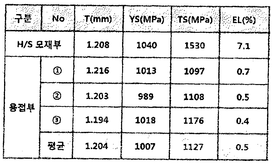
- Table 1 shows the results of the tensile test of the laser welded specimen in the direction perpendicular to the weld line without removing the plating layer.
- both the yield strength and the tensile strength of the welded portion were formed lower than that of the base material, and the elongation of the welded portion was less than 10% of the elongation of the base metal.
- Figure 3 is a view showing a tailored welded blank manufacturing method according to the present invention.
- the tailored blank manufacturing method according to the present invention is to weld the different types of blanks (10, 20) having a plating layer (14, 24) on the surface of the base material (12, 22) with a laser 30
- the filler wire 40, the filler wire 40, the base materials 12 and 22, and the plating layers 14 and 24 are made to mix in a weld joint part.
- the present invention is to control the composition of the weld joint by adjusting the component system of the filler wire 40 to be inserted into the weld joint to thereby have the weld joint has the desired physical properties.
- the base materials 12 and 22 may use a boron steel sheet material having hardenability, and the plating layers 14 and 24 may use an Al-Si plating layer or a Zn plating layer.
- the filler wire 40 should have a component system that prevents the formation of ferrite tissue in the range of 900 to 950 ° C. in consideration of the incorporation of the plating layers 14 and 24.
- the filler wire 40 is designed to have a higher content of the austenite stabilizing element than the component system of the plated steel plate base material, so that even if infiltration of the plating layer occurs, ferrite does not coexist in the weld joint at the hot stamping heating temperature. It must be possible to exist as a full austenite tissue.
- Figure 4 shows the shift of the transformation curve in accordance with the austenite stabilizing element content enhancement.
- austenite stabilizing elements for example, C, Mn, etc.
- the Ac3 temperature is lowered and the transformation curve is shifted to the right, resulting in an austenite loop.
- the austenite stabilizing element used in the present invention preferably contains C or Mn.
- the weld joint is present as a full austenite structure at a hot stamping heating temperature of 800 to 950 ° C., and when quenched, the weld joint is transformed into a full martensite structure.
- the austenitic stabilizing element is added to the filler wire, so that the microstructure of the weld joint has a full martensite structure after hot stamping.
- the hardness / strength can be prevented from being lowered, so that the welded fracture property can be prevented because the physical properties of the welded portion do not have a difference with the physical properties of the base material.
- the Mn content of the filler wire is preferably 1.5 to 7.0 wt% higher than the Mn content of the boron steel base material.
- the austenite loop increase is small, and the ferrite structure coexists in the weld joint at 800 to 950 ° C. If the Mn content is higher than the above range (above 7.0% by weight), the molten portion As the viscosity decreases and the expansion coefficient in the liquid phase transformation increases, problems may occur in the shape of the weld, and problems such as cracks in the weld may occur.
- the C content is preferably 0.1 to 0.8% by weight higher than the C content of the boron steel base material.
- the austenite loop increase is small, and the ferrite structure coexists in the weld joint at 800 to 950 ° C. If the C content is higher than the above range, the fracture occurs at the time of collision due to excessive hardness and strength of the weld. Let's do it.
- the present invention is manufactured by the same method as described above, the plated steel sheet blank having a different strength or different thickness is bonded by laser welding using a filler wire, the laser welding joint is present in austenite structure at 800 ⁇ 950 °C Provide a Taylor welded blank having a composition.
- the weld joint of the tailored welded blank according to the present invention does not occur in strength and hardness after hot stamping molding.
Landscapes
- Engineering & Computer Science (AREA)
- Physics & Mathematics (AREA)
- Optics & Photonics (AREA)
- Mechanical Engineering (AREA)
- Plasma & Fusion (AREA)
- Chemical & Material Sciences (AREA)
- Inorganic Chemistry (AREA)
- Laser Beam Processing (AREA)
- Body Structure For Vehicles (AREA)
Abstract
Description
표 1
[Table 1]
Claims (12)
- 이종강도 또는 이종두께를 가지는 도금 강판 블랭크를 필러 와이어를 사용하여 레이저 용접으로 접합하는 것을 특징으로 하는 테일러 웰디드 블랭크 제조방법.
- 제 1 항에 있어서,상기 필러 와이어는도금 강판의 도금층의 성분계의 혼입을 고려하여 용접 접합부가 800~950℃ 범위에서 페라이트 조직이 생성되지 않는 성분계를 가지는 것을 특징으로 하는 테일러 웰디드 블랭크 제조방법.
- 제 1 항에 있어서,상기 도금 강판은 Al-Si 도금층을 구비하며,상기 필러 와이어는 도금 강판 모재의 성분계보다 오스테나이트 안정화 원소의 함량이 많은 것을 특징으로 하는 테일러 웰디드 블랭크 제조방법.
- 제 3 항에 있어서,상기 오스테나이트 안정화 원소는 C 또는 Mn 을 포함하는 것을 특징으로 하는 테일러 웰디드 블랭크 제조방법.
- 제 4 항에 있어서,상기 필러 와이어의 C 함량은상기 도금 강판 모재의 C 함량보다 0.1~0.8 중량% 높은 것을 특징으로 하는 테일러 웰디드 블랭크 제조방법.
- 제 4 항에 있어서,상기 필러 와이어의 Mn 함량은상기 도금 강판 모재의 Mn 함량보다 1.5~7.0 중량% 높은 것을 특징으로 하는 테일러 웰디드 블랭크 제조방법.
- 이종강도 또는 이종두께를 가지는 도금 강판 블랭크가 필러 와이어를 사용하여 레이저 용접으로 접합되며, 상기 레이저 용접 접합부는 800~950℃ 에서 오스테나이트 조직으로 존재하는 조성을 가지는 것을 특징으로 하는 테일러 웰디드 블랭크.
- 제 7 항에 있어서,상기 용접 접합부는상기 도금 강판 모재와 도금층, 그리고 필러 와이어가 혼합된 조성을 가지는 것을 특징으로 하는 테일러 웰디드 블랭크.
- 이종강도 또는 이종두께를 가지는 도금 강판 블랭크가 필러 와이어를 사용하여 레이저 용접으로 접합되며, 상기 레이저 용접 접합부는 마르텐사이트 조직을 가지는 테일러 웰디드 블랭크를 핫스탬핑 가공하여 제조된 핫스탬핑 부품.
- 제 9 항에 있어서,상기 도금 강판 블랭크는경화능을 가지는 보론 강판을 모재로 하고, Al-Si 또는 Zn 도금층을 구비하는 것을 특징으로 하는 핫스탬핑 부품.
- 제 10 항에 있어서,상기 필러 와이어는상기 도금 강판 블랭크의 모재 보다 오스테나이트 안정화 원소의 함량이 높은 것을 특징으로 하는 핫스탬핑 부품.
- 제 11 항에 있어서,상기 오스테나이트 안정화 원소는 C 또는 Mn 을 포함하는 것을 특징으로 하는 핫스탬핑 부품.
Priority Applications (3)
| Application Number | Priority Date | Filing Date | Title |
|---|---|---|---|
| BR112013028391-2A BR112013028391B1 (pt) | 2012-12-03 | 2013-05-28 | Método para fabricar uma peça em bruto soldada por medida e componente estampado a quente |
| CN201380001259.1A CN104023899B (zh) | 2012-12-03 | 2013-05-28 | 拼焊板及其制造方法、以及使用拼焊板的热冲压部件 |
| JP2014551212A JP5873934B2 (ja) | 2012-12-03 | 2013-05-28 | テーラードブランクの製造方法 |
Applications Claiming Priority (2)
| Application Number | Priority Date | Filing Date | Title |
|---|---|---|---|
| KR1020120139035A KR101448473B1 (ko) | 2012-12-03 | 2012-12-03 | 테일러 웰디드 블랭크, 그 제조방법 및 이를 이용한 핫스탬핑 부품 |
| KR10-2012-0139035 | 2012-12-03 |
Publications (1)
| Publication Number | Publication Date |
|---|---|
| WO2014088170A1 true WO2014088170A1 (ko) | 2014-06-12 |
Family
ID=48520756
Family Applications (1)
| Application Number | Title | Priority Date | Filing Date |
|---|---|---|---|
| PCT/KR2013/004629 Ceased WO2014088170A1 (ko) | 2012-12-03 | 2013-05-28 | 테일러 웰디드 블랭크, 그 제조방법 및 이를 이용한 핫스탬핑 부품 |
Country Status (7)
| Country | Link |
|---|---|
| US (2) | US9381720B2 (ko) |
| EP (2) | EP3552754B1 (ko) |
| JP (1) | JP5873934B2 (ko) |
| KR (1) | KR101448473B1 (ko) |
| CN (1) | CN104023899B (ko) |
| BR (1) | BR112013028391B1 (ko) |
| WO (1) | WO2014088170A1 (ko) |
Cited By (3)
| Publication number | Priority date | Publication date | Assignee | Title |
|---|---|---|---|---|
| JP2016159359A (ja) * | 2015-03-05 | 2016-09-05 | Jfeスチール株式会社 | テーラードブランク熱間プレス部材 |
| WO2019102424A1 (en) | 2017-11-24 | 2019-05-31 | Arcelormittal | Method of producing a welded steel blank with the provision of a filler wire having a defined carbon content, associated welded blank, method of producing a welded part with hot press-formed and cooled steel part and associated part |
| TWI771066B (zh) * | 2021-06-18 | 2022-07-11 | 中國鋼鐵股份有限公司 | 離岸水下基礎用高強度鋼板銲接層裂之模擬試驗方法 |
Families Citing this family (58)
| Publication number | Priority date | Publication date | Assignee | Title |
|---|---|---|---|---|
| US20140062136A1 (en) * | 2012-09-06 | 2014-03-06 | GM Global Technology Operations LLC | Laser welded structural fender inner blank for mass optimization |
| CN105008087B (zh) * | 2012-10-24 | 2018-04-13 | 麦格纳国际公司 | 机动车部件中的焊缝的激光金属沉积熔覆 |
| DE102013012478A1 (de) * | 2013-07-26 | 2015-01-29 | GM Global Technology Operations LLC (n. d. Gesetzen des Staates Delaware) | Karosseriebauteil sowie Verfahren zur Herstellung eines Karosseriebauteils |
| DE102013108265B4 (de) * | 2013-08-01 | 2018-09-13 | Thyssen Krupp Steel Europe AG | Baugruppe von gehärteten Bauteilen und Verfahren zur Herstellung |
| WO2015162445A1 (fr) | 2014-04-25 | 2015-10-29 | Arcelormittal Investigación Y Desarrollo Sl | Procede et dispositif de preparation de toles d'acier aluminiees destinees a etre soudees puis durcies sous presse; flan soude correspondant |
| EP2942143B1 (en) | 2014-05-09 | 2017-03-15 | Gestamp HardTech AB | Methods for joining two blanks and blanks and products obtained |
| KR101638348B1 (ko) | 2014-06-18 | 2016-07-11 | 엔케이에스주식회사 | 핫 스탬핑용 도금강판의 접합방법 및 이를 이용하여 제작되는 테일러 웰디드 블랭크 |
| US10052720B2 (en) | 2014-09-17 | 2018-08-21 | Magna International Inc. | Method of laser welding coated steel sheets with addition of alloying elements |
| US10052721B2 (en) | 2014-09-17 | 2018-08-21 | Magna International Inc. | Method of laser welding coated steel sheets with addition of alloying elements |
| KR101637084B1 (ko) * | 2014-09-18 | 2016-07-06 | 부산대학교 산학협력단 | 필러와이어 및 이를 이용한 맞춤용접블랭크 제조방법 |
| EP3206831B1 (en) * | 2014-10-15 | 2020-05-06 | Autotech Engineering S.L. | Welding of steel blanks |
| KR101714121B1 (ko) | 2014-11-21 | 2017-03-09 | 현대자동차주식회사 | 테일러 웰디드 블랭크 제조방법 |
| KR102072860B1 (ko) * | 2016-04-29 | 2020-02-03 | 현대자동차주식회사 | 플래시버트 용접을 이용한 강판의 접합 방법 |
| KR20180089129A (ko) | 2017-01-31 | 2018-08-08 | 한국기계연구원 | 핫 스탬핑용 Al 합금 도금된 고강도강의 이종 재단용접을 위한 열처리 방법 |
| JP6679510B2 (ja) * | 2017-02-01 | 2020-04-15 | 豊田鉄工株式会社 | 車両用ピラー構成部材 |
| DE102017201674B3 (de) * | 2017-02-02 | 2018-03-29 | Ford Global Technologies, Llc | Verfahren zur Herstellung eines pressgehärteten Bauteils sowie Pressform |
| DE102017120611B4 (de) * | 2017-09-07 | 2020-06-25 | Wisco Tailored Blanks Gmbh | Verfahren und Vorrichtung zum Schmelzschweißen eines oder mehrerer Stahlbleche aus presshärtbarem Stahl |
| KR102410518B1 (ko) * | 2017-12-01 | 2022-06-20 | 현대자동차주식회사 | 테일러 웰디드 블랭크 제조방법 |
| CN108213711A (zh) * | 2018-01-12 | 2018-06-29 | 上海交通大学 | 一种用激光填丝焊工艺制造铝硅镀层热成形钢拼焊板的方法 |
| WO2019166852A1 (en) * | 2018-02-27 | 2019-09-06 | Arcelormittal | Method for producing a press-hardened laser welded steel part and press-hardened laser welded steel part |
| DE102018104829A1 (de) * | 2018-03-02 | 2019-09-05 | Voestalpine Automotive Components Linz Gmbh | Verfahren zur Schweißvorbehandlung beschichteter Stahlbleche |
| DE102018107291B4 (de) | 2018-03-27 | 2025-11-06 | Voestalpine Automotive Components Linz Gmbh | Verfahren zum Schweißen beschichteter Stahlbleche |
| CN112368105B (zh) * | 2018-06-27 | 2022-11-18 | 麦格纳国际公司 | 利用填充丝对涂覆的钢坯件进行激光焊接 |
| CN108838541B (zh) * | 2018-09-14 | 2020-07-24 | 苏州大学 | 一种汽车用冷轧钢板的激光焊接方法及其焊接接头 |
| KR20200040565A (ko) * | 2018-10-10 | 2020-04-20 | 현대자동차주식회사 | 동시성형 핫스탬핑 방법 및 핫스탬핑 제품 |
| CN109434384B (zh) * | 2018-11-16 | 2021-06-22 | 苏州普热斯勒先进成型技术有限公司 | 一种涂层钢板的制备方法及装置、热冲压方法 |
| US20220072658A1 (en) | 2018-12-24 | 2022-03-10 | Arcelormittal | Method for producing a welded steel blank and associated welded steel blank |
| US11583954B2 (en) * | 2019-03-04 | 2023-02-21 | Kabushiki Kaisha Toshiba | Welding method |
| CN111215751B (zh) * | 2019-03-29 | 2022-06-28 | 宝山钢铁股份有限公司 | 一种带铝或者铝合金镀层的钢制差强焊接部件及其制造方法 |
| DE102019108837A1 (de) * | 2019-04-04 | 2020-10-08 | Baosteel Tailored Blanks Gmbh | Verfahren zum Schmelzschweißen eines oder mehrerer Stahlbleche aus presshärtbarem Stahl |
| CN110587135B (zh) * | 2019-08-14 | 2021-09-24 | 上海宝钢阿赛洛激光拼焊有限公司 | 激光拼焊板焊缝防冲压开裂的焊接方法 |
| CN110666275A (zh) * | 2019-09-17 | 2020-01-10 | 凌云工业股份有限公司上海凌云汽车研发分公司 | 一种铝或铝合金镀层热成型钢的拼焊制造方法 |
| DE102019131906A1 (de) * | 2019-11-26 | 2021-05-27 | Voestalpine Automotive Components Linz Gmbh | Verfahren zum Verschweißen beschichteter Stahlbleche |
| DE102019131908A1 (de) | 2019-11-26 | 2021-05-27 | Voestalpine Automotive Components Linz Gmbh | Verfahren zum Verschweißen beschichteter Stahlbleche |
| CN111075807B (zh) * | 2019-12-16 | 2022-04-19 | 首钢集团有限公司 | 一种提升成形性能的激光拼焊板 |
| WO2021125577A1 (ko) * | 2019-12-20 | 2021-06-24 | 현대제철 주식회사 | 핫 스탬핑 부품, 및 이의 제조 방법 |
| CN111085587A (zh) * | 2019-12-24 | 2020-05-01 | 东莞市豪斯特热冲压技术有限公司 | 一种冲压工艺 |
| CN111112424A (zh) * | 2020-01-15 | 2020-05-08 | 安徽科正模具有限公司 | 一种汽车车架b柱热成型方法 |
| US11618098B2 (en) * | 2020-02-03 | 2023-04-04 | Ford Global Technologies, Llc | Methods of forming and stamping tailor friction stir welded blanks with enhanced edge stretch |
| KR102273869B1 (ko) | 2020-06-02 | 2021-07-06 | 현대제철 주식회사 | 알루미늄계 도금 블랭크, 이의 제조방법 및 알루미늄계 도금 블랭크 제조장치 |
| CN113967789B (zh) * | 2020-07-22 | 2025-09-12 | 中国科学院上海光学精密机械研究所 | 一种铝硅涂层钢的激光拼焊方法 |
| KR102308832B1 (ko) | 2020-10-29 | 2021-10-05 | 현대제철 주식회사 | 알루미늄계 도금 블랭크 및 이의 제조방법 |
| CN114434005B (zh) * | 2020-11-04 | 2024-08-13 | 中国科学院上海光学精密机械研究所 | 一种高强钢的激光焊接及热处理方法 |
| CN112589271B (zh) * | 2020-11-10 | 2022-01-11 | 东风汽车集团有限公司 | 一种激光拼焊板、拼焊冲压工件以及激光拼焊方法 |
| KR20220071545A (ko) | 2020-11-24 | 2022-05-31 | 현대자동차주식회사 | Twb 공법을 이용한 핫스탬핑 성형체 및 그 제조방법 |
| CN112455024B (zh) * | 2021-02-03 | 2021-04-27 | 育材堂(苏州)材料科技有限公司 | 激光拼焊预镀层钢板及其热冲压成形构件 |
| DE102021201334A1 (de) | 2021-02-12 | 2022-08-18 | Volkswagen Aktiengesellschaft | Verfahren zur Herstellung eines pressgehärteten Blechformteils sowie damit hergestelltes pressgehärtetes Blechformteil mit bereichsweise unterschiedlichen Eigenschaften |
| CN113118629A (zh) * | 2021-04-21 | 2021-07-16 | 攀钢集团攀枝花钢铁研究院有限公司 | 差强度激光拼焊板的制备方法 |
| KR102440343B1 (ko) | 2021-06-30 | 2022-09-05 | 현대제철 주식회사 | 알루미늄계 도금 블랭크 및 이의 제조방법 |
| KR102785702B1 (ko) * | 2021-08-05 | 2025-03-26 | 주식회사 포스코 | 테일러 웰디드 블랭크, 열간성형부재 및 이들의 제조방법 |
| CN115722795B (zh) | 2021-08-25 | 2024-09-10 | 宝山钢铁股份有限公司 | 一种钢制薄壁拼焊件的制造方法及使用该拼焊件制备的热冲压部件 |
| JP7747955B2 (ja) * | 2021-10-15 | 2025-10-02 | 日本製鉄株式会社 | テーラードブランク、熱間プレス成形品、テーラードブランクの製造方法、及び熱間プレス成形品の製造方法 |
| CN114346046A (zh) * | 2021-12-31 | 2022-04-15 | 潍坊倍力汽车零部件有限公司 | 一种片材内高压管件成型方法 |
| CN114952185B (zh) * | 2022-04-22 | 2024-06-04 | 一汽解放汽车有限公司 | 侧围加强件的成型方法 |
| CN117305563B (zh) * | 2022-06-22 | 2026-04-28 | 北京车和家汽车科技有限公司 | 拼焊板、拼焊板热成型部件及其制备方法和车辆 |
| KR20250000367A (ko) | 2023-06-26 | 2025-01-03 | (주) 동신모텍 | 핫프레스 포밍 방법 |
| WO2025182498A1 (ja) * | 2024-02-26 | 2025-09-04 | 日本製鉄株式会社 | 突合せ溶接継手、テーラードブランクおよび突合せ溶接継手の製造方法 |
| KR20250160753A (ko) | 2024-05-07 | 2025-11-14 | (주) 동신모텍 | 핫 스탬핑 프론트 필러 |
Citations (5)
| Publication number | Priority date | Publication date | Assignee | Title |
|---|---|---|---|---|
| JPH0557468A (ja) * | 1991-09-02 | 1993-03-09 | Toyota Motor Corp | 防錆鋼板のレーザ溶接方法 |
| JP2002283080A (ja) * | 2001-03-22 | 2002-10-02 | Japan Space Utilization Promotion Center | 鋼系材料とアルミニウム系材料との接合方法 |
| JP2003053566A (ja) * | 2001-08-15 | 2003-02-26 | Nippon Steel Weld Prod & Eng Co Ltd | 亜鉛メッキ層がある当接部のレーザ溶接方法 |
| JP2008055479A (ja) * | 2006-08-31 | 2008-03-13 | Jfe Steel Kk | 金属板の突合せ接合方法および接合金属板 |
| JP2010149160A (ja) * | 2008-12-26 | 2010-07-08 | Hitachi-Ge Nuclear Energy Ltd | 原子力発電プラント用炉心シュラウドの製造方法及び原子力発電プラント構造物 |
Family Cites Families (23)
| Publication number | Priority date | Publication date | Assignee | Title |
|---|---|---|---|---|
| DE3684331D1 (de) * | 1986-12-22 | 1992-04-16 | Thyssen Stahl Ag | Verfahren zum herstellen eines formkoerpers aus blechteilen unterschiedlicher dicke. |
| JP2002219589A (ja) | 2001-01-24 | 2002-08-06 | Mitsubishi Electric Corp | レーザビーム溶接装置及びレーザビーム溶接方法 |
| DE60236447D1 (de) * | 2001-10-23 | 2010-07-01 | Sumitomo Metal Ind | Verfahren zur heisspressbearbeitung von einem plattierten stahlprodukt |
| JP3738754B2 (ja) * | 2002-07-11 | 2006-01-25 | 日産自動車株式会社 | 電着塗装用アルミニウムめっき構造部材及びその製造方法 |
| JP3892782B2 (ja) | 2002-08-30 | 2007-03-14 | 新日本製鐵株式会社 | 耐塩酸性および耐硫酸性に優れた低合金鋼のガスシールドアーク溶接用ワイヤおよびそれを用いたガスシールドアーク溶接方法 |
| JP4188124B2 (ja) * | 2003-03-31 | 2008-11-26 | 独立行政法人物質・材料研究機構 | 焼き戻しマルテンサイト系耐熱鋼の溶接継手 |
| JP4498039B2 (ja) * | 2004-07-07 | 2010-07-07 | 株式会社神戸製鋼所 | レーザ・アーク複合溶接用ソリッドワイヤ及びレーザ・アーク複合溶接方法 |
| JP4889224B2 (ja) * | 2005-02-10 | 2012-03-07 | 日新製鋼株式会社 | テーラードブランク材の製造方法 |
| JP2007038269A (ja) | 2005-08-04 | 2007-02-15 | Nissan Motor Co Ltd | レーザ溶接方法 |
| JP4867319B2 (ja) * | 2005-12-05 | 2012-02-01 | 住友金属工業株式会社 | 熱間プレス用テーラードブランク材ならびに熱間プレス部材およびその製造方法 |
| WO2007118939A1 (fr) * | 2006-04-19 | 2007-10-25 | Arcelor France | Procede de fabrication d'une piece soudee a tres hautes caracteristiques mecaniques a partir d'une tole laminee et revetue |
| FR2903623B1 (fr) * | 2006-07-12 | 2008-09-19 | L'air Liquide | Procede de soudage hybride laser-arc de pieces metalliques aluminiees |
| WO2008110670A1 (fr) * | 2007-03-14 | 2008-09-18 | Arcelormittal France | Acier pour formage a chaud ou trempe sous outil a ductilite amelioree |
| DE102007015963A1 (de) * | 2007-04-03 | 2008-10-09 | Thyssenkrupp Steel Ag | Verfahren zum Herstellen von aus Stahlblechen bestehenden Flachprodukten, aus Stahlblechen zusammengesetztes Stahlflachprodukt und Strukturbauteil |
| WO2010085983A1 (en) * | 2009-02-02 | 2010-08-05 | Arcelormittal Investigacion Y Desarrollo S.L. | Fabrication process of coated stamped parts and parts prepared from the same |
| KR101149728B1 (ko) | 2009-07-21 | 2012-07-09 | 부산대학교 산학협력단 | 차량용 멤버 제작방법 |
| DE102010019258B4 (de) * | 2010-05-03 | 2014-12-11 | Thyssenkrupp Steel Europe Ag | Verfahren zur Herstellung maßgeschneiderter, warm umzuformender Stahlblechprodukte und Stahlblechprodukt |
| KR101035753B1 (ko) * | 2010-06-29 | 2011-05-20 | 현대제철 주식회사 | Twb 공법을 이용한 핫 스탬핑 성형체 및 그 제조 방법 |
| FR2962673B1 (fr) * | 2010-07-13 | 2013-03-08 | Air Liquide | Procede de soudage hybride arc/laser de pieces en acier aluminise avec fil a elements gamagenes |
| CN102259241A (zh) * | 2010-12-02 | 2011-11-30 | 江苏大学 | 一种低活化马氏体钢熔化焊用填充焊丝及使用方法 |
| WO2013014481A1 (fr) * | 2011-07-26 | 2013-01-31 | Arcelormittal Investigación Y Desarrollo Sl | Pièce d'acier soudée préalablement mise en forme à chaud à très haute résistance mécanique et procédé de fabrication |
| WO2013147035A1 (ja) * | 2012-03-28 | 2013-10-03 | 新日鐵住金株式会社 | ホットスタンプ用テーラードブランクおよびホットスタンプ部材ならびにそれらの製造方法 |
| JP5316670B1 (ja) * | 2012-04-17 | 2013-10-16 | 新日鐵住金株式会社 | ホットスタンプ用のテーラードブランクとその製造方法 |
-
2012
- 2012-12-03 KR KR1020120139035A patent/KR101448473B1/ko active Active
-
2013
- 2013-05-28 US US13/903,682 patent/US9381720B2/en active Active
- 2013-05-28 CN CN201380001259.1A patent/CN104023899B/zh active Active
- 2013-05-28 BR BR112013028391-2A patent/BR112013028391B1/pt active IP Right Grant
- 2013-05-28 JP JP2014551212A patent/JP5873934B2/ja active Active
- 2013-05-28 EP EP19177652.5A patent/EP3552754B1/en active Active
- 2013-05-28 EP EP13169439.0A patent/EP2737971A1/en not_active Ceased
- 2013-05-28 WO PCT/KR2013/004629 patent/WO2014088170A1/ko not_active Ceased
-
2015
- 2015-02-24 US US14/630,359 patent/US9884468B2/en active Active
Patent Citations (5)
| Publication number | Priority date | Publication date | Assignee | Title |
|---|---|---|---|---|
| JPH0557468A (ja) * | 1991-09-02 | 1993-03-09 | Toyota Motor Corp | 防錆鋼板のレーザ溶接方法 |
| JP2002283080A (ja) * | 2001-03-22 | 2002-10-02 | Japan Space Utilization Promotion Center | 鋼系材料とアルミニウム系材料との接合方法 |
| JP2003053566A (ja) * | 2001-08-15 | 2003-02-26 | Nippon Steel Weld Prod & Eng Co Ltd | 亜鉛メッキ層がある当接部のレーザ溶接方法 |
| JP2008055479A (ja) * | 2006-08-31 | 2008-03-13 | Jfe Steel Kk | 金属板の突合せ接合方法および接合金属板 |
| JP2010149160A (ja) * | 2008-12-26 | 2010-07-08 | Hitachi-Ge Nuclear Energy Ltd | 原子力発電プラント用炉心シュラウドの製造方法及び原子力発電プラント構造物 |
Cited By (4)
| Publication number | Priority date | Publication date | Assignee | Title |
|---|---|---|---|---|
| JP2016159359A (ja) * | 2015-03-05 | 2016-09-05 | Jfeスチール株式会社 | テーラードブランク熱間プレス部材 |
| WO2019102424A1 (en) | 2017-11-24 | 2019-05-31 | Arcelormittal | Method of producing a welded steel blank with the provision of a filler wire having a defined carbon content, associated welded blank, method of producing a welded part with hot press-formed and cooled steel part and associated part |
| US12269533B2 (en) | 2017-11-24 | 2025-04-08 | Arcelormittal | Method for producing a welded steel blank and associated welded blank |
| TWI771066B (zh) * | 2021-06-18 | 2022-07-11 | 中國鋼鐵股份有限公司 | 離岸水下基礎用高強度鋼板銲接層裂之模擬試驗方法 |
Also Published As
| Publication number | Publication date |
|---|---|
| US9884468B2 (en) | 2018-02-06 |
| EP2737971A1 (en) | 2014-06-04 |
| EP3552754B1 (en) | 2025-12-17 |
| JP5873934B2 (ja) | 2016-03-01 |
| CN104023899B (zh) | 2016-08-31 |
| EP3552754A1 (en) | 2019-10-16 |
| JP2015510453A (ja) | 2015-04-09 |
| CN104023899A (zh) | 2014-09-03 |
| US20150165726A1 (en) | 2015-06-18 |
| KR101448473B1 (ko) | 2014-10-10 |
| BR112013028391A2 (pt) | 2017-10-24 |
| KR20140071581A (ko) | 2014-06-12 |
| US20140154521A1 (en) | 2014-06-05 |
| BR112013028391B1 (pt) | 2019-04-24 |
| US9381720B2 (en) | 2016-07-05 |
Similar Documents
| Publication | Publication Date | Title |
|---|---|---|
| WO2014088170A1 (ko) | 테일러 웰디드 블랭크, 그 제조방법 및 이를 이용한 핫스탬핑 부품 | |
| WO2020130560A1 (ko) | 가공성이 우수한 냉연강판, 용융아연도금강판 및 이들의 제조방법 | |
| JP6505712B2 (ja) | 鋼板製品、この鋼板製品から製造される鋼部品、および自動車ボディ | |
| WO2012060496A1 (ko) | 열처리 경화 강판을 이용한 국부적으로 이종강도를 가지는 자동차 부품 제조방법 | |
| WO2009145563A2 (ko) | 열처리성이 우수한 초고강도 열간성형 가공용 강판, 열처리 경화형 부재 및 이들의 제조방법 | |
| WO2013047939A1 (ko) | 레이저 열처리를 이용한 이종강도를 갖는 강 제품 제조 방법 및 이에 이용되는 열처리 경화강 | |
| WO2013069937A1 (ko) | 온간프레스 성형용 강판, 온간프레스 성형 부재 및 이들의 제조방법 | |
| WO2022124609A1 (ko) | 연성 및 성형성이 우수한 고강도 용융아연도금강판 및 그 제조방법 | |
| WO2013002441A1 (ko) | 충돌성능이 우수한 열처리 경화강 및 이를 이용한 열처리 경화형 부품 제조 방법 | |
| WO2020111881A1 (ko) | 내식성 및 용접성이 우수한 열간 프레스용 알루미늄-철계 도금 강판 및 그 제조방법 | |
| WO2015099222A1 (ko) | 용접성 및 버링성이 우수한 열연강판 및 그 제조방법 | |
| WO2010074370A1 (ko) | 고강도 고연신 강판 및 열연강판, 냉연강판, 아연도금강판 및 아연도금합금화강판의 제조방법 | |
| WO2021045426A1 (ko) | 휠림 용접부 성형성이 우수한 플래시벗 용접부재 및 플래시벗 용접방법 | |
| WO2021100995A1 (ko) | 고강도 및 고성형성을 가지는 강판 및 그 제조방법 | |
| WO2014038759A1 (en) | Ferritic lightweight high-strength steel sheet having excelent stiffness and ductility, and method of manufacturing the same | |
| WO2020032446A1 (ko) | 강도 및 도금성이 우수한 저비중 클래드 강판 및 그 제조방법 | |
| US20240271238A1 (en) | Al-si coated press hardening component, a preparation method and use thereof | |
| KR20200007003A (ko) | 열간-성형 재료, 부품 및 용도 | |
| WO2018117650A1 (ko) | 표면부 nrl-dwt 물성이 우수한 극후물 강재 및 그 제조방법 | |
| WO2010074458A2 (ko) | 딥드로잉성이 우수하고 고항복비를 갖는 고강도 냉연강판, 이를 이용한 용융아연도금강판, 합금화 용융아연도금강판 및 이들의 제조방법 | |
| WO2020130614A2 (ko) | 구멍확장성이 우수한 고강도 열연강판 및 그 제조방법 | |
| WO2019066327A1 (ko) | 항복강도 및 드로잉성형성이 우수한 냉연강판 및 그 제조방법 | |
| WO2025127758A1 (ko) | 냉연강판 및 그 제조방법 | |
| WO2026095473A1 (ko) | 열간 성형 부품 및 이의 제조방법 | |
| WO2025127748A1 (ko) | 강판 및 그 제조방법 |
Legal Events
| Date | Code | Title | Description |
|---|---|---|---|
| ENP | Entry into the national phase |
Ref document number: 2014551212 Country of ref document: JP Kind code of ref document: A |
|
| REG | Reference to national code |
Ref country code: BR Ref legal event code: B01A Ref document number: 112013028391 Country of ref document: BR |
|
| 121 | Ep: the epo has been informed by wipo that ep was designated in this application |
Ref document number: 13860553 Country of ref document: EP Kind code of ref document: A1 |
|
| NENP | Non-entry into the national phase |
Ref country code: DE |
|
| 122 | Ep: pct application non-entry in european phase |
Ref document number: 13860553 Country of ref document: EP Kind code of ref document: A1 |
|
| REG | Reference to national code |
Ref country code: BR Ref legal event code: B01E Ref document number: 112013028391 Country of ref document: BR |
|
| ENP | Entry into the national phase |
Ref document number: 112013028391 Country of ref document: BR Kind code of ref document: A2 Effective date: 20131104 |