WO2014087782A1 - Dispositif d'ouverture/fermeture - Google Patents
Dispositif d'ouverture/fermeture Download PDFInfo
- Publication number
- WO2014087782A1 WO2014087782A1 PCT/JP2013/079974 JP2013079974W WO2014087782A1 WO 2014087782 A1 WO2014087782 A1 WO 2014087782A1 JP 2013079974 W JP2013079974 W JP 2013079974W WO 2014087782 A1 WO2014087782 A1 WO 2014087782A1
- Authority
- WO
- WIPO (PCT)
- Prior art keywords
- opening
- closing body
- closing
- engaged
- engaged portion
- Prior art date
Links
- 230000002265 prevention Effects 0.000 claims abstract description 46
- 238000000638 solvent extraction Methods 0.000 claims description 3
- 238000005096 rolling process Methods 0.000 description 9
- 238000004804 winding Methods 0.000 description 7
- 239000002184 metal Substances 0.000 description 4
- 230000003014 reinforcing effect Effects 0.000 description 4
- 238000003466 welding Methods 0.000 description 4
- 238000005192 partition Methods 0.000 description 2
- 230000002093 peripheral effect Effects 0.000 description 2
- 229920003002 synthetic resin Polymers 0.000 description 2
- 239000000057 synthetic resin Substances 0.000 description 2
- 230000005856 abnormality Effects 0.000 description 1
- 238000005452 bending Methods 0.000 description 1
- 239000000470 constituent Substances 0.000 description 1
- 230000007423 decrease Effects 0.000 description 1
- 230000000694 effects Effects 0.000 description 1
- 230000014509 gene expression Effects 0.000 description 1
- 230000002452 interceptive effect Effects 0.000 description 1
- 230000007257 malfunction Effects 0.000 description 1
Images


Classifications
-
- E—FIXED CONSTRUCTIONS
- E05—LOCKS; KEYS; WINDOW OR DOOR FITTINGS; SAFES
- E05D—HINGES OR SUSPENSION DEVICES FOR DOORS, WINDOWS OR WINGS
- E05D15/00—Suspension arrangements for wings
- E05D15/36—Suspension arrangements for wings moving along slide-ways so arranged that one guide-member of the wing moves in a direction substantially perpendicular to the movement of another guide member
- E05D15/38—Suspension arrangements for wings moving along slide-ways so arranged that one guide-member of the wing moves in a direction substantially perpendicular to the movement of another guide member for upwardly-moving wings, e.g. up-and-over doors
-
- E—FIXED CONSTRUCTIONS
- E05—LOCKS; KEYS; WINDOW OR DOOR FITTINGS; SAFES
- E05D—HINGES OR SUSPENSION DEVICES FOR DOORS, WINDOWS OR WINGS
- E05D13/00—Accessories for sliding or lifting wings, e.g. pulleys, safety catches
- E05D13/003—Anti-dropping devices
- E05D13/006—Anti-dropping devices fixed to the wing, i.e. safety catches
-
- E—FIXED CONSTRUCTIONS
- E05—LOCKS; KEYS; WINDOW OR DOOR FITTINGS; SAFES
- E05B—LOCKS; ACCESSORIES THEREFOR; HANDCUFFS
- E05B65/00—Locks or fastenings for special use
- E05B65/0021—Locks or fastenings for special use for overhead or roll-up doors, e.g. garage doors
-
- E—FIXED CONSTRUCTIONS
- E05—LOCKS; KEYS; WINDOW OR DOOR FITTINGS; SAFES
- E05D—HINGES OR SUSPENSION DEVICES FOR DOORS, WINDOWS OR WINGS
- E05D13/00—Accessories for sliding or lifting wings, e.g. pulleys, safety catches
- E05D13/10—Counterbalance devices
- E05D13/12—Counterbalance devices with springs
- E05D13/123—Counterbalance devices with springs with compression springs
- E05D13/1238—Counterbalance devices with springs with compression springs specially adapted for overhead wings
-
- E—FIXED CONSTRUCTIONS
- E05—LOCKS; KEYS; WINDOW OR DOOR FITTINGS; SAFES
- E05D—HINGES OR SUSPENSION DEVICES FOR DOORS, WINDOWS OR WINGS
- E05D13/00—Accessories for sliding or lifting wings, e.g. pulleys, safety catches
- E05D13/10—Counterbalance devices
- E05D13/12—Counterbalance devices with springs
- E05D13/1276—Counterbalance devices with springs with coiled ribbon springs, e.g. constant force springs
- E05D13/1292—Spring safety devices
-
- E—FIXED CONSTRUCTIONS
- E06—DOORS, WINDOWS, SHUTTERS, OR ROLLER BLINDS IN GENERAL; LADDERS
- E06B—FIXED OR MOVABLE CLOSURES FOR OPENINGS IN BUILDINGS, VEHICLES, FENCES OR LIKE ENCLOSURES IN GENERAL, e.g. DOORS, WINDOWS, BLINDS, GATES
- E06B1/00—Border constructions of openings in walls, floors, or ceilings; Frames to be rigidly mounted in such openings
- E06B1/04—Frames for doors, windows, or the like to be fixed in openings
- E06B1/52—Frames specially adapted for doors
- E06B1/522—Frames specially adapted for doors for overhead garage doors
-
- E—FIXED CONSTRUCTIONS
- E06—DOORS, WINDOWS, SHUTTERS, OR ROLLER BLINDS IN GENERAL; LADDERS
- E06B—FIXED OR MOVABLE CLOSURES FOR OPENINGS IN BUILDINGS, VEHICLES, FENCES OR LIKE ENCLOSURES IN GENERAL, e.g. DOORS, WINDOWS, BLINDS, GATES
- E06B3/00—Window sashes, door leaves, or like elements for closing wall or like openings; Layout of fixed or moving closures, e.g. windows in wall or like openings; Features of rigidly-mounted outer frames relating to the mounting of wing frames
- E06B3/32—Arrangements of wings characterised by the manner of movement; Arrangements of movable wings in openings; Features of wings or frames relating solely to the manner of movement of the wing
- E06B3/48—Wings connected at their edges, e.g. foldable wings
-
- E—FIXED CONSTRUCTIONS
- E05—LOCKS; KEYS; WINDOW OR DOOR FITTINGS; SAFES
- E05D—HINGES OR SUSPENSION DEVICES FOR DOORS, WINDOWS OR WINGS
- E05D15/00—Suspension arrangements for wings
- E05D15/16—Suspension arrangements for wings for wings sliding vertically more or less in their own plane
- E05D15/165—Details, e.g. sliding or rolling guides
-
- E—FIXED CONSTRUCTIONS
- E05—LOCKS; KEYS; WINDOW OR DOOR FITTINGS; SAFES
- E05Y—INDEXING SCHEME ASSOCIATED WITH SUBCLASSES E05D AND E05F, RELATING TO CONSTRUCTION ELEMENTS, ELECTRIC CONTROL, POWER SUPPLY, POWER SIGNAL OR TRANSMISSION, USER INTERFACES, MOUNTING OR COUPLING, DETAILS, ACCESSORIES, AUXILIARY OPERATIONS NOT OTHERWISE PROVIDED FOR, APPLICATION THEREOF
- E05Y2800/00—Details, accessories and auxiliary operations not otherwise provided for
- E05Y2800/40—Physical or chemical protection
- E05Y2800/41—Physical or chemical protection against finger injury
-
- E—FIXED CONSTRUCTIONS
- E06—DOORS, WINDOWS, SHUTTERS, OR ROLLER BLINDS IN GENERAL; LADDERS
- E06B—FIXED OR MOVABLE CLOSURES FOR OPENINGS IN BUILDINGS, VEHICLES, FENCES OR LIKE ENCLOSURES IN GENERAL, e.g. DOORS, WINDOWS, BLINDS, GATES
- E06B3/00—Window sashes, door leaves, or like elements for closing wall or like openings; Layout of fixed or moving closures, e.g. windows in wall or like openings; Features of rigidly-mounted outer frames relating to the mounting of wing frames
- E06B3/32—Arrangements of wings characterised by the manner of movement; Arrangements of movable wings in openings; Features of wings or frames relating solely to the manner of movement of the wing
- E06B3/48—Wings connected at their edges, e.g. foldable wings
- E06B3/485—Sectional doors
Definitions
- the present invention relates to an opening / closing device with a closing prevention device that prevents the opening / closing body from closing unexpectedly, and more particularly to an opening / closing device suitable as an overhead door.
- the opening / closing body (10) that opens and closes in the vertical direction, and projects from the opening / closing body in the lateral width direction and is rotatable to the opening / closing body.
- a supported roller member (12) that receives the roller member in a rollable manner and continues in the vertical direction, and is integrally provided on the opening / closing body and is movablely engaged with the guide rail.
- a closing prevention device (40) configured to engage and disengage the member (42), a biasing means (43: torsion coil spring) for biasing the movable engagement member in the locking direction, and a biasing of the biasing means
- an opening / closing device including a pulling member (33: wire or the like) that pulls the movable member upward against a force and pulls it away from the guide rail. According to this opening / closing device, if the tension of the traction member decreases due to, for example, the traction member (33) being cut or detached, or the mechanism for winding the traction member is damaged and idles.
- the movable engagement member (42) is rotated by the urging force of the urging means (43), and the brake engagement portion (42c: blade) of the movable member is digged into the guide rail (20), so that the opening / closing body ( 10) can be prevented from falling.
- the cover member (50) may increase the thickness of the entire guide rail or the cover member (50) may protrude indoors.
- an opening / closing body (overhead door 1) that opens and closes in the vertical direction, and projects from the opening / closing body in the lateral width direction and rotates to the opening / closing body.
- a roller member (rolling roller) supported so as to be able to be supported, a guide rail (2) which receives the roller member so as to be able to roll and continues in the vertical direction, and an engaged portion (engagement) fixed to the guide rail Member 9) and a locking mechanism (8) provided integrally with the opening / closing body and configured to engage and disengage the locking engagement portion (locking member 10) with respect to the engaged portion.
- a switchgear There is a switchgear.
- the locking engagement portion (locking member 10) engages / disengages with respect to the engaged portion (engaging member 9) at a position protruding from the opening / closing body surface to the indoor side.
- an object or the like may be sandwiched between the locking engagement portion and the engaged portion, or an object or the like may come into contact with the locking engagement portion.
- an object of the present invention is to provide an opening / closing device capable of preventing the periphery of the guide rail from becoming thick.
- One means for solving the above problems includes an opening / closing body that performs a closing operation in a partitioned manner, a roller member that protrudes from the opening / closing body in a lateral width direction and is rotatably supported by the opening / closing body, and the roller
- a guide rail that guides the member in the opening / closing body opening / closing direction, a support member that supports the guide rail in the opening / closing body opening / closing direction, an engaged portion fixed to a stationary part, and the opening / closing body are provided integrally.
- a closing prevention device configured to engage and disengage the braking engagement portion with respect to the engaged portion, and the closing prevention device engages the braking engagement portion with the engaged portion
- the opening / closing device configured to brake the closing operation of the opening / closing body
- a space adjacent to the lateral width direction end surface of the opening / closing body and continuous in the opening / closing body opening / closing direction is secured, and this space is defined as the lateral width direction end surface of the opening / closing body.
- said It surrounds over the opening and closing member opening and closing direction and by said support member Idoreru, in this space, wherein the placing the disengagement position and said brake engaging portion and the engaged portion.
- the present invention Since the present invention is configured as described above, it has a structure for preventing the braking engagement portion or the locking engagement portion from coming into contact with an object and the like, and the guide rail is thickened by the structure. Can be prevented.
- the first feature of the present embodiment is that an opening / closing body that performs a closing operation in a partitioning manner, a roller member that protrudes from the opening / closing body in a lateral width direction and is rotatably supported by the opening / closing body, and the roller
- a guide rail that guides the member in the opening / closing body opening / closing direction, a support member that supports the guide rail in the opening / closing body opening / closing direction, an engaged portion fixed to a stationary part, and the opening / closing body are provided integrally.
- a closing prevention device configured to engage and disengage the braking engagement portion with respect to the engaged portion, and the closing prevention device engages the braking engagement portion with the engaged portion
- the opening / closing device configured to brake the closing operation of the opening / closing body
- a space adjacent to the lateral width direction end surface of the opening / closing body and continuous in the opening / closing body opening / closing direction is secured, and this space is defined as the lateral width direction end surface of the opening / closing body.
- the guide It surrounds over the opening and closing member opening and closing direction by Le and said support member, in this space, said arranged disengagement portion between the engaged portion and the brake engagement portion.
- the space adjacent to the lateral end face of the opening / closing body is surrounded by the lateral end face of the opening / closing body, the guide rail, and the support member, and the engaged portion and the brake engaging portion are disposed in this space.
- the support member supports the guide rail on one end side in the opening / closing body thickness direction while facing the end face in the lateral width direction of the opening / closing body.
- the engagement portion and the braking engagement portion are formed in a L-shaped cross section including a piece portion and a cover piece portion protruding from the other end side in the opening / closing body thickness direction of the support piece portion toward the opening / closing body side.
- the engagement / disengagement portion is surrounded by an end face in the width direction of the opening / closing body, the guide rail, the support piece portion, and the cover piece portion. According to this feature, the engagement location between the braking engagement portion and the engaged portion can be covered with a more specific and simple configuration.
- the engaged portion is provided so as to protrude from the guide rail or the support member to the space side, and the brake In the space, the engaging portion has a position that can contact the engaged portion from the opening / closing body opening direction side and a position that cannot engage the engaging portion from the opening / closing body opening direction side. It is provided so that it may move between. According to this feature, the closing operation of the opening / closing body can be braked more effectively by bringing the braking engagement portion and the engaged portion into contact with each other.
- At least one of the engaged portion and the brake engaging portion is formed so as to be hooked and engaged with the other side. Has been. According to this feature, it is possible to reduce the fact that the engagement state is not ensured by being repelled by the reaction when the braking engagement portion comes into contact with the engaged portion.
- the closing prevention device includes a fixing member fixed to the opening / closing body side, a support member supported by the fixing member, and the braking mechanism.
- a movable member integrally having a joint portion, and the movable member is capable of engaging the brake engaging portion with the engaged portion, and the engaged portion.
- the brake engagement portion can be rotated with respect to the position where it cannot be engaged, and is maintained at the position where it cannot be engaged by being pulled by the pulling member from the opening / closing body opening direction side.
- the pulling member is provided so as to turn to the engageable position side by its own weight. According to this characteristic, when the tension
- the traction member is provided so as to pull the movable member obliquely from one side in the opening / closing body thickness direction, and the movable member is provided when the tension of the traction member is lost. It is provided so as to rotate from the one side to the other side by its own weight (see FIGS. 7 to 10).
- the pulling member is provided so as to pull the movable member obliquely from one side in the opening / closing body thickness direction, and the movable member loses the tension of the pulling member. At this time, it is provided so as to rotate from the other side to the one side with respect to the one side by its own weight (see FIGS. 15 to 21).
- an airtight means for preventing the space and the external space from communicating is provided between the opening / closing body and the support member. It was. According to this feature, the airtightness inside and outside the opening / closing body can be improved by the airtight means, and an object or the like is inserted between the opening / closing body and the support member, and the object or the like is engaged by braking. It is possible to prevent contact with the portion and the engaged portion.
- a space corresponding to the engagement / disengagement portion between the engaged portion and the braking engagement portion within the thickness of the opening / closing body Arranged. According to this feature, it is possible to more effectively prevent an object or the like from coming into contact with the braking engagement portion, and it is possible to make the periphery of the guide rail thinner.
- the engaged portion is the first engaged portion, and the second engaged portion is fixed to the immovable portion.
- a locking mechanism provided integrally with the opening / closing body and configured to engage and disengage the locking engagement portion with respect to the second engaged portion, and the locking engagement portion is moved by the locking mechanism.
- An opening / closing device engaged with a second engaged portion to lock the opening / closing body so as not to be opened, wherein the space includes a second engaged portion and a locking engaging portion.
- An engagement / disengagement place was arranged. According to this feature, an object or the like can be prevented from being sandwiched between the locking engagement part and the second engaged part, or the locking engagement part can be prevented from coming into contact with the object.
- the engagement / disengagement portion between the engaging portion and the second engaged portion is disposed in the space adjacent to the end surface in the lateral width direction of the opening / closing body, the number of members protruding in the opening / closing body thickness direction can be reduced. it can.
- the first engaged portion and the second engaged portion are a common portion, and the movable engaging portion is Both the locking engagement portions are engaged and disengaged. According to this feature, the first engaged portion and the second engaged portion can be shared, and the productivity of the switchgear can be improved.
- a space corresponding to the engagement / disengagement portion between the second engaged portion and the locking engagement portion within the thickness of the opening / closing body Arranged.
- the locking engagement portion is rotatably supported on the surface of the opening / closing body, and the free end side portion thereof is It is rotated in the space and engaged with and disengaged from the second engaged portion.
- the locking engagement portion includes a first piece portion extending in the lateral width direction of the opening / closing body along the surface of the opening / closing body, and the first piece.
- a second piece connected to the opening and extending in the thickness direction of the opening / closing body along the widthwise end face of the opening / closing body, and a third piece connected to the second piece and extending in the width direction of the opening / closing body And a part on the third piece part side is rotated along the opening / closing body thickness direction so as to be engaged and disengaged with respect to the second engaged part.
- the opening and closing body is linearly opened in the opening direction and then stored in the crossing direction with respect to the opening direction.
- An opening / closing device having a storage rail portion extending in the intersecting direction on an opening direction side of the guide rail, wherein a second engaged portion is provided in the storage rail portion, and the opening / closing body in an open state Has been locked so that it cannot be closed.
- one aspect of the present invention includes an opening / closing body that performs a closing operation in a partitioning manner, a roller member that protrudes from the opening / closing body in a lateral width direction and is rotatably supported by the opening / closing body, and the roller member.
- a guide rail that guides in the opening / closing body opening / closing direction, a support member that supports the guide rail in the opening / closing body opening / closing direction, an engaged portion fixed to a stationary part, and the opening / closing body are integrally provided and the A locking mechanism configured to engage and disengage the locking engagement portion with respect to the engaged portion, and by engaging the locking engagement portion with the engaged portion by the locking mechanism,
- an opening / closing device that locks so as not to move in an opening direction and / or a closing direction, a space that is adjacent to an end surface in the width direction of the opening / closing body and that is continuous in the opening / closing direction of the opening / closing body is secured.
- the Space adjacent to the lateral end face of the opening / closing body is surrounded by the lateral end face of the opening / closing body, the guide rail, and the support member, and the engaged portion and the locking engagement portion are disposed in this space.
- the “opening / closing body opening / closing direction” means a direction in which the opening / closing body slides in order to partition or open the space in the opening opened / closed by the opening / closing device.
- the “opening / closing body thickness direction” means the thickness direction of the opening / closing body in the fully closed state.
- the “opening / closing body width direction” or “opening / closing body width direction” means a direction that is substantially orthogonal to the opening / closing body opening / closing direction but not the thickness direction of the opening / closing body.
- the opening / closing device 1 of the present embodiment opens the opening / closing body 10 by sliding the opening / closing body 10 to the opening direction side (upward in the illustrated example), and further opens the opening / closing body 10 in a direction intersecting the opening direction (in the illustrated example). According to this, an example applied to an overhead door that is slid and stored obliquely upward) will be described.
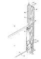
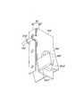
- the opening / closing device 1 has an opening / closing body 10 that closes and closes downward, protrudes from the opening / closing body 10 in the lateral width direction of the opening / closing body, and is rotatable to the opening / closing body 10.
- the roller member 20 supported by the guide member 30, the guide rail 30 that receives the roller member 20 from one side in the opening / closing body thickness direction so as to be able to roll (see FIG. 3), and continuous in the opening / closing body opening / closing direction.
- a support member 40 that supports the guide rail 30, a first engaged portion 51 (see FIG. 3) fixed to a stationary part (the support member 40 according to the illustrated example), and a second engaged portion. Part 52 (see FIG.
- a closing prevention device 60 that is provided integrally with the opening / closing body 10 and that is configured to engage / disengage the brake engaging part 62b with respect to the first engaged part 51, and an opening / closing It is provided integrally with the body 10 and the second It includes a locking mechanism 70 that is configured to disengage the locking engagement portion 71 with respect to the engaging portion 52, and a traction mechanism 80 to pull the closing member 10 from the opening and closing member opening direction side via the closing prevention device 60.
- the opening / closing device 1 When the opening / closing body 10 is suddenly closed due to the tension of the traction mechanism 80 being lost due to a malfunction of the traction mechanism 80, the opening / closing device 1 is provided with the braking engagement portion 62b of the closing prevention device 60. The closing operation of the opening / closing body 10 is braked by engaging with the first engaged portion 51. In addition, the opening / closing device 1 allows the locking engagement portion 71 of the locking mechanism 70 to be moved to the second covered state when the opening / closing body 10 is in a predetermined position (fully opened position and fully closed position according to an example of the present embodiment). The opening / closing body 10 is locked so as not to move in the opening direction and / or the closing direction by engaging with the engaging portion 52.
- the opening / closing device 1 is a space S that is adjacent to the end face in the width direction of the opening / closing body 10 and that continues in the opening / closing direction of the opening / closing body, and that corresponds to the thickness t of the opening / closing body 10 (see FIG. 3), the space S is continuously surrounded by the lateral end face of the opening / closing body 10, the guide rail 30 and the support member 40 in the opening / closing body opening / closing direction, and the first engaged portion is included in the space S. 51 and the braking engagement part 62b are arranged (see FIG. 3), and the engagement part between the second engaged part 52 and the locking engagement part 71 is also arranged in the space S. (See FIG. 12).
- the opening / closing body 10 is formed by connecting a plurality of substantially rectangular panel-like members 11 elongated in the width direction in the opening / closing direction so as to rotate between adjacent panel-like members 11, 11.
- the opening / closing body 10 opens and closes along the guide rail 30 via the roller members 12 supported at both ends in the lateral width direction.
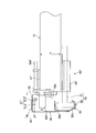
- a plurality of roller members 20 are disposed at predetermined intervals across the opening / closing body opening / closing direction on the end side in the lateral width direction of the opening / closing body 10 and are rotatably supported.
- the lowermost roller member 20 is rotatably supported by a closing prevention device 60 described later.
- Each roller member 20 is configured to support a substantially donut-shaped rolling element 22 on the tip side of a shaft portion 21 extending in the lateral direction of the opening / closing body.
- the roller member 20 is configured to rotate the shaft portion 21 and the rolling element 22 integrally.
- the roller member 20 is configured so that the rolling element 22 is attached to the shaft portion 21. It is also possible to adopt a mode in which it is rotatably supported. 3 to 4, the roller member 20 is supported by the closing prevention device 60.
- the closing prevention device 60 in the opening and closing body 10 like the upper roller member 20 shown in FIG. It can be provided in a part or in a part other than the illustrated example.
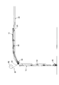
- the guide rail 30 includes an opening / closing rail portion 31 extending in the opening / closing direction of the opening / closing body 10 and a storage rail portion 32 for storing the opening / closing body 10 when opened in a direction intersecting the opening / closing direction (in the illustrated example, obliquely upward). And a corner rail portion 33 that connects the open / close rail portion 31 and the storage rail portion 32 in a smooth curved shape, and the rail portions 31, 33, and 32 extend in the direction of extension of the roller.
- the rolling element 22 of the member 20 is formed in a substantially concave shape (see FIG. 3) so as to cover the rolling element 22 in a rotatable manner.
- the surface on the outdoor side (upper side in FIG.
- the indoor side (lower side in FIG. 3) of the opening / closing body thickness direction inside the guide rail 30 covers the outer peripheral side of the rolling element 22 in a substantially concave curved shape so that the rolling element 22 is not dropped. It is a concave curved part 30b to prevent.
- this guide rail 30 is fixedly supported by the supporting member 40 mentioned later by fixing means, such as welding.
- the indoor side and the outdoor side are expressions for convenience in order to facilitate understanding, and the indoor side refers to the side where the closing prevention device 60 is fixed to the opening / closing body 10 in the opening / closing body thickness direction.
- the outdoor side means the side opposite to the indoor side in the opening / closing body thickness direction.
- the position where the closing prevention device 60 is provided is not limited to the indoor side, and the closing prevention device 60 may naturally be arranged outside the room or house depending on the purpose of use of the opening / closing device 1 or the like.
- the closing prevention device 60 may be provided in a place where there is no concept of a room or the like, for example, as a substitute for a simple passage partition or a gate in an external space, instead of being provided in a room or a house.
- the support member 40 is a member that is fixedly fixed to a building, a column, or the like on which the opening / closing device 1 is installed, and supports the guide rail 30 continuously in the opening / closing body opening / closing direction.
- the support member 40 includes a flat support piece 41 that supports and fixes the guide rail 30 on one end side in the open / close body thickness direction opposite to the lateral width direction end face of the open / close body 10, and the open / close body in the support piece 41. It is formed in an L-shaped cross section including a flat surface-like cover piece portion 42 that protrudes from the other end side in the thickness direction to the opening / closing body 10 side (right side according to FIG. 3).
- An airtight means 90 is provided between the support member 40 and the opening / closing body 10.
- the airtight means 90 is fixed to the support member 40 at the base end side, and the free end is brought into contact with the surface on the outdoor side of the opening / closing body 10 so that the space S in the support member 40 communicates with the external space. Is blocked.
- the airtight means 90 is fitted to a fixing piece 91 made of metal having a substantially L-shaped cross section fixed to the support member 40 and the protruding end side of the fixing piece 91 in the opening / closing body width direction.
- the connecting member 92 is made of a synthetic resin that is fixed together, and an elastic hermetic member 93 made of a synthetic resin supported by the connecting member 92.
- the elastic airtight member 93 is pressed against the opening / closing body 10 by the elastic force of the fixing piece 91 in the bending direction, and the elastic airtight member 93 is elastically deformed to contact the surface of the opening / closing body 10. Increase area. Therefore, the airtightness between the end of the opening / closing body 10 in the width direction and the support member 40 can be improved. In addition, since the gap between the support member 40 and the opening / closing body 10 is closed, it is possible to prevent an object or the like from being inserted into the space S through the gap.
- the space S is a space continuous in the opening / closing body opening / closing direction that is surrounded on all sides by the end of the opening / closing body 10 in the lateral width direction, the portion having the receiving surface 30a of the guide rail 30, and the support member 40. .
- This space S is provided in a range adjacent to the end face of the opening / closing body 10 in the width direction and corresponding to the thickness t of the opening / closing body 10. If it demonstrates more concretely, this space S will be ensured between two virtual surface A1, A2 which extended the outdoor side surface and the indoor side back surface of the opening-and-closing body 10 to the support member 40 side.
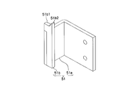
- the first engaged portion 51 is a portion that is engaged / disengaged by the brake engaging portion 62b. More specifically, as shown in FIGS. 5 and 6, the L-shaped portion that is fixed to the inner surface of the support member 40. An angle-shaped fixed piece 51a and a protruding piece 51b connected to the fixed piece 51a and projecting toward the opening / closing body opening direction from the fixed piece 51a Accordingly, it is formed in a substantially concave shape in plan view. A plurality of the first engaged portions 51 are provided at intervals in the vertical direction, and each of them is fixed to the support piece portion 41.
- the means for fixing the fixed piece 51a to the support member 40 is riveted or screwed, but may be other fastening means such as welding or fitting. .
- the fixed piece part 51a should just be fixed to the fixed part, and as another example, you may make it fix the fixed piece part 51a to the guide rail 30 or other fixed members not shown.
- the projecting piece 51b is a plate-like portion that is disposed substantially parallel to the opening / closing body thickness direction (in accordance with FIG. 6 with the fixed piece 51a) and extends to the outdoor side, and its opening / closing body opening direction It has a receiving surface 51b1 that receives a braking engagement portion 62b, which will be described later, and a protrusion 51b2 that protrudes from the receiving surface 51b1 in the opening / closing body opening direction, and is formed in a substantially hook shape. Then, when the braking engagement portion 62b comes into contact with the receiving surface 51b1, the protruding piece portion 51b engages with the braking engagement portion 62b so as to cover the protrusion 51b2 in a hook shape from below (see FIG. 8).
- the closing prevention device 60 includes a fixing member 61 fixed to the opening / closing body 10 side, and a movable member 62 that is supported by the fixing member 61 and integrally includes a brake engaging portion 62b (FIG. 3). And FIG. 4).
- the fixing member 61 is a member fixed and fixed to the opening / closing body 10, and the shaft portion 21 of the roller member 20 is rotatably inserted and supported in a cylindrical portion 61a inserted in the opening / closing body lateral width direction. Yes.
- the movable member 62 has an engageable position (see FIGS. 8 and 10) at which the brake engaging portion 62b can be engaged with the first engaged portion 51, and the first engaged portion 51.
- the brake engaging portion 62b can be engaged with an unengageable position (see FIGS. 7 and 9), and the traction member of the traction mechanism 80 can be opened from the opening / closing body opening direction side. By being pulled by 83, it is maintained at the non-engageable position, and when the tension of the pulling member 83 is lost, it is configured to turn to the engageable position side by its own weight.
- the movable member 62 includes a movable main body 62a formed in a substantially concave shape that fits into a substantially convex fixed member 61 that protrudes indoors in the opening / closing body thickness direction, and the movable main body 62a. And a braking engagement portion 62b protruding into the space S along the lateral width direction of the opening / closing body from the side surface of the portion 62a.
- reference numeral 62 d is a reinforcing rib that prevents the side portion of the movable main body portion 62 a from being bent by the tension of the pulling member 83.
- the movable main body 62a is pivotally supported with respect to the fixed member 61 via the shaft member 61b, and its pivot point is biased toward one side in the opening / closing body thickness direction (in FIG. 9, indoor (right) side). It is arranged at the position.
- the movable main body 62a is pulled by the pulling member 83 on the other side in the opening / closing body thickness direction from the pivot point (outdoor (left) side according to FIG. 9) and closer to the lower end.
- the to-be-towed part 62c is projected.
- the braking engagement portion 62b is a rectangular plate-like member, and is fixed to the side surface of the movable main body portion 62a in the vertical direction by a fixing means such as welding.
- the lower end portion of the braking engagement portion 62b has a contact surface 62b1 that is in contact with the first engaged portion 51 and a protrusion 62b2 that protrudes downward from the contact surface 62b1. It is formed in a substantially hook shape.
- the brake engaging portion 62b covers the protrusion 62b2 in a hook shape from above on the receiving surface 51b1. (See FIGS. 7 and 8).
- the second engaged portion 52 is disposed in the space S, and is a metal member having an L-shaped cross section that is fixed to a non-moving portion (the guide rail 30 according to the illustrated example). It is.
- the second engaged portion 52 includes a concave portion 52b1 that is engaged with and disengaged by a locking engagement portion 71 of a locking mechanism 70, which will be described later, and a concave portion 52b1 that protrudes in the opening / closing body thickness direction. And an inclined surface 52a2 inclined in a mountain shape.
- the concave portion 52b1 is formed in a concave shape having a width slightly larger than the vertical width of the locking engagement portion 71.
- the inclined surface 52a2 prevents the locking engagement portion 71 from flapping due to vibration during the opening / closing operation of the opening / closing body 10 and being unexpectedly locked to the upper and lower ends of the one piece portion 52a.
- the second engaged portion 52 has a position facing the locking engagement portion 71 when the opening / closing body 10 is fully closed and a position facing the locking engagement portion 71 when the opening / closing body 10 is fully opened. It is provided at two places (see FIG. 13). As another example, it may be provided at a position facing the locking engagement portion 71 in an open state. Further, as another example, in FIG. 13, either the fully engaged second engaged portion 52 or the fully closed second engaged portion 52 is omitted, or the opening / closing device 1 is omitted. The number and position can be changed according to the purpose of use.
- the locking mechanism 70 includes a locking engagement portion 71 that rotates in the opening / closing body thickness direction and engages / disengages with the second engaged portion 52, and each locking engagement portion 71.
- a support member 72 that rotatably supports the locking engagement portion 71, a string-like member 73 connected to one end of the locking engagement portion 71, a tension operation portion 74 connected to the other end of the string-like member 73, and the like. Yes.
- the locking engagement portion 71, the support member 72, the string-like member 73, and the like are provided symmetrically with respect to the opening / closing body 10 (see FIG. 1).
- the locking engagement portion 71 is connected to the first piece portion 71 a extending in the lateral width direction of the opening / closing body along the surface of the opening / closing body 10, and is opened / closed along the widthwise end surface of the opening / closing body 10. It has a substantially crank shape in plan view including a second piece 71b extending in the body thickness direction and a third piece 71c connected to the second piece 71b and extending in the lateral width direction of the opening / closing body.
- the base end side (the right end side according to FIG. 12) of the first piece 71a is rotatably supported by a support member 72 described later.
- One end side of a string-like member 73 (for example, a metal wire or the like) extending in the lateral width direction of the opening / closing body is fastened to the second piece 71b.
- the third piece 71c is formed so as to be engaged with and disengaged from the second engaged portion 52 in a concavo-convex shape by turning in the opening / closing body thickness direction.
- the support member 72 includes a shaft portion 72a that rotatably supports the locking engagement portion 71, a support portion 72b that supports the shaft portion 72a and is fixed to the surface of the opening / closing body 10, and is provided integrally with the support portion 72b. And a urging member 72 d for urging the locking engagement portion 71 in the engagement direction with respect to the second engaged portion 52.
- the restricting portion 72c is positioned on the distal end side (free end side) of the locking engagement portion 71 with respect to the shaft portion 72a, and when the locking engagement portion 71 is rotated in a direction away from the opening / closing body 10, the amount of rotation is limited. By restricting, the locking engagement portion 71 is prevented from being locked to the upper end or the lower end of the second engaged portion 52. That is, if the configuration without the restricting portion 72c is used, the locking engagement portion 71 flutters in the opening / closing body thickness direction by vibration during the opening / closing operation, and is locked to the upper end and the lower end of the second engaged portion 52. There is a risk that. However, according to the present embodiment, the amount of rotation (the fluttering) of the locking engagement portion 71 is restricted by the restricting portion 72c, so that the above-described problems can be prevented.
- the biasing member 72d is a torsion coil spring wound around the shaft portion 72a. One end side of the biasing member 72d is fastened to the locking engagement portion 71 and the other end side is fastened to the support portion 72b. is doing.
- the urging member 72 d urges the locking engagement portion 71 to rotate in the direction of engagement with the second engaged portion 52.
- the urging member 72d can be replaced with a member of another form such as a tension spring provided between the first piece 71a and the opening / closing body 10.
- the string-like member 73 connects the other end side with respect to the one end side fastened to the locking engagement part 71 to the tension operation part 74 (refer FIG. 1).
- the pulling operation unit 74 is configured to rotate between a state where the string-like member 73 is not pulled and a state where the string-like member 73 is pulled and locked. Therefore, in a state where the string-like member 73 is not pulled by the pulling operation portion 74, the locking engagement portion 71 is rotated toward the second engaged portion 52 side by the urging force of the urging member 72d. Further, when the string-like member 73 is pulled and locked by the pulling operation portion 74, the locking engagement portion 71 rotates and separates from the second engaged portion 52.
- the traction mechanism 80 includes a shaft portion 81 disposed across the opening / closing body width direction on the opening direction side of the opening / closing body 10, reel portions 82 and 82 supported on both ends of the shaft portion 81, and A pulling member 83 wound or unwound by the reel portion 82 and pulling sources 84 and 84 for urging the shaft portion 81 so as to wind the pulling member 83 by the reel portion 82 are provided (see FIG. 1). ).
- the shaft portion 81 is disposed in the width direction of the opening / closing body so as to be positioned on the upper extension line of the opening / closing body 10 in the fully closed state, and each of both end sides thereof is a stationary portion (for example, the opening / closing device 1). It is rotatably supported via a bearing bracket or the like with respect to a housing or the like to be installed.
- Each reel portion 82 is a substantially cylindrical member capable of winding and unwinding the pulling member 83, and its central portion is fixed to one end side of the shaft portion 81.
- the pulling member 83 is a metal wire, and its end on the opening / closing body opening direction side is fastened to the outer peripheral surface of the reel section 82, and its end on the opening / closing body closing direction side is It is fixed to the movable member 62.
- the traction source 84 is a spring that winds the shaft portion 81 in the winding direction by fixing one end side to the shaft portion 81 and fixing the other end side to the immovable portion.
- a mechanism in which the shaft portion 81 is rotated in the winding rotation direction by the weight of the weight member, and the shaft portion 81 is rotated in the winding rotation direction by the power of an electric motor or the like It is also possible to use a mechanism or the like.
- the locking engagement portion 71 of the locking mechanism 70 is not engaged with the second engaged portion 52.
- the movable member 62 of the closing prevention device 60 is pulled by the pulling member 83 against its own weight, so that the disengageable position (see FIGS. 7 and 7). 9). Therefore, the opening / closing body 10 performs an opening / closing operation and a storage operation without receiving a braking force from the closing prevention device 60.
- the traction member 83 may be damaged by troubles on the traction mechanism 80 side such as cutting of the traction member 83, idle rotation of the reel portion 82 that winds up the traction member 83, idle rotation of the traction source 84 that urges the reel portion 82 in the winding direction.
- the tension is lowered, as shown in FIGS. 8 and 10, the movable member 62 is rotated indoors (counterclockwise in the illustrated example) by its own weight. Then, the braking engagement portion 62b of the movable member 62 becomes an engageable position facing the protruding piece portion 51b of the first engaged portion 51 in the vertical direction.
- the braking engagement portion 62b is in contact with the first engaged portion 51, so that the rapid lowering of the opening / closing body 10 can be stopped. More specifically, at the time of the contact, the contact surface 62b1 of the braking engagement portion 62b and the projection 62b2 are simultaneously engaged with the receiving surface 51b1 of the first engaged portion 51 in a hook shape. The receiving surface 51b1 and the protrusion 51b2 of the first engaged portion 51 are also engaged with the contact surface 62b1 of the brake engaging portion 62b in a hook shape. For this reason, it is possible to prevent the braking engagement portion 62b from being bounced and disengaged due to an impact or reaction during the contact.
- the brake engaging portion 62 b and the first engaged portion 51 are arranged such that the lateral end of the opening / closing body 10, the guide rail 30, the support member 40, and the airtight means 90. Therefore, it is possible to prevent an object or the like from being caught between these engagement portions or an object or the like from contacting the braking engagement portion 62b or the first engaged portion 51.
- the brake engaging part 62b and the 1st to-be-engaged part 51 are arrange
- the distal end side portion (specifically, part of the third piece 71c and the second piece 71b) of the locking engagement portion 71 is in the space S. Has been placed.
- the string-like member 73 is loosened by operating the pulling operation portion 74 at the fully closed position of the opening / closing body 10
- the locking engagement portion 71 is rotated indoors in the space S by the biasing member 72d.
- the second engaged portion 52 is engaged in a concavo-convex shape, and the opening / closing body 10 is locked so as not to be opened and closed.
- the locking engagement portion 71 and the second engaged portion 52 are surrounded by the lateral width end of the opening / closing body 10, the guide rail 30, the support member 40, and the airtight means 90, It is possible to prevent an object or the like from being caught in the object, or an object or the like from coming into contact with the locking engagement portion 71 or the second engaged portion 52.
- the locking state at the fully closed position and the fully open position is such that if the string-like member 73 is pulled by the operation of the pulling operation portion 74, the locking engagement portion 71 rotates in the reverse direction, and the second engaged state. Since it comes off from the joint portion 52, it can be released.
- the pulling operation unit 74 In the fully opened position, the position of the pulling operation unit 74 is high, and there is a possibility that the operation with respect to the pulling operation unit 74 may be difficult. Therefore, if necessary, the pulling operation unit 74 may be extended by a member extending downward. You may add the mechanism etc. to operate.
- the opening / closing device 2 shown in FIGS. 1, 14 to 20 replaces the opening / closing device 1 by replacing the first engaged portion 51 with the first engaged portion 51 ′ and closing the closing prevention device 60.
- the prevention device 60 ′ is replaced.
- the first engaged portion 51 ′ is a portion that is engaged and disengaged by the braking engagement portion 62 b ′ of the closing prevention device 60 ′.
- the support member 40 A flat fixed piece 51a ′ fixed to the inner surface, and a protruding piece connected to the fixed piece 51a ′ and protruding from the fixed piece 51a ′ toward the opening / closing body opening direction.
- the portion 51b ' is formed and has a substantially L-shaped cross section according to the illustrated example.
- a plurality of the first engaged portions 51 ′ are provided at intervals in the vertical direction, and each of them is fixed to the cover piece portion 42 of the support piece portion 41 (see FIG. 14).
- the projecting piece 51 b ′ is a plate-like portion disposed substantially in parallel with the opening / closing body thickness direction, and has a braking engagement at the end on the opening / closing body opening direction side. It has a receiving surface 51b1 ′ for receiving the portion 62b ′ and a protrusion 51b2 ′ protruding from the receiving surface 51b1 ′ in the opening / closing body opening direction, and is formed in a substantially hook shape.
- the projecting piece 51b ′ is configured so that the protrusion 51b2 ′ is covered with a hook from the lower side with respect to the braking engagement portion 62b ′ when the braking engagement portion 62b ′ contacts the receiving surface 51b1 ′. Engage (see FIG. 20).
- the closing prevention device 60 ′ includes a fixing member 61 ′ fixed to the opening / closing body 10 side, and a brake engaging portion 62b ′ supported by the fixing member 61 ′. And a movable member 62 ′ integrally therewith.
- the fixed member 61 ′ is a member that is fixedly fixed to the surface of the opening / closing body 10 (the surface on the outdoor side, see FIG. 14). It is pivotably supported.
- the movable member 62 ′ has an engageable position (see FIG. 20) at which the brake engaging portion 62b ′ can be engaged with the first engaged portion 51 ′, and the first engaged portion 51.
- the traction member 83 of the traction mechanism 80 can be rotated from an unengageable position (see FIG. 19) where it is impossible to engage the braking engagement portion 62b with respect to the opening / closing body opening direction side. When the tension of the pulling member 83 is lost, it is configured to rotate to the engageable position side by its own weight.
- the movable member 62 ′ includes a movable main body 62a ′ that is rotatably supported by a fixed member 61 ′ via a shaft 62d ′, and a side surface of the movable main body 62a ′. And a braking engagement portion 62b ′ protruding into the space S along the lateral width direction of the opening / closing body.
- the movable main body 62a ′ is pivotally supported with respect to the fixed member 61 ′ via a shaft portion 62d ′, and its pivot point (center of the shaft portion 62d ′) is set to one side in the opening / closing body thickness direction (see FIG. 19). According to this, it is arranged at a position biased to the outdoors (left side).
- the movable main body 62a ′ is pulled by the pulling member 83 on the other side in the opening / closing body thickness direction from the pivot point (indoor (right) side according to FIG. 19) and closer to the lower end.
- the to-be-towed part 62c is projected.
- the braking engagement portion 62b ' is fixed to the side surface of the movable main body portion 62a' by fixing means such as welding, and protrudes from the side surface in the lateral direction of the opening / closing body.
- the brake engaging portion 62b ′ is formed in a substantially wedge shape (see FIG. 15) having a narrow width toward the lower side, and a first engaged portion 51 ′ is formed at the lower end portion thereof.
- a protrusion 62b2 ′ protruding from the corresponding contact surface 62b1 ′ in the opening / closing body closing direction, and the protruding end side is formed in a substantially hook shape.
- the braking engagement portion 62b ′ has a protrusion 62b2 ′ from above with respect to the receiving surface 51b1 ′ when the abutting surface 62b1 ′ contacts the receiving surface 51b1 ′ of the first engaged portion 51 ′. Are engaged with each other in a hook shape (see FIG. 20).
- the roller member 20 is rotatably supported by the opening / closing body 10 so as not to interfere with the closing prevention device 60.
- the movable member 62 ′ of the closing prevention device 60 ′ resists its own weight during the normal opening / closing operation and storage operation of the opening / closing body 10. By being pulled by the pulling member 83, it is maintained at the disengageable position (see FIG. 19).
- the traction member 83 may be damaged by troubles on the traction mechanism 80 side such as cutting of the traction member 83, idle rotation of the reel portion 82 that winds up the traction member 83, idle rotation of the traction source 84 that urges the reel portion 82 in the winding direction.
- the tension is lowered, as shown in FIG. 20, the movable member 62 ′ is rotated to the outdoor side (clockwise in the illustrated example) by its own weight. Then, the braking engagement portion 62b ′ of the movable member 62 ′ becomes an engageable position facing the protruding piece portion 51b ′ of the first engaged portion 51 ′.
- the braking engagement portion 62b ′ abuts on the first engaged portion 51 ′, and the rapid lowering of the opening / closing body 10 can be stopped. More specifically, the contact surface 62b1 'and the protrusion 62b2' of the braking engagement portion 62b 'are hooked to the receiving surface 51b1' of the first engaged portion 51 'during the contact. At the same time, the receiving surface 51b1 ′ and the projection 51b2 ′ of the first engaged portion 51 ′ are engaged with the contact surface 62b1 ′ of the brake engaging portion 62b ′ in a hook shape. Therefore, it is possible to prevent the braking engagement portion 62b 'from being bounced and not engaged by an impact or reaction during the contact.
- the braking engagement portion 62 b ′ and the first engaged portion 51 ′ are surrounded by the lateral width end of the opening / closing body 10, the guide rail 30, and the support member 40. Since the object is located in the space S, the object or the like may be caught between these engagement points, or the object or the like may come into contact with the braking engagement part 62b ′ or the first engaged part 51 ′. Can be prevented.
- the width of the opening / closing body 10 is reduced.
- the number of members protruding in the opening / closing body thickness direction can be reduced, and as a result, the structure around the guide rail 30 can be made relatively thin.
- the airtight means 90 is omitted.
- the airtight means 90 is added in the same manner as the opening / closing device 1, and the object is added to the braking engagement portion 62b ′ and the first engaged portion 51 ′. Etc. may be more effectively prevented from contacting.
- the 1st to-be-engaged part 51 (or 51 ') and the 2nd to-be-engaged part 52 were each a separate member, as another preferable form, as 1st
- the engaged portion 51 (or 51 ′) and the second engaged portion 52 are made to be a common member or part having the same shape, whereas the braking engagement portion 62b (or 62b ′) and the locking engagement portion 71 may be engaged and disengaged.
- the 1st to-be-engaged part 51 (or 51 ') and the 2nd to-be-engaged part 52 were fixed to the guide rail 30 or the support member 40
- the engaged portion 51 (or 51 ′) and the second engaged portion 52 can be formed integrally with the guide rail 30 or the support member 40.
- a guide rail 30 ′ shown in FIG. 21 is formed by forming an engaged portion 31 ′ that can be the first engaged portion and the second engaged portion on the guide rail 30 ′ itself. is there.
- Each engaged portion 31 ′ is a concavo-convex portion provided in the guide rail 30 ′ at a position facing the braking engagement portion 62 b and / or the locking engagement portion 71 at intervals in the vertical direction.
- the brake engaging portion 62b is brought into contact with and locked on the upper surface of the convex portion constituting the engaged portion 31 ′.
- the locking engagement part 71 fits into the recessed part which comprises engaged part 31 ', and is latched.
- the 1st to-be-engaged part 51 and the 2nd to-be-engaged part 52 were provided with two or more along the guide rail 30, as these examples, these 1st to-be-engaged parts are provided.
- One or both of 51 and the second engaged portion 52 may be singular.
- the 2nd to-be-engaged part 52 was formed in concave shape so that the locking engagement part 71 of a locked state might not move to both an opening-and-closing body opening direction and an opening-and-closing body closing direction
- the second engaged portion 52 is formed in another shape such as a step shape so that the locking engagement portion 71 in the locked state does not move only in one of the opening / closing body opening direction and the opening / closing body closing direction. It is also possible to do.
- the brake engaging part 62b is a position which can be engaged with the 1st to-be-engaged part 51 by rotation to an opening-and-closing body thickness direction
- a mode in which the braking engagement portion is positioned to engage with the first engaged portion by turning along the opening / closing body surface, or the first engaged portion by sliding the braking engagement portion in the opening / closing body lateral width direction It is also possible to adopt a mode in which the position can be engaged.
- the locking engagement part 71 was made to engage / disengage with respect to the 2nd to-be-engaged part 52 by rotation to an opening-and-closing body thickness direction
- a locking engagement A mode in which the portion engages / disengages with the second engaged portion by rotation along the opening / closing body surface
- closure prevention apparatus 60 and the locking mechanism 70 of the said structure were provided with respect to the overhead door as a particularly preferable specific example, as another example, the closure prevention apparatus and the locking mechanism of substantially the same structure are provided. It is also possible to provide an opening / closing device other than an overhead door, such as a shutter device.
- the closing prevention is performed.
- the amount of protrusion in the opening / closing body thickness direction from the surface of the opening / closing body 10 in the device 60 (or the locking mechanism 70) is smaller than (or the same as the protrusion amount of the reinforcing rib, the seat plate, etc.) in the protrusion direction.
- the brake engaging part 62b is 2nd at the time of normal operation
- the brake engaging part 62b is 2nd at the time of normal operation
- it is configured so as to avoid interfering with the engaged portion 52 and hindering the opening / closing operation.
- it is also possible to positively prevent the opening / closing operation or lowering of the opening / closing body 10 by engaging the brake engaging portion 62b with the second engaged portion 52 at the time of abnormality. It is.
- both the closure prevention apparatus 60 and the 1st to-be-engaged part 51 and the locking mechanism 70 and the 2nd to-be-engaged part 52 were comprised as a particularly preferable specific example, It is also possible to adopt a configuration in which either one of them is omitted.
- FIGS. 11 to 12 it is possible to provide a second engaged portion 52 (see FIGS. 11 to 12) with respect to the embodiment shown in FIG. What is necessary is just to fix the 2nd to-be-engaged part 52 to the indoor side surface of the cover piece part 42 with the one piece part 52a facing the indoor side. If this other example is demonstrated on FIG. 12, the 3rd piece part 71c of the locking engagement part 71 will be formed in the space S so that it may approach the cover piece part 42, and may not interfere with the opening-closing body 10.
- the urging member 72d is configured to rotate the locking engagement portion 71 in a direction opposite to the direction of engagement with the second engaged portion 52 (indoor side: lower side in FIG. 12).
- the locking engagement portion 71 When the string-like member 73 is in the tensioned state, the locking engagement portion 71 is rotated in the outdoor direction (upward direction in FIG. 12) against the urging force of the urging member 72d, so that the second In a state where the engaged portion 52 is engaged and the string-like member 73 is loosened, the locking engagement portion 71 is detached from the second engaged portion 52 by the urging force of the urging member 72d, and the engaged state is changed. To be released.
- Opening / closing device 10 Opening / closing body 20: Roller member 30: Guide rail 40: Support member 41: Support piece portion 42: Cover piece portion 51: First engaged portion 52: Second engaged portion 60: Closure prevention device 61: fixed member 62: movable member 62b, 62b ′: braking engagement portion 70: locking mechanism 71: locking engagement portion S: space
Landscapes
- Engineering & Computer Science (AREA)
- Mechanical Engineering (AREA)
- Civil Engineering (AREA)
- Structural Engineering (AREA)
- Operating, Guiding And Securing Of Roll- Type Closing Members (AREA)
Abstract
La présente invention porte sur un dispositif d'ouverture/fermeture, lequel dispositif comporte une structure pour empêcher le contact par une section de prise de freinage ou une section de prise de verrouillage avec un objet, ou analogue, et par lequel, par conséquent, il est possible d'empêcher la périphérie d'un rail de guidage de devenir plus épaisse à l'aide de la structure. Dans le dispositif d'ouverture/fermeture, une section de prise de freinage (62b) vient en prise avec une première section en prise (51) à l'aide d'un dispositif de prévention de fermeture (60), et l'opération de fermeture d'un corps d'ouverture/fermeture (10) est freinée. Il est assuré un espace (S) qui est voisin de la surface d'extrémité dans la direction de la largeur du corps d'ouverture/fermeture (10), et qui est contigu dans la direction d'ouverture/fermeture du corps d'ouverture/fermeture ; l'espace (S) est encerclé dans la direction d'ouverture/fermeture du corps d'ouverture/fermeture à l'aide de la surface d'extrémité dans la direction de la largeur du corps d'ouverture/fermeture (10), du rail de guidage (30) et d'un élément de support (40) ; et l'emplacement de la prise/du désengagement de la première section en prise (51) et de la section de prise de freinage (62b) est disposé dans l'espace (S).
Priority Applications (2)
| Application Number | Priority Date | Filing Date | Title |
|---|---|---|---|
| US14/648,828 US9810011B2 (en) | 2012-12-04 | 2013-11-06 | Opening/closing device |
| EP13859930.3A EP2933429A4 (fr) | 2012-12-04 | 2013-11-06 | Dispositif d'ouverture/fermeture |
Applications Claiming Priority (4)
| Application Number | Priority Date | Filing Date | Title |
|---|---|---|---|
| JP2012-265797 | 2012-12-04 | ||
| JP2012265796A JP6170667B2 (ja) | 2012-12-04 | 2012-12-04 | 開閉装置 |
| JP2012-265796 | 2012-12-04 | ||
| JP2012265797A JP6170668B2 (ja) | 2012-12-04 | 2012-12-04 | 開閉装置 |
Publications (1)
| Publication Number | Publication Date |
|---|---|
| WO2014087782A1 true WO2014087782A1 (fr) | 2014-06-12 |
Family
ID=50883209
Family Applications (1)
| Application Number | Title | Priority Date | Filing Date |
|---|---|---|---|
| PCT/JP2013/079974 WO2014087782A1 (fr) | 2012-12-04 | 2013-11-06 | Dispositif d'ouverture/fermeture |
Country Status (4)
| Country | Link |
|---|---|
| US (1) | US9810011B2 (fr) |
| EP (1) | EP2933429A4 (fr) |
| TW (1) | TW201425710A (fr) |
| WO (1) | WO2014087782A1 (fr) |
Families Citing this family (8)
| Publication number | Priority date | Publication date | Assignee | Title |
|---|---|---|---|---|
| DE102011119895A1 (de) | 2011-11-29 | 2013-05-29 | Gabrijel Rejc | Gewichtsausgleichsvorrichtung eines Hubtores mit zumindest einer Druckfeder |
| US9487987B2 (en) * | 2014-06-23 | 2016-11-08 | Gary Baczweski | Method and apparatus for a door |
| CN105781363A (zh) * | 2016-04-14 | 2016-07-20 | 湖南湘联节能科技股份有限公司 | 一种防盗门 |
| HUE041690T2 (hu) | 2016-06-28 | 2019-05-28 | Gabrijel Rejc | Motorikus mûködtetésû és függõlegesen mozgatható emelõkapu |
| PL3263819T3 (pl) | 2016-06-28 | 2019-06-28 | Gabrijel Rejc | Ruchoma pionowo brama ze skrzydłem bramy |
| DE102016225079A1 (de) | 2016-12-15 | 2018-06-21 | Gabrijel Rejc Gmbh & Co. Kg | Tor mit einer Absturzsicherung |
| US20190323265A1 (en) * | 2018-04-20 | 2019-10-24 | Janus International Group, Llc | Locking wedge for storage door |
| US20230235603A1 (en) * | 2022-01-25 | 2023-07-27 | Waspw, Llc | Door protection device |
Citations (6)
| Publication number | Priority date | Publication date | Assignee | Title |
|---|---|---|---|---|
| JPS5524310Y2 (fr) * | 1976-10-21 | 1980-06-10 | ||
| JPH0743429Y2 (ja) * | 1988-04-20 | 1995-10-09 | 三和シヤッター工業株式会社 | オーバーヘッド式ドアの落下防止装置 |
| JP2005107927A (ja) | 2003-09-30 | 2005-04-21 | Sanwa Shutter Corp | オーバーヘッドドアの開閉計数装置 |
| JP2005226292A (ja) * | 2004-02-12 | 2005-08-25 | Bunka Shutter Co Ltd | シャッタ装置 |
| JP2007211411A (ja) | 2006-02-07 | 2007-08-23 | Bunka Shutter Co Ltd | 開閉装置用閉鎖防止装置 |
| JP2007218031A (ja) | 2006-02-20 | 2007-08-30 | Bunka Shutter Co Ltd | 閉鎖防止装置付き開閉装置 |
Family Cites Families (23)
| Publication number | Priority date | Publication date | Assignee | Title |
|---|---|---|---|---|
| US2124970A (en) * | 1936-03-25 | 1938-07-26 | Huck Gerhardt Company Inc | Closing and locking device for overhead garage doors |
| US2309437A (en) * | 1941-07-12 | 1943-01-26 | Overhead Door Corp | Adjustable bearing for door locking bolts |
| US2581750A (en) * | 1946-08-19 | 1952-01-08 | Frank J Bursik | Jamb |
| US2703247A (en) * | 1953-04-09 | 1955-03-01 | Frantz Mfg Company | Safety catch for overhead doors |
| US2869183A (en) * | 1958-04-14 | 1959-01-20 | William O Smith | Safety catch for vertically sliding doors |
| US3276165A (en) * | 1964-10-19 | 1966-10-04 | Byrne Doors Inc | Vertical lift door safety latch |
| JPS5524310B2 (fr) | 1972-10-20 | 1980-06-27 | ||
| JPH0414617Y2 (fr) | 1986-12-05 | 1992-04-02 | ||
| JPS63174277A (ja) | 1987-01-09 | 1988-07-18 | Japan Storage Battery Co Ltd | 鉛蓄電池用極板格子の製造方法 |
| DE3823685C1 (fr) | 1988-07-13 | 1989-05-24 | Mtu Friedrichshafen Gmbh | |
| JP2502746B2 (ja) | 1989-05-16 | 1996-05-29 | 日産自動車株式会社 | 車両動特性制御装置 |
| US5601131A (en) * | 1996-01-02 | 1997-02-11 | Morris; Drew W. | Canopy-forming door |
| JPH09303060A (ja) | 1996-05-13 | 1997-11-25 | Kongo Sangyo Kk | オーバーヘッドドアの落下防止装置 |
| US5698073A (en) * | 1996-06-20 | 1997-12-16 | Hydromach Inc. | Automatic sectional door opener |
| US6042158A (en) * | 1997-03-07 | 2000-03-28 | Rite-Hite Holding Corporation | Drop-catch mechanism for vertically movable doors |
| US6189266B1 (en) * | 1999-05-31 | 2001-02-20 | Arthur A. Mihalcheon | Safety brake mechanism for overhead sectional door |
| JP2001020644A (ja) | 1999-07-09 | 2001-01-23 | Bunka Shutter Co Ltd | 開閉装置 |
| US7114753B2 (en) * | 2001-02-09 | 2006-10-03 | Rite-Hite Holding Corporation | Latch assembly for a sectional door |
| DE50209556D1 (de) * | 2002-04-15 | 2007-04-05 | Hoermann Kg | Tor mit sicherungseinrichtung |
| JP3931732B2 (ja) * | 2002-05-31 | 2007-06-20 | アイシン精機株式会社 | 開閉体の挟み込み検知装置 |
| WO2007128120A1 (fr) * | 2006-05-08 | 2007-11-15 | Canimex Inc. | Dispositif de freinage avec mécanisme antivol intégré pour portes de garage et similaires et ensemble de porte incluant le dispositif |
| WO2011012571A1 (fr) * | 2009-07-31 | 2011-02-03 | Hörmann KG Antriebstechnik | Dispositif d'entraînement de portail, avec dispositif de surveillance des moyens de traction, ainsi que portail qui en est équipé |
| US8528256B2 (en) * | 2011-05-04 | 2013-09-10 | Overhead Door Corporation | Safety device for a movable barrier |
-
2013
- 2013-11-06 US US14/648,828 patent/US9810011B2/en active Active
- 2013-11-06 EP EP13859930.3A patent/EP2933429A4/fr not_active Withdrawn
- 2013-11-06 WO PCT/JP2013/079974 patent/WO2014087782A1/fr active Application Filing
- 2013-12-04 TW TW102144323A patent/TW201425710A/zh unknown
Patent Citations (6)
| Publication number | Priority date | Publication date | Assignee | Title |
|---|---|---|---|---|
| JPS5524310Y2 (fr) * | 1976-10-21 | 1980-06-10 | ||
| JPH0743429Y2 (ja) * | 1988-04-20 | 1995-10-09 | 三和シヤッター工業株式会社 | オーバーヘッド式ドアの落下防止装置 |
| JP2005107927A (ja) | 2003-09-30 | 2005-04-21 | Sanwa Shutter Corp | オーバーヘッドドアの開閉計数装置 |
| JP2005226292A (ja) * | 2004-02-12 | 2005-08-25 | Bunka Shutter Co Ltd | シャッタ装置 |
| JP2007211411A (ja) | 2006-02-07 | 2007-08-23 | Bunka Shutter Co Ltd | 開閉装置用閉鎖防止装置 |
| JP2007218031A (ja) | 2006-02-20 | 2007-08-30 | Bunka Shutter Co Ltd | 閉鎖防止装置付き開閉装置 |
Non-Patent Citations (1)
| Title |
|---|
| See also references of EP2933429A4 |
Also Published As
| Publication number | Publication date |
|---|---|
| EP2933429A1 (fr) | 2015-10-21 |
| TW201425710A (zh) | 2014-07-01 |
| US9810011B2 (en) | 2017-11-07 |
| US20150322703A1 (en) | 2015-11-12 |
| TWI560359B (fr) | 2016-12-01 |
| EP2933429A4 (fr) | 2016-09-21 |
Similar Documents
| Publication | Publication Date | Title |
|---|---|---|
| WO2014087782A1 (fr) | Dispositif d'ouverture/fermeture | |
| JP6170668B2 (ja) | 開閉装置 | |
| EP3959408A1 (fr) | Agencement de criblage externe avec couvercles latéraux | |
| JP6170667B2 (ja) | 開閉装置 | |
| JP4908864B2 (ja) | 開閉装置用閉鎖防止装置及び該閉鎖防止装置を具備した開閉装置 | |
| JP2017179843A (ja) | ロールスクリーン装置 | |
| JP6514962B2 (ja) | 巻取式スクリーン装置 | |
| JP6164855B2 (ja) | 開閉装置 | |
| JP6164852B2 (ja) | 開閉装置及び開閉装置連結構造 | |
| JP6221036B2 (ja) | ガイドワイヤ | |
| JP2011144585A (ja) | 開閉装置のガイド手段及び樹脂カバー部材 | |
| TWI513892B (zh) | 藉由使用線性鏈抵擋風力負載以使頂部薄片穩定之系統 | |
| JP2007297798A (ja) | シャッタ装置 | |
| JP4927413B2 (ja) | 閉鎖防止装置付き開閉装置 | |
| JP2020020236A (ja) | 開閉装置 | |
| EP2397621B1 (fr) | Auvent pour écran de stores de toit | |
| JP5478402B2 (ja) | オーバーヘッドドアの急降下防止装置 | |
| JP2006299523A (ja) | 開閉装置 | |
| JP5675176B2 (ja) | スクリーン装置におけるマグネットロックの解除機構 | |
| JP4454472B2 (ja) | シャッタ式雨戸装置 | |
| JP7046486B2 (ja) | ロールスクリーン及びサイドカバー | |
| JP2022129567A (ja) | ロール網戸 | |
| JP6084904B2 (ja) | 開閉装置用の施錠装置 | |
| JP5693165B2 (ja) | オーバヘッドドア | |
| JP2007231698A (ja) | 開閉装置用閉鎖防止装置 |
Legal Events
| Date | Code | Title | Description |
|---|---|---|---|
| 121 | Ep: the epo has been informed by wipo that ep was designated in this application |
Ref document number: 13859930 Country of ref document: EP Kind code of ref document: A1 |
|
| DPE1 | Request for preliminary examination filed after expiration of 19th month from priority date (pct application filed from 20040101) | ||
| WWE | Wipo information: entry into national phase |
Ref document number: 14648828 Country of ref document: US |
|
| NENP | Non-entry into the national phase |
Ref country code: DE |
|
| WWE | Wipo information: entry into national phase |
Ref document number: 2013859930 Country of ref document: EP |
|
| WWE | Wipo information: entry into national phase |
Ref document number: IDP00201504088 Country of ref document: ID |