WO2014084335A1 - 加熱調理器 - Google Patents
加熱調理器 Download PDFInfo
- Publication number
- WO2014084335A1 WO2014084335A1 PCT/JP2013/082143 JP2013082143W WO2014084335A1 WO 2014084335 A1 WO2014084335 A1 WO 2014084335A1 JP 2013082143 W JP2013082143 W JP 2013082143W WO 2014084335 A1 WO2014084335 A1 WO 2014084335A1
- Authority
- WO
- WIPO (PCT)
- Prior art keywords
- air
- container
- duct
- outlet
- heating cooker
- Prior art date
- Legal status (The legal status is an assumption and is not a legal conclusion. Google has not performed a legal analysis and makes no representation as to the accuracy of the status listed.)
- Ceased
Links
Images



Classifications
-
- A—HUMAN NECESSITIES
- A47—FURNITURE; DOMESTIC ARTICLES OR APPLIANCES; COFFEE MILLS; SPICE MILLS; SUCTION CLEANERS IN GENERAL
- A47J—KITCHEN EQUIPMENT; COFFEE MILLS; SPICE MILLS; APPARATUS FOR MAKING BEVERAGES
- A47J37/00—Baking; Roasting; Grilling; Frying
- A47J37/10—Frying pans, e.g. frying pans with integrated lids or basting devices
-
- A—HUMAN NECESSITIES
- A47—FURNITURE; DOMESTIC ARTICLES OR APPLIANCES; COFFEE MILLS; SPICE MILLS; SUCTION CLEANERS IN GENERAL
- A47J—KITCHEN EQUIPMENT; COFFEE MILLS; SPICE MILLS; APPARATUS FOR MAKING BEVERAGES
- A47J27/00—Cooking-vessels
- A47J27/004—Cooking-vessels with integral electrical heating means
-
- A—HUMAN NECESSITIES
- A47—FURNITURE; DOMESTIC ARTICLES OR APPLIANCES; COFFEE MILLS; SPICE MILLS; SUCTION CLEANERS IN GENERAL
- A47J—KITCHEN EQUIPMENT; COFFEE MILLS; SPICE MILLS; APPARATUS FOR MAKING BEVERAGES
- A47J37/00—Baking; Roasting; Grilling; Frying
- A47J37/06—Roasters; Grills; Sandwich grills
- A47J37/0623—Small-size cooking ovens, i.e. defining an at least partially closed cooking cavity
- A47J37/0629—Small-size cooking ovens, i.e. defining an at least partially closed cooking cavity with electric heating elements
- A47J37/0641—Small-size cooking ovens, i.e. defining an at least partially closed cooking cavity with electric heating elements with forced air circulation, e.g. air fryers
Definitions
- the present invention relates to a heating cooker that performs heating cooking on an object to be heated.
- Patent Document 1 A conventional cooking device is disclosed in Patent Document 1.
- This conventional heating cooker includes a container for storing food, which is an object to be heated, a storage section for storing the container, a lid that opens and closes with respect to the top opening of the container and the storage section, and heated air inside the container.
- the container has a shape of a so-called frying pan having a circular shape in plan view, and includes a food stirring member that rotates in a horizontal plane along the inner bottom surface.
- This cooking device performs cooking on food by feeding heated air into the container while rotating the stirring member. Thereby, cooking can be performed with a small amount of oil, saving oil, shortening the heating time, simplifying cleaning of the appliance, and avoiding the danger of using a large amount of oil.
- the air sent from the blower fan provided in the main body circulates inside the duct provided in the lid, and the upper surface of the container from the air outlet provided inside the lid. It blows out downward through the opening.
- the duct is formed inside the lid so as to extend from the radially outer side of the circular container in plan view toward the radially inner side. That is, the air circulated by the blower fan is sent out from the main body side toward the lid. Therefore, there is a possibility that heated air for cooking is likely to flow out from the gap between the main body and the lid, and there is a possibility that the heating efficiency may be reduced.
- This invention is made
- a heating cooker includes a container that accommodates an object to be heated whose upper surface is opened, an accommodating portion of the container whose upper surface is opened and closed by a lid, and an upper portion of a sidewall of the accommodating portion.
- An air outlet that blows air laterally toward the inside of the housing portion provided in the housing, an exhaust port through which air inside the housing portion provided in the housing portion flows out, and the exhaust port and the air outlet. It is characterized by comprising: a blower duct that communicates; a blower fan that circulates air that flows into the blower duct toward the outlet; and a heating unit that heats the air that flows through the blower duct. Yes.
- the air circulated by the blower fan inside the blower duct is blown laterally from the upper part of the side wall of the housing part toward the inside of the housing part. Therefore, the possibility that the heated air for cooking will flow out from the gap between the main body and the lid is reduced. Furthermore, there is no need to provide a duct inside the lid. Therefore, the material related to the formation of the duct can be reduced, and the increase in cost and the number of manufacturing steps can be suppressed.
- the air outlet is arranged above the upper end of the container.
- the heating cooker having the above-described configuration is characterized in that a baffle plate that guides the air blown out from the outlet to the lower part inside the container is provided.
- the discharge port is disposed above the upper end of the container.
- the rectifying plate is disposed inside the lid.
- the container is detachable from the housing portion.
- the heating cooker having the above-described configuration is characterized by including a stirring unit for stirring the object to be heated.
- the agitation unit includes a drive unit that rotates the container itself.
- the inner bottom surface of the container is inclined with respect to the horizontal.
- FIG. 1 is a schematic vertical sectional side view of a heating cooker
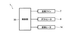
- FIG. 2 is a block diagram showing the configuration of the heating cooker.
- the white arrow drawn in FIG. 1 shows the distribution route and distribution direction of air.
- the heating cooker 1 includes a housing 3, a lid 4, and a container 5 for storing food to be heated, in a main body housing 2 having an outer shape with a curved surface at the bottom.
- a blower duct 6, a blower fan 7, and a duct heater 8 serving as a heating unit are provided.
- the main body housing 2 is configured by a flat surface having an upper surface, and includes a housing portion 3 formed as a recess recessed downward from the upper surface.
- the accommodating portion 3 is a concave portion having a circular shape in plan view with an upper surface opened, and the upper surface is opened and closed by the lid 4.
- the container 5 is accommodated in the accommodating portion 3 through the upper surface opening.
- the main body housing 2 is supported by a pedestal 2a whose outer bottom portion having a curved surface is in contact with the floor surface.
- the housing part 3 is provided with an air outlet 9 and an outlet 10 on its side wall.
- the air outlet 9 opens at the upper part of the side wall of the housing part 3 and blows air laterally toward the inside of the housing part 3.
- the discharge port 10 opens at the lower part of the side wall of the housing part 3 and the air inside the housing part 3 flows out.
- the discharge port 10 is provided in two places.
- An external discharge port 10 ⁇ / b> A that is one of the discharge ports 10 opens to an exhaust duct 13 that communicates with the outside of the main body housing 2.
- a circulation intake port 10B which is the other of the discharge ports 10 opens to the air duct 6 so as to return to the upstream side in the air flow direction of the air blowing fan 7 of the air blowing duct 6 which will be described later.
- some air inside the accommodating part 3 circulates through the circulation inlet 10B.
- the container 5 has a circular pan shape in plan view with an upper surface opened.
- the container 5 is accommodated inside the accommodating portion 3 and is fixed to the inner bottom surface of the accommodating portion 3.
- the container 5 contains a food that is an object to be heated.
- the container 5 includes a substantially annular flange portion 5a at the upper edge of the opening.
- the container 5 is provided with the window part 5b in the side wall.
- the window part 5b opens in the location corresponding to the blower outlet 9 of the upper part of the side wall. Thereby, the air blown off in the lateral direction from the blower outlet 9 toward the inside of the housing portion 3 flows into the container 5 through the window portion 5b.
- the tray 11 can be placed inside the container 5.
- the tray 11 includes a plurality of through-holes 11 a for allowing air to easily flow between the upper side and the lower side of the tray 11.
- the air duct 6 is provided inside the main body housing 2 and outside the housing part 3.
- the air duct 6 includes an air inlet 12 for taking in air from the outside of the main body housing 2.
- the air duct 6 communicates the air inlet 12 and the circulating air inlet 10 ⁇ / b> B of the outlet 10 with the air outlet 9.
- a blower fan 7 is disposed in the blower duct 6.
- the blower fan 7 is made of, for example, a sirocco fan and includes an impeller 7b driven by a fan motor 7a.
- the impeller 7b is disposed inside the air duct 6 with an unillustrated air intake portion facing the air inlet 12 and the circulation air inlet 10B side of the exhaust port 10.
- the blower fan 7 When the impeller 7b is rotated by the fan motor 7a, the airflow flows through the blower duct 6. That is, the blower fan 7 circulates the air flowing into the air duct 6 from the air inlet 12 and the circulation air inlet 10 ⁇ / b> B toward the air outlet 9 inside the air duct 6.
- the blower fan 7 is a sirocco fan, but it may be a propeller fan or a turbofan fan.
- the duct heater 8 is disposed inside the air duct 6 on the downstream side in the air flow direction with respect to the blower fan 7 and on the upstream side in the air flow direction with respect to the air outlet 9.
- the duct heater 8 is configured as, for example, a coil for heating the air flowing through the blower duct 6. Note that the heating method of the duct heater 8 is not limited to the coil, and the air flowing through the air duct 6 may be heated by other methods.
- the heating cooker 1 includes a bottom heater 14 at the bottom of the housing 3.
- the bottom heater 14 is disposed between the inner bottom surface of the accommodating portion 3 and the outer bottom surface of the container 5, and transfers heat to the food by directly heating the bottom portion of the container 5.
- the heating cooker 1 equips the main body housing
- the control unit 30 includes a calculation unit, a storage unit, and other electronic components (not shown), and controls the blower fan 7, the duct heater 8, and the bottom heater 14 on the basis of programs and data stored and input in the storage unit and the like. Realize cooking.
- the blower fan 7, the duct heater 8, and the bottom heater 14 are driven.
- airflow flows through the air duct 6 from the air inlet 12 and the circulation air inlet 10 ⁇ / b> B toward the air outlet 9.
- the air inside the air duct 6 is heated to 40 to 230 ° C. by the duct heater 8, for example.
- the air heated by the duct heater 8 is blown out in the lateral direction from the blowout port 9 toward the inside of the housing portion 3.
- the air blown out from the air outlet 9 flows through the window 5b and into the container 5 to heat the food that is to be heated.
- the food can also be heated by the bottom heater 14 through the bottom of the container 5.
- the air that has flowed into the container 5 from the outlet 9 is sent out from the location of the flange portion 5 a at the upper edge of the opening of the container 5 to the gap with the accommodating portion 3 outside the container 5.
- the air sent into the gap between the container 5 and the storage unit 3 flows out of the storage unit 3 through the discharge port 10. Part of the air flowing out of the housing 3 through the discharge port 10 is released to the outside of the main body housing 2 through the exhaust duct 13 and part of the air flows through the air duct 6 to heat the food. To be reused.
- the cooking device 1 basically circulates hot air inside the main body housing 2. And the heating cooker 1 performs the intake from the outside and the exhaust to the outside in order to adjust the humidity inside the accommodating part 3, and replaces a part of circulating hot air.
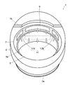
- FIG. 3 is an external perspective view of the heating cooker as viewed from the front upper side
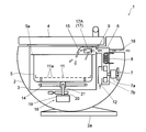
- FIG. 4 is a schematic vertical sectional side view of the heating cooker
- FIG. 5 is a block diagram showing the configuration of the heating cooker. Since the basic configuration of this embodiment is the same as that of the first embodiment described with reference to FIGS. 1 and 2, the same reference numerals are assigned to the same components as those of the first embodiment. The description of the drawings and the description thereof will be omitted. In FIG. 3, drawing of the lid 4 and the tray 11 is omitted.
- the heating cooker 1 includes a housing 3, a lid 4, a container 5, a blower duct 6, a blower fan 7, and a duct heater 8 in a hemispherical main body housing 2.
- the rectifying plate 15 and the rotation drive unit 16 are provided.
- the accommodating part 3 is provided with an air outlet 9 and an outlet 17 on its side wall.
- the air outlet 9 opens at the upper part of the side wall of the housing part 3 and blows air laterally toward the inside of the housing part 3.
- the discharge port 17 is an upper part of the side wall of the accommodating part 3 and opens to both outer sides in the circumferential direction of the air outlet 9 (see FIG. 3), and the air inside the accommodating part 3 flows out.
- the discharge port 17 is provided in two places.
- An external discharge port 17 ⁇ / b> A that is one of the discharge ports 17 opens to an exhaust duct 18 that communicates with the outside of the main body housing 2.
- a circulation intake port 17B which is the other of the discharge ports 17, is open to the air duct 6 so as to return to the upstream side in the air flow direction of the air blowing fan 7 of the air blowing duct 6. Thereby, some air inside the accommodating part 3 circulates via the circulation inlet 17B.
- the container 5 has a circular pan shape in plan view with an upper surface opened, and is configured and arranged in a shape and size in which the upper edge of the opening is lower than the upper edge of the opening of the housing portion 3. And the blower outlet 9 and the discharge port 17 are arrange
- FIG. The window part of the container 5 demonstrated in 1st Embodiment is not provided.
- the rectifying plate 15 is disposed on the inside of the lid 4, that is, on the side of the housing 3 of the lid 4 so as to fit inside the housing 3 when the lid 4 is closed with respect to the housing 3.
- the current plate 15 has a flat plate shape, and is configured to extend from the radially outer side of the container 5 at a location corresponding to the air outlet 9 toward the radially inner side of the container 5.
- the tip portion of the current plate 15 on the radially inner side of the container 5 is bent downward at a predetermined angle.
- positioning location of the baffle plate 15 is not necessarily limited to the inner side of the lid
- the rotation drive unit 16 is disposed at the lower part of the main body housing 2, below the housing unit 3, and at the center in the radial direction of the container 5.
- the rotation drive unit 16 includes a motor 19 and a speed reducer (not shown). Note that the speed reducer is not an essential component of the rotation drive unit 16 and may be omitted.
- the rotating shaft 20 from which the power from the motor 19 is obtained extends upward substantially perpendicularly at the radial center of the container 5. By driving the motor 19, the rotation driving unit 16 can rotate the container 5 around the rotation axis 20 in a horizontal plane.
- the rotation drive unit 16 functions as a stirring unit that rotates the container 5 itself to stir the food.
- the stirring unit may be configured as a stirring blade that rotates separately from the container 5 to stir the food.
- a coupling 21 is provided at a location in the radial center of the outer bottom surface of the container 5 and corresponding to the upper end of the rotating shaft 20.
- the coupling 21 makes the connection between the container 5 and the rotary shaft 20 detachable. Thereby, the container 5 can be removed from the housing portion 3 and taken out of the main body housing 2.
- the control unit 30 shown in FIG. 5 includes a calculation unit, a storage unit, and other electronic components. Based on the program and data stored and input in the storage unit and the like, the blower fan 7, the duct heater 8, the bottom heater 14, and the rotation drive unit. 16 is controlled to realize a series of heat cooking.
- the blower fan 7, the duct heater 8, the bottom heater 14, and the rotation driving unit 16 are driven.
- airflow flows through the air duct 6 from the air inlet 12 and the circulation air inlet 17 ⁇ / b> B toward the air outlet 9.
- the air inside the air duct 6 is heated to 40 to 230 ° C. by the duct heater 8, for example.
- the air heated by the duct heater 8 is blown out in the lateral direction toward the inside of the accommodating portion 3 from the blowout port 9 disposed above the upper end of the container 5.
- the air blown out from the blowout port 9 passes through the upper end of the container 5 from the blowout port 9, hits the rectifying plate 15, and is guided downward inside the container 5.
- the air guided downward inside the container 5 by the current plate 15 circulates inside the container 5 and heats the food that is to be heated.
- the food can also be heated by the bottom heater 14 through the bottom of the container 5.
- the container 5 rotates in a horizontal plane. Thereby, the heating cooker 1 stirs, heating a foodstuff.
- Part of the air that flows out of the housing 3 through the discharge port 17 is discharged to the outside of the main body housing 2 through the exhaust duct 18, and part of the air flows through the air duct 6 to heat the food. To be reused.
- FIG. 6 is an external front view of the cooking device
- FIG. 7 is a schematic vertical sectional side view of the cooking device. Since the basic configuration of this embodiment is the same as that of the first and second embodiments described above, the same components as those of the above embodiments are denoted by the same reference numerals as those in the previous embodiment and described in the drawings. And the description thereof will be omitted. In FIG. 6, the drawing of the lid 4 and the tray 11 is omitted.
- the heating cooker 1 of the third embodiment is supported by the base 2a so that the hemispherical main body housing 2 is inclined with respect to the horizontal plane as shown in FIGS.
- the main body housing 2 is inclined at a predetermined angle so that the back side (the right side in FIG. 7) is lifted and the upper surface is slightly directed to the front side. That is, in the cooking device 1, the inner bottom surface of the container 5 is inclined with respect to the horizontal.
- the cooking device 1 includes a container 5 for storing food that is an object to be heated with an upper surface opened, a container 3 for the container 5 whose upper surface is opened and closed by the lid 4, and a side wall of the container 3.
- a blowout port 9 that blows air laterally toward the inside of the housing part 3 provided in the upper part, discharge ports 10 and 17 through which air inside the storage part 3 provided in the storage part 3 flows out,
- the blower duct 6 which makes 17 and the blower outlet 9 communicate, the blower fan 7 which distribute
- circulates inside the ventilation duct 6 blows off in the horizontal direction toward the inner side of the accommodating part 3 from the upper part of the side wall of the accommodating part 3.
- FIG. Therefore, it is possible to reduce the possibility that heated air for cooking will flow out from the gap between the main body housing 2 and the lid 4. As a result, the heating efficiency is improved.
- the cooking device 1 has the air outlet 9 disposed above the upper end of the container 5. Thereby, it can prevent that the distribution
- the heating cooker 1 is equipped with the baffle plate 15 which guides the air which the blower outlet 9 blows out inside the container 5 below. Thereby, the heated air can be positively sprayed toward the food inside the container 5. Therefore, it is possible to improve heating efficiency.
- the cooking device 1 has the discharge port 17 disposed above the upper end of the container 5.
- the air used for cooking by flowing through the inside of the container 5 can smoothly flow out of the housing portion 3. It is therefore possible to create a suitable flow of air inside the container 5. As a result, the heating efficiency is improved.
- the heating cooker 1 has a rectifying plate 15 disposed inside the lid 4.
- the current plate 15 can be retracted from the upper surface of the container 5 together with the opening of the lid 4. Therefore, the rectifying plate 15 does not interfere with, for example, cleaning the inside of the container 5 or taking out the container 5 from the housing portion 3. That is, in addition to improving the heating efficiency, it is possible to improve operability.
- the cooking device 1 has a container 5 that is detachable from the housing 3.
- the container 5 can be taken out from the storage unit 3. Therefore, in addition to improving heating efficiency, it is possible to improve operability.
- the heating cooker 1 includes a rotation driving unit 16 as an agitation unit for agitating food that is an object to be heated. Thereby, the air heated uniformly with respect to the foodstuff inside the container 5 can be sprayed. Therefore, it is possible to improve heating efficiency.
- the heating cooker 1 includes a rotation driving unit 16 in which the stirring unit rotates the container 5 itself.
- the stirring unit rotates the container 5 itself.
- the food inside the container 5 rotates as a whole. Therefore, it is possible to spray the uniformly heated air on the entire food inside the container 5. As a result, the heating efficiency is further improved.
- the inner bottom surface of the container 5 is inclined with respect to the horizontal. Therefore, the unintentional uneven distribution of the foodstuff inside the container 5 can be prevented effectively. Therefore, it is possible to spray the air heated intensively to the whole food inside the container 5. As a result, the heating efficiency is further improved.
- the heating cooker 1 which can improve a heating efficiency can be provided, suppressing a cost increase.
- the present invention can be used in a heating cooker.
Landscapes
- Engineering & Computer Science (AREA)
- Food Science & Technology (AREA)
- Baking, Grill, Roasting (AREA)
- Cookers (AREA)
- Commercial Cooking Devices (AREA)
Abstract
加熱調理器1は、上面が開口した被加熱物である食品を収容する容器5と、上面が蓋4により開閉される容器5の収容部3と、収容部3の側壁の上部に設けた収容部3の内側に向かって横方向に空気を吹き出す吹出口9と、収容部3に設けた収容部3の内部の空気が流出する排出口10、17と、排出口10、17と吹出口9とを連通させる送風ダクト6と、送風ダクト6の内部に流入する空気を吹出口9に向けて流通させる送風ファン7と、送風ダクト6の内部を流通する空気を加熱する加熱部であるダクトヒータ8と、を備える。
Description
本発明は、被加熱物に対して加熱調理を行う加熱調理器に関する。
従来の加熱調理器が特許文献1に開示されている。この従来の加熱調理器は被加熱物である食品を収容する容器と、この容器を収容する収容部と、容器及び収容部の上面開口に対して開閉する蓋と、加熱した空気を容器の内部に送り込む送風ファン及び加熱部と、を備える。容器は平面視円形の所謂フライパンの形状をなし、内部に内底面に沿って水平面内で回転する食品の撹拌部材を備える。
この加熱調理器は撹拌部材を回転させながら容器の内部に加熱した空気を送り込むことにより、食品に対する加熱調理を実行する。これにより、少量の油で加熱調理を実行することができ、油の節約や加熱時間の短縮、器具の清掃の簡素化、大量の油を使用することに対する危険性の回避を図っている。
しかしながら、特許文献1に記載された従来の加熱調理器は本体に設けた送風ファンから送り出された空気が蓋に設けたダクトの内部を流通し、蓋の内側に設けた吹出口から容器の上面開口を通して下方に向けて吹き出される。ダクトは平面視円形の容器の径方向外側から径方向内側に向かって延びるように蓋の内側に形成されている。すなわち、送風ファンが流通させる空気が本体側から蓋に向かって送り出されることになる。したがって、加熱調理のための加熱された空気が本体と蓋との間の隙間から外部に流出する可能性が高く、加熱効率が低下する虞があるという問題があった。
また、蓋にダクトを設けることにより、蓋の構造が複雑になるとともにダクトを形成するための材料をより多く必要とする。その結果、コストアップや製造工数の増加などの課題があった。さらに、より高い耐熱性がダクトの構造に要求されることで、一層コストアップすることも懸念された。
本発明は上記の点に鑑みなされたものであり、コストアップを抑制しながら加熱効率を向上させることが可能な加熱調理器を提供することを目的とする。
上記の課題を解決するため、本発明の加熱調理器は、上面が開口した被加熱物を収容する容器と、上面が蓋により開閉される前記容器の収容部と、前記収容部の側壁の上部に設けた前記収容部の内側に向かって横方向に空気を吹き出す吹出口と、前記収容部に設けた前記収容部の内部の空気が流出する排出口と、前記排出口と前記吹出口とを連通させる送風ダクトと、前記送風ダクトの内部に流入する空気を前記吹出口に向けて流通させる送風ファンと、前記送風ダクトの内部を流通する空気を加熱する加熱部と、を備えることを特徴としている。
この構成によれば、送風ファンが送風ダクトの内部で流通させる空気が収容部の側壁の上部から収容部の内側に向かって横方向に吹き出される。したがって、加熱調理のための加熱された空気が本体と蓋との間の隙間から外部に流出する可能性が低くなる。さらに、蓋の内側にダクトを設ける必要がない。したがって、そのダクトの形成に係る材料を削減することができ、コストアップや製造工数の増加が抑制される。
また、上記構成の加熱調理器において、前記吹出口を前記容器の上端より上方に配置したことを特徴としている。
また、上記構成の加熱調理器において、前記吹出口が吹き出す空気を前記容器の内部の下方に導く整流板を備えることを特徴としている。
また、上記構成の加熱調理器において、前記排出口を前記容器の上端より上方に配置したことを特徴としている。
また、上記構成の加熱調理器において、前記整流板を前記蓋の内側に配置したことを特徴としている。
また、上記構成の加熱調理器において、前記容器が前記収容部に対して着脱可能であることを特徴としている。
また、上記構成の加熱調理器において、前記被加熱物を撹拌する撹拌部を備えることを特徴としている。
また、上記構成の加熱調理器において、前記撹拌部が前記容器自体を回転させる駆動部からなることを特徴としている。
また、上記構成の加熱調理器において、前記容器の内底面が水平に対して傾斜していることを特徴としている。
本発明の構成によれば、コストアップを抑制しながら加熱効率を向上させることが可能な加熱調理器を提供することができる。
以下、本発明の実施形態を図1~図7に基づき説明する。
<第1実施形態>
最初に、本発明の第1実施形態の加熱調理器について、図1及び図2を用いてその構造と加熱動作とを説明する。図1は加熱調理器の概略垂直断面側面図、図2は加熱調理器の構成を示すブロック図である。なお、図1に描画した白抜き矢印が空気の流通経路及び流通方向を示す。
最初に、本発明の第1実施形態の加熱調理器について、図1及び図2を用いてその構造と加熱動作とを説明する。図1は加熱調理器の概略垂直断面側面図、図2は加熱調理器の構成を示すブロック図である。なお、図1に描画した白抜き矢印が空気の流通経路及び流通方向を示す。
加熱調理器1は、図1に示すように外形が下部に曲面を有する半球状の形態をなす本体筐体2に、収容部3、蓋4、被加熱物である食品を収容する容器5、送風ダクト6、送風ファン7及び加熱部であるダクトヒータ8を備える。
本体筐体2は上面が水平な平面で構成され、この上面から下方に窪んだ凹部として形成された収容部3を備える。収容部3は上面が開口する平面視円形の凹部であって、この上面が蓋4によって開閉される。収容部3にはその上面開口を通して容器5が収容される。本体筐体2は曲面をなす外底部が床面に接する台座2aによって支持される。
収容部3はその側壁に空気の吹出口9と排出口10とを備える。吹出口9は収容部3の側壁の上部に開口し、収容部3の内側に向かって横方向に空気を吹き出す。排出口10は収容部3の側壁の下部に開口し、収容部3の内部の空気が流出する。
排出口10は2箇所に設けられる。排出口10の一方である外部排出口10Aは本体筐体2の外部と連通する排気ダクト13に対して開口している。これにより、収容部3の内部の一部の空気が排気ダクト13を通して本体筐体2の外部に放出される。排出口10の他方である循環吸気口10Bは後述する送風ダクト6の送風ファン7の空気流通方向上流側に戻るように送風ダクト6に対して開口している。これにより、収容部3の内部の一部の空気が循環吸気口10Bを介して循環する。なお、1箇所に設けた排出口10から、本体筐体2の外部に放出する流通経路と、送風ファン7の空気流通方向上流側に戻る流通経路と、に分岐させるようにしても良い。
容器5は上面が開口する平面視円形の鍋状をなす。容器5は収容部3の内部に収容され、収容部3の内底面に固定される。容器5の内部には被加熱物である食品が収容される。容器5はその開口上縁に略環状のフランジ部5aを備える。また、容器5はその側壁に窓部5bを備える。窓部5bはその側壁の上部の吹出口9に対応する箇所に開口する。これにより、吹出口9から収容部3の内側に向かって横方向に吹き出された空気は窓部5bを通って容器5の内部に流通する。
容器5の内部にはトレイ11を置くこともできる。トレイ11はトレイ11の上側と下側との間で容易に空気が流通できるようにするための複数の貫通孔11aを備える。
送風ダクト6は本体筐体2の内部であって、収容部3の外部に設けられる。送風ダクト6は本体筐体2の外部から空気を取り入れる吸気口12を備える。送風ダクト6は吸気口12及び排出口10の循環吸気口10Bと、吹出口9と、を連通させている。送風ダクト6には送風ファン7が配置される。
送風ファン7は例えばシロッコファンからなり、ファンモータ7aにより駆動される羽根車7bを備える。羽根車7bはその不図示の吸気部が吸気口12及び排出口10の循環吸気口10B側に面して送風ダクト6の内部に配置される。ファンモータ7aによって羽根車7bが回転すると、送風ダクト6に気流が流通する。すなわち、送風ファン7は吸気口12及び循環吸気口10Bから送風ダクト6の内部に流入する空気を吹出口9に向けて送風ダクト6の内部で流通させる。なお、本実施形態では送風ファン7をシロッコファンとしたが、プロペラファンやターボファン形式の送風ファンであっても良い。
ダクトヒータ8は送風ダクト6の内部の、送風ファン7に対して空気流通方向下流側であって吹出口9に対して空気流通方向上流側に配置される。ダクトヒータ8は送風ダクト6の内部を流通する空気を加熱するための例えばコイルとして構成される。なお、ダクトヒータ8の加熱方式はコイルに限定されるわけではなく、他の方式で送風ダクト6の内部を流通する空気を加熱しても良い。
また、加熱調理器1は収容部3の底部に底部ヒータ14を備える。底部ヒータ14は収容部3の内底面と容器5の外底面との間に配置され、容器5の底部を直接加熱することにより食品に熱を伝える。
そして、加熱調理器1はその動作制御のために、図2に示すように本体筐体2に制御部30を備える。制御部30は図示しない演算部や記憶部、その他の電子部品で構成され、記憶部等に記憶、入力されたプログラム、データに基づき送風ファン7、ダクトヒータ8及び底部ヒータ14を制御して一連の加熱調理を実現する。
上記構成の加熱調理器1において、不図示の操作部を介して調理の開始が指示されると、送風ファン7、ダクトヒータ8及び底部ヒータ14が駆動される。これにより、吸気口12及び循環吸気口10Bから吹出口9に向けて送風ダクト6の内部に気流が流通する。
送風ダクト6の内部の空気はダクトヒータ8により例えば40~230℃に加熱される。ダクトヒータ8により加熱された空気は吹出口9から収容部3の内部に向かって横方向に吹き出される。吹出口9から吹き出された空気は窓部5bを通って容器5の内部に流通して、被加熱物である食品を加熱する。底部ヒータ14により容器5の底部を介して食品を加熱することもできる。
吹出口9から容器5の内部に流通した空気は容器5の開口上縁のフランジ部5aの箇所から容器5の外側の収容部3との隙間に送り出される。容器5と収容部3との隙間に送り出された空気は排出口10を通って収容部3の外部に流出する。排出口10を通って収容部3の外部に流出する空気は、一部が排気ダクト13を通って本体筐体2の外部に放出され、また一部が送風ダクト6を流通して食品の加熱に再利用される。
ここで、加熱した熱風を全て外部へ排気し、新たに外部から吸気した空気を一から加熱すると加熱効率が非常に悪くなることが懸念される。したがって、加熱料理器1は基本的には本体筐体2の内部で熱風を循環させる。そして、加熱調理器1は収容部3の内部の湿度を調整するために外部からの吸気と、外部への排気とを行い、循環している熱風の一部を入れ換える。
<第2実施形態>
次に、本発明の第2実施形態の加熱調理器について、図3~図5を用いて説明する。図3は加熱調理器の前方上方から見た外観斜視図、図4は加熱調理器の概略垂直断面側面図、図5は加熱調理器の構成を示すブロック図である。なお、この実施形態の基本的な構成は図1及び図2を用いて説明した第1実施形態と同じであるので、第1実施形態と共通する構成要素には前と同じ符号を付し、図面の記載及びその説明を省略するものとする。また、図3では蓋4及びトレイ11の描画を省略している。
次に、本発明の第2実施形態の加熱調理器について、図3~図5を用いて説明する。図3は加熱調理器の前方上方から見た外観斜視図、図4は加熱調理器の概略垂直断面側面図、図5は加熱調理器の構成を示すブロック図である。なお、この実施形態の基本的な構成は図1及び図2を用いて説明した第1実施形態と同じであるので、第1実施形態と共通する構成要素には前と同じ符号を付し、図面の記載及びその説明を省略するものとする。また、図3では蓋4及びトレイ11の描画を省略している。
第2実施形態の加熱調理器1は、図3及び図4に示すように半球状をなす本体筐体2に、収容部3、蓋4、容器5、送風ダクト6、送風ファン7、ダクトヒータ8、整流板15及び回転駆動部16を備える。
収容部3はその側壁に空気の吹出口9と排出口17とを備える。吹出口9は収容部3の側壁の上部に開口し、収容部3の内側に向かって横方向に空気を吹き出す。排出口17は収容部3の側壁の上部であって吹出口9の周方向両外側に開口し(図3参照)、収容部3の内部の空気が流出する。
排出口17は2箇所に設けられる。排出口17の一方である外部排出口17Aは本体筐体2の外部と連通する排気ダクト18に対して開口している。これにより、収容部3の内部の空気が排気ダクト18を通して本体筐体2の外部に放出される。排出口17の他方である循環吸気口17Bは送風ダクト6の送風ファン7の空気流通方向上流側に戻るように送風ダクト6に対して開口している。これにより、収容部3の内部の一部の空気が循環吸気口17Bを介して循環する。なお、1箇所に設けた排出口17から、本体筐体2の外部に放出する流通経路と、送風ファン7の空気流通方向上流側に戻る流通経路と、に分岐させるようにしても良い。
容器5は上面が開口する平面視円形の鍋状をなし、その開口上縁が収容部3の開口上縁より低くなる形状及び大きさで構成され、配置される。そして、吹出口9と排出口17とが容器5の上端より上方に配置される。第1実施形態において説明した容器5の窓部は設けられていない。
整流板15は蓋4の内側、すなわち蓋4を収容部3に対して閉鎖したときに収容部3の内部に収まるよう蓋4の収容部3側に配置される。整流板15は例えば平板状をなし、吹出口9に対応する箇所の容器5の径方向外側から容器5の径方向内側に向かって延びる形で構成される。整流板15の、容器5の径方向内側の先端部分は所定の角度で下方に向かって折り曲げられる。なお、整流板15はその配置箇所が蓋4の内側に限定されるわけではなく、収容部3に配置しても構わない。
回転駆動部16は本体筐体2の下部であって収容部3の下方、容器5の径方向中央部に配置される。回転駆動部16はモータ19と、不図示の減速機とを備える。なお、減速機は回転駆動部16の必須の構成要素ではなく、省略しても良い。モータ19からの動力が得られる回転軸20は容器5の径方向中央で略垂直に上方に向かって延びる。モータ19を駆動することにより、回転駆動部16は回転軸20周りに水平面内で容器5を回転させることができる。
すなわち、回転駆動部16は容器5自体を回転させて食品を撹拌する撹拌部として機能する。撹拌部は、例えば容器5とは別個に回転する撹拌翼として構成して食品を撹拌するようにしても良い。
容器5の外底面の径方向中央であって回転軸20の上端に対応する箇所にはカップリング21が設けられる。カップリング21は容器5と回転軸20との連結を着脱可能にする。これにより、容器5を収容部3から取り外して、本体筐体2の外部に取り出すことができる。
図5に示す制御部30は演算部や記憶部、その他の電子部品で構成され、記憶部等に記憶、入力されたプログラム、データに基づき送風ファン7、ダクトヒータ8、底部ヒータ14及び回転駆動部16を制御して一連の加熱調理を実現する。
上記構成の加熱調理器1において、不図示の操作部を介して調理の開始が指示されると、送風ファン7、ダクトヒータ8、底部ヒータ14及び回転駆動部16が駆動される。これにより、吸気口12及び循環吸気口17Bから吹出口9に向けて送風ダクト6の内部に気流が流通する。
送風ダクト6の内部の空気はダクトヒータ8により例えば40~230℃に加熱される。ダクトヒータ8により加熱された空気は容器5の上端より上方に配置された吹出口9から収容部3の内部に向かって横方向に吹き出される。吹出口9から吹き出された空気は吹出口9から容器5の上端の上方を通って整流板15に当たり、容器5の内部の下方に導かれる。整流板15により容器5の内部の下方に導かれた空気は容器5の内部に流通して、被加熱物である食品を加熱する。底部ヒータ14により容器5の底部を介して食品を加熱することもできる。
回転駆動部16を制御してモータ19が駆動されると、容器5が水平面内で回転する。これにより、加熱調理器1は食品を加熱しながら撹拌する。
吹出口9から容器5の内部に流通した空気は容器5の上端より上方に配置された排出口17から収容部3の外部に流出する。排出口17を通って収容部3の外部に流出する空気は、一部が排気ダクト18を通って本体筐体2の外部に放出され、また一部が送風ダクト6を流通して食品の加熱に再利用される。
<第3実施形態>
次に、本発明の第3実施形態の加熱調理器について、図6及び図7を用いて説明する。図6は加熱調理器の外観正面図、図7は加熱調理器の概略垂直断面側面図である。なお、この実施形態の基本的な構成は先に説明した第1及び第2実施形態と同じであるので、これらの実施形態と共通する構成要素には前と同じ符号を付し、図面の記載及びその説明を省略するものとする。また、図6では蓋4及びトレイ11の描画を省略している。
次に、本発明の第3実施形態の加熱調理器について、図6及び図7を用いて説明する。図6は加熱調理器の外観正面図、図7は加熱調理器の概略垂直断面側面図である。なお、この実施形態の基本的な構成は先に説明した第1及び第2実施形態と同じであるので、これらの実施形態と共通する構成要素には前と同じ符号を付し、図面の記載及びその説明を省略するものとする。また、図6では蓋4及びトレイ11の描画を省略している。
第3実施形態の加熱調理器1は、図6及び図7に示すように半球状をなす本体筐体2が水平面に対して傾斜するように台座2aによって支持される。本体筐体2は背面側(図7における右側)が持ち上げられ、上面がやや正面側を向くように所定の角度で傾斜している。すなわち、加熱調理器1は容器5の内底面が水平に対して傾斜している。
このようにして、加熱調理器1は、上面が開口した被加熱物である食品を収容する容器5と、上面が蓋4により開閉される容器5の収容部3と、収容部3の側壁の上部に設けた収容部3の内側に向かって横方向に空気を吹き出す吹出口9と、収容部3に設けた収容部3の内部の空気が流出する排出口10、17と、排出口10、17と吹出口9とを連通させる送風ダクト6と、送風ダクト6の内部に流入する空気を吹出口9に向けて流通させる送風ファン7と、送風ダクト6の内部を流通する空気を加熱する加熱部であるダクトヒータ8と、を備える。これにより、送風ファン7が送風ダクト6の内部で流通させる空気が収容部3の側壁の上部から収容部3の内側に向かって横方向に吹き出される。したがって、加熱調理のための加熱された空気が本体筐体2と蓋4との間の隙間から外部に流出する可能性を低くすることができる。その結果、加熱効率が向上する。さらに、蓋4の内側にダクトを設ける必要がない。したがって、そのダクトの形成に係る材料を削減することができ、コストアップや製造工数の増加を抑制することが可能である。
また、加熱調理器1は吹出口9を容器5の上端より上方に配置している。これにより、吹出口9から吹き出される空気の流通が容器5によって妨げられることを防止することができる。したがって、加熱調理に用いる加熱された空気を損失することなく容器5の内部に送り込むことができる。その結果、加熱効率が向上する。
そして、加熱調理器1は吹出口9が吹き出す空気を容器5の内部の下方に導く整流板15を備える。これにより、加熱された空気を容器5の内部の食品に向けて積極的に吹き当てることができる。したがって、加熱効率を向上させることが可能である。
また、加熱調理器1は排出口17を容器5の上端より上方に配置している。これにより、容器5の内部を流通させて加熱調理に利用した空気をスムーズに収容部3の外部に流出させることができる。したがって、容器5の内部において空気の好適な流れを生み出すことが可能である。その結果、加熱効率が向上する。
また、加熱調理器1は整流板15を蓋4の内側に配置している。これにより、整流板15を蓋4の開放とともに容器5の上面から退避させることができる。したがって、整流板15が例えば容器5の内部の清掃や容器5の収容部3からの取り出しの邪魔にならない。すなわち、加熱効率の向上に加えて、操作性を向上させることが可能である。
さらに、加熱調理器1は容器5が収容部3に対して着脱可能である。これにより、例えば容器5の内部を清掃するときや、加熱料理後に容器5の内部から食品を取り出すときに、容器5を収容部3から取り出すことができる。したがって、加熱効率の向上に加えて、操作性を向上させることが可能である。
また、加熱調理器1は被加熱物である食品を撹拌する撹拌部として回転駆動部16を備える。これにより、容器5の内部の食品に対して均一に加熱された空気を吹き当てることができる。したがって、加熱効率を向上させることが可能である。
さらに、加熱調理器1は撹拌部が容器5自体を回転させる回転駆動部16からなる。これにより、容器5の内部の食品が全体的に回転する。したがって、容器5の内部の食品全体に均一に加熱された空気を吹き当てることが可能である。その結果、加熱効率が一層向上する。
また、加熱調理器1は容器5の内底面が水平に対して傾斜している。これにより、容器5の内部における食品の意図せぬ偏在を効果的に防止することができる。したがって、容器5の内部の食品全体に集中的に加熱された空気を吹き当てることが可能である。その結果、加熱効率が一層向上する。
そして、本発明の上記実施形態の構成によれば、コストアップを抑制しながら加熱効率を向上させることが可能な加熱調理器1を提供することができる。
以上、本発明の実施形態につき説明したが、本発明の範囲はこれに限定されるものではなく、発明の主旨を逸脱しない範囲で種々の変更を加えて実施することができる。
本発明は、加熱調理器において利用することができる。
1 加熱調理器
2 本体筐体
3 収容部
4 蓋
5 容器
6 送風ダクト
7 送風ファン
8 ダクトヒータ(加熱部)
9 吹出口
10、17 排出口
10A、17A 外部排出口
10B、17B 循環吸気口(排出口)
12 吸気口
13、18 排気ダクト
15 整流板
16 回転駆動部(駆動部、撹拌部)
19 モータ
30 制御部
2 本体筐体
3 収容部
4 蓋
5 容器
6 送風ダクト
7 送風ファン
8 ダクトヒータ(加熱部)
9 吹出口
10、17 排出口
10A、17A 外部排出口
10B、17B 循環吸気口(排出口)
12 吸気口
13、18 排気ダクト
15 整流板
16 回転駆動部(駆動部、撹拌部)
19 モータ
30 制御部
Claims (5)
- 上面が開口した被加熱物を収容する容器と、
上面が蓋により開閉される前記容器の収容部と、
前記収容部の側壁の上部に設けた前記収容部の内側に向かって横方向に空気を吹き出す吹出口と、
前記収容部に設けた前記収容部の内部の空気が流出する排出口と、
前記排出口と前記吹出口とを連通させる送風ダクトと、
前記送風ダクトの内部に流入する空気を前記吹出口に向けて流通させる送風ファンと、
前記送風ダクトの内部を流通する空気を加熱する加熱部と、
を備えることを特徴とする加熱調理器。 - 前記吹出口を前記容器の上端より上方に配置したことを特徴とする請求項1に記載の加熱調理器。
- 前記吹出口が吹き出す空気を前記容器の内部の下方に導く整流板を備えることを特徴とする請求項1または請求項2に記載の加熱調理器。
- 前記排出口を前記容器の上端より上方に配置したことを特徴とする請求項1~請求項3のいずれか1項に記載の加熱調理器。
- 前記被加熱物を撹拌する撹拌部を備えることを特徴とする請求項1~請求項4のいずれか1項に記載の加熱調理器。
Priority Applications (2)
| Application Number | Priority Date | Filing Date | Title |
|---|---|---|---|
| CN201380048800.4A CN104662369B (zh) | 2012-11-30 | 2013-11-29 | 加热烹调器 |
| US14/430,479 US9615694B2 (en) | 2012-11-30 | 2013-11-29 | Heating cooker |
Applications Claiming Priority (2)
| Application Number | Priority Date | Filing Date | Title |
|---|---|---|---|
| JP2012263499A JP6017941B2 (ja) | 2012-11-30 | 2012-11-30 | 加熱調理器 |
| JP2012-263499 | 2012-11-30 |
Publications (1)
| Publication Number | Publication Date |
|---|---|
| WO2014084335A1 true WO2014084335A1 (ja) | 2014-06-05 |
Family
ID=50827963
Family Applications (1)
| Application Number | Title | Priority Date | Filing Date |
|---|---|---|---|
| PCT/JP2013/082143 Ceased WO2014084335A1 (ja) | 2012-11-30 | 2013-11-29 | 加熱調理器 |
Country Status (4)
| Country | Link |
|---|---|
| US (1) | US9615694B2 (ja) |
| JP (1) | JP6017941B2 (ja) |
| CN (1) | CN104662369B (ja) |
| WO (1) | WO2014084335A1 (ja) |
Cited By (3)
| Publication number | Priority date | Publication date | Assignee | Title |
|---|---|---|---|---|
| US20140208605A1 (en) * | 2011-09-16 | 2014-07-31 | Sharp Kabushiki Kaisha | Hair care device |
| CN104274066A (zh) * | 2014-09-18 | 2015-01-14 | 天喜控股集团有限公司 | 一种新型多功能搅拌式烹饪机 |
| KR20180003632U (ko) * | 2018-03-13 | 2018-12-26 | 광동순더디타이롱전기유한공사 | 회전형 조리기 |
Families Citing this family (34)
| Publication number | Priority date | Publication date | Assignee | Title |
|---|---|---|---|---|
| JP6495061B2 (ja) * | 2015-03-19 | 2019-04-03 | 有限会社藤村製作所 | ピザ用窯 |
| CN109310237A (zh) * | 2016-06-14 | 2019-02-05 | 皇家飞利浦有限公司 | 基于空气的炊具 |
| IT201600082900A1 (it) * | 2016-08-05 | 2018-02-05 | De Longhi Appliances Srl | Apparato autonomo per la cottura di alimenti e relativo metodo |
| IT201600082860A1 (it) | 2016-08-05 | 2018-02-05 | De Longhi Appliances Srl | Apparato autonomo per la cottura di alimenti e relativo metodo |
| IT201600099527A1 (it) * | 2016-10-04 | 2018-04-04 | De Longhi Appliances Srl | Apparato autonomo per la cottura di alimenti e relativo metodo |
| WO2018076166A1 (zh) * | 2016-10-25 | 2018-05-03 | 佛山酷釜电器科技有限公司 | 一种高效能空气炸锅 |
| WO2018076164A1 (zh) * | 2016-10-25 | 2018-05-03 | 佛山酷釜电器科技有限公司 | 一种能避免锅底漏液的空气炸锅 |
| CN106361175A (zh) * | 2016-11-25 | 2017-02-01 | 广东顺德成合电器有限公司 | 一种具有烤箱及炒锅功能的多功能空气炸锅 |
| FR3064169B1 (fr) * | 2017-03-27 | 2019-03-22 | Seb S.A. | Appareil de cuisson par flux chauffant avec moyen de remuage |
| CN109303479B (zh) * | 2017-07-28 | 2024-10-22 | 浙江绍兴苏泊尔生活电器有限公司 | 烹饪器具 |
| DE202018006410U1 (de) | 2017-08-09 | 2020-04-23 | Sharkninja Operating Llc | Kochgerät und Komponenten davon |
| CN110367827B (zh) * | 2018-04-12 | 2024-03-22 | 佛山市顺德区美的电热电器制造有限公司 | 物料清洗装置及烹饪器具 |
| USD914447S1 (en) | 2018-06-19 | 2021-03-30 | Sharkninja Operating Llc | Air diffuser |
| CN108577581A (zh) * | 2018-06-21 | 2018-09-28 | 深圳市明翔电器有限公司 | 一种加热均匀的空气炸锅 |
| USD883014S1 (en) | 2018-08-09 | 2020-05-05 | Sharkninja Operating Llc | Food preparation device |
| USD883015S1 (en) | 2018-08-09 | 2020-05-05 | Sharkninja Operating Llc | Food preparation device and parts thereof |
| USD903413S1 (en) | 2018-08-09 | 2020-12-01 | Sharkninja Operating Llc | Cooking basket |
| USD934027S1 (en) | 2018-08-09 | 2021-10-26 | Sharkninja Operating Llc | Reversible cooking rack |
| CN109008669A (zh) * | 2018-10-16 | 2018-12-18 | 广东万家乐厨房科技有限公司 | 一种扰流装置及空气炸锅系统 |
| CN112869583B (zh) * | 2018-10-23 | 2022-07-29 | 贵阳高新惠诚食品有限公司 | 一种带有搅拌功能的食物烘烤机 |
| EP3682775A1 (en) * | 2019-01-17 | 2020-07-22 | Koninklijke Philips N.V. | A cooking apparatus |
| WO2020176477A1 (en) | 2019-02-25 | 2020-09-03 | Sharkninja Operating Llc | Cooking system with guard |
| US20190254476A1 (en) | 2019-02-25 | 2019-08-22 | Sharkninja Operating Llc | Cooking device and components thereof |
| USD918654S1 (en) | 2019-06-06 | 2021-05-11 | Sharkninja Operating Llc | Grill plate |
| USD982375S1 (en) | 2019-06-06 | 2023-04-04 | Sharkninja Operating Llc | Food preparation device |
| CN111012203B (zh) * | 2019-12-17 | 2025-10-31 | 锐莫(佛山)电器科技有限公司 | 烹饪用多功能器具 |
| CN113133684B (zh) * | 2020-01-17 | 2023-10-24 | 广东美的生活电器制造有限公司 | 空气炸锅 |
| US11647861B2 (en) | 2020-03-30 | 2023-05-16 | Sharkninja Operating Llc | Cooking device and components thereof |
| US12593937B2 (en) * | 2020-07-10 | 2026-04-07 | Hamilton Beach Brands, Inc. | Multi-functional oven with air fryer capability |
| WO2022037645A1 (en) * | 2020-08-19 | 2022-02-24 | Crowe Matthew Alfred | Air fryer |
| USD1057126S1 (en) * | 2022-04-26 | 2025-01-07 | Le Feu By Lauritsen ApS | Fireplace |
| US11882961B1 (en) | 2023-01-18 | 2024-01-30 | Sharkninja Operating Llc | Cover plate for cooking devices |
| EP4565101A1 (en) | 2023-05-05 | 2025-06-11 | SharkNinja Operating LLC | Cooking devices, methods, and components thereof |
| CN118662012A (zh) * | 2024-06-29 | 2024-09-20 | 宁波曼华电器有限公司 | 一种风道系统及具有其的烹饪设备 |
Citations (7)
| Publication number | Priority date | Publication date | Assignee | Title |
|---|---|---|---|---|
| JPH01175644U (ja) * | 1988-05-24 | 1989-12-14 | ||
| JPH0219113A (ja) * | 1988-07-06 | 1990-01-23 | Matsushita Electric Ind Co Ltd | 自動製パン機 |
| JPH04300509A (ja) * | 1991-03-28 | 1992-10-23 | Mitsubishi Electric Corp | 回転調理機 |
| JPH0712335B2 (ja) * | 1987-10-12 | 1995-02-15 | 松下電器産業株式会社 | パン製造機 |
| JP2703991B2 (ja) * | 1989-05-24 | 1998-01-26 | 株式会社東芝 | 自動製パン器 |
| JP2003265324A (ja) * | 2002-03-15 | 2003-09-24 | Matsushita Electric Ind Co Ltd | 製パン機 |
| CA2569972A1 (en) * | 2004-06-08 | 2006-01-05 | Seb S.A. | Air flow cooking device |
Family Cites Families (11)
| Publication number | Priority date | Publication date | Assignee | Title |
|---|---|---|---|---|
| JPH08196432A (ja) * | 1995-01-20 | 1996-08-06 | Funai Techno Syst Kk | 製パン器 |
| JPH08336465A (ja) * | 1995-06-14 | 1996-12-24 | Matsushita Electric Ind Co Ltd | 焼物調理器 |
| US5860355A (en) * | 1997-02-21 | 1999-01-19 | Mk Seiko Co., Ltd. | Automatic bread maker |
| US5934177A (en) * | 1997-04-24 | 1999-08-10 | Mk Seiko Co., Ltd. | Automatic bread maker |
| WO2000003601A1 (en) * | 1998-07-14 | 2000-01-27 | Matsushita Electric Industrial Co., Ltd. | Automatic bread maker |
| US20030140796A1 (en) * | 2002-01-31 | 2003-07-31 | Donglei Wang | Bread maker with hot air circulation means |
| JP3998062B2 (ja) * | 2003-02-19 | 2007-10-24 | 株式会社福盛ドゥ | 自動製パン器およびそれを利用したパンの製造方法 |
| CN2647065Y (zh) * | 2003-08-10 | 2004-10-13 | 郭建刚 | 具有煲饭功能的面包机 |
| CN201150473Y (zh) * | 2008-01-09 | 2008-11-19 | 陈海雅 | 一种带有热风通道的烤箱 |
| CN201469049U (zh) * | 2009-07-10 | 2010-05-19 | 漳州灿坤实业有限公司 | 一种具有通风结构的食物调理机 |
| CN102283592B (zh) * | 2011-07-21 | 2014-02-26 | 美的集团股份有限公司 | 半自动制作花式面包的面包机及其制作方法 |
-
2012
- 2012-11-30 JP JP2012263499A patent/JP6017941B2/ja not_active Expired - Fee Related
-
2013
- 2013-11-29 US US14/430,479 patent/US9615694B2/en not_active Expired - Fee Related
- 2013-11-29 CN CN201380048800.4A patent/CN104662369B/zh not_active Expired - Fee Related
- 2013-11-29 WO PCT/JP2013/082143 patent/WO2014084335A1/ja not_active Ceased
Patent Citations (13)
| Publication number | Priority date | Publication date | Assignee | Title |
|---|---|---|---|---|
| JPH0712335B2 (ja) * | 1987-10-12 | 1995-02-15 | 松下電器産業株式会社 | パン製造機 |
| JPH01175644U (ja) * | 1988-05-24 | 1989-12-14 | ||
| JPH0219113A (ja) * | 1988-07-06 | 1990-01-23 | Matsushita Electric Ind Co Ltd | 自動製パン機 |
| JP2703991B2 (ja) * | 1989-05-24 | 1998-01-26 | 株式会社東芝 | 自動製パン器 |
| JPH04300509A (ja) * | 1991-03-28 | 1992-10-23 | Mitsubishi Electric Corp | 回転調理機 |
| JP2003265324A (ja) * | 2002-03-15 | 2003-09-24 | Matsushita Electric Ind Co Ltd | 製パン機 |
| CA2569972A1 (en) * | 2004-06-08 | 2006-01-05 | Seb S.A. | Air flow cooking device |
| WO2006000700A2 (fr) * | 2004-06-08 | 2006-01-05 | Seb S.A. | Appareil de cuisson a flux d’air |
| EP1768535A2 (fr) * | 2004-06-08 | 2007-04-04 | Seb S.A. | Appareil de cuisson a flux d'air |
| CN1964653A (zh) * | 2004-06-08 | 2007-05-16 | 塞伯股份有限公司 | 气流烹调器具 |
| US20080163764A1 (en) * | 2004-06-08 | 2008-07-10 | Seb S.A. | Air Flow Cooking Device |
| DE202005021835U1 (de) * | 2004-06-08 | 2010-06-17 | Seb S.A. | Luftstrom-Garvorrichtung |
| ATE473666T1 (de) * | 2004-06-08 | 2010-07-15 | Seb Sa | Luftstromkochvorrichtung |
Cited By (5)
| Publication number | Priority date | Publication date | Assignee | Title |
|---|---|---|---|---|
| US20140208605A1 (en) * | 2011-09-16 | 2014-07-31 | Sharp Kabushiki Kaisha | Hair care device |
| US9326578B2 (en) * | 2011-09-16 | 2016-05-03 | Sharp Kabushiki Kaisha | Hair care device |
| CN104274066A (zh) * | 2014-09-18 | 2015-01-14 | 天喜控股集团有限公司 | 一种新型多功能搅拌式烹饪机 |
| KR20180003632U (ko) * | 2018-03-13 | 2018-12-26 | 광동순더디타이롱전기유한공사 | 회전형 조리기 |
| KR200492281Y1 (ko) | 2018-03-13 | 2020-10-07 | 자이글주식회사 | 회전형 조리기 |
Also Published As
| Publication number | Publication date |
|---|---|
| US20150201806A1 (en) | 2015-07-23 |
| JP2014109400A (ja) | 2014-06-12 |
| JP6017941B2 (ja) | 2016-11-02 |
| CN104662369A (zh) | 2015-05-27 |
| CN104662369B (zh) | 2016-09-21 |
| US9615694B2 (en) | 2017-04-11 |
Similar Documents
| Publication | Publication Date | Title |
|---|---|---|
| JP6017941B2 (ja) | 加熱調理器 | |
| WO2021120576A1 (zh) | 烹饪用多功能器具 | |
| CN111372501A (zh) | 用于烹饪食物的自主装置以及烹饪方法 | |
| JP6402367B2 (ja) | マイクロ波加熱装置 | |
| TW201836474A (zh) | 加熱調理器 | |
| CN112656246A (zh) | 烹饪装置 | |
| CN103080654A (zh) | 加热烹调器 | |
| JP2014108205A (ja) | 加熱調理器 | |
| CN208876242U (zh) | 烘焙器具 | |
| CN114246487A (zh) | 烹饪器具 | |
| CN216431824U (zh) | 一种用于微波炉的多功能烹饪组件和微波炉 | |
| JP6131717B2 (ja) | 加熱調理器 | |
| CN212085938U (zh) | 空气炸烹饪器具电机罩及具有该电机罩的空气炸烹饪器具 | |
| CN212089204U (zh) | 盖体及具有其的烹饪器具 | |
| JP2006292181A (ja) | 電子レンジ | |
| JP3942427B2 (ja) | 加熱調理器 | |
| CN222487027U (zh) | 一种风冷烹饪器具 | |
| CN216393852U (zh) | 空气炸锅 | |
| CN207782592U (zh) | 用于料理机马达的散热结构和料理机 | |
| KR100676135B1 (ko) | 이중 컨벡션팬이 구비된 가열조리기 | |
| JP6639289B2 (ja) | 加熱調理器 | |
| CN220757227U (zh) | 一种炸桶结构及空气炸锅 | |
| JP3863539B2 (ja) | 加熱調理器 | |
| JP2006003030A (ja) | 加熱調理器 | |
| JP2000039153A (ja) | 加熱調理器 |
Legal Events
| Date | Code | Title | Description |
|---|---|---|---|
| 121 | Ep: the epo has been informed by wipo that ep was designated in this application |
Ref document number: 13857959 Country of ref document: EP Kind code of ref document: A1 |
|
| WWE | Wipo information: entry into national phase |
Ref document number: 14430479 Country of ref document: US |
|
| NENP | Non-entry into the national phase |
Ref country code: DE |
|
| 122 | Ep: pct application non-entry in european phase |
Ref document number: 13857959 Country of ref document: EP Kind code of ref document: A1 |