WO2014068718A1 - 車両の走行制御装置 - Google Patents
車両の走行制御装置 Download PDFInfo
- Publication number
- WO2014068718A1 WO2014068718A1 PCT/JP2012/078226 JP2012078226W WO2014068718A1 WO 2014068718 A1 WO2014068718 A1 WO 2014068718A1 JP 2012078226 W JP2012078226 W JP 2012078226W WO 2014068718 A1 WO2014068718 A1 WO 2014068718A1
- Authority
- WO
- WIPO (PCT)
- Prior art keywords
- engine
- traveling
- cylinder
- amount
- valve
- Prior art date
Links
Images


Classifications
-
- F—MECHANICAL ENGINEERING; LIGHTING; HEATING; WEAPONS; BLASTING
- F02—COMBUSTION ENGINES; HOT-GAS OR COMBUSTION-PRODUCT ENGINE PLANTS
- F02D—CONTROLLING COMBUSTION ENGINES
- F02D13/00—Controlling the engine output power by varying inlet or exhaust valve operating characteristics, e.g. timing
- F02D13/02—Controlling the engine output power by varying inlet or exhaust valve operating characteristics, e.g. timing during engine operation
- F02D13/06—Cutting-out cylinders
-
- B—PERFORMING OPERATIONS; TRANSPORTING
- B60—VEHICLES IN GENERAL
- B60W—CONJOINT CONTROL OF VEHICLE SUB-UNITS OF DIFFERENT TYPE OR DIFFERENT FUNCTION; CONTROL SYSTEMS SPECIALLY ADAPTED FOR HYBRID VEHICLES; ROAD VEHICLE DRIVE CONTROL SYSTEMS FOR PURPOSES NOT RELATED TO THE CONTROL OF A PARTICULAR SUB-UNIT
- B60W30/00—Purposes of road vehicle drive control systems not related to the control of a particular sub-unit, e.g. of systems using conjoint control of vehicle sub-units, or advanced driver assistance systems for ensuring comfort, stability and safety or drive control systems for propelling or retarding the vehicle
- B60W30/18—Propelling the vehicle
- B60W30/18009—Propelling the vehicle related to particular drive situations
- B60W30/18072—Coasting
-
- B—PERFORMING OPERATIONS; TRANSPORTING
- B60—VEHICLES IN GENERAL
- B60W—CONJOINT CONTROL OF VEHICLE SUB-UNITS OF DIFFERENT TYPE OR DIFFERENT FUNCTION; CONTROL SYSTEMS SPECIALLY ADAPTED FOR HYBRID VEHICLES; ROAD VEHICLE DRIVE CONTROL SYSTEMS FOR PURPOSES NOT RELATED TO THE CONTROL OF A PARTICULAR SUB-UNIT
- B60W10/00—Conjoint control of vehicle sub-units of different type or different function
- B60W10/02—Conjoint control of vehicle sub-units of different type or different function including control of driveline clutches
-
- B—PERFORMING OPERATIONS; TRANSPORTING
- B60—VEHICLES IN GENERAL
- B60W—CONJOINT CONTROL OF VEHICLE SUB-UNITS OF DIFFERENT TYPE OR DIFFERENT FUNCTION; CONTROL SYSTEMS SPECIALLY ADAPTED FOR HYBRID VEHICLES; ROAD VEHICLE DRIVE CONTROL SYSTEMS FOR PURPOSES NOT RELATED TO THE CONTROL OF A PARTICULAR SUB-UNIT
- B60W10/00—Conjoint control of vehicle sub-units of different type or different function
- B60W10/04—Conjoint control of vehicle sub-units of different type or different function including control of propulsion units
- B60W10/06—Conjoint control of vehicle sub-units of different type or different function including control of propulsion units including control of combustion engines
-
- B—PERFORMING OPERATIONS; TRANSPORTING
- B60—VEHICLES IN GENERAL
- B60W—CONJOINT CONTROL OF VEHICLE SUB-UNITS OF DIFFERENT TYPE OR DIFFERENT FUNCTION; CONTROL SYSTEMS SPECIALLY ADAPTED FOR HYBRID VEHICLES; ROAD VEHICLE DRIVE CONTROL SYSTEMS FOR PURPOSES NOT RELATED TO THE CONTROL OF A PARTICULAR SUB-UNIT
- B60W30/00—Purposes of road vehicle drive control systems not related to the control of a particular sub-unit, e.g. of systems using conjoint control of vehicle sub-units, or advanced driver assistance systems for ensuring comfort, stability and safety or drive control systems for propelling or retarding the vehicle
- B60W30/18—Propelling the vehicle
- B60W30/20—Reducing vibrations in the driveline
-
- F—MECHANICAL ENGINEERING; LIGHTING; HEATING; WEAPONS; BLASTING
- F02—COMBUSTION ENGINES; HOT-GAS OR COMBUSTION-PRODUCT ENGINE PLANTS
- F02D—CONTROLLING COMBUSTION ENGINES
- F02D13/00—Controlling the engine output power by varying inlet or exhaust valve operating characteristics, e.g. timing
- F02D13/02—Controlling the engine output power by varying inlet or exhaust valve operating characteristics, e.g. timing during engine operation
- F02D13/0203—Variable control of intake and exhaust valves
- F02D13/0207—Variable control of intake and exhaust valves changing valve lift or valve lift and timing
- F02D13/0211—Variable control of intake and exhaust valves changing valve lift or valve lift and timing the change of valve timing is caused by the change in valve lift, i.e. both valve lift and timing are functionally related
-
- F—MECHANICAL ENGINEERING; LIGHTING; HEATING; WEAPONS; BLASTING
- F02—COMBUSTION ENGINES; HOT-GAS OR COMBUSTION-PRODUCT ENGINE PLANTS
- F02D—CONTROLLING COMBUSTION ENGINES
- F02D13/00—Controlling the engine output power by varying inlet or exhaust valve operating characteristics, e.g. timing
- F02D13/02—Controlling the engine output power by varying inlet or exhaust valve operating characteristics, e.g. timing during engine operation
- F02D13/0203—Variable control of intake and exhaust valves
- F02D13/0215—Variable control of intake and exhaust valves changing the valve timing only
- F02D13/0219—Variable control of intake and exhaust valves changing the valve timing only by shifting the phase, i.e. the opening periods of the valves are constant
-
- F—MECHANICAL ENGINEERING; LIGHTING; HEATING; WEAPONS; BLASTING
- F02—COMBUSTION ENGINES; HOT-GAS OR COMBUSTION-PRODUCT ENGINE PLANTS
- F02D—CONTROLLING COMBUSTION ENGINES
- F02D13/00—Controlling the engine output power by varying inlet or exhaust valve operating characteristics, e.g. timing
- F02D13/02—Controlling the engine output power by varying inlet or exhaust valve operating characteristics, e.g. timing during engine operation
- F02D13/04—Controlling the engine output power by varying inlet or exhaust valve operating characteristics, e.g. timing during engine operation using engine as brake
-
- F—MECHANICAL ENGINEERING; LIGHTING; HEATING; WEAPONS; BLASTING
- F02—COMBUSTION ENGINES; HOT-GAS OR COMBUSTION-PRODUCT ENGINE PLANTS
- F02D—CONTROLLING COMBUSTION ENGINES
- F02D29/00—Controlling engines, such controlling being peculiar to the devices driven thereby, the devices being other than parts or accessories essential to engine operation, e.g. controlling of engines by signals external thereto
- F02D29/02—Controlling engines, such controlling being peculiar to the devices driven thereby, the devices being other than parts or accessories essential to engine operation, e.g. controlling of engines by signals external thereto peculiar to engines driving vehicles; peculiar to engines driving variable pitch propellers
-
- F—MECHANICAL ENGINEERING; LIGHTING; HEATING; WEAPONS; BLASTING
- F02—COMBUSTION ENGINES; HOT-GAS OR COMBUSTION-PRODUCT ENGINE PLANTS
- F02D—CONTROLLING COMBUSTION ENGINES
- F02D41/00—Electrical control of supply of combustible mixture or its constituents
- F02D41/0002—Controlling intake air
-
- F—MECHANICAL ENGINEERING; LIGHTING; HEATING; WEAPONS; BLASTING
- F02—COMBUSTION ENGINES; HOT-GAS OR COMBUSTION-PRODUCT ENGINE PLANTS
- F02D—CONTROLLING COMBUSTION ENGINES
- F02D41/00—Electrical control of supply of combustible mixture or its constituents
- F02D41/0002—Controlling intake air
- F02D41/0005—Controlling intake air during deceleration
-
- F—MECHANICAL ENGINEERING; LIGHTING; HEATING; WEAPONS; BLASTING
- F02—COMBUSTION ENGINES; HOT-GAS OR COMBUSTION-PRODUCT ENGINE PLANTS
- F02D—CONTROLLING COMBUSTION ENGINES
- F02D41/00—Electrical control of supply of combustible mixture or its constituents
- F02D41/02—Circuit arrangements for generating control signals
- F02D41/04—Introducing corrections for particular operating conditions
- F02D41/12—Introducing corrections for particular operating conditions for deceleration
- F02D41/123—Introducing corrections for particular operating conditions for deceleration the fuel injection being cut-off
- F02D41/126—Introducing corrections for particular operating conditions for deceleration the fuel injection being cut-off transitional corrections at the end of the cut-off period
-
- B—PERFORMING OPERATIONS; TRANSPORTING
- B60—VEHICLES IN GENERAL
- B60W—CONJOINT CONTROL OF VEHICLE SUB-UNITS OF DIFFERENT TYPE OR DIFFERENT FUNCTION; CONTROL SYSTEMS SPECIALLY ADAPTED FOR HYBRID VEHICLES; ROAD VEHICLE DRIVE CONTROL SYSTEMS FOR PURPOSES NOT RELATED TO THE CONTROL OF A PARTICULAR SUB-UNIT
- B60W30/00—Purposes of road vehicle drive control systems not related to the control of a particular sub-unit, e.g. of systems using conjoint control of vehicle sub-units, or advanced driver assistance systems for ensuring comfort, stability and safety or drive control systems for propelling or retarding the vehicle
- B60W30/18—Propelling the vehicle
- B60W30/18009—Propelling the vehicle related to particular drive situations
- B60W30/18072—Coasting
- B60W2030/18081—With torque flow from driveshaft to engine, i.e. engine being driven by vehicle
-
- B—PERFORMING OPERATIONS; TRANSPORTING
- B60—VEHICLES IN GENERAL
- B60W—CONJOINT CONTROL OF VEHICLE SUB-UNITS OF DIFFERENT TYPE OR DIFFERENT FUNCTION; CONTROL SYSTEMS SPECIALLY ADAPTED FOR HYBRID VEHICLES; ROAD VEHICLE DRIVE CONTROL SYSTEMS FOR PURPOSES NOT RELATED TO THE CONTROL OF A PARTICULAR SUB-UNIT
- B60W30/00—Purposes of road vehicle drive control systems not related to the control of a particular sub-unit, e.g. of systems using conjoint control of vehicle sub-units, or advanced driver assistance systems for ensuring comfort, stability and safety or drive control systems for propelling or retarding the vehicle
- B60W30/18—Propelling the vehicle
- B60W30/18009—Propelling the vehicle related to particular drive situations
- B60W30/18072—Coasting
- B60W2030/1809—Without torque flow between driveshaft and engine, e.g. with clutch disengaged or transmission in neutral
-
- B—PERFORMING OPERATIONS; TRANSPORTING
- B60—VEHICLES IN GENERAL
- B60W—CONJOINT CONTROL OF VEHICLE SUB-UNITS OF DIFFERENT TYPE OR DIFFERENT FUNCTION; CONTROL SYSTEMS SPECIALLY ADAPTED FOR HYBRID VEHICLES; ROAD VEHICLE DRIVE CONTROL SYSTEMS FOR PURPOSES NOT RELATED TO THE CONTROL OF A PARTICULAR SUB-UNIT
- B60W30/00—Purposes of road vehicle drive control systems not related to the control of a particular sub-unit, e.g. of systems using conjoint control of vehicle sub-units, or advanced driver assistance systems for ensuring comfort, stability and safety or drive control systems for propelling or retarding the vehicle
- B60W30/18—Propelling the vehicle
- B60W30/20—Reducing vibrations in the driveline
- B60W2030/206—Reducing vibrations in the driveline related or induced by the engine
-
- F—MECHANICAL ENGINEERING; LIGHTING; HEATING; WEAPONS; BLASTING
- F02—COMBUSTION ENGINES; HOT-GAS OR COMBUSTION-PRODUCT ENGINE PLANTS
- F02D—CONTROLLING COMBUSTION ENGINES
- F02D13/00—Controlling the engine output power by varying inlet or exhaust valve operating characteristics, e.g. timing
- F02D13/02—Controlling the engine output power by varying inlet or exhaust valve operating characteristics, e.g. timing during engine operation
- F02D13/0261—Controlling the valve overlap
-
- F—MECHANICAL ENGINEERING; LIGHTING; HEATING; WEAPONS; BLASTING
- F02—COMBUSTION ENGINES; HOT-GAS OR COMBUSTION-PRODUCT ENGINE PLANTS
- F02D—CONTROLLING COMBUSTION ENGINES
- F02D13/00—Controlling the engine output power by varying inlet or exhaust valve operating characteristics, e.g. timing
- F02D13/02—Controlling the engine output power by varying inlet or exhaust valve operating characteristics, e.g. timing during engine operation
- F02D13/0269—Controlling the valves to perform a Miller-Atkinson cycle
-
- F—MECHANICAL ENGINEERING; LIGHTING; HEATING; WEAPONS; BLASTING
- F02—COMBUSTION ENGINES; HOT-GAS OR COMBUSTION-PRODUCT ENGINE PLANTS
- F02D—CONTROLLING COMBUSTION ENGINES
- F02D41/00—Electrical control of supply of combustible mixture or its constituents
- F02D41/0002—Controlling intake air
- F02D2041/001—Controlling intake air for engines with variable valve actuation
-
- Y—GENERAL TAGGING OF NEW TECHNOLOGICAL DEVELOPMENTS; GENERAL TAGGING OF CROSS-SECTIONAL TECHNOLOGIES SPANNING OVER SEVERAL SECTIONS OF THE IPC; TECHNICAL SUBJECTS COVERED BY FORMER USPC CROSS-REFERENCE ART COLLECTIONS [XRACs] AND DIGESTS
- Y02—TECHNOLOGIES OR APPLICATIONS FOR MITIGATION OR ADAPTATION AGAINST CLIMATE CHANGE
- Y02T—CLIMATE CHANGE MITIGATION TECHNOLOGIES RELATED TO TRANSPORTATION
- Y02T10/00—Road transport of goods or passengers
- Y02T10/10—Internal combustion engine [ICE] based vehicles
- Y02T10/12—Improving ICE efficiencies
-
- Y—GENERAL TAGGING OF NEW TECHNOLOGICAL DEVELOPMENTS; GENERAL TAGGING OF CROSS-SECTIONAL TECHNOLOGIES SPANNING OVER SEVERAL SECTIONS OF THE IPC; TECHNICAL SUBJECTS COVERED BY FORMER USPC CROSS-REFERENCE ART COLLECTIONS [XRACs] AND DIGESTS
- Y02—TECHNOLOGIES OR APPLICATIONS FOR MITIGATION OR ADAPTATION AGAINST CLIMATE CHANGE
- Y02T—CLIMATE CHANGE MITIGATION TECHNOLOGIES RELATED TO TRANSPORTATION
- Y02T10/00—Road transport of goods or passengers
- Y02T10/10—Internal combustion engine [ICE] based vehicles
- Y02T10/40—Engine management systems
Definitions
- the present invention relates to a vehicle travel control device, and more particularly to re-acceleration improvement and shock suppression when returning from inertial travel to normal travel.
- Inertia running is considered in which the engine braking force is reduced rather than engine braking.
- the device described in Patent Document 1 is an example. For example, by performing neutral inertia traveling in a state where the power transmission path between the engine and the wheel is cut off, the engine brake is eliminated, and the traveling distance is extended to improve the fuel consumption. A control device that contributes to is described. Although not described in Patent Document 1, as another method for reducing the engine braking force and extending the travel distance to contribute to the improvement of fuel consumption, the power transmission path between the engine and the wheels remains connected.
- cylinder idle inertia running in which at least some of the cylinders of the engine are deactivated is known.
- the pumping loss that occurs when the piston is driven to rotate is reduced and the engine braking force is reduced.
- Patent Document 1 it is described that if a return condition is satisfied during neutral inertia traveling, the vehicle returns to normal traveling.
- the engine rotational speed is increased
- the clutch is connected when the difference in rotational speed between the front and rear of the clutch provided in the power transmission path between the two becomes smaller.
- the neutral inertia traveling the power transmission path between the engine and the wheel is disconnected, so that a rotational speed difference is generated between the rotating elements of the clutch that intermittently connects the engine and the wheel. Therefore, when re-acceleration is performed after returning from neutral inertia running to normal running, it is restored to normal running by increasing the engine speed and reducing the clutch speed difference.
- the present invention has been made against the background of the above circumstances, and the object of the present invention is a vehicle capable of performing neutral inertia traveling and cylinder deactivation inertia traveling, and from these inertia traveling to normal traveling. It is an object of the present invention to provide a vehicle travel control device that can achieve both reacceleration performance and suppression of shock that occurs at the time of recovery.
- the gist of the first invention includes (a) an engine having a plurality of cylinders, a clutch for intermittently connecting a power transmission path between the engine and wheels, and the engine.
- a variable mechanism that varies the amount of intake air sucked into the cylinder, and (b) normal traveling that travels by transmitting the driving force of the engine to the wheels, and (c) the engine and the wheels Neutral inertia traveling that cuts off the power transmission path between, and (d) in a state where the power transmission path between the engine and the wheel is connected, at least some cylinders of the engine are deactivated
- the traveling control device for a vehicle that performs the cylinder deactivation inertia traveling (e) when returning from the neutral inertia traveling to the normal traveling as compared with returning from the cylinder deactivation inertia traveling to the normal traveling.
- the gist of the second invention is the travel control device for a vehicle according to the first invention, wherein the variable mechanism is at least one of valve opening timing, lift amount, and working angle of the intake valve of the engine. It is a variable valve mechanism that changes one. It is also conceivable to control the throttle opening of the engine at the time of return in order to increase the engine rotation speed early or to suppress a shock at the time of return to normal running. For example, when returning from neutral inertia running, it is conceivable that the throttle valve is opened more than when returning from cylinder idle inertia running.
- the shock at the time of return may not be suppressed even if the throttle opening is reduced.
- the amount of fresh air drawn from the throttle valve to the cylinder can be changed, so it is possible to achieve both re-acceleration at return and shock suppression more accurately. it can.
- the gist of the third invention is the vehicle running control apparatus according to the first invention, wherein the neutral inertia running is such that the engine is idling or the fuel supply to the engine is stopped. It is characterized by being. In this way, fuel consumption is reduced, and fuel efficiency is improved.
- FIG. 1 It is the schematic block diagram which showed the principal part of the control system together with the skeleton of the vehicle drive device to which this invention is applied suitably. It is a figure which shows the opening / closing timing of the intake valve at the time of normal driving
- FIG. 7 It is a figure explaining three driving modes performed by the vehicle drive device of FIG. 7 is a flowchart for explaining a control operation capable of achieving both re-acceleration at the time of return and shock suppression when returning to normal running during inertial running. It is a time chart explaining the operation state by the control action of an electronic control unit.
- FIG. 10 is another flowchart for explaining a control operation that can achieve both reacceleration and shock suppression when returning to normal traveling during inertial traveling.
- FIG. It is another time chart explaining the operation state by control operation of an electronic control unit.
- the valve lift amount of the intake valve corresponds to the amount of movement of the valve in the vertical direction. As the valve lift amount increases, the intake air amount sucked into the engine cylinder increases.
- the operating angle of the intake valve corresponds to the rotation angle of the crankshaft from when the intake valve is opened to when it is closed.
- the engine brake traveling basically means traveling with the fuel supply to the engine stopped and the power transmission path between the engine and the wheels connected.
- engine braking force is generated by rotational resistance such as pumping loss and friction torque due to driven rotation of the engine.
- engine braking force is generated when the engine is driven to rotate, such as at high vehicle speeds. Therefore, such a traveling state is also included in the engine brake traveling.
- FIG. 1 is a schematic configuration diagram showing a main part of a control system together with a skeleton diagram of a vehicle drive device 10 constituting a vehicle to which the present invention is preferably applied.
- the vehicle drive device 10 includes an engine 12 that is an internal combustion engine such as a gasoline engine or a diesel engine having a plurality of cylinders 11 that generates power by burning fuel, and the output of the engine 12 is automatic. It is transmitted from the transmission 16 to the left and right wheels 20 via the differential gear unit 18.
- a power transmission device such as a damper device or a torque converter is provided between the engine 12 and the automatic transmission 16, but a motor generator that functions as a driving force source may be provided.
- the engine 12 is inhaled into the cylinder by adjusting various devices necessary for output control of the engine 12, such as the electronic throttle valve 22 and the fuel injection device 24, the opening / closing timing of the intake valve 26, the lift amount, and the operating angle.
- the variable valve mechanism 30 that makes the intake air amount (air mixture amount) variable, some or all of the intake valves 26 and exhaust valves 28 of the cylinders (hereinafter, when these valves 26 and 28 are not particularly distinguished) , Simply referred to as an intake / exhaust valve).
- an intake / exhaust valve In FIG. 1, only one cylinder 11 is shown, but in actuality, a plurality of cylinders 11 (for example, 8) are provided.
- the variable valve mechanism 30 corresponds to the variable mechanism of the present invention.
- the electronic throttle valve 22 controls the intake air amount, and its open / closed state is adjusted. Basically, the control is performed according to the accelerator opening degree Acc, which is the operation amount of the accelerator pedal 36 corresponding to the driver's required output amount.
- the accelerator opening Acc is detected by an accelerator opening sensor 38.
- the fuel injection device 24 injects fuel into the intake port, and can electrically control the injection amount in accordance with the running state. For example, the fuel injection device 24 can stop the fuel supply (fuel cut F / C) even when the vehicle is running, such as when the accelerator opening degree Acc is zero and the accelerator is OFF.
- the cylinder deactivation device 32 can stop a part or all of the intake and exhaust valves of a plurality of cylinders 11 such as 8 cylinders, for example, and all the intake and exhaust valves are stopped in a closed state. As a result, the pumping loss when the engine 12 is driven to rotate in the fuel cut state is reduced, the engine brake is lowered, and the traveling distance of inertial traveling can be extended. Instead of stopping the intake / exhaust valve, the piston may be separated from the crankshaft via a clutch or the like and stopped. Since the cylinder deactivation device 32 is a known technique, its specific structure and operation will be omitted.
- the variable valve mechanism 30 variably controls the opening / closing timing, valve lift amount, and operating angle of the intake valve 26.
- the variable valve mechanism 30 changes the opening / closing timing of the intake valve 26 by, for example, changing the rotation phase of an intake cam (not shown) that defines the opening / closing timing of the intake valve 26 by the intake valve phase actuator 34 shown in FIG. Can be changed.
- 2 to 4 are diagrams showing that the opening / closing timing of the intake valve 26 is adjusted by the variable valve mechanism 30. 2 to 4, the uppermost position corresponds to the piston top dead center (TDC), and the lowermost position corresponds to the piston bottom dead center (BDC).
- FIG. 2 shows the state of the intake valve 26 during normal operation.
- the intake valve 26 is opened immediately before the piston reaches the top dead center, and the intake valve 26 is closed when the piston passes through the bottom dead center by a predetermined angle. ing.
- FIG. 3 shows a state in which the intake valve 26 is changed to the retard side by a predetermined angle by the variable valve mechanism 30.
- the opening timing of the intake valve 26 is delayed from that during normal operation, and the piston is moved upward.
- the intake valve 26 is opened after passing through the dead point.
- the closing timing of the intake valve 26 is also delayed by a predetermined angle from that during normal operation.
- the opening timing of the intake valve 26 is delayed, so that the intake amount of the intake air into the cylinder is reduced.
- FIG. 4 shows a state in which the intake valve 26 is changed to the advance side by a predetermined angle by the variable valve mechanism 30.
- the valve opening timing of the intake valve 26 is advanced earlier than during normal operation.
- the closing timing of the intake valve 26 is also advanced by a predetermined angle from that during normal operation.
- the opening timing of the intake valve 26 is advanced, so that the intake amount of the intake air in the cylinder increases.
- variable valve mechanism 30 changes the initial position of a swing arm (not shown) having a cam surface for swinging the intake valve 26 by, for example, a lift actuator 42 shown in FIG.
- the lift amount of the intake valve 26 can be changed.
- the variable valve mechanism 30 can change the operating angle of the intake valve 26 by changing the use range of the cam surface.
- FIG. 5 shows the relationship between the crank angle of the crankshaft of the engine 12 and the valve lift amount of the intake / exhaust valve.
- the horizontal axis indicates the crank angle
- the vertical axis indicates the valve lift amount of the intake and exhaust valves, and indicates that the valve is closed when the valve lift amount becomes zero.
- the air-fuel mixture is drawn into the cylinder by opening the intake valve 26 immediately before the exhaust valve 28 is closed.
- the solid line indicates the lift amount of the intake valve 26 during normal operation
- the broken line indicates a state where the valve lift amount of the intake valve 26 is smaller than that during normal operation (small lift state)
- the alternate long and short dash line is normal.
- variable valve mechanism 30 can change the amount of valve lift of the intake valve 26.
- the valve lift amount of the intake valve 26 is increased, the intake amount of intake air into the cylinder is increased.
- the valve lift amount of the intake valve 26 is decreased, the intake amount of intake air into the cylinder is decreased.
- FIG. 6 also shows the relationship between the crank angle of the crankshaft of the engine 12 and the valve lift amount of the intake / exhaust valve, as in FIG.
- the variable valve mechanism 30 can change the operating angle ⁇ of the intake valve 26.
- the intake amount of intake air into the cylinder is increased.
- the operation angle of the intake valve 26 is decreased, the intake amount of intake air into the cylinder is decreased. Further, since the specific structure and operation of the variable valve mechanism 30 are known techniques, the description thereof is omitted.
- the automatic transmission 16 is a planetary gear type stepped gear in which a plurality of gear stages having different gear ratios ⁇ are established depending on the disengagement state of a plurality of hydraulic friction engagement devices (clutch and brake).
- the shift control is performed by an electromagnetic hydraulic control valve, a switching valve, or the like provided in the hydraulic control device 40.
- the clutch C ⁇ b> 1 functions as an input clutch of the automatic transmission 20, and is similarly engaged / released by the hydraulic control device 40.
- the clutch C1 corresponds to an interrupting device that interrupts the power transmission path between the engine 12 and the wheel 20.
- a continuously variable transmission such as a belt type may be used instead of the stepped transmission.
- the clutch C1 corresponds to the clutch of the present invention.
- the vehicle drive device 10 configured as described above includes an electronic control device 50.
- the electronic control unit 50 includes a so-called microcomputer having a CPU, a ROM, a RAM, an input / output interface, and the like, and performs signal processing according to a program stored in advance in the ROM while using a temporary storage function of the RAM. Do.
- the electronic control device 50 may be configured by a plurality of control devices such as a control device for engine control and a control device for automatic transmission control.
- the electronic control unit 50 includes a signal indicating the accelerator opening Acc, which is the operation amount of the accelerator pedal 36, from the accelerator operation amount sensor 38, a signal indicating the throttle opening ⁇ th of the electronic throttle valve 22 from the throttle valve opening sensor 52, an engine A signal representing the rotational speed Ne (engine rotational speed Ne) of the engine 12 from the rotational speed sensor 54, a signal representing the engine water temperature Tw from the engine water temperature sensor 56, a signal representing the occurrence of knocking from the knock sensor 58, and an intake valve phase sensor 60 A signal representing the phase of the intake valve 26, a signal representing the valve lift amount of the intake valve from the intake valve lift sensor 62, and a rotational speed Nin of the input shaft of the automatic transmission 16 from the input shaft rotational speed sensor 64 (input shaft rotational speed Nin). Of the automatic transmission 16 corresponding to the vehicle speed V from the output shaft rotational speed sensor 66. A signal indicating the output shaft rotation speed Nout (output shaft rotation speed Nout) is supplied.
- the electronic control device 50 functionally includes an engine control means 70, a normal traveling means 72, a neutral inertia traveling means 74, a cylinder deactivation inertia traveling means 76, and a traveling state determination means 76.
- the engine control means 70 sequentially determines a target engine operating point at which the target engine output Pe * calculated based on the accelerator opening Acc and the vehicle speed V is obtained on a preset optimum fuel consumption line, and the target engine operating point is The engine speed Ne and the engine torque Te shown are sequentially determined as the target engine speed Ne * and the target engine torque Te *, respectively.
- the engine control means 90 sequentially controls the electronic throttle valve 22 and the fuel injection device 24 so that the target engine torque Te * and the target engine rotational speed Ne * are output from the engine 12.
- the engine control means 70 controls the variable valve mechanism 30 to adjust the opening / closing timing, the valve lift amount, and the operating angle of the intake valve 26 according to the traveling state. For example, when traveling at high speed, the engine control means 70 changes the opening / closing timing of the intake valve 26 to the advance side, the valve lift amount to the increase side (large lift side), and the operating angle to the enlargement side. When the vehicle is traveling at a low speed, the engine control means 70 changes the opening / closing timing of the intake valve 26 to the retard side, the valve lift amount to the decrease side (small lift side), and the operating angle to the decrease side.
- the normal traveling means 72 travels by transmitting the driving force of the engine 12 to the wheels 20. That is, as shown in the correspondence table of the driving modes in FIG. 7, during normal driving, the engine 12 is driven to rotate by being supplied with fuel, and the power transmission path between the engine 12 and the wheels 20 is The intermittent clutch C1 is in an engaged state. Accordingly, the torque of the engine 12 is transmitted to the wheel 20 via the clutch C1 and the like.
- the neutral inertia traveling means 74 performs neutral inertia traveling in a traveling state in which inertial traveling with the accelerator opening Acc being equal to or less than a predetermined value and the vehicle speed V being equal to or greater than a predetermined value can be performed.
- the neutral inertia running as shown in the correspondence table of FIG. 7, the clutch C1 is released and the engine 12 is disconnected from the wheel 20, while the engine 12 is supplied with fuel and operated in an idle operation state (idling state). Run inertia in the state.
- the engine braking force becomes smaller than that of the conventional engine brake traveling, and the engine braking force becomes substantially 0 because the clutch C1 is released, so the traveling resistance is decreased and the traveling distance by inertia traveling is increased.
- Fuel consumption can be improved.
- the fuel consumption is consumed by operating the engine 12 in the idle operation state, but the inertial travel distance is longer than the engine brake travel, so the frequency of re-acceleration is reduced, and the fuel efficiency is improved as a whole.
- the engine 12 is idled during the neutral inertia running, but the fuel supply to the engine 12 may be stopped to stop the rotation of the engine 12. Therefore, the neutral inertia running of the present invention includes not only the idling operation of the engine 12 but also the mode in which the fuel supply to the engine 12 is stopped to stop the rotation of the engine 12.
- the cylinder deactivation inertia traveling means 76 performs cylinder deactivation inertia traveling in a traveling state in which inertial traveling can be performed. As shown in the correspondence table of FIG. 7, in the cylinder deactivation inertia traveling, the fuel supply to the engine 12 is stopped (fuel cut F / C) while the engagement state of the clutch C1 is maintained and the engine 12 and the wheel 20 are connected. In addition, the cylinder deactivation device 32 stops the intake / exhaust valves of a part (for example, half) of the plurality of cylinders at a position where they are closed.
- the crankshaft is driven and rotated in accordance with the vehicle speed V and the gear stage of the automatic transmission 16, but the intake and exhaust valves of some cylinders 11 are stopped in the closed state, so that the crankshaft is synchronized with the crankshaft.
- the loss due to the pumping action prumping loss
- the engine braking force is reduced as compared with engine braking.
- the distance traveled by inertial traveling is increased, and fuel efficiency is improved. Therefore, although the engine braking force is larger than that of the neutral inertia traveling and the travel distance by the inertia traveling is relatively short, the engine 12 is only fuel-cut and driven to rotate. Efficiencies similar to or better than running can be obtained.
- neutral inertia running including engine braking and cylinder idle inertia running are selectively executed.
- This travel mode is appropriately switched by, for example, a preset inertia travel mode map during inertia travel, a travel mode selection switch provided in the driver's seat and switchable by the driver, and the like.
- the traveling state determination means 78 determines whether or not the traveling state of the vehicle is inertial traveling. If the traveling state is inertial traveling, the inertial traveling is traveling in any inertial traveling mode. It is to determine whether or not. Inertia traveling is determined based on, for example, whether the accelerator opening Acc is equal to or less than a predetermined value and the vehicle speed V is equal to or greater than a predetermined value. Further, the traveling mode during inertial traveling can be determined based on, for example, the operating state of the engine 12 and the engaged state of the clutch C1. The determination can also be made by detecting a command signal for the travel mode output from the electronic control unit 50.
- the vehicle when the driver re-acceleration request is output by driving the accelerator pedal 36 or the like while traveling in inertial traveling, the vehicle is returned to normal traveling from inertial traveling.
- the control method differs between neutral inertia running and cylinder deactivation inertia running. For example, when returning from neutral inertia traveling to normal traveling, it is necessary to engage the clutch C1, but since the engine 12 is operating in idle operation, the engine rotational speed Ne is low and the clutch C1 rotates. Large rotational speed difference between elements. Accordingly, the engine rotational speed Ne is increased until the rotational speed difference between the rotating elements of the clutch C1 becomes a predetermined value or less so that the clutch C1 can be engaged.
- the rotational speed difference of the clutch C1 becomes equal to or less than a predetermined value and the clutch C1 is engaged, the normal traveling is resumed.
- the clutch C1 since the clutch C1 is engaged when returning from the cylinder deactivation inertia traveling to the normal traveling, the difference in rotational speed does not occur in the clutch C1. Therefore, it is returned to normal running only by restarting combustion of the engine 12.
- the rotational speed difference before and after the rotational element of the clutch C1 is, for example, the input shaft rotational speed Nin detected by the input shaft rotational speed sensor 64, the output shaft rotational speed Nout detected by the output shaft rotational speed sensor 66, and the automatic shift. It can be calculated based on the gear ratio ⁇ of the machine 16.
- the engine control means 70 switches the control method of the engine 12 according to the traveling mode during inertial traveling when returning from inertial traveling to normal traveling, thereby improving the reacceleration performance at the time of recovery and shock. Both suppression.
- a specific control method by the engine control means 70 will be described.
- the engine control means 70 controls the phase of the intake valve 26 to the advance side by the variable valve mechanism 30 when returning from the neutral inertia running.
- the variable valve mechanism 30 controls the valve lift amount of the intake valve 26 to the increase side (large lift side).
- the operating angle of the intake valve 26 is controlled to the enlargement side by the variable valve mechanism 30. It is sufficient that at least one of these controls is performed, and these may be performed in parallel.
- the air-fuel mixture (intake air) is rapidly drawn into the cylinder of the engine 12 and the amount of air-fuel mixture increases, so that the combustion pressure in the cylinder increases and the engine speed Ne quickly increases. Be raised. Therefore, the rotational speed difference between the rotating elements of the clutch C1 is also quickly reduced, the engagement of the clutch C1 is also accelerated, and the reacceleration at the time of return is improved.
- the advance amount, valve lift amount, and operating angle of the intake valve 26 by the variable valve mechanism 30 when returning to normal running are obtained in advance through experiments or the like.
- the engine speed Ne is set in advance. It is set to a value that increases at the rate of change.
- the advance amount, the valve lift amount, and the operating angle are not necessarily set to constant values, and may be changed according to, for example, the vehicle speed V, the engine rotational speed Ne, the engine water temperature Tw, and the like.
- the engine rotation speed Ne is quickly increased, the combustion pressure in the cylinder of the engine 12 increases and the engine vibration increases.
- the clutch C1 is released while the engine rotational speed Ne is being increased, the vibration is not transmitted to the wheel 20. That is, no shock occurs at the time of return.
- the engine control means 70 controls the phase of the intake valve 26 to the retard side by the variable valve mechanism 30 when returning from the cylinder deactivation inertia traveling.
- the valve lift amount of the intake valve 26 is controlled to the decreasing side (small lift side) by the variable valve mechanism 30.
- the operating angle of the intake valve 26 is controlled to the decreasing side by the variable valve mechanism 30. It is sufficient that at least one of these controls is performed, and these may be performed in parallel.
- the air-fuel mixture (intake air) sucked into the cylinders of the engine 12 immediately after the request for return to normal running is reduced.
- an increase in the combustion pressure at the start of the engine is suppressed, so that engine vibration at the start of the engine is suppressed.
- the retard amount, the valve lift amount, and the operating angle of the intake valve 26 by the variable valve mechanism 30 when returning to normal running are obtained in advance through experiments and the like, for example, the engine speed Ne is set in advance. It is set to a value that increases at the rate of change. This rate of change is set to a value smaller than the rate of change at the time of return from neutral inertia running.
- the retard amount, the valve lift amount, and the operating angle are not necessarily set to constant values, and may be changed according to, for example, the vehicle speed V, the engine rotational speed Ne, the engine water temperature Tw, and the like.
- the clutch C1 is engaged and the engine speed Ne is higher than the idle speed Nidle. Since the speed is maintained, it is possible to quickly return to normal driving and the reacceleration performance is also maintained.
- the air-fuel mixture (intake air) sucked into the cylinder is controlled by the variable valve mechanism 30 so that normal traveling from cylinder deactivation inertia traveling is controlled.
- control is performed by the variable valve mechanism 30 so that the air-fuel mixture sucked into the cylinder is reduced. That is, when returning from neutral inertia traveling to normal traveling, the amount of air-fuel mixture (intake air amount) sucked into the cylinders of the engine 12 is increased as compared to returning from cylinder idle inertia traveling to normal traveling.
- FIG. 8 is a flowchart for explaining a control operation of the electronic control device 50, that is, a control operation capable of achieving both reacceleration at the time of return and shock suppression when returning to normal travel during inertial travel. It is repeatedly executed with a very short cycle time of about several milliseconds to several tens of milliseconds.
- the above flow is premised on a mode in which a command to switch from inertia traveling to normal traveling is output, for example, by depressing the accelerator pedal 36 during inertia traveling.
- step S1 corresponding to the traveling state determination means 78, it is determined whether or not the current traveling state is an inertial traveling state. If step S1 is negative, this routine is terminated. If step S1 is affirmed, it is determined in step S2 corresponding to the traveling state determination means 78 whether or not the inertia traveling is a cylinder deactivation inertia traveling.
- step S3 corresponding to the engine control means 70, the phase of the intake valve 26 of the engine 12 is controlled to the retard side when returning from the cylinder deactivation inertia traveling to the normal traveling. Alternatively, the valve lift amount of the intake valve 26 is controlled to the decrease side (small lift side). By controlling in this way, engine vibration at the time of starting the engine is suppressed and shock is suppressed.
- step S4 corresponding to the traveling state determination means 78 whether the inertia traveling is a neutral inertia traveling. If step S4 is negative, the routine is terminated.
- step S5 corresponding to the engine control means 70, the phase of the intake valve 26 of the engine 12 is controlled to the advance side when returning from neutral inertia traveling to normal traveling. Alternatively, the valve lift amount of the intake valve 26 is controlled to the increase side (large lift side).
- the engine rotational speed Ne is quickly increased to the rotational speed at which the clutch C1 can be engaged, so that the clutch C1 is quickly engaged and the reacceleration at the time of return is improved.
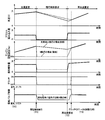
- FIG. 9 is a time chart for explaining the operation state by the control operation of the electronic control unit 50, and specifically shows the operation state when switching is made in the order of acceleration travel, inertia travel, and reacceleration travel.
- the horizontal axis indicates time
- the vertical axis indicates the vehicle speed V
- the accelerator depression amount corresponding to the accelerator opening Acc the engine rotation speed Ne
- the fuel injection amount the engagement state of the clutch C1, and the intake air in order from the top.
- the state of the valve 26 is shown.
- the solid line corresponds to the control during cylinder idle coasting (during cylinder idle coasting), and the broken line corresponds to control during neutral coasting (N coasting).
- the fuel injection amount is controlled according to the accelerator depression amount, and the engine speed Ne and the vehicle speed V are increased. And if depression of the accelerator pedal 36 is cancelled
- the clutch C1 is released during the inertia traveling, and the fuel injection amount is controlled so that the engine rotational speed Ne becomes the idle rotational speed Nidle. Since the clutch C1 is disengaged, the engine rotational speed Ne quickly decreases to the idle rotational speed Nidle. At this time, since the clutch C1 is released, the deceleration force of the vehicle further decreases as compared with the cylinder deactivation inertia traveling as the engine braking force becomes substantially zero. Therefore, as shown by the broken line, the decrease in the vehicle speed V is smoother than the cylinder deactivation inertia traveling shown by the solid line.
- the intake air amount increases compared to the cylinder idle inertia running, so when returning from the neutral inertia running to the normal running.
- the amount of air-fuel mixture sucked into the cylinder (intake air amount) is larger than that in cylinder deactivation inertia traveling. Therefore, the engine rotational speed Ne can be quickly increased as compared with the cylinder deactivation inertia traveling, and the rotational speed difference between the rotating elements of the clutch C1 can be reduced in a short time. Therefore, the clutch C1 is connected early. Thus, it is possible to improve the reacceleration performance when returning to normal running.
- the power transmission path between the engine 12 and the wheels 20 is interrupted, so that the air-fuel mixture sucked into the cylinder increases, so that the combustion pressure in the cylinder is increased. Even if the engine vibration at the time of starting becomes large, it is not transmitted to the wheel 20 and no shock is generated.
- the amount of air-fuel mixture sucked into the cylinder at the time of returning is smaller than that from returning from neutral inertia traveling, so engine vibration accompanying combustion of engine 12 is reduced. It becomes smaller and the shock at the time of return is also suppressed.
- the engine 12 and the wheels 20 are already connected to each other, so that the decrease in the engine rotation speed Ne is small, and the driver desires even if the engine rotation speed Ne does not increase rapidly. Re-acceleration can be obtained. In this way, it is possible to achieve both reacceleration performance when returning from inertia traveling to normal traveling and shock suppression during recovery.
- the throttle opening of the engine 12 at the time of return in order to increase the engine rotational speed Ne at an early stage or to suppress a shock at the time of return to normal running.
- the shock at the time of return is not reduced even if the throttle opening ⁇ th is reduced. It may not be suppressed.
- the variable valve mechanism 30 the amount of fresh air drawn from the electronic throttle valve 22 to the cylinder 11 can be changed, so that the reacceleration at the time of return and the shock suppression are more accurately performed. Both can be achieved.
- the neutral inertia running is for the engine 12 to be idled or to stop the fuel supply to the engine 12, so that the fuel consumption is reduced and the fuel consumption is improved.
- the phase of the intake valve 26 is controlled to the advance side by the variable valve mechanism 30 or the valve lift amount of the intake valve 26 is increased when returning from neutral inertia running to normal running.
- the amount of air-fuel mixture is increased by controlling to the side (large lift side), while the phase of the intake valve 26 is controlled to the retard side or the valve of the intake valve 26 when returning from the cylinder resting inertia traveling to the normal traveling
- the lift amount was controlled to the decreasing side (small lift side).
- variable valve mechanism 30 is controlled to increase the air-fuel mixture amount (intake air amount), and When returning from neutral inertia traveling to normal traveling, the variable valve mechanism 30 may be controlled to significantly increase the amount of air-fuel mixture (intake air amount).
- the engine control means 70 in the present embodiment controls the phase of the intake valve 26 to the advance side with respect to the normal operation by the variable valve mechanism 30 when returning from the cylinder resting inertia running to the normal running.
- the valve lift amount of the intake valve 26 is controlled by the variable valve mechanism 30 to be increased from that during normal operation.
- the engine control means 70 controls the variable valve mechanism 30 to greatly control the phase of the intake valve 26 to the advance side than during the normal running.
- the valve lift amount of the intake valve 26 is largely controlled by the variable valve mechanism 30 to the increase side than during normal operation.
- the advance amount and valve lift amount of the intake valve 26 when returning from neutral inertia travel to normal travel are larger than the advance angle and valve lift amount when returning from cylinder rest inertia travel to normal travel. Is set. Therefore, in the present embodiment, the amount of air-fuel mixture (intake air amount) increases even when returning from cylinder idle inertia running to normal running, but when returning from neutral inertia running to normal running, cylinder pause Compared to inertial running, the air-fuel mixture (intake air volume) is greatly increased.
- the same effect as in the above-described embodiment can be obtained.
- the phase of the intake valve 26 is controlled to the advance side or the valve lift amount of the intake valve 26 is increased by the variable valve mechanism 30. Therefore, the engine rotational speed Ne is raised relatively quickly and quickly returned to normal travel. Note that, in cylinder idle inertia traveling, the combustion pressure does not increase significantly and the engine rotational speed Ne is relatively high, so the amount of change in the engine rotational speed Ne when returning to normal traveling is also compared. Shock is not a problem because it is small.
- variable valve mechanism 30 when returning from neutral inertia traveling to normal traveling, the variable valve mechanism 30 causes the phase of the intake valve 26 to advance more than in the case of cylinder idle inertia traveling, or the valve lift amount of the intake valve 26. Therefore, the air-fuel mixture amount is significantly increased as compared with the case of cylinder idle coasting. As a result, the engine speed Ne increases rapidly, and the clutch C1 can be quickly engaged to return to normal travel. Further, since the clutch C1 is disengaged while the engine rotation speed Ne is increasing, vibrations generated at that time are not transmitted to the wheels 20.
- FIG. 10 is a diagram for explaining the main part of the control operation of the electronic control unit 50 according to the present embodiment, that is, the control operation that can achieve both the reacceleration at the time of return and the suppression of shock when returning to the normal travel during inertial travel. It is a flowchart of.
- step S3 is changed to step S10
- step S5 is changed to step S11.
- S10 and S11 which are different from the above-described embodiment will be described.
- step S10 corresponding to the engine control means 70 is executed.
- the phase of the intake valve 26 is controlled to the advance side when returning from cylinder deactivation inertia traveling to normal traveling.
- the valve lift amount of the intake valve 26 is controlled to increase.
- step S11 corresponding to the engine control means 70 is executed.
- the phase of the intake valve 26 is largely controlled to the advance side when returning from neutral inertia traveling to normal traveling.
- the valve lift amount of the intake valve 26 is greatly controlled to the increase side (large lift side).
- the advance amount and valve lift amount of the intake valve when returning from neutral inertia running to normal running are controlled to be significantly larger than when returning from cylinder resting inertia running to normal running. The
- the amount of air-fuel mixture intake air amount
- the engine speed Ne is quickly increased. Therefore, it is possible to quickly engage the clutch C1 and quickly return to normal traveling, and the reacceleration performance is also improved.
- FIG. 11 is a flowchart for explaining an operation state by the control operation of the electronic control device 50 of the present embodiment.
- the intake valve 26 of the engine 12 is advanced or increased. Controlled on the lift side. As a result, the engine 12 starts relatively quickly. Further, in the case of the return from the neutral inertia running indicated by the broken line, the intake valve 26 of the engine 12 is largely controlled to the advance side as compared with the return from the cylinder deactivation inertia running.
- the intake valve 26 of the engine 12 is greatly controlled to the large lift side as compared with the return from the cylinder deactivation inertia running.
- the amount of air-fuel mixture (intake air amount) sucked into the cylinder of the engine 12 increases significantly, the engine speed Ne quickly rises, and the clutch C1 is quickly engaged at time T3. Accordingly, it is possible to quickly return to normal running and obtain high reacceleration performance. Further, since the clutch C1 is disengaged while the engine rotation speed Ne is increasing, vibrations generated at that time are not transmitted to the wheels 20.
- the amount of air-fuel mixture is increased even when returning from cylinder idle inertia running to normal running, and the amount of air-fuel mixture is controlled to increase significantly when returning from neutral inertia running to normal running. Even in this case, when returning from neutral inertia running to normal running, the amount of air-fuel mixture (intake air amount) sucked into the cylinder is larger than when returning from cylinder idle inertia running to normal running. Therefore, it is possible to obtain substantially the same effect as the above-described embodiment.
- the clutch C1 that interrupts the power transmission path between the engine 12 and the wheels 20 is one of the clutches of the automatic transmission 16 that includes a plurality of clutches and brakes and can be switched to neutral.
- the present invention is not limited to the automatic transmission 16 and is not particularly limited as long as it is a clutch that interrupts the power transmission path between the engine 12 and the wheels 20.
- the clutch is not limited to a hydraulic friction engagement device, and various intermittent devices such as an electromagnetic clutch can be used.
- the engine 12 is idling during the neutral inertia running.
- the engine 12 may be stopped by stopping the fuel supply to the engine 12.
- variable valve mechanism 30 is used as a mechanism for adjusting the intake air amount into the cylinder of the engine 12, but the intake air amount may be adjusted by the electronic throttle valve 22. .
- the variable valve mechanism 30 is preferable in consideration of the response of the engine 12.
- the traveling state is the inertial traveling state when returning from the inertial traveling to the normal traveling, but this step is performed for confirmation. It is not always necessary and may be omitted.
- the intake valve 26 is controlled in advance to the retarded angle or the small lift side during traveling in the cylinder deactivation inertia traveling, but is controlled when the reacceleration request is output. It doesn't matter.
- the engine 12 includes the eight cylinders 11 as an example.
- the number of cylinders is not limited to this and may be changed as appropriate. Further, the number of cylinders stopped during cylinder deactivation inertia traveling is not particularly limited.
- the intake valve 26 and the exhaust valve 28 are both closed during the cylinder deactivation inertia traveling.
- the present invention is not necessarily limited to this.
- the intake valve 26 and the exhaust valve 28 are not limited thereto. It is not limited to a mode in which both valves 26 and 28 are closed, such as opening both valves or stopping one of the valves.
- the intake valve 26 and the exhaust valve 28 are stopped in the closed state during the cylinder resting inertia running, but instead of stopping the intake and exhaust valves, the piston is cranked by a clutch or the like. You may make it stop by separating from an axis
- the engine 12 in the neutral inertia running, is idled or stopped by stopping the fuel supply, but it is not necessarily limited to the idling, but at a rotational speed capable of self-running.
- the rotational speed may be appropriately selected as long as the rotational speed is within a range where the fuel consumption can be reduced.
- the phase of the intake valve 26 is advanced or retarded by the variable valve mechanism 30, and the valve lift amount of the intake valve 26 is increased.
- control is appropriately performed on the decrease side, but it may be maintained in a state during normal operation.
- the amount of air-fuel mixture (intake air amount) sucked into the cylinder is greater than when returning from cylinder idle inertia running to normal running. As long as the amount is increased, there is no particular limitation.
Priority Applications (5)
| Application Number | Priority Date | Filing Date | Title |
|---|---|---|---|
| DE112012007082.8T DE112012007082B4 (de) | 2012-10-31 | 2012-10-31 | Fahrzeugantriebssteuergerät |
| US14/439,408 US9896103B2 (en) | 2012-10-31 | 2012-10-31 | Vehicle drive controller |
| JP2014544133A JP5907280B2 (ja) | 2012-10-31 | 2012-10-31 | 車両の走行制御装置 |
| PCT/JP2012/078226 WO2014068718A1 (ja) | 2012-10-31 | 2012-10-31 | 車両の走行制御装置 |
| CN201280076806.8A CN104755728B (zh) | 2012-10-31 | 2012-10-31 | 车辆的行驶控制装置 |
Applications Claiming Priority (1)
| Application Number | Priority Date | Filing Date | Title |
|---|---|---|---|
| PCT/JP2012/078226 WO2014068718A1 (ja) | 2012-10-31 | 2012-10-31 | 車両の走行制御装置 |
Publications (1)
| Publication Number | Publication Date |
|---|---|
| WO2014068718A1 true WO2014068718A1 (ja) | 2014-05-08 |
Family
ID=50626685
Family Applications (1)
| Application Number | Title | Priority Date | Filing Date |
|---|---|---|---|
| PCT/JP2012/078226 WO2014068718A1 (ja) | 2012-10-31 | 2012-10-31 | 車両の走行制御装置 |
Country Status (5)
| Country | Link |
|---|---|
| US (1) | US9896103B2 (zh) |
| JP (1) | JP5907280B2 (zh) |
| CN (1) | CN104755728B (zh) |
| DE (1) | DE112012007082B4 (zh) |
| WO (1) | WO2014068718A1 (zh) |
Cited By (2)
| Publication number | Priority date | Publication date | Assignee | Title |
|---|---|---|---|---|
| WO2016152613A1 (ja) * | 2015-03-26 | 2016-09-29 | いすゞ自動車株式会社 | 車両制御装置及び車両の制御方法 |
| US10989120B2 (en) | 2015-06-25 | 2021-04-27 | Hitachi Automotive Systems, Ltd. | Vehicle-mounted control device |
Families Citing this family (8)
| Publication number | Priority date | Publication date | Assignee | Title |
|---|---|---|---|---|
| DE112012007067B4 (de) * | 2012-10-31 | 2018-06-28 | Toyota Jidosha Kabushiki Kaisha | Fahrzeugfahrt-Steuerungsvorrichtung |
| JP6327340B2 (ja) * | 2014-04-25 | 2018-05-23 | マツダ株式会社 | エンジンの制御装置 |
| FR3047462B1 (fr) * | 2016-02-04 | 2018-03-02 | Peugeot Citroen Automobiles Sa | Methodes et systemes de commande du couple air lors de la sortie du mode de fonctionnement en roue libre |
| GB2548108B (en) * | 2016-03-07 | 2018-07-18 | Ford Global Tech Llc | Method of controlling a vehicle |
| KR20180068196A (ko) * | 2016-12-13 | 2018-06-21 | 현대자동차주식회사 | 엔진 시스템 제어 방법 및 장치 |
| JP6399477B2 (ja) * | 2017-03-17 | 2018-10-03 | マツダ株式会社 | 車両の制御装置 |
| CN109555610B (zh) * | 2017-09-25 | 2020-06-19 | 比亚迪股份有限公司 | 汽车及其发动机的控制方法、装置 |
| US11225922B2 (en) | 2018-08-02 | 2022-01-18 | Husqvarna Ab | Two-stroke engine control |
Citations (4)
| Publication number | Priority date | Publication date | Assignee | Title |
|---|---|---|---|---|
| JPH07237468A (ja) * | 1994-02-28 | 1995-09-12 | Suzuki Motor Corp | エンジンの制御装置 |
| JP2002227885A (ja) * | 2001-02-06 | 2002-08-14 | Hino Motors Ltd | クラッチ制御装置 |
| JP2006322371A (ja) * | 2005-05-18 | 2006-11-30 | Fujitsu Ten Ltd | エンジン制御装置、車両制御装置及びエンジン制御方法 |
| JP2009180231A (ja) * | 2008-01-29 | 2009-08-13 | Denso Corp | パワートレインの制御装置 |
Family Cites Families (4)
| Publication number | Priority date | Publication date | Assignee | Title |
|---|---|---|---|---|
| JP2003118430A (ja) * | 2001-10-17 | 2003-04-23 | Honda Motor Co Ltd | 動力伝達装置 |
| CN101811433B (zh) * | 2010-05-07 | 2012-08-08 | 田晓虹 | 油气混合燃料的混合动力系统 |
| DE102010061383B4 (de) * | 2010-12-21 | 2019-10-24 | Dr. Ing. H.C. F. Porsche Aktiengesellschaft | Verfahren zur Steuerung eines Schubbetriebes eines Kraftfahrzeugs |
| EP2578463B1 (en) * | 2011-10-03 | 2014-11-12 | C.R.F. Società Consortile per Azioni | Method for controlling a motor-vehicle provided with a propulsion system of the "mild-hybrid" type |
-
2012
- 2012-10-31 DE DE112012007082.8T patent/DE112012007082B4/de active Active
- 2012-10-31 CN CN201280076806.8A patent/CN104755728B/zh active Active
- 2012-10-31 US US14/439,408 patent/US9896103B2/en active Active
- 2012-10-31 JP JP2014544133A patent/JP5907280B2/ja active Active
- 2012-10-31 WO PCT/JP2012/078226 patent/WO2014068718A1/ja active Application Filing
Patent Citations (4)
| Publication number | Priority date | Publication date | Assignee | Title |
|---|---|---|---|---|
| JPH07237468A (ja) * | 1994-02-28 | 1995-09-12 | Suzuki Motor Corp | エンジンの制御装置 |
| JP2002227885A (ja) * | 2001-02-06 | 2002-08-14 | Hino Motors Ltd | クラッチ制御装置 |
| JP2006322371A (ja) * | 2005-05-18 | 2006-11-30 | Fujitsu Ten Ltd | エンジン制御装置、車両制御装置及びエンジン制御方法 |
| JP2009180231A (ja) * | 2008-01-29 | 2009-08-13 | Denso Corp | パワートレインの制御装置 |
Cited By (2)
| Publication number | Priority date | Publication date | Assignee | Title |
|---|---|---|---|---|
| WO2016152613A1 (ja) * | 2015-03-26 | 2016-09-29 | いすゞ自動車株式会社 | 車両制御装置及び車両の制御方法 |
| US10989120B2 (en) | 2015-06-25 | 2021-04-27 | Hitachi Automotive Systems, Ltd. | Vehicle-mounted control device |
Also Published As
| Publication number | Publication date |
|---|---|
| JPWO2014068718A1 (ja) | 2016-09-08 |
| JP5907280B2 (ja) | 2016-04-26 |
| DE112012007082T5 (de) | 2015-07-23 |
| US9896103B2 (en) | 2018-02-20 |
| US20150298700A1 (en) | 2015-10-22 |
| DE112012007082B4 (de) | 2021-03-18 |
| CN104755728A (zh) | 2015-07-01 |
| CN104755728B (zh) | 2017-09-12 |
Similar Documents
| Publication | Publication Date | Title |
|---|---|---|
| JP5907280B2 (ja) | 車両の走行制御装置 | |
| US9140201B2 (en) | Vehicle engine start control device | |
| JP6179563B2 (ja) | 車両の制御装置 | |
| JP5949919B2 (ja) | 車両の制御装置 | |
| JP5943089B2 (ja) | 車両の走行制御装置 | |
| JP6245621B2 (ja) | 車両の制御装置 | |
| JP4924486B2 (ja) | 車両用内燃機関の吸気制御装置 | |
| JPWO2014068717A1 (ja) | 車両の走行制御装置 | |
| CN113227560B (zh) | 内燃机的控制方法及控制装置 | |
| JP3610783B2 (ja) | 内燃機関の可変動弁制御装置 | |
| JP4341478B2 (ja) | エンジンの始動装置 | |
| JP2017020449A (ja) | 内燃機関の制御装置 | |
| JP6594796B2 (ja) | 車両用制御装置 | |
| JP6464940B2 (ja) | 車両の制御装置 | |
| JP6310878B2 (ja) | 車両の制御装置 | |
| JP2004176859A (ja) | 車両用パワートレーンの制御装置 | |
| JP6443244B2 (ja) | 可変圧縮比内燃機関の制御装置 | |
| JP5182039B2 (ja) | 車両の制御装置 | |
| JP5510266B2 (ja) | ハイブリッド車両の制御装置 | |
| JP2014092103A (ja) | 車両の走行制御装置 | |
| KR20100012268A (ko) | 엔진 쓰로틀 연동 방식 차량의 연료 컷 제어 장치 및 방법 | |
| JP2017019350A (ja) | 車両の走行制御装置 | |
| KR20110131773A (ko) | 엔진 쓰로틀 연동 방식 차량의 연료 컷 제어 장치 및 방법 | |
| JP2012153190A (ja) | 車両制御装置 |
Legal Events
| Date | Code | Title | Description |
|---|---|---|---|
| 121 | Ep: the epo has been informed by wipo that ep was designated in this application |
Ref document number: 12887481 Country of ref document: EP Kind code of ref document: A1 |
|
| ENP | Entry into the national phase |
Ref document number: 2014544133 Country of ref document: JP Kind code of ref document: A |
|
| WWE | Wipo information: entry into national phase |
Ref document number: 14439408 Country of ref document: US |
|
| WWE | Wipo information: entry into national phase |
Ref document number: 1120120070828 Country of ref document: DE Ref document number: 112012007082 Country of ref document: DE |
|
| 122 | Ep: pct application non-entry in european phase |
Ref document number: 12887481 Country of ref document: EP Kind code of ref document: A1 |