WO2014068671A1 - 車両の安全装置 - Google Patents
車両の安全装置 Download PDFInfo
- Publication number
- WO2014068671A1 WO2014068671A1 PCT/JP2012/078027 JP2012078027W WO2014068671A1 WO 2014068671 A1 WO2014068671 A1 WO 2014068671A1 JP 2012078027 W JP2012078027 W JP 2012078027W WO 2014068671 A1 WO2014068671 A1 WO 2014068671A1
- Authority
- WO
- WIPO (PCT)
- Prior art keywords
- road
- situation
- vehicle
- safety
- roadway
- Prior art date
Links
Images


Classifications
-
- B—PERFORMING OPERATIONS; TRANSPORTING
- B60—VEHICLES IN GENERAL
- B60W—CONJOINT CONTROL OF VEHICLE SUB-UNITS OF DIFFERENT TYPE OR DIFFERENT FUNCTION; CONTROL SYSTEMS SPECIALLY ADAPTED FOR HYBRID VEHICLES; ROAD VEHICLE DRIVE CONTROL SYSTEMS FOR PURPOSES NOT RELATED TO THE CONTROL OF A PARTICULAR SUB-UNIT
- B60W30/00—Purposes of road vehicle drive control systems not related to the control of a particular sub-unit, e.g. of systems using conjoint control of vehicle sub-units, or advanced driver assistance systems for ensuring comfort, stability and safety or drive control systems for propelling or retarding the vehicle
- B60W30/08—Active safety systems predicting or avoiding probable or impending collision or attempting to minimise its consequences
- B60W30/09—Taking automatic action to avoid collision, e.g. braking and steering
-
- B—PERFORMING OPERATIONS; TRANSPORTING
- B60—VEHICLES IN GENERAL
- B60K—ARRANGEMENT OR MOUNTING OF PROPULSION UNITS OR OF TRANSMISSIONS IN VEHICLES; ARRANGEMENT OR MOUNTING OF PLURAL DIVERSE PRIME-MOVERS IN VEHICLES; AUXILIARY DRIVES FOR VEHICLES; INSTRUMENTATION OR DASHBOARDS FOR VEHICLES; ARRANGEMENTS IN CONNECTION WITH COOLING, AIR INTAKE, GAS EXHAUST OR FUEL SUPPLY OF PROPULSION UNITS IN VEHICLES
- B60K31/00—Vehicle fittings, acting on a single sub-unit only, for automatically controlling vehicle speed, i.e. preventing speed from exceeding an arbitrarily established velocity or maintaining speed at a particular velocity, as selected by the vehicle operator
- B60K31/0008—Vehicle fittings, acting on a single sub-unit only, for automatically controlling vehicle speed, i.e. preventing speed from exceeding an arbitrarily established velocity or maintaining speed at a particular velocity, as selected by the vehicle operator including means for detecting potential obstacles in vehicle path
-
- B—PERFORMING OPERATIONS; TRANSPORTING
- B60—VEHICLES IN GENERAL
- B60Q—ARRANGEMENT OF SIGNALLING OR LIGHTING DEVICES, THE MOUNTING OR SUPPORTING THEREOF OR CIRCUITS THEREFOR, FOR VEHICLES IN GENERAL
- B60Q9/00—Arrangement or adaptation of signal devices not provided for in one of main groups B60Q1/00 - B60Q7/00, e.g. haptic signalling
- B60Q9/008—Arrangement or adaptation of signal devices not provided for in one of main groups B60Q1/00 - B60Q7/00, e.g. haptic signalling for anti-collision purposes
-
- B—PERFORMING OPERATIONS; TRANSPORTING
- B60—VEHICLES IN GENERAL
- B60T—VEHICLE BRAKE CONTROL SYSTEMS OR PARTS THEREOF; BRAKE CONTROL SYSTEMS OR PARTS THEREOF, IN GENERAL; ARRANGEMENT OF BRAKING ELEMENTS ON VEHICLES IN GENERAL; PORTABLE DEVICES FOR PREVENTING UNWANTED MOVEMENT OF VEHICLES; VEHICLE MODIFICATIONS TO FACILITATE COOLING OF BRAKES
- B60T7/00—Brake-action initiating means
- B60T7/12—Brake-action initiating means for automatic initiation; for initiation not subject to will of driver or passenger
- B60T7/22—Brake-action initiating means for automatic initiation; for initiation not subject to will of driver or passenger initiated by contact of vehicle, e.g. bumper, with an external object, e.g. another vehicle, or by means of contactless obstacle detectors mounted on the vehicle
-
- B—PERFORMING OPERATIONS; TRANSPORTING
- B60—VEHICLES IN GENERAL
- B60W—CONJOINT CONTROL OF VEHICLE SUB-UNITS OF DIFFERENT TYPE OR DIFFERENT FUNCTION; CONTROL SYSTEMS SPECIALLY ADAPTED FOR HYBRID VEHICLES; ROAD VEHICLE DRIVE CONTROL SYSTEMS FOR PURPOSES NOT RELATED TO THE CONTROL OF A PARTICULAR SUB-UNIT
- B60W10/00—Conjoint control of vehicle sub-units of different type or different function
- B60W10/18—Conjoint control of vehicle sub-units of different type or different function including control of braking systems
-
- B—PERFORMING OPERATIONS; TRANSPORTING
- B60—VEHICLES IN GENERAL
- B60W—CONJOINT CONTROL OF VEHICLE SUB-UNITS OF DIFFERENT TYPE OR DIFFERENT FUNCTION; CONTROL SYSTEMS SPECIALLY ADAPTED FOR HYBRID VEHICLES; ROAD VEHICLE DRIVE CONTROL SYSTEMS FOR PURPOSES NOT RELATED TO THE CONTROL OF A PARTICULAR SUB-UNIT
- B60W50/00—Details of control systems for road vehicle drive control not related to the control of a particular sub-unit, e.g. process diagnostic or vehicle driver interfaces
- B60W50/08—Interaction between the driver and the control system
- B60W50/14—Means for informing the driver, warning the driver or prompting a driver intervention
-
- G—PHYSICS
- G08—SIGNALLING
- G08G—TRAFFIC CONTROL SYSTEMS
- G08G1/00—Traffic control systems for road vehicles
- G08G1/16—Anti-collision systems
- G08G1/166—Anti-collision systems for active traffic, e.g. moving vehicles, pedestrians, bikes
-
- B—PERFORMING OPERATIONS; TRANSPORTING
- B60—VEHICLES IN GENERAL
- B60W—CONJOINT CONTROL OF VEHICLE SUB-UNITS OF DIFFERENT TYPE OR DIFFERENT FUNCTION; CONTROL SYSTEMS SPECIALLY ADAPTED FOR HYBRID VEHICLES; ROAD VEHICLE DRIVE CONTROL SYSTEMS FOR PURPOSES NOT RELATED TO THE CONTROL OF A PARTICULAR SUB-UNIT
- B60W2520/00—Input parameters relating to overall vehicle dynamics
- B60W2520/10—Longitudinal speed
-
- B—PERFORMING OPERATIONS; TRANSPORTING
- B60—VEHICLES IN GENERAL
- B60W—CONJOINT CONTROL OF VEHICLE SUB-UNITS OF DIFFERENT TYPE OR DIFFERENT FUNCTION; CONTROL SYSTEMS SPECIALLY ADAPTED FOR HYBRID VEHICLES; ROAD VEHICLE DRIVE CONTROL SYSTEMS FOR PURPOSES NOT RELATED TO THE CONTROL OF A PARTICULAR SUB-UNIT
- B60W2540/00—Input parameters relating to occupants
- B60W2540/10—Accelerator pedal position
-
- B—PERFORMING OPERATIONS; TRANSPORTING
- B60—VEHICLES IN GENERAL
- B60W—CONJOINT CONTROL OF VEHICLE SUB-UNITS OF DIFFERENT TYPE OR DIFFERENT FUNCTION; CONTROL SYSTEMS SPECIALLY ADAPTED FOR HYBRID VEHICLES; ROAD VEHICLE DRIVE CONTROL SYSTEMS FOR PURPOSES NOT RELATED TO THE CONTROL OF A PARTICULAR SUB-UNIT
- B60W2540/00—Input parameters relating to occupants
- B60W2540/12—Brake pedal position
-
- B—PERFORMING OPERATIONS; TRANSPORTING
- B60—VEHICLES IN GENERAL
- B60W—CONJOINT CONTROL OF VEHICLE SUB-UNITS OF DIFFERENT TYPE OR DIFFERENT FUNCTION; CONTROL SYSTEMS SPECIALLY ADAPTED FOR HYBRID VEHICLES; ROAD VEHICLE DRIVE CONTROL SYSTEMS FOR PURPOSES NOT RELATED TO THE CONTROL OF A PARTICULAR SUB-UNIT
- B60W2552/00—Input parameters relating to infrastructure
- B60W2552/05—Type of road
-
- B—PERFORMING OPERATIONS; TRANSPORTING
- B60—VEHICLES IN GENERAL
- B60W—CONJOINT CONTROL OF VEHICLE SUB-UNITS OF DIFFERENT TYPE OR DIFFERENT FUNCTION; CONTROL SYSTEMS SPECIALLY ADAPTED FOR HYBRID VEHICLES; ROAD VEHICLE DRIVE CONTROL SYSTEMS FOR PURPOSES NOT RELATED TO THE CONTROL OF A PARTICULAR SUB-UNIT
- B60W2554/00—Input parameters relating to objects
-
- B—PERFORMING OPERATIONS; TRANSPORTING
- B60—VEHICLES IN GENERAL
- B60W—CONJOINT CONTROL OF VEHICLE SUB-UNITS OF DIFFERENT TYPE OR DIFFERENT FUNCTION; CONTROL SYSTEMS SPECIALLY ADAPTED FOR HYBRID VEHICLES; ROAD VEHICLE DRIVE CONTROL SYSTEMS FOR PURPOSES NOT RELATED TO THE CONTROL OF A PARTICULAR SUB-UNIT
- B60W2710/00—Output or target parameters relating to a particular sub-units
- B60W2710/18—Braking system
-
- G—PHYSICS
- G01—MEASURING; TESTING
- G01S—RADIO DIRECTION-FINDING; RADIO NAVIGATION; DETERMINING DISTANCE OR VELOCITY BY USE OF RADIO WAVES; LOCATING OR PRESENCE-DETECTING BY USE OF THE REFLECTION OR RERADIATION OF RADIO WAVES; ANALOGOUS ARRANGEMENTS USING OTHER WAVES
- G01S13/00—Systems using the reflection or reradiation of radio waves, e.g. radar systems; Analogous systems using reflection or reradiation of waves whose nature or wavelength is irrelevant or unspecified
- G01S13/88—Radar or analogous systems specially adapted for specific applications
- G01S13/93—Radar or analogous systems specially adapted for specific applications for anti-collision purposes
- G01S13/931—Radar or analogous systems specially adapted for specific applications for anti-collision purposes of land vehicles
- G01S2013/9327—Sensor installation details
- G01S2013/93273—Sensor installation details on the top of the vehicles
-
- G—PHYSICS
- G06—COMPUTING; CALCULATING OR COUNTING
- G06V—IMAGE OR VIDEO RECOGNITION OR UNDERSTANDING
- G06V20/00—Scenes; Scene-specific elements
- G06V20/50—Context or environment of the image
- G06V20/56—Context or environment of the image exterior to a vehicle by using sensors mounted on the vehicle
- G06V20/58—Recognition of moving objects or obstacles, e.g. vehicles or pedestrians; Recognition of traffic objects, e.g. traffic signs, traffic lights or roads
-
- G—PHYSICS
- G06—COMPUTING; CALCULATING OR COUNTING
- G06V—IMAGE OR VIDEO RECOGNITION OR UNDERSTANDING
- G06V40/00—Recognition of biometric, human-related or animal-related patterns in image or video data
- G06V40/10—Human or animal bodies, e.g. vehicle occupants or pedestrians; Body parts, e.g. hands
- G06V40/103—Static body considered as a whole, e.g. static pedestrian or occupant recognition
Definitions
- the present invention relates to a vehicle safety device.
- a safety device for ensuring the safety of a moving living body (such as a pedestrian) existing in the forward direction of the vehicle.
- a safety device provides safety for a pedestrian when a pedestrian existing in an area adjacent to the road ahead of the vehicle traveling on the road moves in a direction crossing the road in the area.
- a control unit that executes a safe operation for ensuring the operation is provided. Examples of the safe operation include execution of an alarm for a vehicle driver and execution of an automatic brake operation for automatically turning on the vehicle brake.
- patent document 1 WHEREIN A risk is calculated
- the execution timing of such a safe operation varies depending on the threshold value. That is, as the threshold value is set to a larger value, the execution timing of the safe operation is delayed (the safe operation is performed in a state where the pedestrian is close to the vehicle). On the other hand, as the threshold value is set to a smaller value, the execution timing of the safe operation becomes earlier (the safe operation is performed in a state where the pedestrian is far from the vehicle).
- An object of the present invention is to provide a vehicle safety device capable of suppressing the execution of unnecessary safety operations while ensuring the safety of a moving living body such as a pedestrian.
- a vehicle safety device that solves the above-mentioned problems occurs when a moving living body that exists in a region adjacent to the road in front of the traveling direction of the vehicle traveling on the road moves in a direction crossing the road in the region.
- a control unit is provided that executes a safe operation for ensuring the safety of the moving living body at an execution timing corresponding to the road condition in the area where the moving living body exists.
- This control part is comprised so that the execution timing of the said safe operation
- whether or not the moving living body crosses the road on which the vehicle is traveling in other words, the certainty of crossing depends on the road situation where the moving living body exists.
- the controller of the vehicle safety device determines whether the road condition in the region where the moving living body is a roadway and an opposite lane, or a roadway and other than the opposite lane, It is conceivable that when the vehicle is on a roadway and other than the oncoming lane, the execution timing of the safety operation is delayed as compared with the case of the roadway and the oncoming lane.
- the region where the moving living body is present is a roadway and an opposite lane means that the moving living body is likely to cross the road on which the vehicle travels.
- that the region where the moving living body exists is a roadway and other than the opposite lane means that the moving living body is not necessarily going across the road on which the vehicle travels.
- the execution timing of the safety operation is delayed as compared with the case of the roadway and the oncoming lane.
- the execution timing can be set to an appropriate timing for suppressing the execution of unnecessary safety operations while ensuring the safety of the moving living body.
- the safety operation is performed. The safety of the moving living body is ensured by making the timing earlier.
- the safety operation is executed. By delaying the timing, unnecessary execution of the safe operation is suppressed.
- the control unit of the vehicle safety device determines whether the road condition in the region where the moving living body is a roadway or a roadway other than the roadway. It may be configured to delay the execution timing of the operation.
- the area where the moving living body exists is a roadway means that the moving living body is likely to cross the road on which the vehicle travels.
- that the area where the moving living body is present is other than a roadway (such as a sidewalk) means that the moving living body does not necessarily cross the road on which the vehicle travels. Therefore, as described above, when the area where the moving living body exists is other than the roadway, the execution timing of the safety operation is delayed as compared to when the area is on the roadway, so that the execution timing is not increased while ensuring the safety of the moving living body.
- the control unit of the vehicle safety device includes a first situation where the road situation of the region where the moving living body is present is other than a roadway, a second situation where the road is a roadway and other than the opposite lane, and a roadway It is conceivable to be configured to determine which of the third situations that are oncoming lanes. Further, the control unit is configured to delay the execution timing of the safe operation in the order of the third situation, the second situation, and the first situation.
- the control unit is configured to delay the execution timing of the safe operation in the order of the third situation, the second situation, and the first situation.
- the order of the first situation, the second situation, and the third situation there is a high possibility that the moving living body is going to cross the road on which the vehicle travels.
- the execution timing of the safety operation is delayed in the order of the third situation, the second situation, and the first situation, thereby ensuring the safety of the moving living body.
- An appropriate timing can be set for suppressing the execution of unnecessary safety operations. Specifically, the higher the possibility that the moving living body is about to cross the road on which the vehicle is traveling, the earlier the execution timing of the safe operation, the more secure the moving living body is secured. On the other hand, as the possibility that the moving living body does not cross the road on which the vehicle travels is increased, unnecessary execution of the safety operation is suppressed by delaying the execution timing of the safety operation.
- the controller of the vehicle safety device performs the safety operation when the distance from the moving living body to the intersection of the extension line in the moving direction of the moving living body and the extension line in the traveling direction of the vehicle is less than a threshold value A1. It can be considered that the execution timing of the safe operation is delayed by reducing the threshold value A1.
- the threshold A1 when the moving living body moves in a direction crossing the road on which the vehicle travels, it takes time to shorten the distance from the moving living body to the intersection. Therefore, by reducing the threshold A1, the safety can be reduced. The execution timing of the operation can be accurately delayed.
- the controller of the vehicle safety device performs the safety operation when the estimated time required for the mobile living body to contact the vehicle is less than the threshold A2, and reduces the threshold A2. It may be configured to delay the execution timing of the safe operation.
- the execution timing of the safe operation can be accurately determined. Can be delayed.
- the control unit of the vehicle safety device performs the safety operation when the moving speed of the moving living body is equal to or higher than a threshold A3, and increases the threshold A3 to set the execution timing of the safety operation. It can be configured to be slow. Here, when the moving living body moves in the direction crossing the road on which the vehicle travels, it takes time for the moving speed of the moving living body to increase (fasten). Therefore, the threshold A3 is increased to increase the safety. The execution timing of the operation can be accurately delayed.
- the safe operation of the vehicle safety device may be an automatic brake operation that automatically turns on the vehicle brake device.
- the control unit may be configured to increase the braking force based on the automatic braking operation as the road condition of the region where the moving living body is present is a situation where the execution timing of the safety operation is advanced. preferable. Since the possibility that the moving living body crosses the road on which the vehicle travels increases as the road condition makes the execution timing of the safety operation earlier, the braking force based on the automatic brake operation can be varied as described above. By doing so, the safety of the mobile living body can be ensured more accurately.
- the control unit of the vehicle safety device preferably changes the stop mode of the safe operation as follows during the execution of the safe operation. That is, the control unit stops the safety operation when the vehicle driver performs either the operation of the accelerator operation member or the operation of the brake operation member in the first situation during the execution of the safety operation. To do. Further, during the execution of the safety operation, the control unit stops the safety operation when the driver operates the brake operation member in the second situation, and operates in the third situation. The safe operation is not stopped by the operation of the accelerator operation member or the brake operation member. Since the possibility that the moving living body crosses the road on which the vehicle travels increases in the order of the first situation, the second situation, and the third situation, the stop mode of the safe operation is changed as described above. Thus, the safety of the moving living body can be more accurately ensured.
- 1 is a schematic diagram showing a vehicle safety device.
- 1 is a schematic diagram showing the structure of a road on which a vehicle travels.
- 1 is a schematic diagram showing the structure of a road on which a vehicle travels.
- the flowchart which shows the procedure which starts safe operation
- the schematic diagram which shows the relationship between a vehicle and a pedestrian.
- the flowchart which shows the procedure which stops safe operation
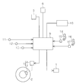
- the vehicle safety device shown in FIG. 1 is a system that performs various types of vehicle control, such as drive control of a brake device 1 that brakes a traveling vehicle, and drive control of a notification device 7 that issues an alarm to a driver of the vehicle.
- An ECU 9 is provided.
- the brake device 1 includes a brake caliper 3 for restricting the rotation of the wheel 2 and an actuator 4 for driving the brake caliper 3.
- the notification device 7 any one of a warning light, a buzzer, a display, and the like can be adopted.
- the system ECU 9 includes a steering angle sensor 11 that detects the steering angle of the steered wheels when the vehicle turns, a yaw rate sensor 12 that detects the change speed of the rotation angle when the vehicle turns, and the rotation speed of the wheels 2.
- a wheel speed sensor 13 to be detected is connected.
- the system ECU 9 includes a brake sensor 15 that detects that the driver has depressed the brake pedal (brake operation member) 14 to operate the brake device 1 (on operation), and an accelerator pedal (accelerator operation by the driver).
- An accelerator position sensor 17 for detecting the operation amount of the member 16 is connected.
- the vehicle safety device captures a radar 5 that transmits a detection wave such as a millimeter wave forward in the traveling direction of the vehicle and receives a reflected wave when the detection wave is reflected, and images the front in the traveling direction of the vehicle.
- a navigation system 10 that provides support information for driving the vehicle to the driver based on the map information and the current position of the vehicle.
- the system ECU 9 monitors the transmission of the detection wave and the reception of the reflected wave by the radar 5, the time from the transmission of the detection wave to the reception of the reflected wave (propagation time), the detection wave and the reflected wave Based on the frequency difference due to the Doppler effect and the like, and further based on the image taken by the camera 6, information on the object existing in the forward direction of the vehicle is grasped.
- the system ECU 9 moves the living body (such as a pedestrian) to a region adjacent to the road ahead of the traveling direction of the vehicle traveling on the road based on the information regarding the object existing ahead of the traveling direction of the vehicle grasped as described above. And whether or not the pedestrian or the like is moving in the direction crossing the road in the area.
- the system ECU 9 secures the safety of the pedestrian when the pedestrian moves in the direction crossing the road in the area adjacent to the road in the forward direction of the vehicle traveling on the road.
- Perform safe operation examples of such a safe operation include execution of an automatic brake operation that automatically turns on braking by the vehicle brake device 1.
- the execution timing of the safe operation is set at an early stage for the purpose of ensuring the safety of the pedestrian whose movement is difficult to predict such as sudden start.
- the execution timing of the safe operation is set early, the pedestrian may change the direction of movement or stop after the execution of the safe operation. There is.
- the driver of the vehicle feels that the above-mentioned safety operation is performed unnecessarily, there is a problem that the driver feels uncomfortable due to the execution of the unnecessary safety operation.
- the system ECU 9 detects the presence of a pedestrian when the pedestrian moves in a direction crossing the road in a region adjacent to the road in front of the vehicle traveling on the road. It has a function as a control part which changes the execution timing of the said safe operation
- the road conditions in the area where the pedestrian is present include a first situation other than a roadway such as a sidewalk, a second situation that is a roadway and other than an opposite lane, and a roadway that is an opposite lane.
- the third situation is, and so on. Which of the first situation, the second situation, and the third situation exists ahead of the traveling direction of the vehicle ascertained using the radar 5, the camera 6, the navigation system 10, and the like. The determination can be made based on information related to an object (for example, a guardrail or an oncoming vehicle).
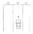
- the road shown in FIG. 2 has a structure including a traffic zone A2 where the vehicle travels, a traffic zone A3 where the vehicle travels in the opposite direction to the traffic zone A2, and a sidewalk A1 adjacent to the traffic zone A2. .
- the traffic zone A3 opposite lane
- the sidewalk A1 are adjacent to the road (traffic zone A2) on which the vehicle travels. Therefore, in this case, the first situation or the third situation described above may occur.
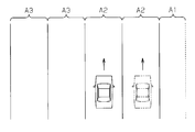
- the road shown in FIG. 3 has a plurality of traffic zones A2 and A3 (two in this example), and a sidewalk A1 is provided adjacent to the traffic zone A2 farthest from the traffic zone A3. It has been.
- the vehicle travels as shown by the solid line in the traffic zone A2 close to the traffic zone A3, the vehicle travels most from the traffic zone A3 (opposite lane) and the traffic zone A3 with respect to the road on which the vehicle travels (the traffic zone A2).
- a separate traffic zone A2 is adjacent. Therefore, in this case, the second situation or the third situation described above may occur.
- the traffic zone A2 farthest from the traffic zone A3 is indicated by a two-dot chain line
- the traffic zone with respect to the road on which the vehicle travels (the above traffic zone A2).
- the lane A2 and the sidewalk A1 near A3 are adjacent. Therefore, in this case, the first situation or the second situation described above may occur.
- the system ECU 9 is configured such that the road situation in the area where the pedestrian is present is a first situation other than a roadway, a second situation where the roadway is a roadway and other than an opposite lane, and a roadway and an opposite lane. It is determined which of the third situations, and the execution timing of the safe operation is delayed in the order of the third situation, the second situation, and the first situation.
- the certainty of crossing varies depending on the road conditions in the area where the pedestrian is present. That is, the possibility that the pedestrian crosses the road on which the vehicle is traveling increases in the order that the road situation is the first situation, the second situation, and the third situation. In other words, there is a high possibility that the pedestrian does not cross the road on which the vehicle travels in the order of the third situation, the second situation, and the first situation.
- the execution timing of the safety operation is delayed in the order of the first situation, the second situation, and the third situation, thereby ensuring the safety of the mobile living body.
- An appropriate timing can be set for suppressing the execution of unnecessary safety operations. Specifically, the higher the possibility that the moving living body is about to cross the road on which the vehicle is traveling, the earlier the execution timing of the safe operation, the more secure the moving living body is secured. On the other hand, as the possibility that the moving living body does not cross the road on which the vehicle travels is increased, unnecessary execution of the safety operation is suppressed by delaying the execution timing of the safety operation.
- FIG. 4 is a flowchart showing a safe operation execution routine for starting the safe operation.
- the safe operation execution routine is periodically executed through the system ECU 9 by, for example, a time interruption at predetermined time intervals.
- step 101 (S101) of the routine the system ECU 9 determines whether or not the flag F used to determine whether or not the safe operation is being executed is “0 (not being executed)”. Make a decision. If a negative determination is made here, the system ECU 9 once ends the safe operation execution routine. On the other hand, if the determination in S101 is affirmative, the process proceeds to S102. As a process of S102, the system ECU 9 uses the radar 5, the camera 6, the navigation system 10, and the like to grasp an object existing ahead in the traveling direction of the vehicle, and based on the information related to the object, the traveling direction of the vehicle traveling on the road It is determined whether or not there is a pedestrian in the area that is ahead and adjacent to the road.
- the system ECU 9 uses the information about the pedestrian ascertained using the radar 5 and the camera 6 as well as the yaw rate sensor 12 and the wheel speed sensor 13 as the processing of S103. On the basis of the information regarding the vehicle to be determined, it is determined whether or not the moving direction of the pedestrian is a direction crossing the road on which the vehicle travels.
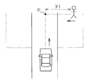
- the system ECU 9 If the determination is negative in either S102 or S103, the system ECU 9 once terminates the safe operation execution routine. On the other hand, if an affirmative determination is made in both S102 and S103, the system ECU 9 executes a series of processes (S104 to S109) for executing a safe operation. In this series of processes, the system ECU 9 determines that when the distance X1 from the pedestrian to the intersection P (intersection P shown in FIG. 5) between the moving direction of the pedestrian and the traveling direction of the vehicle is less than the threshold A1. Perform the above safe operation. Accordingly, as the threshold A1 is set to a larger value, the execution timing of the safe operation is earlier (the safe operation is performed in a state where the pedestrian is far from the intersection P). On the other hand, as the threshold A1 is set to a smaller value, the execution timing of the safe operation is delayed (the safe operation is performed in a state where the pedestrian is close to the intersection P).
- the system ECU 9 obtains an intersection P between the moving direction of the pedestrian and the traveling direction of the vehicle in the process of S104 of FIG. 4, and obtains a distance X1 from the pedestrian to the intersection P.
- the traveling direction of the vehicle is obtained based on the change speed of the rotation angle when the vehicle turns detected by the yaw rate sensor 12, the steering angle of the steering wheel detected by the steering angle sensor 11, and the like.
- the system ECU 9 determines whether the road situation in the area where the pedestrian is present is one of the first situation, the second situation, and the third situation as the process of S105.
- the system ECU 9 variably sets the threshold value A1 according to the determination result of the road condition as the process of S106.
- the threshold value A1 is variably set so that the threshold value A1 becomes a smaller value in the order of the road condition being the third condition, the second condition, and the first condition.
- the system ECU 9 determines whether or not the distance X1 is less than the threshold value A1 as a process of S107. When the distance X1 is equal to or greater than the threshold value A1, the system ECU 9 once ends this safe operation execution routine. On the other hand, when the distance X1 is less than the threshold value A1, the system ECU 9 executes a safe operation as the process of step S108, and then sets the flag F to “1 (execution)” as the process of S109. The execution timing of the safe operation is delayed in the order of the third situation, the second situation, and the first situation in the road situation of the area where the pedestrian exists due to the variable setting of the threshold value A1.
- the system ECU 9 changes the braking force based on the automatic braking operation in accordance with the road condition of the area where the pedestrian exists when performing the automatic braking operation with the execution of the safety operation.
- the road situation of the area where the pedestrian is present is a situation where the operation timing of the safe operation is earlier, in other words, the road situation is the first situation, the second situation, and the third situation. In order, the braking force based on the automatic braking operation is increased.
- FIG. 6 is a flowchart showing a safe operation stop routine for stopping the safe operation being executed.
- This safe operation stop routine is also periodically executed through the system ECU 9 by, for example, a time interruption at predetermined time intervals.
- the system ECU 9 determines whether or not the flag F is “1 (execution)” as the process of S201 of the routine, and if the determination is affirmative, the road in the region where the pedestrian exists is determined as a process of S202. It is determined whether the situation is the first situation. When the road condition of the area where the pedestrian is present is the first condition, the system ECU 9 determines whether or not the accelerator pedal 16 is turned on as a process of S203, and performs a brake as a process of S204. It is determined whether or not the pedal 14 is turned on. If a negative determination is made in both S203 and S204, the system ECU 9 once ends this safe operation stop routine. On the other hand, if an affirmative determination is made in either S203 or S204, the system ECU 9 stops the safety operation being executed as the processing of S205 and sets the flag F to “0”, and then the safety operation stop routine. Exit.
- step S207 the system ECU 9 determines whether or not the brake pedal 14 is turned on. If the determination is affirmative, the system ECU 9 proceeds to step S205 and stops the safety operation being executed.
- a negative determination is made in S206, in other words, when the road situation of the area where the pedestrian is present is the third situation, the system ECU 9 once ends the safe operation stop routine. Even when a negative determination is made in S207, the system ECU 9 once ends the safe operation stop routine.
- the system ECU 9 The execution timing of the safety operation for ensuring the safety of the pedestrian is changed according to the road condition of the existing area.
- the road situation in the area where the pedestrian is present is the first situation other than the roadway, the second situation that is the roadway and other than the opposite lane, and the roadway and the opposite lane. It is determined which of the third situations, and the execution timing of the safe operation is delayed in the order of the third situation, the second situation, and the first situation.
- the execution timing of the safety operation is delayed in the order of the first situation, the second situation, and the third situation, thereby ensuring the safety of the pedestrian.
- An appropriate timing can be set for suppressing the execution of unnecessary safety operations.
- the safety of the pedestrian is ensured by increasing the execution timing of the safety operation as the possibility that the pedestrian is about to cross the road on which the vehicle travels is increased.
- the execution timing of the safety operation is delayed, thereby suppressing unnecessary execution of the safety operation.
- the system ECU 9 executes the safety operation when the distance X1 from the pedestrian to the intersection P between the extension line in the moving direction of the pedestrian and the extension line in the traveling direction of the vehicle is less than the threshold A1. To do.
- the pedestrian moves in a direction crossing the road on which the vehicle travels, it takes time to shorten the distance X1 from the pedestrian to the intersection P. Therefore, the execution timing of the safe operation can be accurately delayed by reducing the threshold value A1.
- the system ECU 9 changes the braking force based on the automatic braking operation in accordance with the road condition of the area where the pedestrian is present when performing the automatic braking operation with the execution of the safety operation.
- the road situation of the area where the pedestrian is present is a situation where the operation timing of the safe operation is earlier, in other words, the road situation is the first situation, the second situation, and the third situation.
- the braking force based on the automatic braking operation is increased. Since the possibility that the pedestrian crosses the road on which the vehicle travels increases in the order that the road situation is the first situation, the second situation, and the third situation, the automatic braking operation is performed as described above. By making the braking force based on the variable, the safety of the pedestrian by the safe operation can be more accurately performed.
- the system ECU 9 changes the stop mode of the safe operation as follows. In other words, during the execution of the safety operation, the system ECU 9 stops the safety operation when the driver performs either the accelerator pedal 16 on operation or the brake pedal 14 on operation in the first situation. To do. Further, during the execution of the safety operation, the system ECU 9 stops the safety operation when the driver turns on the brake pedal 14 in the second situation, and if in the third situation, the system ECU 9 stops the safety action. The driver does not stop the safe operation when the accelerator pedal 16 is turned on or the brake pedal 14 is turned on. Since the possibility that the pedestrian crosses the road on which the vehicle travels increases in the order that the road situation is the first situation, the second situation, and the third situation, The safety of the pedestrian can be ensured more accurately by changing the stop mode of the safe operation.
- the safe operation may be only the execution of an alarm to the driver by the notification device 7 or only the execution of the automatic brake operation.
- an automatic winding operation may be performed in which a seat belt provided in a vehicle seat is automatically wound.
- the vehicle occupant in addition to ensuring the safety of the pedestrian by the safety operation, the vehicle occupant can be protected by the automatic winding operation.
- the stopping mode of the safe operation during execution does not necessarily have to be changed according to the road conditions in the area where the pedestrian exists.
- the braking force When the braking force based on the automatic braking operation accompanying the execution of the safety operation is reduced according to the first situation, the braking force may be “0”. In other words, the automatic braking operation may not be performed.
- the braking force of the automatic braking operation does not necessarily need to be variable according to the road conditions in the area where the pedestrian is present.
- the safe operation is performed when the moving speed of the pedestrian (speed V1 shown in FIG. 7) is equal to or greater than the threshold A3. May be executed.
- the execution timing of the safe operation is delayed by increasing the threshold A3.
- the pedestrian moves in a direction crossing the road on which the vehicle is traveling, it takes time for the movement speed of the pedestrian to increase (fasten). Therefore, by increasing the threshold A3, the safety can be increased.
- the execution timing of the operation can be accurately delayed.
- the speed V1 can be obtained based on information about the pedestrian that is grasped by using the radar 5 and the camera 6 or the like.
- the predicted time T required for the pedestrian to contact the vehicle is less than the threshold value A2.
- a safe operation may be performed.
- the execution timing of the safe operation is delayed by reducing the threshold value A2.
- the prediction timing of the safe operation is set. It can be accurately delayed.
- the predicted time T is obtained by using a time T1 required for the pedestrian to reach the intersection P and a time T2 required for the vehicle to reach the intersection P.
- the said time T1 is calculated
- the time T2 is obtained based on the distance X2 between the vehicle and the intersection P1 and the vehicle speed V2.
- the distance X2 and the speed V2 are information on the pedestrian grasped by using the radar 5 and the camera 6, etc., information on the relative relationship between the pedestrian and the vehicle, and the yaw rate sensor 12 and the wheel speed sensor 13. It is calculated
- the threshold values A1 to A3 are changed depending on whether the road situation of the area where the pedestrian is present is the first situation, the second situation, or the third situation. ⁇ A3 may be changed depending on whether the road is other than the roadway or the roadway. Further, the threshold values A1 to A3 may be changed according to whether the road is a roadway and an opposite lane, or a roadway and other than the opposite lane.
- the threshold values A1 to A3 may be variable.
- pedestrians are illustrated as mobile organisms, not only pedestrians but also bicycles and animals may be included.
Abstract
Description
Claims (9)
- 道路を走行する車両の進行方向前方であって前記道路に隣接する領域に存在する移動生体が同領域内で前記道路を横切る方向に移動するとき、その移動生体の安全を確保するための安全動作を実行する制御部を備える車両の安全装置において、
前記制御部は、前記移動生体の存在する領域の道路状況に応じて、前記安全動作の実行タイミングを変えるように構成される
車両の安全装置。 - 前記制御部は、前記移動生体の存在する領域の道路状況が、車道であって且つ対向車線であるか、或いは、車道であって且つ対向車線以外であるかを判断し、車道であって且つ対向車線以外であるときには、車道であって且つ対向車線であるときよりも、前記安全動作の実行タイミングを遅くするように構成される
請求項1記載の車両の安全装置。 - 前記制御部は、前記移動生体の存在する領域の道路状況が車道であるか、或いは車道以外であるかを判断し、車道以外であるときには車道であるときよりも、前記安全動作の実行タイミングを遅くするように構成される
請求項1記載の車両の安全装置。 - 前記制御部は、前記移動生体の存在する領域の道路状況が、車道以外である第1の状況、車道であって且つ対向車線以外である第2の状況、及び、車道であって且つ対向車線である第3の状況のうちいずれの状況であるかを判断し、前記第3の状況、前記第2の状況、及び前記第1の状況の順で、前記安全動作の実行タイミングを遅くするように構成される
請求項1記載の車両の安全装置。 - 前記制御部は、前記移動生体の移動方向の延長線と車両の進行方向の延長線との交点までの前記移動生体からの距離が閾値A1未満であるときに前記安全動作を実行するものであって、前記閾値A1を小さくすることによって前記安全動作の実行タイミングを遅くするように構成される
請求項2~4のいずれか一項に記載の車両の安全装置。 - 前記制御部は、前記移動生体が車両に接触するまでに要する予測時間が閾値A2未満であるときに前記安全動作を実行するものであって、前記閾値A2を小さくすることによって前記安全動作の実行タイミングを遅くするように構成される
請求項2~4のいずれか一項に記載の車両の安全装置。 - 前記制御部は、前記移動生体の移動速度が閾値A3以上であるときに前記安全動作を実行するものであって、前記閾値A3を大きくすることによって前記安全動作の実行タイミングを遅くするように構成される
請求項2~4のいずれか一項に記載の車両の安全装置。 - 前記安全動作は、車両のブレーキ装置を自動的にオンにする自動ブレーキ動作であり、
前記制御部は、前記移動生体の存在する領域の道路状況が前記安全動作の実行タイミングを早くする状況のときほど、前記自動ブレーキ動作に基づく制動力を大きくするように構成される
請求項2~7のいずれか一項に記載の車両の安全装置。 - 前記制御部は、前記安全動作の実行中、前記第1の状況であれば車両の運転者がアクセル操作部材のオン操作とブレーキ操作部材のオン操作とのいずれかを行ったときに前記安全動作を停止し、前記第2の状況であれば運転者がブレーキ操作部材のオン操作を行ったときに前記安全動作を停止し、前記第3の状況であれば運転者のアクセル操作部材のオン操作やブレーキ操作部材のオン操作では前記安全動作を停止しないように構成される
請求項4記載の車両の安全装置。
Priority Applications (5)
| Application Number | Priority Date | Filing Date | Title |
|---|---|---|---|
| EP12887647.1A EP2916307B1 (en) | 2012-10-30 | 2012-10-30 | Vehicle safety apparatus |
| PCT/JP2012/078027 WO2014068671A1 (ja) | 2012-10-30 | 2012-10-30 | 車両の安全装置 |
| CN201280076692.7A CN104756175B (zh) | 2012-10-30 | 2012-10-30 | 车辆的安全装置 |
| JP2014544099A JP5930060B2 (ja) | 2012-10-30 | 2012-10-30 | 車両の安全装置 |
| US14/439,007 US9440648B2 (en) | 2012-10-30 | 2012-10-30 | Vehicle safety apparatus |
Applications Claiming Priority (1)
| Application Number | Priority Date | Filing Date | Title |
|---|---|---|---|
| PCT/JP2012/078027 WO2014068671A1 (ja) | 2012-10-30 | 2012-10-30 | 車両の安全装置 |
Publications (1)
| Publication Number | Publication Date |
|---|---|
| WO2014068671A1 true WO2014068671A1 (ja) | 2014-05-08 |
Family
ID=50626649
Family Applications (1)
| Application Number | Title | Priority Date | Filing Date |
|---|---|---|---|
| PCT/JP2012/078027 WO2014068671A1 (ja) | 2012-10-30 | 2012-10-30 | 車両の安全装置 |
Country Status (5)
| Country | Link |
|---|---|
| US (1) | US9440648B2 (ja) |
| EP (1) | EP2916307B1 (ja) |
| JP (1) | JP5930060B2 (ja) |
| CN (1) | CN104756175B (ja) |
| WO (1) | WO2014068671A1 (ja) |
Cited By (2)
| Publication number | Priority date | Publication date | Assignee | Title |
|---|---|---|---|---|
| JP2018012360A (ja) * | 2016-07-19 | 2018-01-25 | トヨタ自動車株式会社 | 走行支援装置 |
| WO2019058446A1 (ja) * | 2017-09-20 | 2019-03-28 | 本田技研工業株式会社 | 車両制御装置、車両制御方法、及びプログラム |
Families Citing this family (22)
| Publication number | Priority date | Publication date | Assignee | Title |
|---|---|---|---|---|
| JP6429368B2 (ja) | 2013-08-02 | 2018-11-28 | 本田技研工業株式会社 | 歩車間通信システムおよび方法 |
| US9786178B1 (en) | 2013-08-02 | 2017-10-10 | Honda Motor Co., Ltd. | Vehicle pedestrian safety system and methods of use and manufacture thereof |
| JP6174516B2 (ja) * | 2014-04-24 | 2017-08-02 | 本田技研工業株式会社 | 衝突回避支援装置、衝突回避支援方法、及びプログラム |
| EP3144919B1 (de) * | 2015-09-18 | 2020-06-24 | Continental Automotive GmbH | Vorrichtung und verfahren zur anfahrassistenz für ein kraftfahrzeug |
| JP6805716B2 (ja) * | 2016-01-25 | 2020-12-23 | 株式会社Jvcケンウッド | 表示装置、表示方法、プログラム |
| US20170267280A1 (en) * | 2016-03-15 | 2017-09-21 | GM Global Technology Operations LLC | Systems and methods for feasible state determination in driver command interpreter |
| JP6671033B2 (ja) * | 2016-03-29 | 2020-03-25 | パナソニックIpマネジメント株式会社 | 車両状況判定装置、車両状況判定方法、および車両状況判定プログラム |
| US9925979B2 (en) * | 2016-06-06 | 2018-03-27 | Robert Bosch Gmbh | Autonomous braking failure management in pedestrian protection |
| KR101996418B1 (ko) * | 2016-12-30 | 2019-07-04 | 현대자동차주식회사 | 센서 융합 기반 보행자 탐지 및 보행자 충돌 방지 장치 및 방법 |
| KR102355671B1 (ko) * | 2017-07-13 | 2022-01-26 | 현대자동차주식회사 | 차량 및 그 제어방법 |
| KR102387614B1 (ko) * | 2017-08-17 | 2022-04-15 | 엘지전자 주식회사 | 차량 운전 보조 장치 및 차량 |
| WO2019064490A1 (ja) * | 2017-09-29 | 2019-04-04 | 本田技研工業株式会社 | 車両制御装置、車両制御方法、およびプログラム |
| CN108382294B (zh) * | 2018-01-22 | 2020-05-19 | 北京汽车集团有限公司 | 远光灯控制方法、装置、车辆及存储介质 |
| JP2019156180A (ja) * | 2018-03-13 | 2019-09-19 | 本田技研工業株式会社 | 車両制御装置、車両制御方法、およびプログラム |
| TWM574122U (zh) * | 2018-09-03 | 2019-02-11 | 中國商昆山君磊電器有限公司 | 電動二輪車自動煞車輔助裝置 |
| CN111683851B (zh) * | 2018-12-26 | 2023-09-12 | 百度时代网络技术(北京)有限公司 | 用于自动驾驶的自反向车道的相互避开算法 |
| JP7092702B2 (ja) * | 2019-03-19 | 2022-06-28 | 本田技研工業株式会社 | リスク推定装置及び自動運転装置 |
| CN112242069B (zh) | 2019-07-17 | 2021-10-01 | 华为技术有限公司 | 一种确定车速的方法和装置 |
| KR102648604B1 (ko) | 2019-07-31 | 2024-03-19 | 현대모비스 주식회사 | 차량의 자동 긴급 제동 시스템 및 그 동작 방법 |
| JP6923869B2 (ja) * | 2019-10-15 | 2021-08-25 | 山内 和博 | 自動運転車 |
| EP4011732A1 (en) | 2020-12-09 | 2022-06-15 | Argo AI GmbH | Method for controlling a vehicle when an obstacle is detected in surroundings of the vehicle; control device for a vehicle with an autonomous driving function; computer readable medium and motor vehicle |
| CN113096424B (zh) * | 2021-03-25 | 2022-05-31 | 武汉光庭信息技术股份有限公司 | 一种行人横穿的车辆自动紧急制动方法及系统 |
Citations (5)
| Publication number | Priority date | Publication date | Assignee | Title |
|---|---|---|---|---|
| JP2000251200A (ja) | 1999-03-02 | 2000-09-14 | Mazda Motor Corp | 車両の障害物検出装置 |
| JP2001357498A (ja) * | 2000-06-15 | 2001-12-26 | Mazda Motor Corp | 車両用情報提供装置 |
| JP2007251257A (ja) * | 2006-03-13 | 2007-09-27 | Fujitsu Ten Ltd | 画像認識装置、車両制御装置、画像認識方法および車両制御方法 |
| JP2008003762A (ja) * | 2006-06-21 | 2008-01-10 | Honda Motor Co Ltd | 障害物認識判定装置 |
| JP2011198247A (ja) * | 2010-03-23 | 2011-10-06 | Toyota Motor Corp | 運転支援装置 |
Family Cites Families (9)
| Publication number | Priority date | Publication date | Assignee | Title |
|---|---|---|---|---|
| JP3843502B2 (ja) * | 1996-09-30 | 2006-11-08 | マツダ株式会社 | 車両用動体認識装置 |
| JP3174832B2 (ja) * | 1999-10-27 | 2001-06-11 | 建設省土木研究所長 | 横断歩行者衝突防止システム |
| JP4235090B2 (ja) * | 2003-11-17 | 2009-03-04 | トヨタ自動車株式会社 | 車両走行支援装置 |
| DE102005039103A1 (de) * | 2005-08-18 | 2007-03-01 | Robert Bosch Gmbh | Verfahren für die Erfassung eines Verkehrsraums |
| JP4872552B2 (ja) | 2006-09-13 | 2012-02-08 | 株式会社豊田中央研究所 | 運転支援装置 |
| US8725309B2 (en) * | 2007-04-02 | 2014-05-13 | Panasonic Corporation | Safety driving support apparatus |
| KR101141874B1 (ko) * | 2008-06-04 | 2012-05-08 | 주식회사 만도 | 위험 지역의 검출 장치, 방법 및 그를 이용한 보행자 검출장치 |
| JP5150527B2 (ja) * | 2009-02-03 | 2013-02-20 | 株式会社日立製作所 | 車両用衝突回避支援装置 |
| EP2388756B1 (en) * | 2010-05-17 | 2019-01-09 | Volvo Car Corporation | Forward collision risk reduction |
-
2012
- 2012-10-30 EP EP12887647.1A patent/EP2916307B1/en active Active
- 2012-10-30 WO PCT/JP2012/078027 patent/WO2014068671A1/ja active Application Filing
- 2012-10-30 JP JP2014544099A patent/JP5930060B2/ja active Active
- 2012-10-30 US US14/439,007 patent/US9440648B2/en active Active
- 2012-10-30 CN CN201280076692.7A patent/CN104756175B/zh active Active
Patent Citations (5)
| Publication number | Priority date | Publication date | Assignee | Title |
|---|---|---|---|---|
| JP2000251200A (ja) | 1999-03-02 | 2000-09-14 | Mazda Motor Corp | 車両の障害物検出装置 |
| JP2001357498A (ja) * | 2000-06-15 | 2001-12-26 | Mazda Motor Corp | 車両用情報提供装置 |
| JP2007251257A (ja) * | 2006-03-13 | 2007-09-27 | Fujitsu Ten Ltd | 画像認識装置、車両制御装置、画像認識方法および車両制御方法 |
| JP2008003762A (ja) * | 2006-06-21 | 2008-01-10 | Honda Motor Co Ltd | 障害物認識判定装置 |
| JP2011198247A (ja) * | 2010-03-23 | 2011-10-06 | Toyota Motor Corp | 運転支援装置 |
Cited By (3)
| Publication number | Priority date | Publication date | Assignee | Title |
|---|---|---|---|---|
| JP2018012360A (ja) * | 2016-07-19 | 2018-01-25 | トヨタ自動車株式会社 | 走行支援装置 |
| WO2019058446A1 (ja) * | 2017-09-20 | 2019-03-28 | 本田技研工業株式会社 | 車両制御装置、車両制御方法、及びプログラム |
| US11276312B2 (en) | 2017-09-20 | 2022-03-15 | Honda Motor Co., Ltd. | Vehicle control apparatus, vehicle control method, and program |
Also Published As
| Publication number | Publication date |
|---|---|
| JPWO2014068671A1 (ja) | 2016-09-08 |
| EP2916307B1 (en) | 2021-05-19 |
| JP5930060B2 (ja) | 2016-06-08 |
| EP2916307A1 (en) | 2015-09-09 |
| CN104756175B (zh) | 2018-02-16 |
| US20150298693A1 (en) | 2015-10-22 |
| US9440648B2 (en) | 2016-09-13 |
| CN104756175A (zh) | 2015-07-01 |
| EP2916307A4 (en) | 2016-04-13 |
Similar Documents
| Publication | Publication Date | Title |
|---|---|---|
| JP5930060B2 (ja) | 車両の安全装置 | |
| JP6230620B2 (ja) | 走行制御装置 | |
| JP5700111B2 (ja) | 走行支援装置及び方法 | |
| CN109664882B (zh) | 一种避免道路车辆二次碰撞的方法、系统及电子设备 | |
| CN107792064B (zh) | 车辆控制装置 | |
| US9963128B2 (en) | Travel assistance device | |
| JP5696444B2 (ja) | 走行制御装置 | |
| KR102206689B1 (ko) | 추월지원시스템을 위한 방법 및 장치 | |
| JP5949961B2 (ja) | 運転支援装置 | |
| JP2014093040A (ja) | 衝突回避支援装置及び衝突回避支援方法 | |
| WO2008153205A1 (ja) | 衝突軽減装置 | |
| JP2017186011A (ja) | 車両の制御装置及び車両の走行制御システム | |
| JP2019014454A (ja) | 車両における制動支援装置および制動支援制御方法 | |
| JP5743576B2 (ja) | 物体検出システム | |
| JP5146288B2 (ja) | 車両制御装置 | |
| JP7156957B2 (ja) | 運転支援装置 | |
| JP6805767B2 (ja) | 車両制御システム | |
| JP2011126319A (ja) | 車両の走行安全制御装置 | |
| JP5409530B2 (ja) | 車両運転支援装置 | |
| JP2014096064A (ja) | 車両の運転支援装置及び運転支援方法 | |
| JP2017073060A (ja) | 車線変更支援装置 | |
| JP6132168B2 (ja) | 車両の制御装置 | |
| JP2011129013A (ja) | 走行支援装置 | |
| JP2012232639A (ja) | 走行支援装置及び方法 | |
| JP2012221463A (ja) | 衝突回避装置 |
Legal Events
| Date | Code | Title | Description |
|---|---|---|---|
| 121 | Ep: the epo has been informed by wipo that ep was designated in this application |
Ref document number: 12887647 Country of ref document: EP Kind code of ref document: A1 |
|
| ENP | Entry into the national phase |
Ref document number: 2014544099 Country of ref document: JP Kind code of ref document: A |
|
| WWE | Wipo information: entry into national phase |
Ref document number: 2012887647 Country of ref document: EP |
|
| WWE | Wipo information: entry into national phase |
Ref document number: 14439007 Country of ref document: US |
|
| NENP | Non-entry into the national phase |
Ref country code: DE |