WO2014057820A1 - Système et procédé d'épuration de gaz d'échappement - Google Patents
Système et procédé d'épuration de gaz d'échappement Download PDFInfo
- Publication number
- WO2014057820A1 WO2014057820A1 PCT/JP2013/076347 JP2013076347W WO2014057820A1 WO 2014057820 A1 WO2014057820 A1 WO 2014057820A1 JP 2013076347 W JP2013076347 W JP 2013076347W WO 2014057820 A1 WO2014057820 A1 WO 2014057820A1
- Authority
- WO
- WIPO (PCT)
- Prior art keywords
- temperature
- exhaust gas
- injection
- control
- gas purification
- Prior art date
Links
Images


Classifications
-
- F—MECHANICAL ENGINEERING; LIGHTING; HEATING; WEAPONS; BLASTING
- F02—COMBUSTION ENGINES; HOT-GAS OR COMBUSTION-PRODUCT ENGINE PLANTS
- F02D—CONTROLLING COMBUSTION ENGINES
- F02D41/00—Electrical control of supply of combustible mixture or its constituents
- F02D41/02—Circuit arrangements for generating control signals
- F02D41/14—Introducing closed-loop corrections
- F02D41/1438—Introducing closed-loop corrections using means for determining characteristics of the combustion gases; Sensors therefor
- F02D41/1444—Introducing closed-loop corrections using means for determining characteristics of the combustion gases; Sensors therefor characterised by the characteristics of the combustion gases
- F02D41/1446—Introducing closed-loop corrections using means for determining characteristics of the combustion gases; Sensors therefor characterised by the characteristics of the combustion gases the characteristics being exhaust temperatures
-
- B—PERFORMING OPERATIONS; TRANSPORTING
- B01—PHYSICAL OR CHEMICAL PROCESSES OR APPARATUS IN GENERAL
- B01D—SEPARATION
- B01D53/00—Separation of gases or vapours; Recovering vapours of volatile solvents from gases; Chemical or biological purification of waste gases, e.g. engine exhaust gases, smoke, fumes, flue gases, aerosols
- B01D53/34—Chemical or biological purification of waste gases
- B01D53/92—Chemical or biological purification of waste gases of engine exhaust gases
- B01D53/94—Chemical or biological purification of waste gases of engine exhaust gases by catalytic processes
- B01D53/9404—Removing only nitrogen compounds
- B01D53/9409—Nitrogen oxides
- B01D53/9431—Processes characterised by a specific device
-
- F—MECHANICAL ENGINEERING; LIGHTING; HEATING; WEAPONS; BLASTING
- F01—MACHINES OR ENGINES IN GENERAL; ENGINE PLANTS IN GENERAL; STEAM ENGINES
- F01N—GAS-FLOW SILENCERS OR EXHAUST APPARATUS FOR MACHINES OR ENGINES IN GENERAL; GAS-FLOW SILENCERS OR EXHAUST APPARATUS FOR INTERNAL COMBUSTION ENGINES
- F01N3/00—Exhaust or silencing apparatus having means for purifying, rendering innocuous, or otherwise treating exhaust
- F01N3/02—Exhaust or silencing apparatus having means for purifying, rendering innocuous, or otherwise treating exhaust for cooling, or for removing solid constituents of, exhaust
- F01N3/021—Exhaust or silencing apparatus having means for purifying, rendering innocuous, or otherwise treating exhaust for cooling, or for removing solid constituents of, exhaust by means of filters
- F01N3/023—Exhaust or silencing apparatus having means for purifying, rendering innocuous, or otherwise treating exhaust for cooling, or for removing solid constituents of, exhaust by means of filters using means for regenerating the filters, e.g. by burning trapped particles
- F01N3/025—Exhaust or silencing apparatus having means for purifying, rendering innocuous, or otherwise treating exhaust for cooling, or for removing solid constituents of, exhaust by means of filters using means for regenerating the filters, e.g. by burning trapped particles using fuel burner or by adding fuel to exhaust
-
- F—MECHANICAL ENGINEERING; LIGHTING; HEATING; WEAPONS; BLASTING
- F01—MACHINES OR ENGINES IN GENERAL; ENGINE PLANTS IN GENERAL; STEAM ENGINES
- F01N—GAS-FLOW SILENCERS OR EXHAUST APPARATUS FOR MACHINES OR ENGINES IN GENERAL; GAS-FLOW SILENCERS OR EXHAUST APPARATUS FOR INTERNAL COMBUSTION ENGINES
- F01N3/00—Exhaust or silencing apparatus having means for purifying, rendering innocuous, or otherwise treating exhaust
- F01N3/08—Exhaust or silencing apparatus having means for purifying, rendering innocuous, or otherwise treating exhaust for rendering innocuous
- F01N3/0807—Exhaust or silencing apparatus having means for purifying, rendering innocuous, or otherwise treating exhaust for rendering innocuous by using absorbents or adsorbents
- F01N3/0814—Exhaust or silencing apparatus having means for purifying, rendering innocuous, or otherwise treating exhaust for rendering innocuous by using absorbents or adsorbents combined with catalytic converters, e.g. NOx absorption/storage reduction catalysts
-
- F—MECHANICAL ENGINEERING; LIGHTING; HEATING; WEAPONS; BLASTING
- F01—MACHINES OR ENGINES IN GENERAL; ENGINE PLANTS IN GENERAL; STEAM ENGINES
- F01N—GAS-FLOW SILENCERS OR EXHAUST APPARATUS FOR MACHINES OR ENGINES IN GENERAL; GAS-FLOW SILENCERS OR EXHAUST APPARATUS FOR INTERNAL COMBUSTION ENGINES
- F01N3/00—Exhaust or silencing apparatus having means for purifying, rendering innocuous, or otherwise treating exhaust
- F01N3/08—Exhaust or silencing apparatus having means for purifying, rendering innocuous, or otherwise treating exhaust for rendering innocuous
- F01N3/10—Exhaust or silencing apparatus having means for purifying, rendering innocuous, or otherwise treating exhaust for rendering innocuous by thermal or catalytic conversion of noxious components of exhaust
- F01N3/105—General auxiliary catalysts, e.g. upstream or downstream of the main catalyst
- F01N3/106—Auxiliary oxidation catalysts
-
- F—MECHANICAL ENGINEERING; LIGHTING; HEATING; WEAPONS; BLASTING
- F01—MACHINES OR ENGINES IN GENERAL; ENGINE PLANTS IN GENERAL; STEAM ENGINES
- F01N—GAS-FLOW SILENCERS OR EXHAUST APPARATUS FOR MACHINES OR ENGINES IN GENERAL; GAS-FLOW SILENCERS OR EXHAUST APPARATUS FOR INTERNAL COMBUSTION ENGINES
- F01N3/00—Exhaust or silencing apparatus having means for purifying, rendering innocuous, or otherwise treating exhaust
- F01N3/08—Exhaust or silencing apparatus having means for purifying, rendering innocuous, or otherwise treating exhaust for rendering innocuous
- F01N3/10—Exhaust or silencing apparatus having means for purifying, rendering innocuous, or otherwise treating exhaust for rendering innocuous by thermal or catalytic conversion of noxious components of exhaust
- F01N3/24—Exhaust or silencing apparatus having means for purifying, rendering innocuous, or otherwise treating exhaust for rendering innocuous by thermal or catalytic conversion of noxious components of exhaust characterised by constructional aspects of converting apparatus
- F01N3/36—Arrangements for supply of additional fuel
-
- F—MECHANICAL ENGINEERING; LIGHTING; HEATING; WEAPONS; BLASTING
- F01—MACHINES OR ENGINES IN GENERAL; ENGINE PLANTS IN GENERAL; STEAM ENGINES
- F01N—GAS-FLOW SILENCERS OR EXHAUST APPARATUS FOR MACHINES OR ENGINES IN GENERAL; GAS-FLOW SILENCERS OR EXHAUST APPARATUS FOR INTERNAL COMBUSTION ENGINES
- F01N9/00—Electrical control of exhaust gas treating apparatus
-
- F—MECHANICAL ENGINEERING; LIGHTING; HEATING; WEAPONS; BLASTING
- F02—COMBUSTION ENGINES; HOT-GAS OR COMBUSTION-PRODUCT ENGINE PLANTS
- F02D—CONTROLLING COMBUSTION ENGINES
- F02D41/00—Electrical control of supply of combustible mixture or its constituents
- F02D41/02—Circuit arrangements for generating control signals
- F02D41/021—Introducing corrections for particular conditions exterior to the engine
- F02D41/0235—Introducing corrections for particular conditions exterior to the engine in relation with the state of the exhaust gas treating apparatus
- F02D41/024—Introducing corrections for particular conditions exterior to the engine in relation with the state of the exhaust gas treating apparatus to increase temperature of the exhaust gas treating apparatus
-
- F—MECHANICAL ENGINEERING; LIGHTING; HEATING; WEAPONS; BLASTING
- F02—COMBUSTION ENGINES; HOT-GAS OR COMBUSTION-PRODUCT ENGINE PLANTS
- F02D—CONTROLLING COMBUSTION ENGINES
- F02D41/00—Electrical control of supply of combustible mixture or its constituents
- F02D41/02—Circuit arrangements for generating control signals
- F02D41/021—Introducing corrections for particular conditions exterior to the engine
- F02D41/0235—Introducing corrections for particular conditions exterior to the engine in relation with the state of the exhaust gas treating apparatus
- F02D41/027—Introducing corrections for particular conditions exterior to the engine in relation with the state of the exhaust gas treating apparatus to purge or regenerate the exhaust gas treating apparatus
-
- F—MECHANICAL ENGINEERING; LIGHTING; HEATING; WEAPONS; BLASTING
- F02—COMBUSTION ENGINES; HOT-GAS OR COMBUSTION-PRODUCT ENGINE PLANTS
- F02D—CONTROLLING COMBUSTION ENGINES
- F02D41/00—Electrical control of supply of combustible mixture or its constituents
- F02D41/30—Controlling fuel injection
- F02D41/38—Controlling fuel injection of the high pressure type
- F02D41/40—Controlling fuel injection of the high pressure type with means for controlling injection timing or duration
- F02D41/402—Multiple injections
- F02D41/405—Multiple injections with post injections
-
- F—MECHANICAL ENGINEERING; LIGHTING; HEATING; WEAPONS; BLASTING
- F01—MACHINES OR ENGINES IN GENERAL; ENGINE PLANTS IN GENERAL; STEAM ENGINES
- F01N—GAS-FLOW SILENCERS OR EXHAUST APPARATUS FOR MACHINES OR ENGINES IN GENERAL; GAS-FLOW SILENCERS OR EXHAUST APPARATUS FOR INTERNAL COMBUSTION ENGINES
- F01N11/00—Monitoring or diagnostic devices for exhaust-gas treatment apparatus, e.g. for catalytic activity
- F01N11/002—Monitoring or diagnostic devices for exhaust-gas treatment apparatus, e.g. for catalytic activity the diagnostic devices measuring or estimating temperature or pressure in, or downstream of the exhaust apparatus
-
- F—MECHANICAL ENGINEERING; LIGHTING; HEATING; WEAPONS; BLASTING
- F01—MACHINES OR ENGINES IN GENERAL; ENGINE PLANTS IN GENERAL; STEAM ENGINES
- F01N—GAS-FLOW SILENCERS OR EXHAUST APPARATUS FOR MACHINES OR ENGINES IN GENERAL; GAS-FLOW SILENCERS OR EXHAUST APPARATUS FOR INTERNAL COMBUSTION ENGINES
- F01N2430/00—Influencing exhaust purification, e.g. starting of catalytic reaction, filter regeneration, or the like, by controlling engine operating characteristics
- F01N2430/06—Influencing exhaust purification, e.g. starting of catalytic reaction, filter regeneration, or the like, by controlling engine operating characteristics by varying fuel-air ratio, e.g. by enriching fuel-air mixture
-
- F—MECHANICAL ENGINEERING; LIGHTING; HEATING; WEAPONS; BLASTING
- F01—MACHINES OR ENGINES IN GENERAL; ENGINE PLANTS IN GENERAL; STEAM ENGINES
- F01N—GAS-FLOW SILENCERS OR EXHAUST APPARATUS FOR MACHINES OR ENGINES IN GENERAL; GAS-FLOW SILENCERS OR EXHAUST APPARATUS FOR INTERNAL COMBUSTION ENGINES
- F01N2430/00—Influencing exhaust purification, e.g. starting of catalytic reaction, filter regeneration, or the like, by controlling engine operating characteristics
- F01N2430/08—Influencing exhaust purification, e.g. starting of catalytic reaction, filter regeneration, or the like, by controlling engine operating characteristics by modifying ignition or injection timing
- F01N2430/085—Influencing exhaust purification, e.g. starting of catalytic reaction, filter regeneration, or the like, by controlling engine operating characteristics by modifying ignition or injection timing at least a part of the injection taking place during expansion or exhaust stroke
-
- F—MECHANICAL ENGINEERING; LIGHTING; HEATING; WEAPONS; BLASTING
- F01—MACHINES OR ENGINES IN GENERAL; ENGINE PLANTS IN GENERAL; STEAM ENGINES
- F01N—GAS-FLOW SILENCERS OR EXHAUST APPARATUS FOR MACHINES OR ENGINES IN GENERAL; GAS-FLOW SILENCERS OR EXHAUST APPARATUS FOR INTERNAL COMBUSTION ENGINES
- F01N2560/00—Exhaust systems with means for detecting or measuring exhaust gas components or characteristics
- F01N2560/06—Exhaust systems with means for detecting or measuring exhaust gas components or characteristics the means being a temperature sensor
-
- F—MECHANICAL ENGINEERING; LIGHTING; HEATING; WEAPONS; BLASTING
- F01—MACHINES OR ENGINES IN GENERAL; ENGINE PLANTS IN GENERAL; STEAM ENGINES
- F01N—GAS-FLOW SILENCERS OR EXHAUST APPARATUS FOR MACHINES OR ENGINES IN GENERAL; GAS-FLOW SILENCERS OR EXHAUST APPARATUS FOR INTERNAL COMBUSTION ENGINES
- F01N2560/00—Exhaust systems with means for detecting or measuring exhaust gas components or characteristics
- F01N2560/14—Exhaust systems with means for detecting or measuring exhaust gas components or characteristics having more than one sensor of one kind
-
- F—MECHANICAL ENGINEERING; LIGHTING; HEATING; WEAPONS; BLASTING
- F01—MACHINES OR ENGINES IN GENERAL; ENGINE PLANTS IN GENERAL; STEAM ENGINES
- F01N—GAS-FLOW SILENCERS OR EXHAUST APPARATUS FOR MACHINES OR ENGINES IN GENERAL; GAS-FLOW SILENCERS OR EXHAUST APPARATUS FOR INTERNAL COMBUSTION ENGINES
- F01N2570/00—Exhaust treating apparatus eliminating, absorbing or adsorbing specific elements or compounds
- F01N2570/14—Nitrogen oxides
-
- F—MECHANICAL ENGINEERING; LIGHTING; HEATING; WEAPONS; BLASTING
- F01—MACHINES OR ENGINES IN GENERAL; ENGINE PLANTS IN GENERAL; STEAM ENGINES
- F01N—GAS-FLOW SILENCERS OR EXHAUST APPARATUS FOR MACHINES OR ENGINES IN GENERAL; GAS-FLOW SILENCERS OR EXHAUST APPARATUS FOR INTERNAL COMBUSTION ENGINES
- F01N2610/00—Adding substances to exhaust gases
- F01N2610/03—Adding substances to exhaust gases the substance being hydrocarbons, e.g. engine fuel
-
- F—MECHANICAL ENGINEERING; LIGHTING; HEATING; WEAPONS; BLASTING
- F01—MACHINES OR ENGINES IN GENERAL; ENGINE PLANTS IN GENERAL; STEAM ENGINES
- F01N—GAS-FLOW SILENCERS OR EXHAUST APPARATUS FOR MACHINES OR ENGINES IN GENERAL; GAS-FLOW SILENCERS OR EXHAUST APPARATUS FOR INTERNAL COMBUSTION ENGINES
- F01N2900/00—Details of electrical control or of the monitoring of the exhaust gas treating apparatus
- F01N2900/04—Methods of control or diagnosing
- F01N2900/0408—Methods of control or diagnosing using a feed-back loop
-
- F—MECHANICAL ENGINEERING; LIGHTING; HEATING; WEAPONS; BLASTING
- F01—MACHINES OR ENGINES IN GENERAL; ENGINE PLANTS IN GENERAL; STEAM ENGINES
- F01N—GAS-FLOW SILENCERS OR EXHAUST APPARATUS FOR MACHINES OR ENGINES IN GENERAL; GAS-FLOW SILENCERS OR EXHAUST APPARATUS FOR INTERNAL COMBUSTION ENGINES
- F01N2900/00—Details of electrical control or of the monitoring of the exhaust gas treating apparatus
- F01N2900/06—Parameters used for exhaust control or diagnosing
- F01N2900/08—Parameters used for exhaust control or diagnosing said parameters being related to the engine
-
- F—MECHANICAL ENGINEERING; LIGHTING; HEATING; WEAPONS; BLASTING
- F01—MACHINES OR ENGINES IN GENERAL; ENGINE PLANTS IN GENERAL; STEAM ENGINES
- F01N—GAS-FLOW SILENCERS OR EXHAUST APPARATUS FOR MACHINES OR ENGINES IN GENERAL; GAS-FLOW SILENCERS OR EXHAUST APPARATUS FOR INTERNAL COMBUSTION ENGINES
- F01N2900/00—Details of electrical control or of the monitoring of the exhaust gas treating apparatus
- F01N2900/06—Parameters used for exhaust control or diagnosing
- F01N2900/14—Parameters used for exhaust control or diagnosing said parameters being related to the exhaust gas
- F01N2900/1404—Exhaust gas temperature
-
- F—MECHANICAL ENGINEERING; LIGHTING; HEATING; WEAPONS; BLASTING
- F01—MACHINES OR ENGINES IN GENERAL; ENGINE PLANTS IN GENERAL; STEAM ENGINES
- F01N—GAS-FLOW SILENCERS OR EXHAUST APPARATUS FOR MACHINES OR ENGINES IN GENERAL; GAS-FLOW SILENCERS OR EXHAUST APPARATUS FOR INTERNAL COMBUSTION ENGINES
- F01N2900/00—Details of electrical control or of the monitoring of the exhaust gas treating apparatus
- F01N2900/06—Parameters used for exhaust control or diagnosing
- F01N2900/16—Parameters used for exhaust control or diagnosing said parameters being related to the exhaust apparatus, e.g. particulate filter or catalyst
- F01N2900/1602—Temperature of exhaust gas apparatus
-
- F—MECHANICAL ENGINEERING; LIGHTING; HEATING; WEAPONS; BLASTING
- F01—MACHINES OR ENGINES IN GENERAL; ENGINE PLANTS IN GENERAL; STEAM ENGINES
- F01N—GAS-FLOW SILENCERS OR EXHAUST APPARATUS FOR MACHINES OR ENGINES IN GENERAL; GAS-FLOW SILENCERS OR EXHAUST APPARATUS FOR INTERNAL COMBUSTION ENGINES
- F01N2900/00—Details of electrical control or of the monitoring of the exhaust gas treating apparatus
- F01N2900/06—Parameters used for exhaust control or diagnosing
- F01N2900/16—Parameters used for exhaust control or diagnosing said parameters being related to the exhaust apparatus, e.g. particulate filter or catalyst
- F01N2900/1621—Catalyst conversion efficiency
-
- F—MECHANICAL ENGINEERING; LIGHTING; HEATING; WEAPONS; BLASTING
- F01—MACHINES OR ENGINES IN GENERAL; ENGINE PLANTS IN GENERAL; STEAM ENGINES
- F01N—GAS-FLOW SILENCERS OR EXHAUST APPARATUS FOR MACHINES OR ENGINES IN GENERAL; GAS-FLOW SILENCERS OR EXHAUST APPARATUS FOR INTERNAL COMBUSTION ENGINES
- F01N2900/00—Details of electrical control or of the monitoring of the exhaust gas treating apparatus
- F01N2900/06—Parameters used for exhaust control or diagnosing
- F01N2900/16—Parameters used for exhaust control or diagnosing said parameters being related to the exhaust apparatus, e.g. particulate filter or catalyst
- F01N2900/1626—Catalyst activation temperature
-
- F—MECHANICAL ENGINEERING; LIGHTING; HEATING; WEAPONS; BLASTING
- F01—MACHINES OR ENGINES IN GENERAL; ENGINE PLANTS IN GENERAL; STEAM ENGINES
- F01N—GAS-FLOW SILENCERS OR EXHAUST APPARATUS FOR MACHINES OR ENGINES IN GENERAL; GAS-FLOW SILENCERS OR EXHAUST APPARATUS FOR INTERNAL COMBUSTION ENGINES
- F01N3/00—Exhaust or silencing apparatus having means for purifying, rendering innocuous, or otherwise treating exhaust
- F01N3/02—Exhaust or silencing apparatus having means for purifying, rendering innocuous, or otherwise treating exhaust for cooling, or for removing solid constituents of, exhaust
- F01N3/021—Exhaust or silencing apparatus having means for purifying, rendering innocuous, or otherwise treating exhaust for cooling, or for removing solid constituents of, exhaust by means of filters
- F01N3/023—Exhaust or silencing apparatus having means for purifying, rendering innocuous, or otherwise treating exhaust for cooling, or for removing solid constituents of, exhaust by means of filters using means for regenerating the filters, e.g. by burning trapped particles
- F01N3/025—Exhaust or silencing apparatus having means for purifying, rendering innocuous, or otherwise treating exhaust for cooling, or for removing solid constituents of, exhaust by means of filters using means for regenerating the filters, e.g. by burning trapped particles using fuel burner or by adding fuel to exhaust
- F01N3/0253—Exhaust or silencing apparatus having means for purifying, rendering innocuous, or otherwise treating exhaust for cooling, or for removing solid constituents of, exhaust by means of filters using means for regenerating the filters, e.g. by burning trapped particles using fuel burner or by adding fuel to exhaust adding fuel to exhaust gases
-
- F—MECHANICAL ENGINEERING; LIGHTING; HEATING; WEAPONS; BLASTING
- F01—MACHINES OR ENGINES IN GENERAL; ENGINE PLANTS IN GENERAL; STEAM ENGINES
- F01N—GAS-FLOW SILENCERS OR EXHAUST APPARATUS FOR MACHINES OR ENGINES IN GENERAL; GAS-FLOW SILENCERS OR EXHAUST APPARATUS FOR INTERNAL COMBUSTION ENGINES
- F01N3/00—Exhaust or silencing apparatus having means for purifying, rendering innocuous, or otherwise treating exhaust
- F01N3/08—Exhaust or silencing apparatus having means for purifying, rendering innocuous, or otherwise treating exhaust for rendering innocuous
- F01N3/10—Exhaust or silencing apparatus having means for purifying, rendering innocuous, or otherwise treating exhaust for rendering innocuous by thermal or catalytic conversion of noxious components of exhaust
- F01N3/103—Oxidation catalysts for HC and CO only
-
- F—MECHANICAL ENGINEERING; LIGHTING; HEATING; WEAPONS; BLASTING
- F01—MACHINES OR ENGINES IN GENERAL; ENGINE PLANTS IN GENERAL; STEAM ENGINES
- F01N—GAS-FLOW SILENCERS OR EXHAUST APPARATUS FOR MACHINES OR ENGINES IN GENERAL; GAS-FLOW SILENCERS OR EXHAUST APPARATUS FOR INTERNAL COMBUSTION ENGINES
- F01N3/00—Exhaust or silencing apparatus having means for purifying, rendering innocuous, or otherwise treating exhaust
- F01N3/08—Exhaust or silencing apparatus having means for purifying, rendering innocuous, or otherwise treating exhaust for rendering innocuous
- F01N3/10—Exhaust or silencing apparatus having means for purifying, rendering innocuous, or otherwise treating exhaust for rendering innocuous by thermal or catalytic conversion of noxious components of exhaust
- F01N3/18—Exhaust or silencing apparatus having means for purifying, rendering innocuous, or otherwise treating exhaust for rendering innocuous by thermal or catalytic conversion of noxious components of exhaust characterised by methods of operation; Control
- F01N3/20—Exhaust or silencing apparatus having means for purifying, rendering innocuous, or otherwise treating exhaust for rendering innocuous by thermal or catalytic conversion of noxious components of exhaust characterised by methods of operation; Control specially adapted for catalytic conversion ; Methods of operation or control of catalytic converters
- F01N3/2006—Periodically heating or cooling catalytic reactors, e.g. at cold starting or overheating
- F01N3/2033—Periodically heating or cooling catalytic reactors, e.g. at cold starting or overheating using a fuel burner or introducing fuel into exhaust duct
-
- F—MECHANICAL ENGINEERING; LIGHTING; HEATING; WEAPONS; BLASTING
- F02—COMBUSTION ENGINES; HOT-GAS OR COMBUSTION-PRODUCT ENGINE PLANTS
- F02D—CONTROLLING COMBUSTION ENGINES
- F02D2200/00—Input parameters for engine control
- F02D2200/02—Input parameters for engine control the parameters being related to the engine
- F02D2200/021—Engine temperature
-
- F—MECHANICAL ENGINEERING; LIGHTING; HEATING; WEAPONS; BLASTING
- F02—COMBUSTION ENGINES; HOT-GAS OR COMBUSTION-PRODUCT ENGINE PLANTS
- F02D—CONTROLLING COMBUSTION ENGINES
- F02D41/00—Electrical control of supply of combustible mixture or its constituents
- F02D41/02—Circuit arrangements for generating control signals
- F02D41/021—Introducing corrections for particular conditions exterior to the engine
- F02D41/0235—Introducing corrections for particular conditions exterior to the engine in relation with the state of the exhaust gas treating apparatus
- F02D41/027—Introducing corrections for particular conditions exterior to the engine in relation with the state of the exhaust gas treating apparatus to purge or regenerate the exhaust gas treating apparatus
- F02D41/0275—Introducing corrections for particular conditions exterior to the engine in relation with the state of the exhaust gas treating apparatus to purge or regenerate the exhaust gas treating apparatus the exhaust gas treating apparatus being a NOx trap or adsorbent
-
- F—MECHANICAL ENGINEERING; LIGHTING; HEATING; WEAPONS; BLASTING
- F02—COMBUSTION ENGINES; HOT-GAS OR COMBUSTION-PRODUCT ENGINE PLANTS
- F02D—CONTROLLING COMBUSTION ENGINES
- F02D41/00—Electrical control of supply of combustible mixture or its constituents
- F02D41/02—Circuit arrangements for generating control signals
- F02D41/021—Introducing corrections for particular conditions exterior to the engine
- F02D41/0235—Introducing corrections for particular conditions exterior to the engine in relation with the state of the exhaust gas treating apparatus
- F02D41/027—Introducing corrections for particular conditions exterior to the engine in relation with the state of the exhaust gas treating apparatus to purge or regenerate the exhaust gas treating apparatus
- F02D41/029—Introducing corrections for particular conditions exterior to the engine in relation with the state of the exhaust gas treating apparatus to purge or regenerate the exhaust gas treating apparatus the exhaust gas treating apparatus being a particulate filter
-
- Y—GENERAL TAGGING OF NEW TECHNOLOGICAL DEVELOPMENTS; GENERAL TAGGING OF CROSS-SECTIONAL TECHNOLOGIES SPANNING OVER SEVERAL SECTIONS OF THE IPC; TECHNICAL SUBJECTS COVERED BY FORMER USPC CROSS-REFERENCE ART COLLECTIONS [XRACs] AND DIGESTS
- Y02—TECHNOLOGIES OR APPLICATIONS FOR MITIGATION OR ADAPTATION AGAINST CLIMATE CHANGE
- Y02T—CLIMATE CHANGE MITIGATION TECHNOLOGIES RELATED TO TRANSPORTATION
- Y02T10/00—Road transport of goods or passengers
- Y02T10/10—Internal combustion engine [ICE] based vehicles
- Y02T10/12—Improving ICE efficiencies
-
- Y—GENERAL TAGGING OF NEW TECHNOLOGICAL DEVELOPMENTS; GENERAL TAGGING OF CROSS-SECTIONAL TECHNOLOGIES SPANNING OVER SEVERAL SECTIONS OF THE IPC; TECHNICAL SUBJECTS COVERED BY FORMER USPC CROSS-REFERENCE ART COLLECTIONS [XRACs] AND DIGESTS
- Y02—TECHNOLOGIES OR APPLICATIONS FOR MITIGATION OR ADAPTATION AGAINST CLIMATE CHANGE
- Y02T—CLIMATE CHANGE MITIGATION TECHNOLOGIES RELATED TO TRANSPORTATION
- Y02T10/00—Road transport of goods or passengers
- Y02T10/10—Internal combustion engine [ICE] based vehicles
- Y02T10/40—Engine management systems
Definitions
- the present invention improves the low temperature characteristics of the exhaust gas purification device including the front-stage oxidation catalyst and at least one of the NOx purification catalyst or DPF, and improves the NOx purification rate at low temperatures and prevents the generation of white smoke.
- the present invention relates to an exhaust gas purification system and an exhaust gas purification method.
- NOx purification catalysts In internal combustion engines such as diesel engines and some gasoline engines, NOx purification catalysts (deNOx catalysts) and DPFs (diesel particles) are used to reduce NOx (nitrogen oxides) and PM (particulate matter) in the exhaust gas. Curate filter) is used.
- the NOx purification catalyst includes a lean NOx trap catalyst (LNT catalyst) and a selective reduction catalyst (SCR catalyst).
- LNT catalyst lean NOx trap catalyst
- SCR catalyst selective reduction catalyst
- One of the lean NOx trap catalysts is a NOx occlusion reduction catalyst.
- This NOx occlusion reduction type catalyst is a NOx occlusion material that occludes NOx and a catalyst that supports a noble metal, and the inflowing exhaust gas has a lean (excessive oxygen) state and oxygen (O 2 ) in the atmosphere.
- NO 2 nitrogen dioxide
- a NOx storage material such as barium (Ba) to form nitrate. (Ba 2 NO 4 ) and the like are occluded.
- the NOx storage material becomes carbon monoxide (CO ) And nitrate is decomposed to release nitrogen dioxide.
- the released nitrogen dioxide is reduced by unburned hydrocarbons (HC) and carbon monoxide contained in the exhaust gas by the three-way function of precious metals to become nitrogen (N 2 ), and various components in the exhaust gas Are released into the atmosphere as harmless substances such as carbon dioxide (CO 2 ), water (H 2 O), and nitrogen.
- the control for reducing the oxygen concentration of the inflowing exhaust gas by making the air-fuel ratio of the exhaust gas rich that is, By performing rich control for NOx storage capacity recovery, the absorbed NOx is released, and NOx regeneration operation is performed in which the released NOx is reduced to nitrogen by a noble metal.
- This NOx occlusion reduction type catalyst in general, the catalytic action is not activated unless the catalyst temperature is higher than the activation temperature. Therefore, the catalytic reaction is not promoted at low temperatures when the catalyst is not activated, and the NOx occlusion reduction type catalyst.
- a NOx purification catalyst such as a catalyst or a selective reduction catalyst has a problem that the NOx purification rate becomes low.
- temperature rise control of the exhaust gas has been studied also in the exhaust gas treatment of the diesel engine.
- This temperature increase control is performed in a cylinder (in the cylinder in the expansion stroke after the top dead center of the piston by multi-stage temperature increase injection (multi-injection), which is a combination of pre-injection (pilot injection), main injection (main injection), after-injection,
- multi-injection multi-stage temperature increase injection
- pilot injection pilot injection
- main injection main injection
- after-injection This is a control for raising the exhaust gas temperature while maintaining the combustion temperature in the cylinder
- the exhaust gas temperature can be raised at an early stage, and the activity of the catalyst of the exhaust gas purification device disposed in the exhaust passage can be accelerated.
- PM regeneration control is performed in which the temperature of the DPF is raised to a temperature equal to or higher than the temperature at which the collected PM starts combustion, and the PM is combusted and removed.
- temperature rise control is performed to raise the temperature of the exhaust gas flowing into the DPF and raise the temperature of the DPF with a high-temperature exhaust gas.
- This HC slip is the same not only when the NOx purification catalyst is cold or when the NOx storage reduction type catalyst is used for NOx regeneration, but also when PM regeneration is used to burn and remove PM in the DPF when the engine is at a low load. May occur.
- an early oxidation catalyst (DOC) and a DPF are used to reduce the release of HC (hydrocarbon) into the atmosphere.
- This is an exhaust gas purification device that performs DOC temperature increase by post injection and DPF temperature increase by oxidation reaction heat in DOC of unburned components supplied by late post injection. It delays a certain time with respect to the target late post injection amount.
- Providing an exhaust emission control device for a diesel engine that suppresses a rapid increase in the injection amount of late post injection and prevents HC slip is provided.
- the DOC that oxidizes the unburned components (unburned HC) in the exhaust gas needs to cover the entire operation region of the internal combustion engine, so that it can be downsized. It is difficult and there is a limit to installing it near the engine body.
- DOC pre-stage oxidation catalyst
- DPF oxidation catalyst
- an exhaust gas purification device that performs DPF temperature rise by oxidation reaction heat in DOC of unburned components supplied by late post injection unburned HC components are externally introduced after DOC reaches the activation temperature after early post injection.
- the oil circulation pump power is increased by increasing the power of the oil circulation pump until the start of early post injection, thereby increasing the exhaust gas temperature rising gradient in the DOC temperature rising stage.
- the present invention has been made to solve the above-mentioned problems, and its object is to improve the low-temperature characteristics of an exhaust gas purification apparatus including a pre-stage oxidation catalyst (DOC) and at least one of a NOx purification catalyst or a DPF.
- DOC pre-stage oxidation catalyst
- NOx purification catalyst or a DPF.
- Exhaust gas that can improve the NOx purification characteristics of the NOx purification catalyst for low temperature exhaust gas, and prevent white smoke from being generated by HC slip during NOx purification, NOx regeneration, and PM regeneration at low temperatures
- a purification system and an exhaust gas purification method are provided.
- An exhaust gas purification system for achieving the above object is provided with an exhaust gas purification device including a pre-stage oxidation catalyst and at least one of a NOx purification catalyst or a DPF in an exhaust passage of the internal combustion engine, and the internal combustion engine.
- an exhaust gas purification device provided with a control device for controlling the operation of the exhaust gas purification system, a first exhaust gas temperature sensor, a pre-oxidation catalyst, and a second exhaust gas temperature sensor are arranged upstream in the exhaust passage upstream of the exhaust gas purification device.
- post injection is performed in addition to the multistage temperature rising injection, and the second temperature detected by the second exhaust gas temperature sensor is preset. Configured to implement a first control for feedback controlling the post injection such that the second set temperature.
- DOC front-stage oxidation catalyst
- Pre-DOC catalyst
- the pre-oxidation catalyst allows the multi-stage temperature rising injection in the cylinder from the cylinder. Efficiently oxidizes unburned HC in the exhaust gas flowing out, prevents HC slip, and efficiently exhaust gas, pre-oxidation catalyst, NOx purification catalyst, DPF, etc. by oxidation heat of HC oxidized by pre-oxidation catalyst
- the temperature can be raised well, and the NOx purification rate can be improved and the efficiency of DPF regeneration can be improved.
- This pre-oxidation catalyst is mainly used to oxidize HC and CO immediately after being discharged from the cylinder.
- the operating state of the internal combustion engine is in an idle state or a low-load exhaust gas temperature is low. Only when the amount of gas is small, it is only necessary to fulfill the function of raising the exhaust gas.
- the capacity can be formed with a small oxidation catalyst having a space velocity SV value of about 100,000 / h (hr ⁇ 1 ).
- this pre-oxidation catalyst can be made small, it can be installed as close as possible to the engine body of the internal combustion engine. Note that this pre-oxidation catalyst alone cannot cover the entire operation region of the internal combustion engine, and the range that cannot be covered is covered by the pre-stage oxidation catalyst (DOC). Therefore, an upstream oxidation catalyst for the exhaust gas purification device is also required.
- DOC pre-stage oxidation catalyst
- first, multistage temperature rising injection or post injection is performed in the cylinder, and HC in the exhaust gas discharged from the cylinder is oxidized by the pre-oxidation catalyst to raise the temperature of the exhaust gas.
- the pre-oxidation catalyst is heated to the catalyst activation temperature at an early stage by multistage temperature rising injection, and after this temperature increase, the HC supplied by post-injection is oxidized by the pre-oxidation catalyst to raise the exhaust gas. Warm up. Thereby, the temperature of the pre-stage oxidation catalyst of the exhaust gas purification device can be raised.
- the pre-oxidation catalyst that can be installed close to the engine body and that is small in size and has a small heat capacity rises very quickly and exceeds the catalyst activation temperature. It can be oxidized efficiently from an early stage.
- the multi-stage temperature rising injection referred to here is in-cylinder fuel injection including pre-injection, main injection, and after-injection.
- the NOx purification catalyst is provided to constitute the exhaust gas purification device.
- the first set temperature is set to the catalyst activation temperature of the pre-oxidation catalyst
- the second The set temperature is set to a temperature at which the catalytic activity of the NOx purification catalyst is good, and the control device controls the first control when the temperature of the cooling water of the internal combustion engine is lower than a preset temperature for cooling water.
- the control for terminating the multistage temperature rising injection and the post injection is performed. .
- the temperature at which the catalytic activity of the NOx purification catalyst is good is one temperature within a temperature range that is not lower than the catalyst activation temperature of the NOx purification catalyst and has a relatively high NOx purification rate.
- the temperature is the highest at the NOx purification rate, the temperature at which the NOx purification rate is within an allowable range, and the most preferable temperature from the viewpoint of the life of the NOx purification catalyst.
- the pre-oxidation catalyst and the first control are used to increase the multistage temperature. Since HC slip that may occur due to injection can be prevented, it is possible to perform multi-stage temperature rising injection from the cold, and early control of the exhaust gas, the front-stage oxidation catalyst, and the NOx purification catalyst by the first control during the cold The temperature can be raised, and the NOx purification rate in the NOx purification catalyst can be improved.
- the DPF is provided to constitute the exhaust gas purification device, and exhaust gas flowing into the exhaust pipe fuel injection device and the DPF is introduced into the exhaust passage upstream of the DPF.
- a temperature at which the fuel injected from the apparatus is decomposed, a third set temperature is set to a temperature at which the particulate matter trapped in the DPF is combustible, and the control device is set to a low temperature of the internal combustion engine.
- the fuel injection device in the exhaust pipe The post-injection is feedback controlled so that the third temperature detected by the third exhaust gas temperature sensor becomes the third set temperature, and is collected by the DPF during the feedback control. And control to end the multi-stage temperature rising injection and the post-injection when it is determined that the particulate matter collected in the DPF has been removed by combustion. To be configured.
- the pre-oxidation catalyst and the first control prevent HC slip that may occur due to multistage temperature rising injection during PM regeneration of the DPF when the operating state of the internal combustion engine is in a low load state. Therefore, even when the load is low, multi-stage temperature rising injection is possible, and the temperature of the exhaust gas can be reached early at the temperature at which the fuel injected by the exhaust pipe fuel injection device is decomposed by the first control, The effect of preventing HC slip can be obtained, and at the same time, the effect of promoting the temperature rise during the PM regeneration of the DPF can be obtained, the DPF can be raised quickly, and the PM can be removed efficiently.
- this pre-oxidation catalyst is more effective when combined with the fuel injection device in the exhaust pipe.
- the distance between the fuel injection device in the exhaust pipe and the front stage oxidation catalyst for example, 1 m or more.
- the pre-oxidation catalyst arranged on the upstream side of the fuel injection device in the exhaust pipe is close to the engine body, high-temperature exhaust gas discharged from the cylinder flows in, although it will be arranged at a distant position.
- the pre-oxidation catalyst can quickly rise above the catalyst activation temperature, and HC supplied by post injection can be oxidized early. The exhaust gas can be quickly heated.
- An exhaust gas purifying method for achieving the above object is to pass exhaust gas discharged from an internal combustion engine through an exhaust gas purifying device having a pre-stage oxidation catalyst and at least one of a NOx purifying catalyst or a DPF.
- the exhaust gas is passed through a pre-oxidation catalyst and then passed through the exhaust gas purification device, and is detected by a first exhaust gas temperature sensor upstream of the exhaust gas purification device.
- a first exhaust gas temperature sensor upstream of the exhaust gas purification device.
- multistage temperature rising injection is performed by in-cylinder combustion control.
- the multistage temperature rising injection is added.
- Post-injection, and the post-injection is fed back so that the temperature detected by the second exhaust gas temperature sensor on the downstream side of the exhaust gas purification device becomes a preset second set temperature.
- the pre-oxidation catalyst and the pre-oxidation catalyst disposed near the upstream cylinder (inside the cylinder) than the exhaust gas purification device including at least one of the NOx purification catalyst or the DPF Since the exhaust gas that is hotter than the exhaust gas flowing into the front-stage oxidation catalyst is made to flow more easily and activated, this pre-oxidation catalyst allows unburned exhaust gas that flows out of the cylinder by multistage temperature rising injection in the cylinder.
- HC can be oxidized efficiently, HC slip can be prevented, and the exhaust gas, pre-oxidation catalyst, NOx purification catalyst, DPF, etc. can be efficiently heated by the oxidation heat of HC oxidized by the pre-oxidation catalyst, NOx purification rate Can be improved and the efficiency of DPF regeneration can be improved.
- the exhaust gas is allowed to pass through the exhaust gas purification device including the NOx purification catalyst, and the first set temperature is set to the catalyst activation temperature of the pre-oxidation catalyst.
- the first control is performed when the set temperature is set to a temperature at which the catalytic activity of the NOx purification catalyst is good, and the temperature of the cooling water of the internal combustion engine is lower than a preset temperature for cooling water.
- the second temperature can maintain the second set temperature by performing the first control, the multi-stage temperature rising injection and the post injection are terminated.
- the pre-oxidation catalyst and the first control are used to increase the multistage temperature. Since HC slip that may occur due to injection can be prevented, it is possible to perform multi-stage temperature rising injection from the cold, and early control of the exhaust gas, the front-stage oxidation catalyst, and the NOx purification catalyst by the first control during the cold The temperature can be raised, and the NOx purification rate in the NOx purification catalyst can be improved.
- the exhaust gas is allowed to pass through the exhaust gas purification device including the DPF, and the first set temperature is set to the catalyst activation temperature of the pre-oxidation catalyst.
- 2 sets the set temperature to a temperature at which the fuel injected from the exhaust pipe fuel injection device decomposes, and sets the third set temperature to a temperature at which the particulate matter collected in the DPF can burn, and
- the first control is performed at a low load of the internal combustion engine and the second temperature can maintain the second set temperature by the first control, the first control is performed upstream of the exhaust gas purification device.
- Fuel injection is started from the provided exhaust pipe fuel injection device, and the post is set so that the third temperature detected by the third exhaust gas temperature sensor arranged upstream of the DPF becomes the third set temperature.
- the feedback control is performed to determine whether the particulate matter collected in the DPF is burned and removed during the feedback control, and the particulate matter collected in the DPF is judged to be burned and removed. Then, the multistage temperature rising injection and the post injection are finished.
- the pre-oxidation catalyst and the first control prevent HC slip that may occur due to multi-stage temperature rising injection during PM regeneration of the DPF when the operating state of the internal combustion engine is in a low load state. Therefore, even when the load is low, multi-stage temperature rising injection is possible, and the temperature of the exhaust gas can be reached early by the first control to the temperature at which the fuel injected by the fuel injection device in the exhaust pipe is decomposed, The effect of preventing HC slip can be obtained, and at the same time, the effect of promoting the temperature rise during the PM regeneration of the DPF can be obtained, the DPF can be raised quickly, and the PM can be removed efficiently.
- an arrangement is adopted in which a pre-oxidation catalyst is installed upstream of the pre-stage oxidation catalyst and an exhaust gas purification device having at least one of a NOx purification catalyst or a DPF.
- a pre-oxidation catalyst is installed upstream of the pre-stage oxidation catalyst and an exhaust gas purification device having at least one of a NOx purification catalyst or a DPF.
- the multistage temperature rising injection and post injection in the first control when the exhaust gas is at a low temperature, the temperature rise of the exhaust gas, the pre-stage oxidation catalyst, the NOx purification device, the DPF, etc. can be achieved at an early stage.
- NOx purification, NOx regeneration, and DPF regeneration can be performed efficiently.
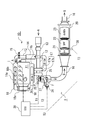
- FIG. 1 is a diagram showing a configuration of an exhaust gas purification system according to a first embodiment of the present invention.
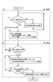
- FIG. 2 is a diagram showing a flow of the first control and the second control according to the present invention.
- FIG. 3 is a diagram showing a flow of the first control and the third control according to the present invention.
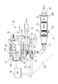
- FIG. 4 is a diagram showing a configuration of an exhaust gas purification system according to a second embodiment of the present invention.
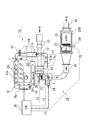
- FIG. 5 is a diagram showing a configuration of an exhaust gas purification system according to a third embodiment of the present invention.
- FIG. 6 is a diagram showing a configuration of an exhaust gas purification system according to a fourth embodiment of the present invention.
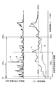
- FIG. 7 is a diagram showing an example of a time series of temperatures at the outlet position of the pre-oxidation catalyst and a time series of NOx concentration at the outlet position of the NOx purification catalyst in the example and the conventional example.
- FIG. 1 shows a configuration of an exhaust gas purification system 1 according to a first embodiment of the present invention.
- the exhaust gas purification system 1 is a system for purifying exhaust gas G of an engine (internal combustion engine) 10, and the engine 10 is an intake passage connected to an engine body 11 and an intake manifold 11 a of the engine body 11. 12, an exhaust passage 16 connected to the exhaust manifold 11 b of the engine body 11, and an EGR passage 18 connecting the exhaust passage 16 and the intake passage 12.
- an intake air amount sensor (MAF) 13 In the intake passage 12 through which the intake air A passes, an intake air amount sensor (MAF) 13, a compressor 17 a of a turbo-type supercharger 17, an intercooler 14, an intake valve 15, etc. are disposed in order from the upstream side.
- a turbine 17b of the turbocharger 17, an HC injection nozzle (fuel injection device in exhaust pipe) 24, an exhaust gas purification device 20 and the like are arranged in order from the upstream side.
- an EGR cooler 18a and an EGR valve 18b are arranged in this order from the upstream side.
- the exhaust gas purification device 20 includes a front-stage oxidation catalyst (DOC) 21, a DPF (diesel particulate filter) 22, and a NOx purification catalyst (deNOx catalyst) 23 in order from the upstream side.
- DOC front-stage oxidation catalyst
- DPF diesel particulate filter
- NOx purification catalyst deNOx catalyst
- DOC front-stage oxidation catalyst
- LNT catalyst NOx occlusion reduction type catalyst
- SCR catalyst selective reduction type catalyst
- a small pre-oxidation catalyst (Pre-DOC) 25 is disposed between the turbine 17b and the HC injection nozzle 24 in the exhaust gas purification system 1 of FIG. Hydrocarbon (HC) flowing out (slip) from the cylinder is oxidized, and the exhaust gas is heated by the oxidation heat of the hydrocarbon.
- Pre-DOC pre-oxidation catalyst
- the capacity of the small pre-oxidation catalyst 25 can generally ensure catalytic activity and efficiently oxidize HC in the range of the exhaust gas flow rate when the operating state of the engine 10 is from an idle operation state to a low load operation state.
- the capacity is set so that the SV value of the space velocity is about 100,000 / h (hr ⁇ 1 ) so as to be within the range.
- the space velocity is obtained by dividing the gas flow rate (Nm 3 / h) by the catalyst amount (m 3 ).
- the capacity of the front-stage oxidation catalyst 21 is formed with a capacity that can efficiently oxidize HC even with respect to the maximum exhaust gas flow rate in the entire range of the operating state of the engine 10, Since it is necessary to be able to cover, the pre-oxidation catalyst 21 is larger than the pre-oxidation catalyst 25.
- the pre-oxidation catalyst 25 can be made smaller than the pre-oxidation catalyst 21.
- the pre-oxidation catalyst 25 can be disposed closer to the engine body 11 than the pre-stage oxidation catalyst 21, so that the temperature of the exhaust gas G discharged from the cylinder is adjusted to the exhaust passage 16.
- the high-temperature exhaust gas G is caused to flow into the pre-oxidation catalyst 25, and the temperature of the pre-oxidation catalyst 25 is raised and maintained above the catalyst activation temperature to oxidize HC and CO. become able to.
- the first exhaust gas temperature sensor 26 is disposed upstream of the pre-oxidation catalyst 25, and the second exhaust gas temperature sensor 27 is disposed downstream of the pre-oxidation catalyst 25. Further, the third exhaust gas temperature sensor 28 is disposed between the upstream oxidation catalyst 21 and the DPF 22 of the exhaust gas purification device 20, that is, upstream of the DPF 22.
- a control device 30 called an engine control unit (ECU) that controls the engine as a whole is provided.
- the control device 30 includes temperatures T1, T2, and T3 detected by the exhaust gas temperature sensors 26, 27, and 28, a cooling water temperature Tw detected by a cooling water temperature sensor (not shown), and the rotational speed of the engine 10. Ne and load Q are input, and in-cylinder fuel injection of the engine 10 is controlled.
- the control device 30 includes the following first control, second control, and third control in the control.
- the first control is control related to activation of the pre-oxidation catalyst 25, and the first temperature T1 detected by the first exhaust gas temperature sensor 26 is preset as shown in the control flow of FIGS.
- multi-stage temperature rise injection temperature increase multi-injection
- pre-injection pilot injection
- main injection main injection
- after-injection is performed by in-cylinder fuel injection.
- the post-injection is performed in addition to the multi-stage temperature rising injection, the unburned HC supplied by the post injection is oxidized by the pre-oxidation catalyst 25, and the first 2 is a control for feedback control so that the second temperature T2 detected by the exhaust gas temperature sensor 27 becomes a preset second set temperature T2c.
- the first set temperature T1c is set to the catalyst activation temperature (approximately about 200 ° C.) of the pre-oxidation catalyst 25.
- the exhaust gas G can be heated by the multi-stage temperature rising injection until the pre-oxidation catalyst 25 is activated, and the pre-oxidation catalyst 25 can be heated by the heated exhaust gas G.
- the HC supplied by post-injection is oxidized by the catalytic action of the pre-oxidation catalyst 25 to raise the temperature of the exhaust gas G.
- the second temperature T2 can be set to the second set temperature Tc2 that meets the demands of the exhaust gas purification device 20 on the downstream side of the pre-oxidation catalyst 25.
- the second control is a control for the NOx purification catalyst 23, and as shown in the control flow of FIG. 2, the cooling water temperature Tw of the engine 10 is set to a preset cooling water temperature Twc (for example, a water temperature 40).
- Twc for example, a water temperature 40.
- the first control is performed, and the second temperature T2 can be maintained at the second set temperature T2c by the first control. If it becomes, it will be control which complete
- the second set temperature T2c is set to the catalyst activation temperature (approximately about 300 ° C.) of the NOx purification catalyst 23.
- the third control is a control for the DPF 22, and as shown in the control flow of FIG. 3, it is determined whether or not the operating state of the engine 10 is a preset low load state, and is in a low load state.
- the injection of the fuel F from the HC injection nozzle 24 is started. 3.
- the feedback control is performed so that the third temperature T3 detected by the exhaust gas temperature sensor 28 becomes the third set temperature T3c, and PM (particulate matter) collected by the DPF 22 is burned and removed during the feedback control. In this control, the multistage temperature rising injection and the post-injection are terminated when it is determined whether or not PM is burned and removed.
- the second set temperature Tc2 can be burned to a temperature at which the fuel F injected from the HC injection nozzle 24 is decomposed (approximately 300 ° C.), and the PM collected at the third set temperature Tc3 in the DPF 22 can be burned.
- Each temperature is set to approximately (approximately 500 ° C. to 600 ° C.).
- This exhaust gas purification method includes a “first control + second control” control for the NOx purification catalyst 23 as shown in FIG. 2 and a “first control + third control” as shown in FIG. And a method for performing control for regeneration of the DPF 22.
- FIG. 2 and FIG. 3 illustrate the control flow.
- the control flow of FIG. 2 and FIG. 3 is called from the upper control flow as needed when the engine 10 is started, and the steps S11 to S22 are performed. Alternatively, step S11 to step S33 are executed to return to the upper control flow, and this is repeatedly executed as necessary. When the engine 10 is stopped, the process is terminated together with the upper control flow.
- the method for the NOx purification catalyst 23 is a method for improving the NOx purification rate of the NOx purification catalyst 23 immediately after the cold start, and the cooling water temperature Tw of the engine 10 is set in advance. Implemented at lower times.
- the first set temperature T1c is the catalyst activation temperature of the pre-oxidation catalyst 25 (about 200 ° C.)
- the second set temperature T2c is the temperature at which the NOx purification catalyst 23 has a good catalyst activity (about about 300 ° C.). ) Respectively.
- This method is an exhaust gas purification method for purifying exhaust gas G exhausted from the engine 10 by passing it through an exhaust gas purification device 20 having a pre-stage oxidation catalyst 21 and a NOx purification catalyst 23.
- the pre-oxidation catalyst 25 is passed before passing through the exhaust gas purification device 20.
- the first temperature T1 detected by the first exhaust gas temperature sensor 26 on the upstream side of the exhaust gas purification device 20 in step S11 is equal to or higher than the preset first set temperature T1c. If it is low (NO), in step S12, in-cylinder combustion control, multi-stage temperature rising injection including pre-injection, main injection, and after-injection is performed. When 1 temperature T1 becomes 1st preset temperature T1c or more (YES), post injection control which performs post injection in addition to multistage temperature rising injection is implemented at Step S13.
- Steps S11 to S13 are the first control (step S10).
- step S21 it is determined whether or not the second temperature T2 can be maintained at the second set temperature T2c by the first control. If not (NO), the process proceeds to step S13. If it can return and can be maintained (YES), it will go to Step S22 and will end multi stage temperature rising injection and post injection.
- Steps S21 and S22 are the second control (step S20). Note that whether or not the second temperature T2 can maintain the second set temperature T2c is, for example, continued for a preset time or more, and the second temperature T2 is a predetermined value centered on the second set temperature T2c. It can be determined by whether or not the temperature is within the range of the temperature range.
- the multistage injection control is started to raise the temperature of the exhaust gas G.
- This multi-stage temperature rising injection is an injection control that is delayed (retarded) than the normal injection.
- the pre-injection, the main injection, and the after-injection are performed, and the in-cylinder combustion is continued to increase the in-cylinder combustion temperature Is exhausted while maintaining a high temperature, and the temperature of the exhaust gas G is raised.
- the concentration of HC and CO in the exhaust gas G increases, but since it can be adsorbed or oxidized by the pre-oxidation catalyst 25, HC and CO can be purified.
- the first temperature T1 of the exhaust gas G on the upstream side of the pre-oxidation catalyst 25 reaches the first set temperature T1c that is the catalyst activation temperature (approximately 200 ° C.) of the pre-oxidation catalyst 25, post injection is performed.
- the temperature of the pre-oxidation catalyst 25 is raised, and the second temperature T2 of the exhaust gas G downstream of the pre-oxidation catalyst 25 is a temperature at which the catalytic activity of the NOx purification catalyst 23 is good (approximately about 300 ° C.).
- the feedback control is performed so that the second set temperature T2c is as follows.
- the warm-up (warm up) of the engine 10 proceeds, the second temperature T2 of the exhaust gas G rises, and the second temperature T2 of the exhaust gas G becomes the NOx purification catalyst even if there is no multi-stage temperature rising injection or post injection.
- the temperature of the catalytic activity of 23 can be maintained at a good temperature (approximately 300 ° C.), the control is terminated.
- the method for regenerating the DPF 22 is a method for promoting DPF regeneration of the DPF 22, and is performed when the operating state of the engine 10 is a preset low load state.
- the first set temperature T1c is set to the catalyst activation temperature of the pre-stage oxidation catalyst 25, and the second set temperature T2c is set to the temperature at which the fuel F injected from the HC injection nozzle 24 is decomposed.
- This method is an exhaust gas purification method for purifying exhaust gas G exhausted from the engine 10 by passing it through an exhaust gas purification device 20 having a pre-stage oxidation catalyst 21 and a DPF 22. Before passing the purification device 20, the pre-oxidation catalyst 25 is passed.
- the first temperature T1 detected by the first exhaust gas temperature sensor 26 on the upstream side of the exhaust gas purification device 20 in step S11 is higher than the preset first set temperature T1c. If it is low (NO), in step S12, in-cylinder combustion control performs multi-stage temperature rising injection including pre-injection, main injection, and after-injection.
- step S12 in-cylinder combustion control performs multi-stage temperature rising injection including pre-injection, main injection, and after-injection.
- the first temperature T1 becomes equal to or higher than the first set temperature T1c (YES)
- post injection control is performed in which post injection is performed in addition to multi-stage temperature rising injection in step S13.
- Step S11 to S13 are the first control (step S10).
- step S31 subsequent to step S13, it is determined whether or not the second temperature T2 can maintain the second set temperature T2c by the first control. If not (NO), the process returns to step S13 and maintained. If it is possible (YES), in step S32, the fuel in the exhaust pipe is injected from the HC injection nozzle 24 provided upstream of the exhaust gas purification device 20, and the third exhaust gas temperature sensor 28 disposed upstream of the DPF 22 is used. The post-injection is feedback controlled so that the detected third temperature T3 becomes the third set temperature T3c.
- next step S33 it is determined whether or not PM (particulate matter) collected in the DPF 22 is burned and removed during the feedback control, and the PM collected in the DPF 22 is not burned and removed. If it is determined (NO), the process returns to step S32, and if it is determined that the PM collected in the DPF 22 is burned and removed (YES), the multistage temperature rising injection and the post injection are terminated in the next step S34. . Steps S31 to S34 are the third control (step S30).
- Whether or not this PM has been burned and removed depends on whether or not the regeneration time that is the total time of fuel injection in the exhaust pipe has passed a preset regeneration target time, and the differential pressure value before and after the DPF 22 is equal to or less than the differential pressure target value. It can be determined by whether or not.
- multistage temperature rising injection is started to raise the temperature of the exhaust gas G.
- concentration of HC and CO in the exhaust gas G increases, but it can be adsorbed and oxidized by the small pre-oxidation catalyst 25 to purify HC and CO.
- the first temperature T1 of the exhaust gas G upstream of the pre-oxidation catalyst 25 reaches the first set temperature T1c that is the catalyst activation temperature (approximately 200 ° C.) of the pre-oxidation catalyst 25, post injection is further added.
- the unburned HC supplied by the post injection is oxidized by the pre-oxidation catalyst 25, and the temperature of the pre-oxidation catalyst 25 and the temperature of the exhaust gas G passing therethrough are increased by the heat of oxidation.
- Feedback control is performed so that the second temperature T2 of the exhaust gas G downstream of the in-situ oxidation catalyst 25 becomes a second set temperature T2c that is a temperature at which the fuel F injected from the HC injection nozzle 24 is decomposed (approximately 300 ° C.). .
- the temperature of the DPF 22 can be raised earlier than usual, and there is an effect of preventing white smoke due to HC slip at the time of fuel injection in the exhaust pipe.
- the small pre-oxidation catalyst 25 is installed upstream of the exhaust gas purification device 20 including the front-stage oxidation catalyst 21, the DPF 22, and the NOx purification catalyst 23.
- the HC injection nozzle 24 downstream and controlling the multistage temperature rising injection, post injection, fuel injection in the exhaust pipe, etc., the HC during the multistage temperature rising injection is adsorbed and oxidized by the pre-oxidation catalyst 25.
- HC slip can be prevented and multi-stage temperature rising injection can be performed from the cold time, so that the effect of improving the NOx purification rate of the exhaust gas at the cold time can be obtained.
- the exhaust gas purification device 20A is configured by disposing a pre-stage oxidation catalyst 21, a NOx purification catalyst 23, and a DPF 22 from the upstream side. That is, it differs from the exhaust gas purification system 1 of the first embodiment in that the NOx purification catalyst 23 is arranged on the upstream side of the DPF 22.
- Others are the same as the exhaust gas purification system 1 and the exhaust gas purification method of the first embodiment, including that the control device 30 includes the first control, the second control, and the third control. The same effects can be obtained.
- an exhaust gas purification system 1B according to a third embodiment shown in FIG. 5 will be described.
- an exhaust gas purification device 20B is configured by arranging a pre-stage oxidation catalyst 21 and a NOx purification catalyst 23 from the upstream side. That is, the exhaust gas purification system 1 of the first embodiment is configured such that there is no DPF 22 and the control device 30 includes the first control and the second control, but does not include the third control. Is different. Other configurations are the same as those of the exhaust gas purification system 1 and the exhaust gas purification method of the first embodiment, and the effects of the first control and the second control can be obtained.
- the exhaust gas purification device 20C is configured by arranging the pre-stage oxidation catalyst 21 and the DPF 22 from the upstream side. That is, in the exhaust gas purification system 1 of the first embodiment, the NOx purification catalyst 23 is not included, and the control device 30 includes the first control and the third control, but does not include the second control. The point which is comprised is different. Other configurations are the same as those of the exhaust gas purification system 1 and the exhaust gas purification method of the first embodiment, and the effects of the first control and the third control can be obtained.
- FIG. 7 shows experimental results of Example A in which the first control and the second control are performed and Comparative Example B in which the first control and the second control are not performed in the exhaust gas purification system 1 of the first embodiment.
- the catalyst temperature (° C.) in the lower stage of FIG. 7 is the temperature at the outlet position of the pre-oxidation catalyst (Pre-DOC) 25.
- 900 s (seconds) was required to reach 200 ° C.
- Example A it reached 200 ° C. in 300 s, and it can be seen that the temperature increase promotion effect of the exhaust gas G by the pre-oxidation catalyst 25 and the first control is great.
- the NOx concentration at the catalyst outlet in the upper stage of FIG. 7 is the NOx concentration (ppm) at the outlet position of the NOx purification catalyst 23, and compared with Comparative Example B without multistage temperature rising injection, there is multistage temperature rising injection. In Example A, it can be seen that the NOx concentration is significantly reduced.
- the exhaust gas purification system and the exhaust gas purification method of the present invention improve the low-temperature characteristics of an exhaust gas purification device including a pre-stage oxidation catalyst (DOC) and at least one of a NOx purification catalyst or a DPF, and reduce the low-temperature exhaust gas.
- DOC pre-stage oxidation catalyst
- the NOx purification characteristics of the NOx purification catalyst can be improved and the generation of white smoke due to HC slips during NOx purification, NOx regeneration and PM regeneration at low temperatures can be prevented. It can be used as an engine exhaust gas purification system and an exhaust gas purification method.
- Exhaust gas purification system 10 Engine (internal combustion engine) 16 Exhaust passages 20, 20A, 20B, 20C Exhaust gas purification device 21 Pre-stage oxidation catalyst (DOC) 22 DPF 23 NOx purification catalyst 24 HC injection nozzle (exhaust pipe fuel injection device) 25 Pre-oxidation catalyst (Pre-DOC) 26 First exhaust gas temperature sensor 27 Second exhaust gas temperature sensor 28 Third exhaust gas temperature sensor 30 Control device (ECU) F Hydrocarbon (HC: Light oil: Fuel) G Exhaust gas T1 Exhaust gas first temperature T2 Exhaust gas second temperature T3 Exhaust gas third temperature T1c First set temperature T2c Second set temperature T3c Third set temperature Tw Cooling water temperature Twc Cooling water set temperature
Landscapes
- Engineering & Computer Science (AREA)
- Chemical & Material Sciences (AREA)
- Combustion & Propulsion (AREA)
- Mechanical Engineering (AREA)
- General Engineering & Computer Science (AREA)
- Chemical Kinetics & Catalysis (AREA)
- Health & Medical Sciences (AREA)
- Toxicology (AREA)
- Materials Engineering (AREA)
- Analytical Chemistry (AREA)
- General Chemical & Material Sciences (AREA)
- Oil, Petroleum & Natural Gas (AREA)
- Environmental & Geological Engineering (AREA)
- Biomedical Technology (AREA)
- Processes For Solid Components From Exhaust (AREA)
- Exhaust Gas After Treatment (AREA)
- Electrical Control Of Air Or Fuel Supplied To Internal-Combustion Engine (AREA)
Abstract
L'invention concerne notamment un procédé comportant une étape consistant à faire passer un gaz (G) d'échappement provenant d'un moteur (11) à combustion interne à travers un dispositif (20) d'épuration de gaz d'échappement après qu'il est passé à travers un catalyseur (25) de pré-oxydation. Si une première température (T1) du gaz (G) d'échappement du côté amont du dispositif (20) d'épuration de gaz d'échappement est inférieure à une première température (T1c) de consigne, alors une injection d'augmentation de température multi-étages est effectuée et, lorsque la première température (T1) est supérieure ou égale à la première température (T1c) de consigne, une post-injection est effectuée en plus de l'injection d'augmentation de température multi-étages. La post-injection est soumise à un asservissement de telle sorte qu'une deuxième température (T2) du gaz (G) d'échappement du côté aval du dispositif (20) d'épuration de gaz d'échappement est la même qu'une deuxième température (T2c) de consigne. De ce fait, des caractéristiques d'épuration de NOx aux basses températures sont améliorées et la génération de fumée blanche, etc. du fait d'HC imbrûlés pendant la régénération d'un DPF aux basses températures est empêchée en installant le catalyseur (25) de pré-oxydation en amont du dispositif (20) d'épuration de gaz d'échappement qui comporte un catalyseur (21) d'oxydation de premier étage et en régulant l'injection de carburant dans l'injection d'augmentation de température multi-étages et la post-injection.
Priority Applications (3)
| Application Number | Priority Date | Filing Date | Title |
|---|---|---|---|
| CN201380052633.0A CN104718366B (zh) | 2012-10-09 | 2013-09-27 | 废气净化系统以及废气净化方法 |
| US14/434,206 US9447743B2 (en) | 2012-10-09 | 2013-09-27 | Exhaust gas purification system and exhaust gas purification method |
| EP13845023.4A EP2907994A4 (fr) | 2012-10-09 | 2013-09-27 | Système et procédé d'épuration de gaz d'échappement |
Applications Claiming Priority (2)
| Application Number | Priority Date | Filing Date | Title |
|---|---|---|---|
| JP2012-224063 | 2012-10-09 | ||
| JP2012224063A JP6011224B2 (ja) | 2012-10-09 | 2012-10-09 | 排気ガス浄化システム及び排気ガス浄化方法 |
Publications (1)
| Publication Number | Publication Date |
|---|---|
| WO2014057820A1 true WO2014057820A1 (fr) | 2014-04-17 |
Family
ID=50477289
Family Applications (1)
| Application Number | Title | Priority Date | Filing Date |
|---|---|---|---|
| PCT/JP2013/076347 WO2014057820A1 (fr) | 2012-10-09 | 2013-09-27 | Système et procédé d'épuration de gaz d'échappement |
Country Status (5)
| Country | Link |
|---|---|
| US (1) | US9447743B2 (fr) |
| EP (1) | EP2907994A4 (fr) |
| JP (1) | JP6011224B2 (fr) |
| CN (1) | CN104718366B (fr) |
| WO (1) | WO2014057820A1 (fr) |
Cited By (3)
| Publication number | Priority date | Publication date | Assignee | Title |
|---|---|---|---|---|
| JP2016223443A (ja) * | 2015-05-29 | 2016-12-28 | トヨタ自動車株式会社 | エンジン制御装置 |
| US10697384B2 (en) | 2015-05-29 | 2020-06-30 | Toyota Jidosha Kabushiki Kaisha | Control device and control method for engine |
| CN112943427A (zh) * | 2021-02-05 | 2021-06-11 | 广西玉柴机器股份有限公司 | 一种发动机后处理hc喷射系统诊断方法 |
Families Citing this family (14)
| Publication number | Priority date | Publication date | Assignee | Title |
|---|---|---|---|---|
| DE102015216830A1 (de) * | 2015-09-03 | 2017-03-09 | Volkswagen Aktiengesellschaft | Verfahren sowie Vorrichtung zur Abgasnachbehandlung einer Brennkraftmaschine |
| GB2544788A (en) * | 2015-11-27 | 2017-05-31 | Gm Global Tech Operations Llc | Method of operating a fuel injector of an internal combustion engine of a motor vehicle |
| US10559095B2 (en) | 2016-08-31 | 2020-02-11 | Canon Kabushiki Kaisha | Image processing apparatus, image processing method, and medium |
| JP6769281B2 (ja) * | 2016-12-15 | 2020-10-14 | いすゞ自動車株式会社 | 内燃機関システム |
| US10365258B2 (en) * | 2017-08-11 | 2019-07-30 | GM Global Technology Operations LLC | Methods for determining oxidation performance of oxidation catalyst devices |
| CN107762653B (zh) * | 2017-10-10 | 2020-03-17 | 中国第一汽车股份有限公司 | 柴油机氧化催化器温度控制系统 |
| KR102371252B1 (ko) * | 2017-10-25 | 2022-03-04 | 현대자동차 주식회사 | 냉시동 시 차량 제어 시스템 및 방법 |
| JP6963968B2 (ja) * | 2017-10-31 | 2021-11-10 | 三菱重工エンジン&ターボチャージャ株式会社 | 車両、荷役車両、及び排ガス処理システム |
| JP7055641B2 (ja) * | 2018-01-12 | 2022-04-18 | 日本碍子株式会社 | 車両用エンジンにおける燃焼制御方法および車両用エンジンシステム |
| JP7135612B2 (ja) | 2018-09-05 | 2022-09-13 | いすゞ自動車株式会社 | 排気浄化装置および排気浄化方法 |
| CN109538367B (zh) * | 2018-11-28 | 2020-12-15 | 无锡威孚力达催化净化器有限责任公司 | 车辆冷启动冒黄烟的解决方法 |
| CN110242390B (zh) * | 2019-05-09 | 2020-07-28 | 上海交通大学 | 柴油颗粒过滤装置的再生温度控制方法和系统 |
| US11834978B2 (en) * | 2019-07-30 | 2023-12-05 | Cummins Emission Solutions Inc. | Systems and methods for decreasing time to reach light-off temperature |
| DE112020004323T5 (de) * | 2019-09-13 | 2022-06-09 | Cummins Emission Solutions Inc. | Nachbehandlungssystem einschliesslich vorwärmendem Oxidationskatalysator |
Citations (11)
| Publication number | Priority date | Publication date | Assignee | Title |
|---|---|---|---|---|
| JP2008128170A (ja) * | 2006-11-24 | 2008-06-05 | Mitsubishi Motors Corp | 内燃機関の排気浄化装置 |
| JP2008267291A (ja) * | 2007-04-20 | 2008-11-06 | Toyota Motor Corp | 内燃機関の排気浄化システム |
| JP2009203866A (ja) * | 2008-02-27 | 2009-09-10 | Isuzu Motors Ltd | 排気ガス浄化システムの制御方法及び排気ガス浄化システム |
| JP2009243362A (ja) * | 2008-03-31 | 2009-10-22 | Mitsubishi Motors Corp | 排気センサの昇温制御装置 |
| JP2009250135A (ja) * | 2008-04-08 | 2009-10-29 | Hino Motors Ltd | 排気浄化装置 |
| JP2010031833A (ja) | 2008-06-27 | 2010-02-12 | Mitsubishi Heavy Ind Ltd | ディーゼルエンジンの排気浄化装置 |
| JP2010121473A (ja) * | 2008-11-17 | 2010-06-03 | Mitsubishi Motors Corp | 排気浄化装置 |
| JP2011163250A (ja) | 2010-02-12 | 2011-08-25 | Mitsubishi Heavy Ind Ltd | 内燃機関の排気ガス処理方法及び装置 |
| JP2011247130A (ja) * | 2010-05-25 | 2011-12-08 | Isuzu Motors Ltd | 排気ガス浄化システム |
| JP2012127297A (ja) * | 2010-12-16 | 2012-07-05 | Isuzu Motors Ltd | Dpfシステム |
| WO2012107949A1 (fr) * | 2011-02-07 | 2012-08-16 | トヨタ自動車株式会社 | Moteur à combustion interne |
Family Cites Families (8)
| Publication number | Priority date | Publication date | Assignee | Title |
|---|---|---|---|---|
| JP2004225579A (ja) * | 2003-01-21 | 2004-08-12 | Isuzu Motors Ltd | 排気ガス浄化システム |
| JP4333289B2 (ja) * | 2003-09-03 | 2009-09-16 | いすゞ自動車株式会社 | 排気ガス浄化システム |
| JP4175282B2 (ja) * | 2004-03-31 | 2008-11-05 | いすゞ自動車株式会社 | 排気ガス浄化システムの制御方法及び排気ガス浄化システム |
| JP4161931B2 (ja) * | 2004-04-07 | 2008-10-08 | いすゞ自動車株式会社 | 排気ガス浄化システムの制御方法及び排気ガス浄化システム |
| JP4274270B2 (ja) * | 2007-06-26 | 2009-06-03 | いすゞ自動車株式会社 | NOx浄化システム及びNOx浄化システムの制御方法 |
| DE102009048169A1 (de) * | 2009-10-02 | 2011-04-07 | Daimler Ag | Verfahren zum Betreiben eines Abgasnachbehandlungssystems |
| US20130333351A1 (en) * | 2012-06-18 | 2013-12-19 | Ashwin Vyas | Filter regeneration using filter temperature modulation |
| WO2022061489A1 (fr) | 2020-09-22 | 2022-03-31 | Zte Corporation | Équilibrage de charge et oam dans un chaînage de fonctions de service utilisant une commutation multiprotocole par étiquette |
-
2012
- 2012-10-09 JP JP2012224063A patent/JP6011224B2/ja not_active Expired - Fee Related
-
2013
- 2013-09-27 WO PCT/JP2013/076347 patent/WO2014057820A1/fr active Application Filing
- 2013-09-27 US US14/434,206 patent/US9447743B2/en active Active
- 2013-09-27 EP EP13845023.4A patent/EP2907994A4/fr not_active Withdrawn
- 2013-09-27 CN CN201380052633.0A patent/CN104718366B/zh active Active
Patent Citations (11)
| Publication number | Priority date | Publication date | Assignee | Title |
|---|---|---|---|---|
| JP2008128170A (ja) * | 2006-11-24 | 2008-06-05 | Mitsubishi Motors Corp | 内燃機関の排気浄化装置 |
| JP2008267291A (ja) * | 2007-04-20 | 2008-11-06 | Toyota Motor Corp | 内燃機関の排気浄化システム |
| JP2009203866A (ja) * | 2008-02-27 | 2009-09-10 | Isuzu Motors Ltd | 排気ガス浄化システムの制御方法及び排気ガス浄化システム |
| JP2009243362A (ja) * | 2008-03-31 | 2009-10-22 | Mitsubishi Motors Corp | 排気センサの昇温制御装置 |
| JP2009250135A (ja) * | 2008-04-08 | 2009-10-29 | Hino Motors Ltd | 排気浄化装置 |
| JP2010031833A (ja) | 2008-06-27 | 2010-02-12 | Mitsubishi Heavy Ind Ltd | ディーゼルエンジンの排気浄化装置 |
| JP2010121473A (ja) * | 2008-11-17 | 2010-06-03 | Mitsubishi Motors Corp | 排気浄化装置 |
| JP2011163250A (ja) | 2010-02-12 | 2011-08-25 | Mitsubishi Heavy Ind Ltd | 内燃機関の排気ガス処理方法及び装置 |
| JP2011247130A (ja) * | 2010-05-25 | 2011-12-08 | Isuzu Motors Ltd | 排気ガス浄化システム |
| JP2012127297A (ja) * | 2010-12-16 | 2012-07-05 | Isuzu Motors Ltd | Dpfシステム |
| WO2012107949A1 (fr) * | 2011-02-07 | 2012-08-16 | トヨタ自動車株式会社 | Moteur à combustion interne |
Non-Patent Citations (1)
| Title |
|---|
| See also references of EP2907994A4 * |
Cited By (3)
| Publication number | Priority date | Publication date | Assignee | Title |
|---|---|---|---|---|
| JP2016223443A (ja) * | 2015-05-29 | 2016-12-28 | トヨタ自動車株式会社 | エンジン制御装置 |
| US10697384B2 (en) | 2015-05-29 | 2020-06-30 | Toyota Jidosha Kabushiki Kaisha | Control device and control method for engine |
| CN112943427A (zh) * | 2021-02-05 | 2021-06-11 | 广西玉柴机器股份有限公司 | 一种发动机后处理hc喷射系统诊断方法 |
Also Published As
| Publication number | Publication date |
|---|---|
| CN104718366A (zh) | 2015-06-17 |
| US9447743B2 (en) | 2016-09-20 |
| US20150275801A1 (en) | 2015-10-01 |
| JP2014077369A (ja) | 2014-05-01 |
| EP2907994A1 (fr) | 2015-08-19 |
| JP6011224B2 (ja) | 2016-10-19 |
| CN104718366B (zh) | 2017-04-26 |
| EP2907994A4 (fr) | 2016-06-29 |
Similar Documents
| Publication | Publication Date | Title |
|---|---|---|
| JP6011224B2 (ja) | 排気ガス浄化システム及び排気ガス浄化方法 | |
| JP4333289B2 (ja) | 排気ガス浄化システム | |
| EP3283740B1 (fr) | Système de traitement des émissions d'échappement d'un moteur | |
| JP4905303B2 (ja) | 内燃機関の排出ガス温度制御方法及び装置並びに内燃機関システム | |
| JP3988776B2 (ja) | 排気ガス浄化システムの制御方法及び排気ガス浄化システム | |
| JP4304447B2 (ja) | 排気ガス浄化方法及び排気ガス浄化システム | |
| JP3992057B2 (ja) | 排気ガス浄化システムの制御方法及び排気ガス浄化システム | |
| EP1445438A1 (fr) | Système de purification de gaz d'échappement | |
| JP5830832B2 (ja) | フィルタ再生装置 | |
| JP2010151058A (ja) | ディーゼルエンジンの排気浄化装置 | |
| JP4613787B2 (ja) | 内燃機関の排気浄化装置 | |
| JP5761517B2 (ja) | エンジンの排気熱回収装置 | |
| JP2009299617A (ja) | 内燃機関の排気浄化装置 | |
| US10933374B2 (en) | Exhaust emission control device, method and computer program product for an engine | |
| JP2004176636A (ja) | 内燃機関の排気浄化装置 | |
| JP2010196569A (ja) | 排気ガス浄化システム及び排気ガス浄化方法 | |
| US20110047992A1 (en) | Partial coating of platinum group metals on filter for increased soot mass limit and reduced costs | |
| JP2005307744A (ja) | 排気浄化装置 | |
| JP4292923B2 (ja) | 内燃機関の排気ガス浄化方法と排気ガス浄化システム | |
| JP5858224B2 (ja) | 排気浄化装置の再生装置 | |
| JP2005291062A (ja) | フィルタ装置及びこれを備えた排気ガス浄化装置 | |
| JP4349096B2 (ja) | 内燃機関の排気浄化装置 | |
| JP2016173037A (ja) | 排出ガス浄化システム | |
| JP6197663B2 (ja) | Egr制御装置 | |
| JP2006274984A (ja) | 排気後処理装置 |
Legal Events
| Date | Code | Title | Description |
|---|---|---|---|
| 121 | Ep: the epo has been informed by wipo that ep was designated in this application |
Ref document number: 13845023 Country of ref document: EP Kind code of ref document: A1 |
|
| WWE | Wipo information: entry into national phase |
Ref document number: 14434206 Country of ref document: US |
|
| NENP | Non-entry into the national phase |
Ref country code: DE |
|
| WWE | Wipo information: entry into national phase |
Ref document number: 2013845023 Country of ref document: EP |