WO2014057791A1 - 冷却水制御装置 - Google Patents
冷却水制御装置 Download PDFInfo
- Publication number
- WO2014057791A1 WO2014057791A1 PCT/JP2013/075493 JP2013075493W WO2014057791A1 WO 2014057791 A1 WO2014057791 A1 WO 2014057791A1 JP 2013075493 W JP2013075493 W JP 2013075493W WO 2014057791 A1 WO2014057791 A1 WO 2014057791A1
- Authority
- WO
- WIPO (PCT)
- Prior art keywords
- cooling water
- passage
- amount
- heat amount
- flow rate
- Prior art date
- Legal status (The legal status is an assumption and is not a legal conclusion. Google has not performed a legal analysis and makes no representation as to the accuracy of the status listed.)
- Ceased
Links
Images




Classifications
-
- F—MECHANICAL ENGINEERING; LIGHTING; HEATING; WEAPONS; BLASTING
- F01—MACHINES OR ENGINES IN GENERAL; ENGINE PLANTS IN GENERAL; STEAM ENGINES
- F01P—COOLING OF MACHINES OR ENGINES IN GENERAL; COOLING OF INTERNAL-COMBUSTION ENGINES
- F01P7/00—Controlling of coolant flow
- F01P7/14—Controlling of coolant flow the coolant being liquid
-
- F—MECHANICAL ENGINEERING; LIGHTING; HEATING; WEAPONS; BLASTING
- F01—MACHINES OR ENGINES IN GENERAL; ENGINE PLANTS IN GENERAL; STEAM ENGINES
- F01P—COOLING OF MACHINES OR ENGINES IN GENERAL; COOLING OF INTERNAL-COMBUSTION ENGINES
- F01P7/00—Controlling of coolant flow
- F01P7/14—Controlling of coolant flow the coolant being liquid
- F01P7/16—Controlling of coolant flow the coolant being liquid by thermostatic control
- F01P7/165—Controlling of coolant flow the coolant being liquid by thermostatic control characterised by systems with two or more loops
-
- B—PERFORMING OPERATIONS; TRANSPORTING
- B60—VEHICLES IN GENERAL
- B60W—CONJOINT CONTROL OF VEHICLE SUB-UNITS OF DIFFERENT TYPE OR DIFFERENT FUNCTION; CONTROL SYSTEMS SPECIALLY ADAPTED FOR HYBRID VEHICLES; ROAD VEHICLE DRIVE CONTROL SYSTEMS FOR PURPOSES NOT RELATED TO THE CONTROL OF A PARTICULAR SUB-UNIT
- B60W10/00—Conjoint control of vehicle sub-units of different type or different function
- B60W10/04—Conjoint control of vehicle sub-units of different type or different function including control of propulsion units
- B60W10/06—Conjoint control of vehicle sub-units of different type or different function including control of propulsion units including control of combustion engines
-
- B—PERFORMING OPERATIONS; TRANSPORTING
- B60—VEHICLES IN GENERAL
- B60W—CONJOINT CONTROL OF VEHICLE SUB-UNITS OF DIFFERENT TYPE OR DIFFERENT FUNCTION; CONTROL SYSTEMS SPECIALLY ADAPTED FOR HYBRID VEHICLES; ROAD VEHICLE DRIVE CONTROL SYSTEMS FOR PURPOSES NOT RELATED TO THE CONTROL OF A PARTICULAR SUB-UNIT
- B60W20/00—Control systems specially adapted for hybrid vehicles
-
- F—MECHANICAL ENGINEERING; LIGHTING; HEATING; WEAPONS; BLASTING
- F01—MACHINES OR ENGINES IN GENERAL; ENGINE PLANTS IN GENERAL; STEAM ENGINES
- F01N—GAS-FLOW SILENCERS OR EXHAUST APPARATUS FOR MACHINES OR ENGINES IN GENERAL; GAS-FLOW SILENCERS OR EXHAUST APPARATUS FOR INTERNAL-COMBUSTION ENGINES
- F01N3/00—Exhaust or silencing apparatus having means for purifying, rendering innocuous, or otherwise treating exhaust
- F01N3/02—Exhaust or silencing apparatus having means for purifying, rendering innocuous, or otherwise treating exhaust for cooling, or for removing solid constituents of, exhaust
- F01N3/0205—Exhaust or silencing apparatus having means for purifying, rendering innocuous, or otherwise treating exhaust for cooling, or for removing solid constituents of, exhaust using heat exchangers
-
- F—MECHANICAL ENGINEERING; LIGHTING; HEATING; WEAPONS; BLASTING
- F01—MACHINES OR ENGINES IN GENERAL; ENGINE PLANTS IN GENERAL; STEAM ENGINES
- F01N—GAS-FLOW SILENCERS OR EXHAUST APPARATUS FOR MACHINES OR ENGINES IN GENERAL; GAS-FLOW SILENCERS OR EXHAUST APPARATUS FOR INTERNAL-COMBUSTION ENGINES
- F01N9/00—Electrical control of exhaust gas treating apparatus
-
- F—MECHANICAL ENGINEERING; LIGHTING; HEATING; WEAPONS; BLASTING
- F01—MACHINES OR ENGINES IN GENERAL; ENGINE PLANTS IN GENERAL; STEAM ENGINES
- F01P—COOLING OF MACHINES OR ENGINES IN GENERAL; COOLING OF INTERNAL-COMBUSTION ENGINES
- F01P3/00—Liquid cooling
- F01P3/20—Cooling circuits not specific to a single part of engine or machine
-
- F—MECHANICAL ENGINEERING; LIGHTING; HEATING; WEAPONS; BLASTING
- F02—COMBUSTION ENGINES; HOT-GAS OR COMBUSTION-PRODUCT ENGINE PLANTS
- F02D—CONTROLLING COMBUSTION ENGINES
- F02D41/00—Electrical control of supply of combustible mixture or its constituents
- F02D41/30—Controlling fuel injection
- F02D41/38—Controlling fuel injection of the high pressure type
- F02D41/40—Controlling fuel injection of the high pressure type with means for controlling injection timing or duration
-
- B—PERFORMING OPERATIONS; TRANSPORTING
- B60—VEHICLES IN GENERAL
- B60K—ARRANGEMENT OR MOUNTING OF PROPULSION UNITS OR OF TRANSMISSIONS IN VEHICLES; ARRANGEMENT OR MOUNTING OF PLURAL DIVERSE PRIME-MOVERS IN VEHICLES; AUXILIARY DRIVES FOR VEHICLES; INSTRUMENTATION OR DASHBOARDS FOR VEHICLES; ARRANGEMENTS IN CONNECTION WITH COOLING, AIR INTAKE, GAS EXHAUST OR FUEL SUPPLY OF PROPULSION UNITS IN VEHICLES
- B60K6/00—Arrangement or mounting of plural diverse prime-movers for mutual or common propulsion, e.g. hybrid propulsion systems comprising electric motors and internal combustion engines
- B60K6/20—Arrangement or mounting of plural diverse prime-movers for mutual or common propulsion, e.g. hybrid propulsion systems comprising electric motors and internal combustion engines the prime-movers consisting of electric motors and internal combustion engines, e.g. HEVs
- B60K6/42—Arrangement or mounting of plural diverse prime-movers for mutual or common propulsion, e.g. hybrid propulsion systems comprising electric motors and internal combustion engines the prime-movers consisting of electric motors and internal combustion engines, e.g. HEVs characterised by the architecture of the hybrid electric vehicle
- B60K6/44—Series-parallel type
- B60K6/445—Differential gearing distribution type
-
- F—MECHANICAL ENGINEERING; LIGHTING; HEATING; WEAPONS; BLASTING
- F01—MACHINES OR ENGINES IN GENERAL; ENGINE PLANTS IN GENERAL; STEAM ENGINES
- F01N—GAS-FLOW SILENCERS OR EXHAUST APPARATUS FOR MACHINES OR ENGINES IN GENERAL; GAS-FLOW SILENCERS OR EXHAUST APPARATUS FOR INTERNAL-COMBUSTION ENGINES
- F01N2900/00—Details of electrical control or of the monitoring of the exhaust gas treating apparatus
- F01N2900/06—Parameters used for exhaust control or diagnosing
- F01N2900/08—Parameters used for exhaust control or diagnosing said parameters being related to the engine
-
- F—MECHANICAL ENGINEERING; LIGHTING; HEATING; WEAPONS; BLASTING
- F01—MACHINES OR ENGINES IN GENERAL; ENGINE PLANTS IN GENERAL; STEAM ENGINES
- F01N—GAS-FLOW SILENCERS OR EXHAUST APPARATUS FOR MACHINES OR ENGINES IN GENERAL; GAS-FLOW SILENCERS OR EXHAUST APPARATUS FOR INTERNAL-COMBUSTION ENGINES
- F01N5/00—Exhaust or silencing apparatus combined or associated with devices profiting by exhaust energy
- F01N5/02—Exhaust or silencing apparatus combined or associated with devices profiting by exhaust energy the devices using heat
-
- F—MECHANICAL ENGINEERING; LIGHTING; HEATING; WEAPONS; BLASTING
- F01—MACHINES OR ENGINES IN GENERAL; ENGINE PLANTS IN GENERAL; STEAM ENGINES
- F01P—COOLING OF MACHINES OR ENGINES IN GENERAL; COOLING OF INTERNAL-COMBUSTION ENGINES
- F01P2050/00—Applications
- F01P2050/24—Hybrid vehicles
-
- F—MECHANICAL ENGINEERING; LIGHTING; HEATING; WEAPONS; BLASTING
- F01—MACHINES OR ENGINES IN GENERAL; ENGINE PLANTS IN GENERAL; STEAM ENGINES
- F01P—COOLING OF MACHINES OR ENGINES IN GENERAL; COOLING OF INTERNAL-COMBUSTION ENGINES
- F01P2060/00—Cooling circuits using auxiliaries
- F01P2060/08—Cabin heater
-
- F—MECHANICAL ENGINEERING; LIGHTING; HEATING; WEAPONS; BLASTING
- F01—MACHINES OR ENGINES IN GENERAL; ENGINE PLANTS IN GENERAL; STEAM ENGINES
- F01P—COOLING OF MACHINES OR ENGINES IN GENERAL; COOLING OF INTERNAL-COMBUSTION ENGINES
- F01P2060/00—Cooling circuits using auxiliaries
- F01P2060/16—Outlet manifold
-
- F—MECHANICAL ENGINEERING; LIGHTING; HEATING; WEAPONS; BLASTING
- F02—COMBUSTION ENGINES; HOT-GAS OR COMBUSTION-PRODUCT ENGINE PLANTS
- F02D—CONTROLLING COMBUSTION ENGINES
- F02D2200/00—Input parameters for engine control
- F02D2200/02—Input parameters for engine control the parameters being related to the engine
- F02D2200/10—Parameters related to the engine output, e.g. engine torque or engine speed
- F02D2200/1002—Output torque
-
- F—MECHANICAL ENGINEERING; LIGHTING; HEATING; WEAPONS; BLASTING
- F02—COMBUSTION ENGINES; HOT-GAS OR COMBUSTION-PRODUCT ENGINE PLANTS
- F02D—CONTROLLING COMBUSTION ENGINES
- F02D41/00—Electrical control of supply of combustible mixture or its constituents
- F02D41/02—Circuit arrangements for generating control signals
- F02D41/04—Introducing corrections for particular operating conditions
- F02D41/08—Introducing corrections for particular operating conditions for idling
- F02D41/086—Introducing corrections for particular operating conditions for idling taking into account the temperature of the engine
-
- Y—GENERAL TAGGING OF NEW TECHNOLOGICAL DEVELOPMENTS; GENERAL TAGGING OF CROSS-SECTIONAL TECHNOLOGIES SPANNING OVER SEVERAL SECTIONS OF THE IPC; TECHNICAL SUBJECTS COVERED BY FORMER USPC CROSS-REFERENCE ART COLLECTIONS [XRACs] AND DIGESTS
- Y02—TECHNOLOGIES OR APPLICATIONS FOR MITIGATION OR ADAPTATION AGAINST CLIMATE CHANGE
- Y02T—CLIMATE CHANGE MITIGATION TECHNOLOGIES RELATED TO TRANSPORTATION
- Y02T10/00—Road transport of goods or passengers
- Y02T10/10—Internal combustion engine [ICE] based vehicles
- Y02T10/40—Engine management systems
-
- Y—GENERAL TAGGING OF NEW TECHNOLOGICAL DEVELOPMENTS; GENERAL TAGGING OF CROSS-SECTIONAL TECHNOLOGIES SPANNING OVER SEVERAL SECTIONS OF THE IPC; TECHNICAL SUBJECTS COVERED BY FORMER USPC CROSS-REFERENCE ART COLLECTIONS [XRACs] AND DIGESTS
- Y02—TECHNOLOGIES OR APPLICATIONS FOR MITIGATION OR ADAPTATION AGAINST CLIMATE CHANGE
- Y02T—CLIMATE CHANGE MITIGATION TECHNOLOGIES RELATED TO TRANSPORTATION
- Y02T10/00—Road transport of goods or passengers
- Y02T10/60—Other road transportation technologies with climate change mitigation effect
- Y02T10/62—Hybrid vehicles
Definitions
- the present invention relates to a technical field of a cooling water control device for controlling a cooling device that cools or warms up an internal combustion engine by circulating cooling water.
- Patent Document 1 discloses an amount corresponding to a deviation between the temperature of cooling water necessary for performing desired heating and the current temperature of cooling water in a hybrid vehicle using both the driving forces of an internal combustion engine and a motor.
- a technique for increasing the driving force sharing ratio of the internal combustion engine that is, changing the operation of the internal combustion engine in a direction in which the amount of heat generated by the internal combustion engine increases) is disclosed.
- the temperature of the cooling water can be quickly brought close to the target value (that is, the temperature of the cooling water necessary for performing desired heating).
- Patent Document 2 is cited as a prior art related to the present invention.
- Patent Document 2 discloses a technique for limiting the output of an internal combustion engine and a motor when the temperature of the internal combustion engine and the motor reaches an upper limit value that requires output limitation.
- the technique disclosed in Patent Document 1 may cause a sudden change in the driving force sharing ratio of the internal combustion engine due to the control of bringing the coolant temperature close to the target value.
- the technique disclosed in Patent Document 1 even if the coolant temperature is relatively low, the coolant temperature required for performing desired heating (as a target value of the coolant temperature) (That is, a relatively high temperature) is used.
- control is performed to quickly bring the water temperature of the relatively low cooling water close to the relatively high target value (that is, to rapidly increase the water temperature of the relatively low cooling water). May be performed.
- Such control can cause a sudden change in the driving force sharing ratio of the internal combustion engine. As a result, since the output of the internal combustion engine fluctuates abruptly, the passenger may feel uncomfortable.
- the present invention has been made in view of the above problems, for example, and an object of the present invention is to propose a cooling water control apparatus capable of supplying cooling water while suppressing a sense of incongruity given to a passenger.
- the cooling water control device of the present invention bypasses the internal combustion engine and circulates the cooling water between the exhaust heat recovery device and the heater core, the internal combustion engine, the heater core, A cooling water control device for controlling a cooling device including a second passage for circulating the cooling water between the heat input amount and the required heat amount required by the heater core.
- a target heat amount line that defines a target value over time of the input heat amount during a period up to the desired time point, so that the state to be realized is realized at a desired time point when the use of the input heat amount is actually started.
- the cooling device for cooling the internal combustion engine can be controlled by circulating the cooling water.
- the cooling device includes a first passage and a second passage.
- the first passage is a cooling water passage for circulating the cooling water between the exhaust heat recovery device and the heater core.
- the first passage corresponds to a bypass passage that bypasses the internal combustion engine (that is, does not pass through the internal combustion engine).
- the exhaust heat recovery unit is a device that promotes heat exchange between exhaust heat discharged from the internal combustion engine (for example, heat caused by exhaust gas) and cooling water passing through the exhaust heat recovery unit. is there.
- the exhaust heat recovery unit transmits exhaust heat exhausted from the internal combustion engine to cooling water passing through the exhaust heat recovery unit.
- the heater core is a device that promotes heat exchange between the cooling water passing through the heater core and the heater core.
- the heater core recovers the heat that the cooling water passing through the heater core has.
- the heat recovered by the heater core is used, for example, for heating or the like (for example, a heater, a defroster, or deice).
- the second passage is a cooling water passage for circulating the cooling water between the internal combustion engine and the heater core.
- the cooling water control device includes a setting unit and a first control unit.
- the setting means sets the target heat quantity line.
- the “target heat amount line” is a period from the current time point to the desired time point (for example, from the present time point to the desired time point) so that the state where the input heat amount and the required heat amount coincide with each other is realized at the desired time point. Specifies the target value over time of the input heat amount during the period.
- the target heat amount line predefines a temporal target value of the input heat amount in a period until reaching a desired time point in a stage before the desired time.
- the target heat amount line defines the target value over time of the input heat amount during the period up to the desired time point, not only the required heat amount corresponding to the final target value but also the final heat value. It can be said that it also defines an intermediate target value until reaching the target value.
- the term “matching between the input heat amount and the required heat amount” here means that the input heat amount literally corresponds to the input heat amount by a predetermined margin which is smaller than both values, in addition to the state where the input heat amount and the required heat amount completely match.
- This is a broad concept including a state in which the required heat quantity deviates.
- the term “coincidence between the input heat amount and the required heat amount” means that the input heat amount and the required heat amount are different to the extent that it may be determined that the input heat amount and the required heat amount are substantially the same. It is a broad purpose including the state of being.
- the “input heat amount” is the amount of heat input to the heater core through the cooling water passing through the heater core (in other words, the amount of heat recovered by the heater core through the cooling water passing through the heater core). In consideration of the fact that the amount of heat input to the heater core is directly used in applications such as heating, it can be said that the input heat amount is the same as the amount of heat output from the heater core in applications such as heating.
- the “required heat amount” is, for example, the amount of heat required by the heater core to achieve desired heating or the like (that is, the amount of heat that should be input to the heater core or recovered by the heater core). If the input heat quantity and the required heat quantity match, the desired intended heating or the like is realized. On the other hand, when the input heat amount is less than the required heat amount, the originally intended heating or the like is not realized.
- the “desired time point” is a time point when the use of the input heat amount input to the heater core for actual heating or the like is started.
- “Use of input heat amount” means a state in which the input heat amount input to the heater core is supplied to the outside of the heater core for an application to be realized by the input heat amount.
- the “desired time point when the use of the input heat amount is started” may be a time point when the heater blower for supplying air warmed by the input heat amount input to the heater core starts to operate.
- the desired time point is a time point in the future than the set time point (for example, the current time) of the target heat quantity line.
- the first control means circulates the cooling water in the first passage while stopping the circulation of the cooling water in the second passage, more specifically, for example, a flow rate adjustment valve provided in the cooling device. And electric water pump). Further, the first control means adjusts the output of the internal combustion engine so that the input heat amount follows the target heat amount line. That is, the first control means has a continuous input heat amount up to a desired time point coincides with a target value over time defined by the target heat amount line (in other words, exceeds, satisfies, or has a predetermined deviation rate). The output of the internal combustion engine is adjusted so that it is kept below the value. In other words, the first control means adjusts the output of the internal combustion engine so that the input heat amount follows the target heat amount line before the desired time point, so that the input heat amount and the required heat amount coincide with each other at the desired time point. Realize the state.
- the first control means can make the input heat amount follow the target heat amount line by adjusting the output of the internal combustion engine.
- the amount of input heat and the required amount of heat can be matched at a desired point in time when the input amount of input heat input to the heater core is started to be used for actual heating or the like. Therefore, the heating or the like originally intended by the passenger is realized at a desired time.
- the first control means is based on a target heat amount line that prescribes not only the required heat amount corresponding to the final target value but also an intermediate target value until reaching the final target value.
- the output of the internal combustion engine is adjusted.
- a cooling water control device of a comparative example for example, the device disclosed in Patent Document 1 described above
- the cooling water control device of the comparative example In order to make the input heat amount coincide with the required heat amount, the adjustment amount of the output of the internal combustion engine (for example, the adjustment amount per unit time) may be relatively large. As a result, the passenger may feel uncomfortable due to the amount of adjustment of the output of the internal combustion engine.
- the first control means adjusts the output of the internal combustion engine based on a target heat quantity line that also defines an intermediate target value until the final target value is reached. For this reason, compared with the cooling water control device of the comparative example, the first control means causes the input heat amount to follow the target heat amount line while suppressing the adjustment amount of the output of the internal combustion engine, and finally input at a desired time point.
- the amount of heat can be matched to the required amount of heat. In particular, for example, if the target heat amount line defines a target value that gradually increases toward the required heat amount, the first control means can more appropriately suppress the adjustment amount of the output of the internal combustion engine, while making the input heat amount more suitable.
- the cooling water control apparatus of the present invention is practical in that it has such an effect. It can be said that it is very useful.
- the first control means can positively adjust the input heat amount at a stage before actually using the input heat quantity input to the heater core (that is, a stage before a desired time). .
- the input heat amount and the required heat amount coincide with each other when the use of the input heat amount input to the heater core is actually started. Accordingly, at the same time when the use of the input heat amount input to the heater core is started, the heating and the like originally intended by the passenger are realized.
- the input heat amount is not actively adjusted before the use of the input heat amount input to the heater core is actually started. That is, the input heat amount is adjusted after the use of the input heat amount input to the heater core is started.
- the input heat amount may be insufficient (that is, less than the required heat amount).
- the amount of adjustment of the output of the internal combustion engine tends to be relatively large in order to quickly match the input heat amount with the required heat amount.
- the adjustment amount of the output of the internal combustion engine is relatively small. Even so, the input heat amount can be adjusted so that the input heat amount and the required heat amount coincide with each other at a desired time.
- the present invention provides a target heat amount that defines an intermediate target value until the final target value is reached before the use of the input heat amount input to the heater core is actually started.
- the input heat amount can be adjusted based on the line. Therefore, it is possible to make the input heat amount follow the target heat amount line while suppressing the adjustment amount of the output of the internal combustion engine, and finally make the input heat amount coincide with the required heat amount at a desired time.
- the first control means may minimize the adjustment amount of the output of the internal combustion engine.
- the first control means takes into account the relationship between the fluctuations in the output of the internal combustion engine and the fluctuations in the riding comfort caused by the fluctuations in the output (for example, the presence or absence of vibration and the magnitude of vibration).
- the output of the internal combustion engine may be adjusted by an adjustment amount such that the influence on the ride comfort of the passenger is within an allowable range.
- the first control means in order to keep the adjustment amount of the output of the internal combustion engine to a minimum, in order to make the input heat amount follow the target heat amount line, the first control means, as will be described later, the flow rate of the cooling water flowing through the first passage May be adjusted.
- the second control means for circulating the cooling water in the second passage is used as described later in order to make the input heat amount follow the target heat amount line. May be.
- the cooling water control device of the present invention is more preferably provided in a hybrid vehicle.
- the coolant control apparatus of the present invention may be provided in a vehicle that travels using the output of the internal combustion engine.
- the target heat amount line is a continuous or discrete amount of the input heat amount during a period until the desired time point, as a continuous target value of the input heat amount.
- the target value is defined as a target value that increases continuously or stepwise during the period up to the desired time point.
- the target heat quantity line continuously increases as time passes (that is, increases continuously or stepwise) as an intermediate target value until the final target value is reached.
- the first control means can cause the input heat amount to follow the target heat amount line and finally match the input heat amount with the required heat amount at a desired time point while suppressing the adjustment amount of the engine output. Therefore, the various effects described above are favorably enjoyed.
- the first control means is configured to increase or decrease the output of the internal combustion engine by a fixed amount compared to before adjusting the output of the internal combustion engine. Adjust the output of the internal combustion engine.
- the first control means fixes the adjustment amount of the output of the internal combustion engine. That is, when adjusting the output of the internal combustion engine, the adjustment amount of the output of the internal combustion engine does not fluctuate. For this reason, compared with the case where the adjustment amount of the output of an internal combustion engine fluctuates, the discomfort given to the passenger is reduced or eliminated.
- the first control means adjusts the flow rate of the cooling water flowing through the first passage, as will be described later, in order to make the input heat amount follow the target heat amount line. May be.
- the second control means is used by circulating cooling water in the second passage as will be described later. Also good.
- the cooling device when the input heat amount cannot follow the target heat amount line even after adjusting the output of the internal combustion engine, the cooling device is arranged so that the first control means circulates the cooling water in the first passage.
- the second control means controls the cooling device to circulate cooling water in the second passage.
- cooling water having a relatively high water temperature is supplied to the heater core via the second passage. That is, the heater core has not only the amount of heat recovered by the cooling water passing through the exhaust heat recovery device (that is, the cooling water circulating through the first passage) but also the cooling water passing through the internal combustion engine (that is, the second passage).
- the amount of heat recovered by the circulating cooling water is also input. Therefore, even if the input heat quantity cannot be made to follow the target heat quantity line even if the output of the internal combustion engine is adjusted, the input heat quantity can be made to follow the target heat quantity line.
- the first control means can further increase the output of the internal combustion engine to cause the input heat quantity to follow the target heat quantity line.
- the output of the internal combustion engine is further increased, there is a risk that the sense of discomfort given to the passenger will increase. Therefore, in this aspect, it is possible to suppress the passenger's uncomfortable feeling caused by further fluctuations in the output of the internal combustion engine rather than suppressing deterioration of fuel consumption caused by the circulation of the cooling water in the second passage. Has priority.
- the second control means circulates through the second passage so that the input heat quantity follows the target heat quantity line. Adjust the flow rate.
- the second control means can cause the input heat amount to follow the target heat amount line by adjusting the flow rate of the cooling water circulating in the second passage. This is because, as the flow rate of the cooling water circulating through the second passage increases, the amount of heat input to the heater core through the cooling water circulating through the second passage increases.
- the amount of input heat is made to follow the target heat amount line by adjusting the flow rate of the cooling water circulating in the second passage. Therefore, it is possible to make the input heat amount follow the target heat amount line while suppressing the uncomfortable feeling given to the passenger.
- ⁇ 6> In another aspect of the cooling water control apparatus including the second control unit as described above, when the vehicle including the cooling water control apparatus travels in a state in which ride comfort is important, the vehicle places importance on fuel efficiency.
- the first control means reduces the adjustment amount of the output of the internal combustion engine, while (ii) the second control means circulates in the second passage. Increase the adjustment amount of the flow rate of the cooling water.
- the flow rate of the cooling water circulating in the second passage is adjusted (that is, the adjustment amount is increased).
- the input heat quantity is made to follow the target heat quantity line. Therefore, priority is given to suppression of the passenger's uncomfortable feeling which arises due to the further fluctuation
- variation of the output of an internal combustion engine rather than suppression of the deterioration of the fuel consumption which arises due to the circulation of the cooling water in the second passage.
- the first control means adjusts the output of the internal combustion engine by adjusting the torque of the internal combustion engine while maintaining the rotational speed of the internal combustion engine.
- the boarding that occurs due to fluctuations in the output of the internal combustion engine as compared with the aspect in which the output of the internal combustion engine is adjusted by adjusting the rotational speed of the internal combustion engine while maintaining the torque of the internal combustion engine.
- the uncomfortable feeling of the person is suitably suppressed.
- the first control means adjusts the flow rate of the cooling water that circulates in the first passage while the circulation of the cooling water in the second passage is stopped.
- the input heat quantity can follow the target heat quantity line
- (ii) stopping the circulation of the cooling water in the second passage and the first control means circulates the cooling water in the second passage.
- the input heat quantity cannot be made to follow the target heat quantity line by adjusting the flow rate of the cooling water circulating in the first passage in the stopped state
- the cooling water is supplied to the first passage.
- Circulate And, (i-2) to stop the circulation of the coolant in the second passage, (ii) as the heat input amount to follow the target heat amount line adjusts the output of the internal combustion engine.
- the control means adjusts the flow rate of the cooling water circulating in the first passage instead of adjusting the output of the internal combustion engine. Adjustment of the flow rate of the cooling water circulating through the first passage leads to adjustment of the flow rate of the cooling water passing through the exhaust heat recovery device. The adjustment of the flow rate of the cooling water passing through the exhaust heat recovery device leads to the adjustment of the amount of heat transmitted to the cooling water by the exhaust heat recovery device. Adjustment of the amount of heat transferred to the cooling water by the exhaust heat recovery device leads to adjustment of the input heat amount input to the heater core. Therefore, the first control means can cause the input heat amount to follow the target heat amount line by adjusting the flow rate of the cooling water circulating in the first passage.
- the first control means In addition to or instead of adjusting the flow rate of the cooling water circulating in the first passage, the output of the internal combustion engine is adjusted. As a result, as described above, the first control unit can cause the input heat amount to follow the target heat amount line.
- the first control means preferably operates when the internal combustion engine is warmed up.
- the operation of the first control means when the input heat amount can be made to follow the target heat amount line by adjusting the flow rate of the cooling water circulating in the first passage while the circulation of the cooling water in the second passage is stopped, the operation of the first control means Thus, the cooling water circulates through the first passage and the cooling water stays in the second passage. Therefore, compared with the aspect in which the cooling water circulates through the second passage, heating of the cooling water staying in the second passage passing through the internal combustion engine is promoted (in other words, cooling of the cooling water is suppressed). As a result, warm-up of the internal combustion engine is promoted. Therefore, deterioration of fuel consumption is suitably suppressed. In addition, in this case, since the output of the internal combustion engine does not have to be adjusted, there is little or no discomfort to the passenger.
- the operation of the first control means Even when the input heat quantity cannot follow the target heat quantity line by adjusting the flow rate of the cooling water that circulates in the first path while the circulation of the cooling water in the second path is stopped, the operation of the first control means Thus, the cooling water circulates through the first passage and the cooling water stays in the second passage. For this reason, warm-up of the internal combustion engine is promoted. Therefore, deterioration of fuel consumption is suitably suppressed.
- the input heat amount is caused to follow the target heat amount line by adjusting the flow rate of the cooling water circulating in the first passage. For this reason, there is little or no influence on the operation (for example, heating, defroster, deice, etc.) using the input heat amount input to the heater core.
- the cooling water control apparatus that adjusts the output of the internal combustion engine when the input heat quantity cannot follow the target heat quantity line by adjusting the flow rate of the cooling water circulating in the first passage,
- the input heat amount cannot be made to follow the required heat amount by adjusting the flow rate of the cooling water circulating in the first passage while the circulation of the cooling water in the passage is stopped, and the output of the internal combustion engine If the input heat quantity falls below the target heat quantity line even if the adjustment is performed, (i) the cooling water is circulated through the first passage and (ii) the cooling water is circulated through the second passage.
- the input heat amount can be made to follow the target heat amount line by adjusting the flow rate of the cooling water circulating in the first passage while the circulation of the cooling water in the second passage is stopped. If the input heat quantity falls below the target heat quantity line even if the output of the internal combustion engine is adjusted, the first control means controls the cooling device so that the cooling water is circulated through the first passage. The second control means controls the cooling device so as to circulate the cooling water in the second passage. At this time, the second control means may adjust the flow rate of the cooling water circulating in the second passage so that the input heat amount follows the target heat amount line. Accordingly, the input heat amount follows the target heat amount line by both the heat amount of the cooling water circulating through the first passage and the heat amount of the cooling water circulating through the second passage.
- the second control means does not reduce the flow rate of the cooling water circulating through the first passage as compared with the flow rate of the cooling water circulating through the first passage when the input heat amount does not fall below the target heat amount line (for example, The flow rate of the cooling water circulating in the second passage may be adjusted while maintaining the maximum flow rate of the cooling water circulating in the first passage).
- the flow rate of the cooling water circulating in the second passage may be adjusted while maintaining the maximum flow rate of the cooling water circulating in the first passage.
- an increase in the flow rate of the cooling water circulating in the second passage can be minimized as compared with the cooling water control device of the comparative example in which the flow rate of the cooling water circulating in the first passage decreases. Therefore, the flow rate of the cooling water passing through the internal combustion engine is relatively difficult to increase as compared with the cooling water control device of the comparative example.
- the amount of heat generated in the internal combustion engine is relatively less likely to be taken away by the cooling water. For this reason, compared with the cooling water control apparatus of the comparative example, warming up of the internal combustion engine is facilitated. Therefore, deterioration of fuel consumption is suitably suppressed.
- the second control means operates when the internal combustion engine is warmed up.
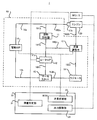
- FIG. 1 is a block diagram showing an example of the configuration of the hybrid vehicle 1 of the present embodiment.
- the hybrid vehicle 1 includes an axle 11, a wheel 12, an engine 20, an ECU 30, a motor generator MG1, a motor generator MG2, a transaxle 300, an inverter 400, a battery 500, and an SOC (State-of-Charge) sensor 510.
- an axle 11 a wheel 12
- an engine 20 an ECU 30, a motor generator MG1, a motor generator MG2, a transaxle 300, an inverter 400, a battery 500, and an SOC (State-of-Charge) sensor 510.
- the axle 11 is a transmission shaft for transmitting the power output from the engine 20 and the motor generator MG2 to the wheels.
- the wheel 12 is a means for transmitting the power transmitted through the axle 11 described later to the road surface.
- FIG. 1 shows an example in which the hybrid vehicle 1 includes one wheel 12 on each side, but actually, each vehicle has one wheel 12 on the front, rear, left, and right (that is, a total of four wheels 12 are provided). Are preferred).
- the ECU 30 is an electronic control unit configured to be able to control the entire operation of the hybrid vehicle 1.
- the ECU 30 includes a CPU (Central Processing Unit), a ROM (Read Only Memory), a RAM (Random Access Memory), and the like.
- the engine 20 is a gasoline engine or a diesel engine which is an example of an “internal combustion engine”, and functions as a main power source of the hybrid vehicle 1.
- the motor generator MG1 is an example of a “rotary electric machine”, and functions as a generator for charging the battery 500 or supplying electric power to the motor generator MG2. Furthermore, motor generator MG1 functions as an electric motor that assists the driving force of engine 20.
- the motor generator MG2 is an example of a “rotary electric machine” and functions as an electric motor that assists the power of the engine 20. Furthermore, motor generator MG2 functions as a generator for charging battery 500.
- each of the motor generator MG1 and the motor generator MG2 is, for example, a synchronous motor generator. Therefore, each of motor generator MG1 and motor generator MG2 includes a rotor having a plurality of permanent magnets on the outer peripheral surface, and a stator wound with a three-phase coil that forms a rotating magnetic field. However, at least one of motor generator MG1 and motor generator MG2 may be another type of motor generator.
- the transaxle 300 is a power transmission mechanism in which a transmission, a differential gear, and the like are integrated.
- the transaxle 300 particularly includes a power split mechanism 310.
- the power split mechanism 310 is a planetary gear mechanism including a sun gear, a planetary carrier, a pinion gear, and a ring gear (not shown).
- the rotation shaft of the sun gear on the inner periphery is connected to the motor generator MG1
- the rotation shaft of the ring gear on the outer periphery is connected to the motor generator MG2.
- the rotation shaft of the planetary carrier located between the sun gear and the ring gear is connected to the engine 20, and the rotation of the engine 20 is transmitted to the sun gear and the ring gear by the planetary carrier and further the pinion gear.
- the rotating shaft of the ring gear is connected to the axle 11 in the hybrid vehicle 1, and the driving force is transmitted to the wheels 12 through the axle 11.
- Inverter 400 converts DC power extracted from battery 500 into AC power and supplies it to motor generator MG1 and motor generator MG2, and also converts AC power generated by motor generator MG1 and motor generator MG2 into DC power.
- the battery 500 can be supplied.
- the inverter 400 may be configured as a part of a so-called PCU (Power Control Unit).
- Battery 500 is a rechargeable storage battery configured to be able to function as a power supply source related to power for operating motor generator MG1 and motor generator MG2.
- the battery 500 may be charged by receiving power from an external power source of the hybrid vehicle 1. That is, the hybrid vehicle 1 may be a so-called plug-in hybrid vehicle.
- the SOC sensor 510 is a sensor configured to be able to detect a remaining battery level that represents the state of charge of the battery 500.
- the SOC sensor 510 is electrically connected to the ECU 30, and the SOC value of the battery 500 detected by the SOC sensor 510 is always grasped by the ECU 30.
- FIG. 2 is a block diagram illustrating a configuration of the cooling device 10 included in the hybrid vehicle 1 of the present embodiment.
- the cooling device 10 included in the hybrid vehicle 1 of the present embodiment is a device that supplies cooling water to the engine 20.
- the cooling device 10 includes an exhaust heat recovery device 11, a heater core 12, a flow rate adjustment valve 13, a radiator 14, a thermostat 15, an electric WP (Water Pump: water pump) 16, a water temperature sensor 17a, and a water temperature sensor 17b. And.
- the cooling device 10 includes a cooling water passage 18a and a cooling water passage 18b, a cooling water passage 181a, a cooling water passage 181b and a cooling water passage 181c, a cooling water passage 182a, a cooling water passage 182b and a cooling water passage 182c, and a cooling water.
- a cooling water passage 18 including a passage 183a and a cooling water passage 183b is provided.
- the electric WP 16 is a pump that discharges cooling water having a desired flow rate.
- the cooling water discharged by the electric WP 16 flows into the cooling water passage 18a.
- the cooling water passage 18a branches into a cooling water passage 181a and a cooling water passage 182a.
- the cooling water passage 181 a is connected to the exhaust heat recovery device 11.
- a cooling water passage 181 b connected to the heater core 12 extends from the exhaust heat recovery device 11.
- a cooling water passage 181 c connected to the thermostat 15 extends from the heater core 12.
- a cooling water passage 18 b connected to the electric WP 16 extends from the thermostat 15. That is, the cooling water discharged from the electric WP 17 returns to the electric WP 17 by passing through the cooling water passage 18a, the cooling water passage 181a, the cooling water passage 181b, the cooling water passage 181c, and the cooling water passage 18b in this order.
- a bypass passage that does not pass through the engine 20 is formed from the cooling water passage 18a, the cooling water passage 181a, the cooling water passage 181b, the cooling water passage 181c, and the cooling water passage 18b.
- the bypass passage is a specific example of the “first passage” described above.
- the cooling water passage 182a is connected to the engine 20.
- a cooling water passage 182 b connected to the flow rate adjustment valve 13 extends from the engine 20.
- a cooling water passage 182 c connected to the heater core 12 extends from the flow rate adjustment valve 13. That is, the cooling water discharged from the electric WP 17 passes through the cooling water passage 18a, the cooling water passage 182a, the cooling water passage 182b, the cooling water passage 182c, the cooling water passage 181c, and the cooling water passage 18b in this order. Return to WP17.
- the cooling water passage 18a, the cooling water passage 182a, the cooling water passage 182b, the cooling water passage 182c, the cooling water passage 181c, and the cooling water passage 18b pass through the engine 20 (that is, do not bypass) while passing through the radiator 14.
- a main passage that does not (that is, bypasses) is formed.
- the main passage is a specific example of the “second passage” described above.
- a cooling water passage 183 a connected to the radiator 14 extends from the flow rate adjustment valve 13.
- a cooling water passage 183 b connected to the thermostat 15 extends from the radiator 14. That is, the cooling water discharged from the electric WP 17 passes through the cooling water passage 18a, the cooling water passage 182a, the cooling water passage 182b, the cooling water passage 183a, the cooling water passage 183b, and the cooling water passage 18b in this order. Return to WP17. That is, the cooling water passage 18a, the cooling water passage 182a, the cooling water passage 182b, the cooling water passage 183a, the cooling water passage 183b, and the cooling water passage 18b pass through the engine 20 (that is, do not bypass) and the radiator 14 also passes through. A sub-passage is formed (that is, not bypassed).
- the cooling water flows into the engine 20 from the cooling water passage 182a.
- the cooling water flowing into the engine 20 passes through the water jacket in the engine 20 and then flows out from the cooling water passage 182b.
- the water jacket is provided around a cylinder (not shown) in the engine 20.
- the cylinder exchanges heat with the cooling water passing through the water jacket. As a result, the engine is cooled.
- engine water temperature the water temperature of the cooling water passing through the engine 20 (hereinafter referred to as “engine water temperature” as appropriate) is appropriately measured by a water temperature sensor 17 b installed in the engine 20 or in the vicinity of the engine 20.
- the engine water temperature measured by the water temperature sensor 17b is output to the ECU 30.
- the exhaust heat recovery device 11 is provided on an exhaust passage (not shown) through which exhaust gas from the engine 20 passes.
- the cooling water passes inside the exhaust heat recovery device 11.
- the exhaust heat recovery unit 11 recovers exhaust heat by exchanging heat between the cooling water passing through the interior and the exhaust gas. That is, the exhaust heat recovery device 11 can heat the cooling water using the heat of the exhaust gas.
- the heater core 12 recovers heat of the cooling water by exchanging heat between the cooling water passing through the heater core 12 and the air. In other words, heat is input to the heater core 12 from the cooling water that passes through the interior of the heater core 12.
- the air heated by the heat recovered by the heater core 12 (in other words, the heat input to the heater core 12) is called a heater blower (not shown) for heating or the like (for example, heater, defroster, deice, etc.). The air is blown into the passenger compartment by the blower.
- the water temperature of the cooling water passing through the heater core 12 (hereinafter referred to as “heater water temperature” as appropriate) is appropriately measured by a water temperature sensor 17a installed in the heater core 12 or in the vicinity of the heater core 12.
- the heater water temperature measured by the water temperature sensor 17a is output to the ECU 30.
- the flow rate adjustment valve 13 is a valve (for example, FCV: Flow Control Valve) that can change the open / close state of the valve body under the control of the ECU 30. For example, when the flow rate adjustment valve 13 is closed, the inflow of cooling water from the cooling water passage 182b to the cooling water passage 182c and the inflow of cooling water from the cooling water passage 182b to the cooling water passage 183a are blocked. . In this case, the cooling water stays in the cooling water passage 182a, the cooling water passage 182b, the cooling water passage 182c, the cooling water passage 183a, and the cooling water passage 183b.
- FCV Flow Control Valve
- the flow rate adjustment valve 13 when the flow rate adjustment valve 13 is opened, the inflow of cooling water from the cooling water passage 182b to the cooling water passage 182c and the inflow of cooling water from the cooling water passage 182b to the cooling water passage 183a are permitted. Is done. In this case, the cooling water that has flowed out of the engine 20 into the cooling water passage 182b passes through the cooling water passage 182c and flows into the heater core 12, and also passes through the cooling water passage 183a and flows into the radiator 14. In addition, the flow rate adjusting valve 13 can adjust the opening degree of the valve body when the valve is opened under the control of the ECU 30.
- the flow rate adjusting valve 13 is a flow rate of cooling water flowing out from the flow rate adjusting valve 13 to the cooling water passage 182c (substantially, a flow rate of cooling water in the main passage) and from the flow rate adjusting valve 13 to the cooling water passage 183a. And the flow rate of cooling water flowing out (substantially, the flow rate of cooling water in the sub-passage) can be adjusted.
- the cooling water passing through the inside of the radiator 14 is cooled by outside air.
- cooling of the cooling water in the radiator 14 is promoted by the wind introduced by the rotation of the electric fan (not shown).
- the thermostat 15 includes a valve that opens and closes according to the temperature of the cooling water.
- the thermostat 15 is opened when the temperature of the cooling water is high (for example, equal to or higher than a predetermined temperature).
- the cooling water passage 183b and the cooling water passage 18b are connected via the thermostat 15.
- the cooling water passes through the radiator 14.
- the thermostat 15 is closed. In this case, the cooling water does not pass through the radiator 14. Thereby, since the temperature fall of a cooling water is suppressed, the overcool of the engine 20 is suppressed.
- the electric WP 16 includes an electric motor, and the cooling water is circulated in the cooling water passage 18 by driving the motor. Specifically, the electric WP 16 is supplied with electric power from a battery, and the rotation speed and the like are controlled by a control signal supplied from the ECU 30. Instead of the electric WP 16, a mechanical water pump that can operate regardless of the operation of the engine 20 and can be controlled by the ECU 30 may be used.
- the ECU 30 is a specific example of the “cooling water control device”, and controls the cooling device 10 (particularly, controls the flow rate and path of the cooling water in the cooling device 10).
- the ECU 30 includes a heat quantity determination unit 31 that is a specific example of “setting means”, and “first A flow rate adjustment unit 32, which is a specific example of “control unit” and “second control unit”, and an output adjustment unit 33, which is a specific example of “first control unit”.
- the detailed operations of the heat quantity determination unit 31, the flow rate adjustment unit 32, and the output adjustment unit 33 will be described in detail later (see FIG. 3).
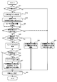
- FIG. 3 is a flowchart showing a control flow of the cooling device 10 realized by the ECU 30 of the present embodiment. Note that the operation shown in FIG. 3 is preferably an operation mainly performed during warming up of the engine 20 (that is, when warming up the engine 20 in the cold state).
- the heat quantity determination unit 31 determines whether or not there is a heater request (for example, a request for heating using heat input to the heater core 12 (in other words, heat recovered by the heater core 12)). Determination is made (step S11). For example, when the passenger of the vehicle 1 turns on a switch such as heating, the heat quantity determination unit 31 may determine that there is a heater request.
- a heater request for example, a request for heating using heat input to the heater core 12 (in other words, heat recovered by the heater core 12). Determination is made (step S11). For example, when the passenger of the vehicle 1 turns on a switch such as heating, the heat quantity determination unit 31 may determine that there is a heater request.
- step S11 when it is determined that there is no heater request (step S11: No), the flow rate adjustment unit 32 controls the flow rate adjustment valve 13 so that the flow rate adjustment valve 13 is closed. (Step S29). As a result, the cooling water circulates in the bypass passage, and the cooling water stays in the main passage and the sub passage. In addition, the flow rate adjusting unit 32 controls the electric WP 16 so as to set the flow rate of the cooling water discharged by the electric WP 16 to a minimum value (step S29). As a result, the flow rate of the cooling water circulating in the bypass passage is set to the minimum value.
- FIG. 4 is a block diagram showing how the cooling water circulates when the flow rate adjustment valve 13 is closed.
- cooling water flows from the cooling water passage 182b to the cooling water passage 182c and from the cooling water passage 182b to the cooling water passage 183a. Inflow is blocked. For this reason, the cooling water stays in the cooling water passage 182a, the cooling water passage 182b, and the cooling water passage 182c constituting the main passage. Similarly, the cooling water stays in the cooling water passage 183a and the cooling water passage 183b constituting the sub passage.
- cooling water circulates in the cooling water passage 18a, the cooling water passage 181a, the cooling water passage 181b, the cooling water passage 181c, and the cooling water passage 18b constituting the bypass passage.
- the arrow in FIG. 4 has shown the direction through which cooling water flows.
- step S11 when it is determined that there is a heater request as a result of the determination in step S11 (step S11: Yes), after the elapse of a predetermined time for heating specified by the heater request, etc. It is estimated that the heater blower switch is turned on. As a result, it is presumed that supply of air warmed by the heat input to the heater core 12 into the vehicle interior is started. In this embodiment, after it is determined that there is a heater request (that is, after a switch such as heating is turned on), the supply of warmed air is started (that is, the heater blower is turned on).
- the cooling device 10 is controlled so that the amount of heat input to the heater core (hereinafter referred to as “heater core input heat amount”) is positively adjusted.
- the amount of heat input to the heater core is equal to the amount of heat required by the heater core (that is, The amount of heat input to the heater core is positively adjusted so as to coincide with the amount of heat necessary for heating or the like having a desired intensity specified by the heater request, and hereinafter referred to as “heater core required heat amount”. That is, in the present embodiment, the heater core input heat amount is positively adjusted before the air blowing start time.
- a mode for adjusting the amount of heat input to the heater core at a time prior to the air blowing start time will be described in detail.
- the heat amount determination unit 31 sets a target heat amount line (step S12).
- the target heat quantity line defines the target value of the heat input to the heater core during the period from the timing (for example, the current time) when the target heat quantity line is set to the blow start time, in chronological order.
- the target heat amount line is set so that the heater core input heat amount coincides with the heater core required heat amount at the time when the air blowing start time is reached (that is, the heater core required heat amount is satisfied by the heater core input heat amount).
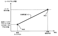
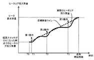
- FIG. 5 is a graph showing a target heat amount line.
- the target heat amount line may be a graph that can define the relationship between time and the amount of heat input to the heater core.
- the horizontal axis indicates time
- the vertical axis indicates the amount of heat input to the heater core.
- the starting point of the target heat amount line is preferably a point corresponding to the amount of heat input to the heater core at the present time (for example, when the heating switch is turned on or when the target heat amount line is set).
- the current amount of heat input to the heater core is calculated, for example, from the current heater water temperature and the amount of cooling water passing through the heater core 12 at the current time.
- the current heater water temperature is output from the water temperature sensor 17a, for example.
- the amount of cooling water currently passing through the heater core 12 is easily calculated from the control amount of the electric WP 16, for example. Therefore, the heat quantity determination unit 31 can set the start point of the target heat quantity line relatively easily.
- the starting point of the target heat amount line may be a point other than the point corresponding to the current heat input to the heater core.
- the starting point of the target line may be a point corresponding to the amount of heat input to the heater core of the internal combustion engine in the cold state (that is, the amount of heat input to the core corresponding to the soak temperature).
- the target heat amount line has an end point corresponding to the heater core required heat amount at the start of air blowing.
- the heater core required heat amount is easily calculated from, for example, the operation content of a switch that specifies the intensity of heating or the like by the passenger.
- the blow start time is set in advance according to the specifications of the hybrid vehicle 1, for example. Therefore, the heat quantity determination unit 31 can set the end point of the target heat quantity line relatively easily.
- the heat amount determination unit 31 sets a continuous line from the start point to the end point.
- the heat quantity determination unit 31 can suitably set a target heat quantity line as a continuous line.
- the target heat amount line is preferably a line that increases continuously or stepwise from the start point to the end point.
- the target heat amount line may be a line that increases at a fixed increase rate from the start point toward the end point (that is, a line that increases at a constant increase rate until the blow start time).
- the target heat amount line may be a line that increases at an increase rate that appropriately varies from the start point to the end point (that is, a line that increases at a different increase rate for each time).
- the target heat amount line is a line that continuously increases at a fixed increase rate from the start point to the end point (that is, a line that can be expressed by a linear function).
- the target heat amount line increases in any manner from the start point to the end point. May be.
- the target heat amount line may be a line that decreases at some time.
- the target heat amount line may be a line in which a state in which the heater core input heat amount and the heater core required heat amount coincide with each other is realized for the first time in the blowing start instruction.
- the target heat amount line may be a line that is realized at a time point before the air blow start time when the heater core input heat amount matches the heater core required heat amount.
- the target heat amount line may include a line that defines a target value at a time before the above-described start point (that is, a line extending to the left side from the start point in FIG. 5).
- the target heat amount line may include a line that defines a target value at a time later than the above-described end point (that is, a line extending to the right side of the end point in FIG. 5).
- the target heat amount line is shown in the form of a graph.
- the target heat amount line may be any type of information as long as the relationship between the time and the heater core input heat amount can be defined continuously or discretely. Examples of such information include a table, a map, a numerical sequence, a function, a database, and the like.
- the target heat amount line is shown as a continuous line.
- the target heat quantity line may be a set of discrete points on the continuous line.
- the target heat amount line is a set of discrete points (that is, a set of target values associated with a specific time) that can approximate a virtual line from the start point described above to the end point described above. There may be.
- the cooling device 10 is controlled so that the amount of heat input to the heater core follows the target heat amount line as time passes. That is, the cooling device 10 is controlled so that the actual input heat amount of the heater core at each time during the period until the blow start time coincides with the target value at each time indicated by the target heat amount line. In other words, the cooling device 10 is set so that the actual amount of heat input to the heater core at each time during the period until the blow start time satisfies (that is, exceeds) the target value at each time indicated by the target heat amount line. Is controlled. In addition, it is preferable that the operation
- the operation described below (that is, the operation from step S13 to step S24) is preferably performed repeatedly until the air blowing start time is reached (step S20). Further, the operation described below (that is, the operation from step S13 to step S24) may be performed regularly, periodically, or randomly between the target heat amount line setting timing and the air blowing start timing.
- the heat amount determination unit 31 calculates the heater core input heat amount (step S21). As described above, it is easily calculated from the heater water temperature and the amount of cooling water passing through the heater core 12. Alternatively, the heat quantity determination unit 31 may estimate or predict the heater core input heat quantity based on the output of the engine 20, the heat quantity recoverable by the exhaust heat recovery device 11, the heater water temperature, or the like.
- the heat quantity determination unit 31 determines whether or not the heater core input heat quantity can follow the target heat quantity line (step S22). At this time, the heat amount determination unit 31 determines whether or not the heater core input heat amount at the time of performing the determination satisfies or exceeds the target value corresponding to the time of the determination specified by the target heat amount line. You may judge. When the heater core input heat amount satisfies or exceeds the target value, it may be determined that the heater core input heat amount can follow the target heat amount line. Alternatively, the heat amount determination unit 31 determines whether the deviation rate between the heater core input heat amount at the time of the determination and the target value corresponding to the time of the determination specified by the target heat amount line is less than a predetermined value. It may be determined whether or not. When the deviation rate between the heater core input heat amount and the target value is less than a predetermined value, it may be determined that the heater core input heat amount can follow the target heat amount line.
- step S22 the heat quantity determination unit 31 has a minimum flow rate of the cooling water passing through the heater core 12, and the flow rate adjustment valve 13 is closed (that is, the cooling water is circulated in the bypass passage).
- the heat input to the heater core can be made to follow the target heat amount line while maintaining the state in which the cooling water is retained in the main passage and the sub passage.
- the heat quantity determination unit 31 uses the amount of heat that can be recovered by the exhaust heat recovery device 11 in a state where the flow rate of the cooling water passing through the heater core 12 is the minimum value and the flow rate adjustment valve 13 is closed. It can also be said that it is determined whether or not the heater core input heat amount can follow the target heat amount line.
- the amount of heat that can be recovered by the exhaust heat recovery unit 11 can be calculated relatively easily from the flow rate of the cooling water passing through the exhaust heat recovery unit 11, the temperature of the exhaust gas, and the like.
- step S22 when it is determined that the amount of heat input to the heater core can follow the target heat amount line (step S22: Yes), the flow rate adjustment unit 32 closes the flow rate adjustment valve 13.
- step S29 the flow regulating valve 13 is controlled.
- the cooling water circulates in the bypass passage, and the cooling water stays in the main passage and the sub passage.
- the flow rate adjusting unit 32 controls the electric WP 16 so as to set the flow rate of the cooling water discharged by the electric WP 16 to a minimum value (step S29). As a result, the flow rate of the cooling water circulating in the bypass passage is set to the minimum value.
- step S22 when it is determined that the heater core input heat amount cannot follow the target heat amount line (step S22: No), in this embodiment, the heater core input heat amount is set to the target heat amount line. A positive action is taken to follow.
- the operation for causing the heater core input heat amount to follow the target heat amount line is as follows: (i) Cooling water passing through the exhaust heat recovery device 11 (that is, circulating through the bypass passage) with the flow rate adjustment valve 13 closed.
- the amount of heat that can be recovered by the exhaust heat recovery device 11 varies.
- the heater core input heat amount can follow the target heat amount line.
- the temperature of the exhaust gas exhausted from the engine 20 varies.
- the amount of heat that can be recovered by the exhaust heat recovery device 11 varies.
- the heater core input heat amount can follow the target heat amount line.
- the heater core 12 receives heat from not only the cooling water that has passed through the exhaust heat recovery device 11 but also from the cooling water that has passed through the engine 20. As a result, since the heater core input heat amount varies, the heater core input heat amount can follow the target heat amount line.
- the heat quantity determination unit 31 first increases the flow rate of the cooling water passing through the heater core 12 from the minimum value (further, the flow rate adjustment valve 13 is In a state where the valve is closed), it is determined whether or not the heater core input heat amount can follow the target heat amount line (step S23). In other words, the heat quantity determination unit 31 adjusts the flow rate of the cooling water passing through the heater core 12 (that is, adjusts the flow rate of the cooling water discharged by the electric WP 16), thereby causing the heater core input heat amount to follow the target heat amount line. It is determined whether or not it is possible (step S23). That is, the heat amount determination unit 31 determines whether or not the heater core input heat amount can follow the target heat amount line by performing the first operation (step S23).
- the heat amount determination unit 31 can cause the heater core input heat amount to follow the target heat amount line while minimizing the deterioration of fuel consumption (in other words, suppressing it to the minimum). It is preferable to determine whether or not. For example, it is preferable that the calorific value determination unit 31 selects an operation among the above-described three types of operations in which the deterioration of fuel consumption is minimized (preferably, the deterioration of fuel consumption is minimized or does not deteriorate).
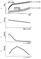
- FIG. 6 shows the amount of heat that can be recovered from the cooling water that passes through the exhaust heat recovery unit 11 (that is, cooling water that circulates in the bypass passage) and the cooling water that passes through the engine 20 (that is, cooling water that circulates in the main passage).
- the amount of heat recoverable from the cooling water passing through the exhaust heat recovery unit 11 also increases. Further, if the output of the engine 20 increases as shown by the arrow in FIG. 6A, the amount of heat that can be recovered from the cooling water (especially the cooling water having the same flow rate) passing through the exhaust heat recovery unit 11 is also To increase.
- the amount of heat that can be recovered from the cooling water passing through the engine 20 also increases. Further, as the output of the engine 20 increases as shown by the arrow in FIG. 6A, the amount of heat that can be recovered from the cooling water passing through the engine 20 (particularly, cooling water having the same flow rate) also increases.
- the heat quantity determination unit 31 sets the flow rate of the cooling water passing through the exhaust heat recovery device 11, the flow rate of the cooling water passing through the engine 20, and the output of the engine 20 as appropriate, so that the heat input to the heater core is relatively easy. Can be recognized.
- an increase in the flow rate of the cooling water passing through the exhaust heat recovery device 11 is typically realized by an increase in the flow rate of the cooling water discharged by the electric WP 16.
- the power consumption of the electric WP 16 increases.
- An increase in power consumption of the electric WP 16 leads to a deterioration in fuel consumption of the vehicle 1. That is, as shown in FIG. 6B, the fuel consumption of the vehicle 1 is deteriorated as the flow rate of the cooling water discharged from the electric WP 16 increases.
- the engine 20 is prevented from warming up by allowing the coolant to pass through the engine 20 as well.
- warming up of the engine 20 is prevented as the flow rate of the cooling water passing through the engine 20 increases.
- the obstruction of warming up of the engine 20 leads to deterioration of the fuel consumption of the vehicle 1. That is, as shown in FIG. 6C, the fuel consumption of the vehicle 1 is deteriorated as the flow rate of the cooling water passing through the engine 20 is increased.
- an increase in the output of the engine 20 may lead to a deterioration in the fuel consumption of the vehicle 1.
- the increase (that is, adjustment) of the output of the engine 20 performed in the present embodiment is performed mainly for the purpose of causing the heater core input heat amount to follow the target heat amount line.
- the operating point of the engine 20 may deviate from the optimum fuel consumption output point by adjusting the output (however, the adjustment of the output of the engine 20 causes the operating point of the engine 20 to deviate from the optimum fuel consumption line or Preferably none at all).
- the more the output of the engine 20 deviates from the output corresponding to the optimal fuel efficiency line the output corresponding to the peak of the fuel efficiency effect in FIG. 6 (d)
- the vehicle The fuel consumption of 1 can deteriorate.
- the calorific value determination unit 31 has a fuel consumption deterioration caused by adjustment of the flow rate of the cooling water discharged from the electric WP 16 among the three types of operations described above, and a fuel consumption rate caused by an increase in the flow rate of the cooling water passing through the engine 20. And the deterioration of the fuel consumption due to the adjustment of the output of the engine 20 is reduced as much as possible (preferably, the deterioration of the fuel consumption is minimized or the fuel consumption is not deteriorated). It is preferable to select.
- the calorific value determination unit 31 displays the graphs (or functions, mappings, mathematical expressions, and other various information such as tables) shown in FIG. 6 (a) to FIG. 6 (d). You may refer to
- the heater core input heat amount can be made to follow the target heat amount line by any of the operation and (iii) at least two of the third operations in which the coolant is allowed to pass through the engine 20 as well.
- the heater core input heat amount can follow the target heat amount line by the first operation and the third operation, respectively.
- the exhaust heat recovery device when the first operation for increasing the flow rate of the cooling water passing through the exhaust heat recovery device 11 with the flow rate adjustment valve 13 closed is performed.
- the flow rate of the cooling water passing through 11 (that is, the flow rate capable of causing the heater core input heat amount to follow the target heat amount line) is derived.
- the degree of deterioration of fuel consumption due to the first operation for increasing the flow rate of the cooling water passing through the exhaust heat recovery device 11 with the flow rate adjustment valve 13 closed is derived. It is.
- the cooling water passing through the exhaust heat recovery device 11 when the third operation for passing the cooling water not only to the exhaust heat recovery device 11 but also to the engine 20 is performed.
- the flow rate and the flow rate of the cooling water passing through the engine 20 are derived. As a result, from the graphs shown in FIGS.
- the degree of deterioration in fuel consumption due to the third operation of passing the coolant through not only the exhaust heat recovery device 11 but also the engine 20 is derived.
- the calorific value determination unit 31 can select an operation in which the deterioration of the fuel consumption is minimized (preferably, the deterioration of the fuel consumption is minimized or the fuel consumption is not deteriorated) by comparing the degree of deterioration of the both fuel consumptions. .
- an operation in which the deterioration of fuel consumption is minimized preferably, the deterioration of fuel consumption is minimized or does not deteriorate
- Step S23 when it is determined as a result of the determination in step S23 that the amount of heat input to the heater core can be made to follow the target heat amount line with the flow rate of the cooling water passing through the heater core 12 increased from the minimum value. (Step S23: Yes), the flow rate adjustment unit 32 controls the flow rate adjustment valve 13 so that the flow rate adjustment valve 13 is closed (Step S28).
- Step S28 the deterioration of fuel consumption resulting from performing the first operation of increasing the flow rate of the cooling water passing through the exhaust heat recovery device 11 with the flow rate adjustment valve 13 closed is caused by the engine deterioration.
- the deterioration in fuel consumption resulting from performing the second operation for adjusting the output of 20 and the deterioration in fuel consumption resulting from performing the third operation for opening the flow rate adjusting valve 13 are smaller.
- the cooling water circulates in the bypass passage, and the cooling water stays in the main passage and the sub passage.
- the flow rate adjusting unit 32 controls the electric WP 16 so as to increase (in other words, adjust) the flow rate of the cooling water discharged by the electric WP 16 from the minimum value (step S28). At this time, it is preferable that the flow rate adjusting unit 32 increase the flow rate of the cooling water so that the heater core input heat amount follows the target heat amount line. Therefore, the flow rate adjusting unit 32 preferably determines the flow rate of the cooling water discharged by the electric WP 16 according to the target heat amount line set in step S12 and the heater core input heat amount calculated in step S21.
- step S28 when the operation of step S28 is performed, the flow rate adjustment valve 13 is closed. Therefore, the flow rate of the cooling water discharged by the electric WP 16 is substantially the same as the flow rate of the cooling water circulating in the bypass passage. Therefore, it can be said that the flow rate adjusting unit 32 determines the flow rate of the cooling water circulating in the bypass passage according to the target heat quantity line.
- FIG. 7 is a graph showing the flow rate of cooling water to be discharged by the electric WP 16 (in other words, the flow rate of cooling water to be circulated through the bypass passage), which is determined so as to follow the heat input amount of the heater core to the target heat amount line. .
- the amount of heat corresponding to the deviation between the heater core input heat amount and the target heat amount line (specifically, the target value indicated by the target heat amount line ⁇ heater core input heat amount) is set to the electric WP16. May be compensated by an increase (in other words, adjustment) in the flow rate of the cooling water to be discharged. Therefore, as shown in FIG. 7, the larger the deviation between the heater core input heat amount and the target heat amount line, the more the flow rate of the cooling water to be discharged by the electric WP 16 increases, the heater core input heat amount follows the target heat amount line. It is assumed that it can be made. Accordingly, the flow rate adjusting unit 32 determines the flow rate of the cooling water discharged by the electric WP 16 by referring to the graph (or other various information such as a function, mapping, mathematical expression, and table) shown in FIG. It is preferable to do.
- the amount of heat input to the heater core follows the target heat amount line.
- the third operation using not only the heat of the cooling water flowing into the heater core 12 via the exhaust heat recovery device 11 but also the heat of the cooling water flowing into the heater core 12 via the engine 20 is performed. By performing, the heater core input heat amount is made to follow the target heat amount line.
- the relationship between the deviation between the heater core input heat amount and the target heat amount line and the flow rate of the cooling water also changes. For example, when the heater water temperature increases, the amount of heat that can be recovered from the same amount of cooling water increases. That is, when the heater water temperature is increased, the flow rate of the cooling water necessary for causing the same heater core input heat amount to follow the same target heat amount line decreases. As a result, when the heater water temperature increases, the relationship between the deviation between the heater core input heat amount and the target heat amount line and the flow rate of the cooling water relatively shifts to the right as shown by the one-dot chain line in FIG.
- the heater water temperature decreases, the amount of heat that can be recovered from the cooling water having the same flow rate decreases. That is, when the heater water temperature decreases, the flow rate of the cooling water necessary for causing the same heater core input heat amount to follow the same target heat amount line increases. As a result, when the heater water temperature decreases, the relationship between the deviation between the heater core input heat amount and the target heat amount line and the flow rate of the cooling water shifts relatively to the left as shown by the dotted line in FIG.
- both the second operation for adjusting the output of the engine 20 and the third operation for allowing the coolant to pass through the engine 20 substantially correspond to the operation for adjusting the heater water temperature. Therefore, it can be said that both the second operation and the third operation make the heater core input heat amount follow the target heat amount line using the relationship indicated by the dotted line or the alternate long and short dash line in FIG.
- step S23 it is determined that the amount of heat input to the heater core cannot follow the target heat amount line with the flow rate of the cooling water passing through the heater core 12 increased from the minimum value. If this is the case (step S23: No), the output adjustment unit 33 performs a second operation for adjusting the output of the engine 20 so that the heater core input heat amount follows the target heat amount line.
- step S23 even if it is determined that the heater core input heat amount can be made to follow the target heat amount line in a state where the flow rate of the cooling water passing through the heater core 12 is increased from the minimum value, The deterioration of fuel efficiency resulting from the first operation for increasing the flow rate of the cooling water passing through the exhaust heat recovery device 11 with the flow rate adjustment valve 13 closed results from the second operation for adjusting the output of the engine 20.
- the output adjustment unit 33 may perform a second operation of adjusting the output of the engine 20 in order to cause the heater core input heat amount to follow the target heat amount line.
- the flow rate adjusting unit 32 sets the flow rate of the cooling water that passes through the cooling water passage 181a, the cooling water passage 182a, and the cooling water passage 182c constituting the bypass passage (that is, substantially Adjusts the opening of the flow rate adjusting valve 13 and the flow rate of the cooling water discharged by the electric WP 16 so as not to reduce the flow rate of the cooling water passing through the exhaust heat recovery device 11.
- the flow rate adjusting unit 32 flows through the cooling water passage 181a, the cooling water passage 182a, and the cooling water passage 182c constituting the bypass passage (that is, substantially passes through the exhaust heat recovery device 11). It is preferable to adjust the opening of the flow rate adjusting valve 13 and the flow rate of the cooling water discharged by the electric WP 16 so that the flow rate of the cooling water is maintained at the maximum value.
- the output adjustment unit 33 is Increase the output of the engine 20.
- the temperature of the exhaust gas exhausted from the engine 20 increases.
- the amount of heat that can be recovered by the exhaust heat recovery device 11 increases. Accordingly, even if the heater core input heat amount cannot follow the target heat amount line only by the first operation, the heater core input heat amount can follow the target heat amount line.
- the amount of heat corresponding to the deviation between the heater core input heat amount and the target heat amount line (specifically, the target value indicated by the target heat amount line minus the heater core input heat amount) is This may be compensated for by an increase in the temperature of the exhaust gas due to the increase in the output of. Therefore, it is assumed that if the output of the engine 20 is increased as the deviation between the heater core input heat amount and the target heat amount line increases, the heater core input heat amount can follow the target heat amount line.
- the adjustment of the output of the engine 20 may give the passenger a sense of incongruity (for example, deterioration in ride comfort). For this reason, if it considers from a viewpoint of relieving or eliminating the discomfort given to a passenger, the output adjustment part 33 may suppress the increase amount (or adjustment amount) of the output of the engine 20 to the minimum.
- the output adjustment unit 33 considers the relationship between the amount of increase in the output of the engine 20 and the change in riding comfort (for example, presence or absence of vibration, magnitude of vibration amount, etc.) due to the increase in output of the engine 20.
- the output of the engine 20 may be increased by an increase amount such that the influence on the ride comfort of the passenger falls within an allowable range. As a result, the uncomfortable feeling given to the occupant is alleviated or eliminated as compared with an aspect in which the increase in the output of the engine 20 is not minimized.
- the output adjustment unit 33 continues to perform an operation of increasing (or adjusting) the output of the engine 20. It is preferable to fix the increase amount (or adjustment amount) of the output of the engine 20. That is, it is preferable that the output adjustment unit 33 does not change the increase amount of the output of the engine 20 while continuing the operation of increasing the output of the engine 20. As a result, the uncomfortable feeling given to the occupant is alleviated or eliminated as compared with the aspect in which the increase amount of the output of the engine 20 is changed.
- the heater core input heat amount may not follow the target heat amount line only by the second operation of adjusting the output of the engine 20.
- the engine 20 performs the third operation of passing the cooling water, thereby causing the heater core input heat amount to follow the target heat amount line.
- the output adjustment amount of the engine 20 may be determined according to the travel mode desired by the passenger. For example, when the passenger desires a travel mode that prioritizes ride comfort (for example, NV (Noise Vibration) characteristics), the output adjustment unit 33 may minimize the adjustment amount of the output of the engine 20. Good. Similarly, when the passenger desires a travel mode in which ride comfort is given priority, the output adjustment unit 33 may fix the adjustment amount of the output of the engine 30.
- NV Noise Vibration
- the output adjustment unit 33 may positively adjust the output of the engine 20. In other words, the output adjustment unit 33 may increase the output of the engine 20 by an increase necessary for suitably charging the battery 500 instead of minimizing the adjustment amount of the output of the engine 20. .
- the output adjustment unit 33 is a ratio between the driving force shared by the engine 20 and the driving force shared by at least one of the motor generators MG ⁇ b> 1 and MG ⁇ b> 2. It is preferable to adjust the output of the engine 20 while appropriately adjusting the output. Specifically, the output adjustment unit 33 preferably adjusts the output of the engine 20 without affecting the travel of the hybrid vehicle 1.
- FIG. 8 is an operation alignment chart showing respective outputs (that is, driving force sharing ratios) of engine 20 and motor generators MG1 and MG2.
- the output adjustment unit 33 adjusts the rotation speed of the engine 20 and the rotation speed of the motor generator MG1 while maintaining the rotation speed of the motor generator MG2. As a result, the output adjustment unit 33 can adjust the output of the engine 20 without affecting the travel of the hybrid vehicle 1.
- the flow rate adjustment unit 32 adjusts the flow rate of the cooling water discharged by the electric WP 16 and the output adjustment unit 33 adjusts the output of the engine 20 so that the deterioration of the fuel consumption is minimized (preferably the smallest). May be.
- the heat quantity determination unit 31 determines whether or not the heater core input heat quantity can follow the target heat quantity line (that is, the heater core input heat quantity falls below the target heat quantity line). Whether or not there is) is determined (step S25).
- step S25 As a result of the determination in step S25, as a result of adjusting the output of the engine 20, if it is determined that the heater core input heat amount can follow the target heat amount line (step S25: Yes), the ECU 30 performs steps from step S21 to step S21. A series of operations up to S29 is once ended. In this case, it is preferable that the ECU 30 repeats a series of operations from step S21 to step S29 at a desired timing until the air blow start time is reached.
- step S25 when it is determined that the heat input to the heater core cannot be made to follow the target heat amount line even if the output of the engine 20 is adjusted (step S25: No), the flow rate adjustment unit 32. Performs the third operation of allowing the coolant to pass through not only the exhaust heat recovery device 11 but also the engine 20. Alternatively, even if it is determined as a result of the determination in step S25 that the heater core input heat amount can be made to follow the target heat amount line by adjusting the output of the engine 20, the output 20 of the engine 20 is adjusted.
- the output adjustment unit 33 of the engine 20 is a third operation for allowing the flow rate adjusting unit 32 to pass the cooling water not only to the exhaust heat recovery device 11 but also to the engine 20. May be performed.
- the heat quantity determination unit 31 acquires the engine water temperature (that is, the water temperature of the cooling water passing through the engine 20) by referring to the measurement result of the water temperature sensor 17b (step S26).
- the flow rate adjustment unit 32 controls the flow rate adjustment valve 13 so that the flow rate adjustment valve 13 is opened (step S27).
- the cooling water circulates in the bypass passage and the cooling water circulates in the main passage.
- FIG. 9 is a block diagram showing how the cooling water circulates when the flow rate adjustment valve 13 is opened.
- FIG. 9 shows a state where the thermostat 15 is closed (that is, a state where the cooling water stays in the cooling water passage 183a and the cooling water passage 183b constituting the sub passage).
- the cooling water also circulates in the cooling water passage 18a, the cooling water passage 181a, the cooling water passage 181b, the cooling water passage 181c, and the cooling water passage 18b constituting the bypass passage.
- the arrow in FIG. 9 has shown the direction through which cooling water flows.
- the flow rate adjusting unit 32 controls the flow rate adjusting valve 13 so as to adjust the opening degree of the valve body of the flow rate adjusting valve 13 (step S27). That is, the flow rate adjusting unit 32 adjusts the flow rate of the cooling water circulating in the main passage (in other words, the flow rate of the cooling water passing through the engine 20) by adjusting the opening of the valve body of the flow rate adjusting valve 13. To do.
- the flow rate adjusting unit 32 controls the electric WP 16 so as to adjust the flow rate of the cooling water discharged by the electric WP 16 (step S27).
- the flow rate adjusting unit 32 adjusts the flow rate of the cooling water discharged by the electric WP 16 to thereby flow the cooling water circulating in the bypass passage (in other words, the flow rate of the cooling water passing through the exhaust heat recovery device 11). And the flow rate of the cooling water circulating in the main passage (in other words, the flow rate of the cooling water passing through the engine 20) is adjusted.
- the flow rate adjusting unit 32 passes the cooling water passage 181a, the cooling water passage 182a, and the cooling water passage 182c constituting the bypass passage (ie, substantially passes through the exhaust heat recovery device 11).
- the flow rate of the cooling water discharged by the electric WP 16 and the opening of the flow rate adjusting valve 13 are adjusted so as not to reduce the flow rate of the cooling water to be discharged).
- the flow rate adjusting unit 32 flows through the cooling water passage 181a, the cooling water passage 182a, and the cooling water passage 182c constituting the bypass passage (that is, substantially passes through the exhaust heat recovery device 11). It is preferable to adjust the opening of the valve body of the flow rate adjusting valve 13 and the flow rate of the cooling water discharged by the electric WP 16 so that the flow rate of the cooling water is maintained at the maximum value.
- the flow rate adjustment unit 32 adjusts the opening of the flow rate adjustment valve 13 and the flow rate of the cooling water discharged by the electric WP 16 so that the heat input to the heater core follows the target heat amount line. Therefore, the flow rate adjusting unit 32 sets the opening of the flow rate adjusting valve 13 and the flow rate of the cooling water discharged from the electric WP 16 to the target heat amount line set in step S12, the heater core input heat amount calculated in step S21, and step S24. It is preferable to determine according to the adjustment amount of the output of the engine 20 adjusted in step S1 and the engine water temperature acquired in step S26.
- the output adjustment unit 33 cancels (that is, stops) the adjustment of the output of the engine 20 performed in step S24. Also good. Alternatively, the output adjustment unit 33 may continue to adjust the output of the engine 20 performed in step S24 as it is. When the output adjustment unit 33 continues to adjust the output of the engine 20 as it is, the output adjustment unit 33 calculates the adjustment amount of the output of the engine 20 in the target heat amount line set in step S12, step S21.
- the amount of heat input to the heater core, the adjustment amount of the output of the engine 20 adjusted in step S24, the engine water temperature acquired in step S26, the opening degree of the flow rate adjusting valve 13 determined in step S27, and the cooling water discharged by the electric WP 16 It is preferable to determine according to the flow rate.
- the flow rate of the cooling water passing through the exhaust heat recovery device 11 is maintained at the maximum value. That is, the amount of heat input to the heater core 12 from the cooling water flowing into the heater core 12 via the exhaust heat recovery device 11 is maintained at the maximum value. For this reason, the amount of heat input to the heater core 12 from the cooling water flowing into the heater core 12 via the engine 20 in order to make the amount of heat input to the heater core follow the target heat amount line is minimized. That is, the flow rate of the cooling water passing through the engine 20 is minimized.
- the flow rate adjusting unit 32 preferably adjusts the opening degree of the flow rate adjusting valve 13 and the flow rate of the cooling water discharged by the electric WP 16.
- the flow rate of the cooling water flowing into the heater core 12 via the engine 20 exceeds a predetermined upper limit value determined from the viewpoint of minimizing deterioration in fuel consumption due to an increase in the flow rate of cooling water passing through the engine 20. Preferably not.
- the flow rate adjusting unit 32 is caused by deterioration in fuel consumption due to adjustment of the flow rate of cooling water discharged by the electric WP 16 and increase in the flow rate of cooling water circulating in the main passage (that is, cooling water passing through the engine 20).
- the degree of opening of the valve body of the flow rate adjusting valve 13 and the flow rate of the cooling water discharged by the electric WP 16 are set so that the deterioration of the fuel consumption as a whole considering both the deterioration of the fuel consumption is minimized (preferably the smallest). May be adjusted.
- the third operation of allowing the coolant to pass through the engine 20 is also performed.
- the adjustment of the output of the engine 20 may give a sense of discomfort to the passenger. Accordingly, even if the heater core input heat amount can be made to follow the target heat amount line by adjusting the output of the engine 20, it is not desired to give the passenger an uncomfortable feeling by adjusting the output of the engine 20
- a third operation for allowing the coolant to pass through the engine 20 may also be performed.
- the cooling water is passed through the engine 20 even if the cooling water is passed through the engine 20.
- the impact of fuel consumption deterioration due to passage is reduced. Therefore, even if the heat input to the heater core can be made to follow the target heat quantity line by adjusting the output of the engine 20, the output of the engine 20 is adjusted if the engine 20 has been warmed up to some extent.
- the engine 20 may perform a third operation that allows the coolant to pass therethrough.
- FIG. 10 is a graph showing a specific example of the operation for causing the heater core input heat amount to follow the target heat amount line.
- a target heat amount line (see the dotted line in FIG. 10) is set from the point corresponding to the amount of heat input to the heater core at the time T0 to the point corresponding to the heater required heat amount at the air blow start timing.
- the flow rate of the cooling water passing through the heater core 12 is the minimum value and the flow rate adjusting valve 13 is kept closed, and the heat input amount of the heater core follows the target heat amount line.
- step S22 of FIG. 3: No if the flow rate of the cooling water passing through the heater core 12 is further increased from the minimum value, it is determined that the heater core input heat amount can be made to follow the target heat amount line.
- step S28 in FIG. 3 a first operation for adjusting the flow rate of the cooling water passing through the exhaust heat recovery device 11 with the flow rate adjustment valve 13 closed is performed (step S28 in FIG. 3).
- the amount of heat input to the heater core increases by an amount corresponding to the adjustment amount of the flow rate of the cooling water passing through the exhaust heat recovery unit 11. That is, the amount of heat input to the heater core is adjusted so as to follow the target line.
- step S23 in FIG. 3 a second operation for adjusting the output of the engine 20 is performed (step S24 in FIG. 3).
- step S24 in FIG. 3 the amount of heat input to the heater core increases by an amount corresponding to the adjustment amount of the output of the engine 20. That is, the amount of heat input to the heater core is adjusted so as to follow the target line.
- step S25 in FIG. 3: No the third operation for allowing the coolant to pass through not only the exhaust heat recovery device 11 but also the engine 20 is performed (step S27 in FIG. 3).
- step S27 in FIG. 3 the amount of heat input to the heater core increases by an amount corresponding to the flow rate of the cooling water passing through the engine 20. That is, the amount of heat input to the heater core is adjusted so as to follow the target line.
- the flow rate adjustment valve 13 is closed when there is no heater request.
- the cooling water circulates in the bypass passage, and the cooling water stays in the main passage and the sub passage.
- the cooling water stays in the water jacket of the engine 20 as compared with the mode in which the cooling water circulates in at least one of the main passage and the sub passage (that is, the cooling water passes through the water jacket of the engine 20). Heating is promoted (in other words, cooling of the cooling water is suppressed). As a result, warming up of the engine 20 is promoted. Therefore, the deterioration of fuel consumption due to the passage of cooling water through the engine 20 is suitably suppressed.
- the flow rate adjustment valve 13 is closed when the heater core input heat quantity can be made to follow the target heat quantity line in a state where there is a heater request and the flow rate of the cooling water becomes the minimum value.
- the cooling water circulates in the bypass passage, and the cooling water stays in the main passage and the sub passage. Therefore, the deterioration of fuel consumption due to the passage of cooling water through the engine 20 is suitably suppressed.
- heating at a desired intensity according to the heater request for example, the heater
- defroster or deice is preferably performed.
- the amount of heat input to the heater core can follow the target heat amount line.
- the flow rate adjustment valve 13 is closed.
- the cooling water circulates in the bypass passage, and the cooling water stays in the main passage and the sub passage. Therefore, the deterioration of fuel consumption due to the passage of cooling water through the engine 20 is suitably suppressed.
- heating at a desired intensity according to the heater request for example, the heater
- defroster or deice is preferably performed.
- the flow rate adjustment valve 13 is also closed when there is a heater request and the heater core input heat amount can be made to follow the target heat amount line by adjusting the output of the engine 20 (that is, corresponding to the second operation). .
- the cooling water circulates in the bypass passage, and the cooling water stays in the main passage and the sub passage. Therefore, the deterioration of fuel consumption due to the passage of cooling water through the engine 20 is suitably suppressed.
- heating at a desired intensity according to the heater request for example, the heater
- defroster or deice is preferably performed.
- the flow rate adjustment valve 13 is opened (that is, the cooling water flows into the engine 20) because there is a heater request and the flow rate of the cooling water discharged from the electric WP 16 is increased (that is, from the minimum value) Increase) and adjustment of the output of the engine 20 is limited to the case where the heater core input heat amount cannot follow the target heat amount line.
- the flow rate of the cooling water passing through the exhaust heat recovery unit 11 is not reduced (typically, maintained at the maximum value). That is, the amount of heat input to the heater core 12 from the cooling water passing through the exhaust heat recovery device 11 is not reduced (typically, maintained at the maximum value).
- the amount of heat that the cooling water passing through the engine 20 should bear is minimized among the amount of heat that should be input to the heater core 12 in order to make the heater input heat amount follow the target heat amount line. That is, even when the flow rate adjustment valve 13 is opened, the flow rate of the cooling water passing through the engine 20 is minimized. Therefore, even when the flow rate adjusting valve 13 is opened, deterioration of fuel consumption due to the opening of the flow rate adjusting valve 13 (that is, inflow of cooling water to the engine 20) can be minimized. .
- the heater core is turned on by the second operation of adjusting the output of the engine 20.
- the amount of heat is made to follow the target heat amount line. Therefore, since the circulation of the cooling water in the main passage passing through the engine 20 can be prevented as much as possible, the deterioration of fuel consumption due to the cooling water passing through the engine 20 is suitably suppressed.
- the flow rate adjustment valve 13 is closed even when there is a heater request.
- the flow rate of the cooling water in the bypass passage that does not pass through the engine 20 is maintained when the heater core input heat amount cannot follow the target heat amount line while the flow rate adjustment valve 13 remains closed.
- the flow regulating valve 13 is limitedly opened.
- the main purpose is to suppress the deterioration of fuel consumption as much as possible, and the cooling water circulation to the main passage that passes through the engine 20 is suppressed as much as possible, and the main that passes through the engine 20 is also suppressed. Even in a situation where it is necessary to circulate the cooling water to the passage, the flow rate of the cooling water in the main passage can be suppressed as much as possible. Therefore, deterioration of fuel consumption is suitably suppressed.
- the second operation for adjusting the output of the engine 20 is given priority over the third operation for allowing the coolant to pass through the engine 20 as well. Preferably it is done.
- the adjustment of the output of the engine 20 may give the passenger a sense of incongruity (that is, deterioration in riding comfort). Therefore, when the main purpose is to alleviate the uncomfortable feeling given to the occupant, the adjustment amount of the output of the engine 20 in the second operation is minimized, and the cooling water is also passed through the engine 20.
- the third operation may be performed positively. As a result, the uncomfortable feeling given to the passenger can be alleviated or eliminated.
- the engine 20 is used to quickly match the heater core input heat amount with the heater core required heat amount.
- the output adjustment amount (for example, the adjustment amount per unit time) may be relatively large. As a result, the passenger may feel a sense of incongruity due to the amount of adjustment of the output of the engine 20.
- the heat input to the heater core is adjusted by adjusting the output of the internal combustion engine or the like based on the target heat amount line that also defines an intermediate target value until the final target value is reached. .
- the amount of heat input to the heater core can be gradually increased while suppressing the adjustment amount of the output of the engine 20.
- the heater core input heat amount can be made to follow the target heat amount line, and the heater core input heat amount can be matched with the heater core required heat amount at the start of air blowing. Therefore, since the adjustment amount of the output of the engine 20 is suppressed, the uncomfortable feeling given to the passenger can be alleviated or eliminated.
- the third operation of opening the flow rate adjustment valve 13 that is, causing the cooling water to flow into the engine 20 in order to quickly match the heater core input heat amount with the heater core required heat amount.
- the necessity to perform the operation will increase. This is because, as shown in FIG. 6A, the amount of heat input from the cooling water passing through the engine 20 to the heater core is larger than the amount of heat input from the cooling water passing through the exhaust heat recovery unit 11 to the heater core. Therefore, the use of the cooling water passing through the engine 20 can quickly match the heater core input heat amount with the heater core required heat amount.
- the amount of heat input to the heater core can be positively adjusted at a time before the blow start time when the use of the amount of heat input to the heater core is actually started.
- the air blow start time when the air blow start time is reached, a state in which the heater core input heat amount and the heater core required heat amount coincide with each other is suitably realized. Therefore, at the same time as the start of air blowing, the use of heating or the like with the intensity originally intended by the passenger is started. If the adjustment of the heater core input heat amount is started for the first time after the air blowing start time, the heater core input heat amount may be lower than the heater required heat amount at the time when the air blowing start time is reached.
- the amount of adjustment of the output of the engine 20 tends to be relatively large in order to quickly match the heater core input heat amount with the heater core required heat amount.
- the necessity of performing the third operation for allowing the coolant to pass through the engine 20 may also increase.
- the amount of heat input to the heater core is positively adjusted before the air blow start time, the air blow start time is reached even if the adjustment amount of the output of the engine 20 is relatively small.
- the heater core input heat amount can be adjusted so that the heater core input heat amount and the heater core required heat amount coincide with each other.
- the heater core input heat amount and the heater core required heat amount coincide with each other when the air blowing start time is reached.
- the amount of input heat can be adjusted. Accordingly, if the amount of heat input to the heater core is positively adjusted before the start of air blowing, the uncomfortable feeling given to the occupant is alleviated or eliminated, and the deterioration of fuel consumption due to the inflow of cooling water to the engine 20 is also appropriate. To be suppressed.
- the hybrid vehicle 1 is described as a split hybrid vehicle in which the engine 20 and the motor generators MG1 and MG2 are connected via a power split mechanism.
- the cooling device may be controlled in the above-described manner.
- the cooling device may be controlled in the above-described manner even in a vehicle that does not travel using the driving force of the motor generator (that is, only travels using the driving force of the engine 20). In any case, the various effects described above are enjoyed accordingly.
- the present invention is not limited to the above-described embodiment, and can be appropriately changed without departing from the gist or concept of the invention that can be read from the claims and the entire specification, and cooling water control with such a change is possible.
- the apparatus is also included in the technical scope of the present invention.
Landscapes
- Engineering & Computer Science (AREA)
- Chemical & Material Sciences (AREA)
- Combustion & Propulsion (AREA)
- Mechanical Engineering (AREA)
- General Engineering & Computer Science (AREA)
- Transportation (AREA)
- Automation & Control Theory (AREA)
- Hybrid Electric Vehicles (AREA)
- Air-Conditioning For Vehicles (AREA)
- Control Of Vehicle Engines Or Engines For Specific Uses (AREA)
- Electric Propulsion And Braking For Vehicles (AREA)
- Combined Controls Of Internal Combustion Engines (AREA)
Abstract
Description
本発明の冷却水制御装置は、上記課題を解決するために、内燃機関を迂回させて排熱回収器とヒータコアとの間で冷却水を循環させる第1通路と、前記内燃機関と前記ヒータコアとの間で前記冷却水を循環させる第2通路とを備える冷却装置を制御するための冷却水制御装置であって、前記ヒータコアに投入される投入熱量と前記ヒータコアが要求としている要求熱量とが一致する状態が、前記投入熱量の使用が実際に開始される所望時点において実現されるように、前記所望時点に至るまでの期間の前記投入熱量の継時的な目標値を規定する目標熱量ラインを設定する設定手段と、(i-1)前記第1通路に前記冷却水を循環させ且つ(i-2)前記第2通路における前記冷却水の循環を停止すると共に、(ii)前記投入熱量が前記目標熱量ラインに追従するように、前記内燃機関の出力を調整する第1制御手段とを備える。
本発明の冷却水制御装置の他の態様では、前記目標熱量ラインは、前記投入熱量の継時的な目標値として、前記所望時点に至るまでの期間の前記投入熱量の連続的な又は離散的な前記目標値であって且つ前記所望時点に至るまでの期間に連続的に又は段階的に増加する前記目標値を規定する。
本発明の冷却水制御装置の他の態様では、前記第1制御手段は、前記内燃機関の出力を調整する前と比較して前記内燃機関の出力が固定量だけ増加又は減少するように、前記内燃機関の出力を調整する。
本発明の冷却水制御装置の他の態様では、前記内燃機関の出力を調整しても前記投入熱量が前記目標熱量ラインを下回る場合に、(i)前記第1通路に前記冷却水を循環させ且つ(ii)前記第2通路に前記冷却水を循環させる第2制御手段を更に備える。
上述の如く第2制御手段を備える冷却水制御装置の他の態様では、前記第2制御手段は、前記投入熱量が前記目標熱量ラインに追従するように、前記第2通路を循環する前記冷却水の流量を調整する。
上述の如く第2制御手段を備える冷却水制御装置の他の態様では、当該冷却水制御装置を備える車両が乗り心地を重視する状態で走行する場合には、前記車両が燃費性能を重視する状態で走行する場合と比較して、(i)前記第1制御手段は、前記内燃機関の出力の調整量を小さくする一方で、(ii)前記第2制御手段は、前記第2通路を循環する前記冷却水の流量の調整量を大きくする。
本発明の冷却水制御装置の他の態様では、前記第1制御手段は、前記内燃機関の回転数を維持したまま前記内燃機関のトルクを調整することで、前記内燃機関の出力を調整する。
本発明の冷却水制御装置の他の態様では、前記第1制御手段は、前記第2通路における前記冷却水の循環を停止した状態で前記第1通路を循環する前記冷却水の流量の調整によって前記投入熱量を前記目標熱量ラインに追従させることができる場合に、(i)前記出力熱量が前記目標熱量ラインに追従するように、前記第1通路を循環する前記冷却水の流量を調整しながら、前記第1通路に前記冷却水を循環させ、且つ、(ii)前記第2通路における前記冷却水の循環を停止し、前記第1制御手段は、前記第2通路における前記冷却水の循環を停止した状態で前記第1通路を循環する前記冷却水の流量の調整によって前記投入熱量を前記目標熱量ラインに追従させることができない場合に、(i-1)前記第1通路に前記冷却水を循環させ、且つ、(i-2)前記第2通路における前記冷却水の循環を停止すると共に、(ii)前記投入熱量が前記目標熱量ラインに追従するように、前記内燃機関の出力を調整する。
上述の如く第1通路を循環する冷却水の流量の調整によって投入熱量を目標熱量ラインに追従させることができない場合に内燃機関の出力を調整する冷却水制御装置の他の態様では、前記第2通路における前記冷却水の循環を停止した状態で前記第1通路を循環する前記冷却水の流量の調整によって前記投入熱量を前記要求熱量に追従させることができない場合であって且つ前記内燃機関の出力を調整しても前記投入熱量が前記目標熱量ラインを下回る場合に、(i)第1通路に前記冷却水を循環させ且つ(ii)前記第2通路に前記冷却水を循環させる第2制御手段を更に備える
この態様によれば、第2通路における冷却水の循環を停止した状態で第1通路を循環する冷却水の流量の調整によって投入熱量を目標熱量ラインに追従させることができず且つ内燃機関の出力を調整しても投入熱量が目標熱量ラインを下回る場合には、第1制御手段が第1通路に冷却水を循環させるように冷却装置を制御することに加えて、第2制御手段は、第2通路に冷却水を循環させるように冷却装置を制御する。このとき、第2制御手段は、投入熱量が目標熱量ラインに追従するように、第2通路を循環する冷却水の流量を調整してもよい。従って、第1通路を循環する冷却水が有する熱量及び第2通路を循環する冷却水が有する熱量の双方によって、投入熱量が目標熱量ラインに追従することになる。
はじめに、図1を参照して、本実施形態のハイブリッド車両1の構成について説明する。ここに、図1は、本実施形態のハイブリッド車両1の構成の一例を示すブロック図である。
続いて、図2を参照して、本実施形態のハイブリッド車両1が備える冷却装置10の構成について説明する。図2は、本実施形態のハイブリッド車両1が備える冷却装置10の構成を示すブロック図である。
続いて、図3を参照して、本実施形態のECU30によって実現される冷却装置10の制御の流れについて説明する。図3は、本実施形態のECU30によって実現される冷却装置10の制御の流れを示すフローチャートである。尚、図3に示す動作は、主としてエンジン20の暖機中(つまり、冷機状態にあるエンジン20を暖機する時)に行われる動作であることが好ましい。
10 冷却装置
11 排熱回収器
12 ヒータコア
13 流量調整弁
14 ラジエータ
15 サーモスタット
16 電動WP
17 水温センサ
18 冷却水通路
18a 冷却水通路
18b 冷却水通路
181a 冷却水通路
181b 冷却水通路
181c 冷却水通路
182a 冷却水通路
182b 冷却水通路
182c 冷却水通路
183a 冷却水通路
183b 冷却水通路
20 エンジン
30 ECU
31 熱量判定部
32 流量調整部
33 出力調整部
Claims (9)
- 内燃機関を迂回させて排熱回収器とヒータコアとの間で冷却水を循環させる第1通路と、前記内燃機関と前記ヒータコアとの間で前記冷却水を循環させる第2通路とを備える冷却装置を制御するための冷却水制御装置であって、
前記ヒータコアに投入される投入熱量と前記ヒータコアが要求としている要求熱量とが一致する状態が、前記投入熱量の使用が実際に開始される所望時点において実現されるように、前記所望時点に至るまでの期間の前記投入熱量の継時的な目標値を規定する目標熱量ラインを設定する設定手段と、
(i-1)前記第1通路に前記冷却水を循環させ且つ(i-2)前記第2通路における前記冷却水の循環を停止すると共に、(ii)前記投入熱量が前記目標熱量ラインに追従するように、前記内燃機関の出力を調整する第1制御手段と
を備えることを特徴とする冷却水制御装置。 - 前記目標熱量ラインは、前記投入熱量の継時的な目標値として、前記所望時点に至るまでの期間の前記投入熱量の連続的な又は離散的な前記目標値であって且つ前記所望時点に至るまでの期間に連続的に又は段階的に増加する前記目標値を規定することを特徴とする請求項1に記載の冷却水制御装置。
- 前記第1制御手段は、前記内燃機関の出力を調整する前と比較して前記内燃機関の出力が固定量だけ増加又は減少するように、前記内燃機関の出力を調整することを特徴とする請求項1に記載の冷却水制御装置。
- 前記内燃機関の出力を調整しても前記投入熱量が前記目標熱量ラインを下回る場合に、(i)前記第1通路に前記冷却水を循環させ且つ(ii)前記第2通路に前記冷却水を循環させる第2制御手段を更に備えることを特徴とする請求項1に記載の冷却水制御装置。
- 前記第2制御手段は、前記投入熱量が前記目標熱量ラインに追従するように、前記第2通路を循環する前記冷却水の流量を調整することを特徴とする請求項4に記載の冷却水制御装置。
- 当該冷却水制御装置を備える車両が乗り心地を重視する状態で走行する場合には、前記車両が燃費性能を重視する状態で走行する場合と比較して、(i)前記第1制御手段は、前記内燃機関の出力の調整量を小さくする一方で、(ii)前記第2制御手段は、前記第2通路を循環する前記冷却水の流量の調整量を大きくすることを特徴とする請求項5に記載の冷却水制御装置。
- 前記第1制御手段は、前記内燃機関の回転数を維持したまま前記内燃機関のトルクを調整することで、前記内燃機関の出力を調整することを特徴とする請求項1に記載の冷却水制御装置。
- 前記第1制御手段は、前記第2通路における前記冷却水の循環を停止した状態で前記第1通路を循環する前記冷却水の流量の調整によって前記投入熱量を前記目標熱量ラインに追従させることができる場合に、(i)前記出力熱量が前記目標熱量ラインに追従するように、前記第1通路を循環する前記冷却水の流量を調整しながら、前記第1通路に前記冷却水を循環させ、且つ、(ii)前記第2通路における前記冷却水の循環を停止し、
前記第1制御手段は、前記第2通路における前記冷却水の循環を停止した状態で前記第1通路を循環する前記冷却水の流量の調整によって前記投入熱量を前記目標熱量ラインに追従させることができない場合に、(i-1)前記第1通路に前記冷却水を循環させ、且つ、(i-2)前記第2通路における前記冷却水の循環を停止すると共に、(ii)前記投入熱量が前記目標熱量ラインに追従するように、前記内燃機関の出力を調整する
ことを特徴とする請求項1に記載の冷却水制御装置。 - 前記第2通路における前記冷却水の循環を停止した状態で前記第1通路を循環する前記冷却水の流量の調整によって前記投入熱量を前記要求熱量に追従させることができない場合であって且つ前記内燃機関の出力を調整しても前記投入熱量が前記目標熱量ラインを下回る場合に、(i)第1通路に前記冷却水を循環させ且つ(ii)前記第2通路に前記冷却水を循環させる第2制御手段を更に備えることを特徴とする請求項8に記載の冷却水制御装置。
Priority Applications (3)
| Application Number | Priority Date | Filing Date | Title |
|---|---|---|---|
| CN201380052708.5A CN104718358B (zh) | 2012-10-11 | 2013-09-20 | 冷却水控制装置 |
| DE112013004980.5T DE112013004980B4 (de) | 2012-10-11 | 2013-09-20 | Kühlwassersteuervorrichtung zum Steuern einer Kühlvorrichtung einer Verbrennungskraftmaschine |
| US14/434,499 US9739191B2 (en) | 2012-10-11 | 2013-09-20 | Cooling water control apparatus |
Applications Claiming Priority (2)
| Application Number | Priority Date | Filing Date | Title |
|---|---|---|---|
| JP2012226378A JP5682608B2 (ja) | 2012-10-11 | 2012-10-11 | 冷却水制御装置 |
| JP2012-226378 | 2012-10-11 |
Publications (1)
| Publication Number | Publication Date |
|---|---|
| WO2014057791A1 true WO2014057791A1 (ja) | 2014-04-17 |
Family
ID=50477262
Family Applications (1)
| Application Number | Title | Priority Date | Filing Date |
|---|---|---|---|
| PCT/JP2013/075493 Ceased WO2014057791A1 (ja) | 2012-10-11 | 2013-09-20 | 冷却水制御装置 |
Country Status (5)
| Country | Link |
|---|---|
| US (1) | US9739191B2 (ja) |
| JP (1) | JP5682608B2 (ja) |
| CN (1) | CN104718358B (ja) |
| DE (1) | DE112013004980B4 (ja) |
| WO (1) | WO2014057791A1 (ja) |
Families Citing this family (13)
| Publication number | Priority date | Publication date | Assignee | Title |
|---|---|---|---|---|
| KR101655577B1 (ko) * | 2014-11-26 | 2016-09-07 | 현대자동차주식회사 | 하이브리드 냉각시스템 및 방법 |
| JP6529026B2 (ja) * | 2015-03-30 | 2019-06-12 | ダイハツ工業株式会社 | 内燃機関の冷却装置 |
| US9758171B2 (en) * | 2015-06-15 | 2017-09-12 | GM Global Technology Operations LLC | Method and apparatus for controlling a multi-mode powertrain system including an engine having stop/start capability |
| JP6477327B2 (ja) * | 2015-07-24 | 2019-03-06 | トヨタ自動車株式会社 | 車両制御装置 |
| JP6701715B2 (ja) * | 2015-12-21 | 2020-05-27 | 株式会社デンソー | 車両の空調装置 |
| CN108699946B (zh) * | 2016-03-16 | 2020-09-08 | 本田技研工业株式会社 | 内燃机冷却系统 |
| CN106057266B (zh) * | 2016-05-23 | 2017-11-07 | 中国工程物理研究院材料研究所 | 一种碳材料的光催化消解方法 |
| KR102324760B1 (ko) * | 2017-05-18 | 2021-11-10 | 현대자동차주식회사 | 하이브리드 차량의 열 관리방법 |
| JP6828598B2 (ja) | 2017-06-05 | 2021-02-10 | トヨタ自動車株式会社 | 内燃機関の冷却装置 |
| US10508587B2 (en) * | 2017-07-28 | 2019-12-17 | GM Global Technology Operations LLC | Controlling coolant fluid in a vehicle cooling system using a secondary coolant pump |
| CN108915840B (zh) * | 2018-07-10 | 2020-07-07 | 中车大连机车车辆有限公司 | 冷却水的温度控制方法、装置及系统 |
| JP7040352B2 (ja) * | 2018-08-08 | 2022-03-23 | トヨタ自動車株式会社 | 車両駆動システムの冷却装置 |
| CN108843441B (zh) * | 2018-09-18 | 2023-10-31 | 江苏宝时达动力科技有限公司 | 一种集成水冷进气歧管高效中冷系统及控制方法 |
Citations (3)
| Publication number | Priority date | Publication date | Assignee | Title |
|---|---|---|---|---|
| JP2011099400A (ja) * | 2009-11-06 | 2011-05-19 | Toyota Motor Corp | 車両の冷却装置 |
| JP2011179454A (ja) * | 2010-03-03 | 2011-09-15 | Toyota Motor Corp | 車両の制御装置 |
| JP2012166667A (ja) * | 2011-02-14 | 2012-09-06 | Toyota Motor Corp | ハイブリッド自動車用冷却システム |
Family Cites Families (6)
| Publication number | Priority date | Publication date | Assignee | Title |
|---|---|---|---|---|
| JP2005059797A (ja) * | 2003-08-19 | 2005-03-10 | Denso Corp | 車両用空調装置 |
| JP2005083300A (ja) | 2003-09-10 | 2005-03-31 | Nissan Motor Co Ltd | ハイブリッド車両の制御装置 |
| JP4678139B2 (ja) | 2004-05-10 | 2011-04-27 | トヨタ自動車株式会社 | 自動車の暖房制御システム |
| US7373239B2 (en) * | 2005-07-06 | 2008-05-13 | Komatsu, Ltd. | Engine control device of work vehicle |
| JP5452265B2 (ja) | 2010-02-08 | 2014-03-26 | 株式会社デンソー | エンジンの廃熱制御装置 |
| JP5230702B2 (ja) * | 2010-09-03 | 2013-07-10 | 三菱電機株式会社 | 水冷式内燃機関の冷却装置 |
-
2012
- 2012-10-11 JP JP2012226378A patent/JP5682608B2/ja not_active Expired - Fee Related
-
2013
- 2013-09-20 CN CN201380052708.5A patent/CN104718358B/zh not_active Expired - Fee Related
- 2013-09-20 US US14/434,499 patent/US9739191B2/en not_active Expired - Fee Related
- 2013-09-20 WO PCT/JP2013/075493 patent/WO2014057791A1/ja not_active Ceased
- 2013-09-20 DE DE112013004980.5T patent/DE112013004980B4/de not_active Expired - Fee Related
Patent Citations (3)
| Publication number | Priority date | Publication date | Assignee | Title |
|---|---|---|---|---|
| JP2011099400A (ja) * | 2009-11-06 | 2011-05-19 | Toyota Motor Corp | 車両の冷却装置 |
| JP2011179454A (ja) * | 2010-03-03 | 2011-09-15 | Toyota Motor Corp | 車両の制御装置 |
| JP2012166667A (ja) * | 2011-02-14 | 2012-09-06 | Toyota Motor Corp | ハイブリッド自動車用冷却システム |
Also Published As
| Publication number | Publication date |
|---|---|
| DE112013004980B4 (de) | 2019-05-09 |
| CN104718358A (zh) | 2015-06-17 |
| JP5682608B2 (ja) | 2015-03-11 |
| CN104718358B (zh) | 2017-05-03 |
| JP2014077416A (ja) | 2014-05-01 |
| US20150275741A1 (en) | 2015-10-01 |
| DE112013004980T5 (de) | 2015-08-13 |
| US9739191B2 (en) | 2017-08-22 |
Similar Documents
| Publication | Publication Date | Title |
|---|---|---|
| JP5682608B2 (ja) | 冷却水制御装置 | |
| JP6172114B2 (ja) | ハイブリッド自動車 | |
| JP5783080B2 (ja) | ハイブリッド車両の制御装置 | |
| JP4478900B1 (ja) | 蓄電器加温装置 | |
| US20160332503A1 (en) | Vehicular air conditioning device | |
| JP2007120312A (ja) | 冷却システムおよびその制御方法並びに自動車 | |
| JP5623474B2 (ja) | 冷却水制御装置 | |
| JP2015074408A (ja) | 車両制御装置 | |
| JP4807309B2 (ja) | 冷却装置 | |
| JP7313188B2 (ja) | 電動車両の温調装置 | |
| JP6037000B2 (ja) | 冷却水制御装置 | |
| JP5982850B2 (ja) | ハイブリッド車両の制御装置 | |
| JP2008260442A (ja) | 車両用冷却システム | |
| JP2007182857A (ja) | 冷却装置 | |
| JP2010138868A (ja) | 制御装置、及び、制御方法 | |
| JP6705341B2 (ja) | ハイブリッド車 | |
| JP2014196078A (ja) | 電動車両の冷却システム | |
| JP2014108682A (ja) | 車両用空調システム | |
| JP2021138322A (ja) | 電力制御システム、及び電力制御システムの制御方法 | |
| JP2014058241A (ja) | 電気自動車用のバッテリ温度調整システム | |
| JP2010180713A (ja) | ハイブリッド車両の冷却装置 | |
| JP7119900B2 (ja) | 車両用冷却装置 | |
| JP2013133040A (ja) | ハイブリッド車両およびハイブリッド車両の制御方法 | |
| JP2016002862A (ja) | ハイブリッド自動車 | |
| JP2016084062A (ja) | ハイブリッド自動車 |
Legal Events
| Date | Code | Title | Description |
|---|---|---|---|
| 121 | Ep: the epo has been informed by wipo that ep was designated in this application |
Ref document number: 13845704 Country of ref document: EP Kind code of ref document: A1 |
|
| WWE | Wipo information: entry into national phase |
Ref document number: 14434499 Country of ref document: US |
|
| WWE | Wipo information: entry into national phase |
Ref document number: 112013004980 Country of ref document: DE Ref document number: 1120130049805 Country of ref document: DE |
|
| 122 | Ep: pct application non-entry in european phase |
Ref document number: 13845704 Country of ref document: EP Kind code of ref document: A1 |