WO2014034941A1 - 捻り振動低減装置 - Google Patents
捻り振動低減装置 Download PDFInfo
- Publication number
- WO2014034941A1 WO2014034941A1 PCT/JP2013/073602 JP2013073602W WO2014034941A1 WO 2014034941 A1 WO2014034941 A1 WO 2014034941A1 JP 2013073602 W JP2013073602 W JP 2013073602W WO 2014034941 A1 WO2014034941 A1 WO 2014034941A1
- Authority
- WO
- WIPO (PCT)
- Prior art keywords
- elastic body
- rotating member
- side rotating
- spring
- input
- Prior art date
Links
Images


Classifications
-
- F—MECHANICAL ENGINEERING; LIGHTING; HEATING; WEAPONS; BLASTING
- F16—ENGINEERING ELEMENTS AND UNITS; GENERAL MEASURES FOR PRODUCING AND MAINTAINING EFFECTIVE FUNCTIONING OF MACHINES OR INSTALLATIONS; THERMAL INSULATION IN GENERAL
- F16F—SPRINGS; SHOCK-ABSORBERS; MEANS FOR DAMPING VIBRATION
- F16F15/00—Suppression of vibrations in systems; Means or arrangements for avoiding or reducing out-of-balance forces, e.g. due to motion
- F16F15/10—Suppression of vibrations in rotating systems by making use of members moving with the system
- F16F15/12—Suppression of vibrations in rotating systems by making use of members moving with the system using elastic members or friction-damping members, e.g. between a rotating shaft and a gyratory mass mounted thereon
- F16F15/121—Suppression of vibrations in rotating systems by making use of members moving with the system using elastic members or friction-damping members, e.g. between a rotating shaft and a gyratory mass mounted thereon using springs as elastic members, e.g. metallic springs
- F16F15/123—Wound springs
- F16F15/1232—Wound springs characterised by the spring mounting
- F16F15/12326—End-caps for springs
- F16F15/12333—End-caps for springs having internal abutment means
Definitions
- the present invention relates to a torsional vibration reducing device called a so-called long travel damper disposed between an engine that is a motor of a car and a transmission that is a power transmission device.
- the torsional vibration reducing device described in Patent Document 1 employs a pair of compression coil springs having different spring characteristics (spring constants), and has high rigidity (a large spring constant). Since a hysteresis means such as a wave washer is used on the side, the compression coil spring having low rigidity (small spring constant) is compressed until its strands are in close contact with each other. Has also left challenges. For this reason, the allowable torque between the input / output side rotating members is limited, and it is difficult to achieve both a high vibration damping effect and a high allowable torque under the low rigidity torsional characteristics due to the long travel.
- the amount of compression displacement of one of the compression coil springs is determined. Since the regulating means is used in combination, the relative rotation direction of the input side rotation member and the output side rotation member is the forward rotation direction (twist direction of the forward rotation direction) and the reverse rotation direction (reverse rotation direction). In the case of the twist direction), the compression coil springs whose compression displacement amount is regulated are alternately switched, and the rotational torque characteristics between the input and output side rotating members change between normal rotation and reverse rotation. There is a risk of it.
- the relative rotation direction of the input side rotation member and the output side rotation member is the forward rotation direction (twist direction in the forward rotation direction) and the reverse rotation direction (twist direction in the reverse rotation direction).
- the torsional vibration reducing device described in Patent Document 2 cannot meet such a request.
- the present invention has been made paying attention to such a problem, and achieves both a high vibration damping effect and a high allowable torque under a low rigidity torsional characteristic due to a long travel, and a forward rotation direction.
- the present invention provides a torsional vibration reduction device that is devised to have the same rotational torque characteristics both during rotation and during reverse rotation.
- the torsional vibration reduction device in its first aspect, is a substantially circular input-side rotating member and a substantially circular shape that is concentrically arranged with the input-side rotating member so as to be relatively rotatable in the forward / reverse direction.
- a spring accommodating portion having both ends as spring receiving portions, and at least a pair of spring constants that are arranged in series along the relative rotational direction of the input side rotating member and the output side rotating member between the spring accommodating portions and have different spring constants
- a pair of compression coil springs from an annular portion located on the outer peripheral side of the pair of compression coil springs in the radial direction of the input side rotation member and the output side rotation member.
- An intermediate member having an intermediate spring receiving portion that is interposed between the pair of compression coil springs and a length shorter than the length of the compression coil springs disposed in at least one of the pair of compression coil springs And a stopper member capable of coming into contact with the spring receiving portion of the spring accommodating portion and the intermediate spring receiving portion of the intermediate member.
- the input-side rotating member is a member that is provided between the crankshaft of the internal combustion engine (engine) and the input shaft of the transmission and that provides input-side torque, and is realized by, for example, a drive plate and / or a side plate. .
- a drive plate and / or a side plate There are no particular restrictions on the material and shape, but it is desirable that the material and shape have a certain degree of rigidity that can withstand vibrations caused by rotation, and a substantially circular shape in plan view that can be adapted to rotational movement.
- the output-side rotating member refers to an output-side member to which torque from the input side is transmitted, and is realized by, for example, a hub plate.
- a hub plate There are no particular restrictions on the material and shape, but it is desirable that the material and shape have a certain degree of rigidity that can withstand vibrations caused by rotation, and a substantially circular shape in plan view that can be adapted to rotational movement.
- the input side rotating member and the output side rotating member are disposed so as to be relatively rotatable.
- the elastic body accommodating portion has a function of accommodating an elastic body that undergoes elastic deformation in conjunction with the relative rotation of the input side rotating member and the output side rotating member. It is preferable to provide the contact part which touches at both ends. Specifically, it can be realized by, for example, a spring accommodating portion by drilling a notch portion in the drive plate, the side plate, and the hub plate.
- the pair of elastic bodies, the first elastic body, and the second elastic body refer to devices each having a specific elastic coefficient and elastically deforming in conjunction with the rotational movement by the torque, such as a spring or a resin material.
- a spring it is preferable to employ a spring, and a highly rigid metal compression spring is most desirable.
- the pair of elastic bodies, the first elastic body and the second elastic body those having different elastic coefficients are adopted.
- the above-mentioned elastic body is “arranged in series along the relative rotation direction of the input side rotation member and the output side rotation member” means that the input side rotation member and the output side rotation member move relative to each other. It includes a mode in which they are arranged in series by being connected along a circumferential direction related to rotation, or arranged so as to be indirectly connected with a member interposed therebetween.
- the intermediate member is located in the middle of the input side rotating member and the output side rotating member and bears a buffer function. Specifically, it is concentric with the outer peripheral side of the output side rotating member (for example, hub plate). It can be realized as a ring-shaped floating equalizer disposed in the.
- an annular portion is disposed on the radially outer peripheral side from the intermediate member, and an intermediate elastic body receiving portion is projected from the annular portion to the radially inner peripheral side which is the pair of elastic bodies.
- the configuration in which they are interposed is preferable, but the opposite is also possible, that is, the annular portion is disposed on the radially inner peripheral side, and the intermediate elastic body receiving portion protrudes on the radially outer peripheral side.
- This intermediate elastic body receiving portion can be realized as an equalizer protrusion and a canopy.
- the core member is a member having (both) end portions which are arranged so as to be enclosed in the inner sliding surface space of the elastic body, and preferably have a substantially cylindrical body portion and a part of a sphere. Yes, it can be realized as a stopper member and a control member for suppressing compression deformation of the elastic body arranged so as to cover the elastic body above a certain level. After the exterior elastic body is compressed and deformed to reach the length of the core member, it receives a compressive force in the axial direction of the core member due to the difference in elastic coefficient between the two.
- the shape of the core member is not limited to the above, and may be a prismatic shape, a spherical shape, irregular shape, or a spring shape.
- a so-called spring nesting structure in which the elastic body is a spring and the core member included in the elastic body is another spring can be used.
- resin is suitable as a material, you may employ
- a pair of elastic bodies having different elastic coefficients are arranged in series, and the core member is arranged in at least one inner sliding surface space of the pair of elastic bodies.
- the core member is brought into contact with the elastic body receiving portion of the elastic body accommodating portion and the intermediate elastic body receiving portion of the intermediate member.
- the input side rotation member having a substantially circular shape in front view and the input side rotation member concentrically and opposed to each other so as to be relatively rotatable in the forward / reverse direction.
- a substantially circular output-side rotating member that is substantially circular in front view, and formed on the outer peripheral side in the radial direction from the front-view axis of the input-side rotating member and the output-side rotating member.
- An elastic body accommodating portion serving as a body receiving portion; and a first elastic body and a second elastic body arranged in series along the relative rotational direction of the input side rotating member and the output side rotating member in the elastic body accommodating portion.
- the first elastic body and the first elastic body from the annular portion located on the outer peripheral side of the first elastic body and the second elastic body in the radial direction of the input side rotating member and the output side rotating member Projecting toward the second elastic body An intermediate member having an intermediate elastic body receiving portion interposed therebetween, and first and second core members respectively disposed inside the first elastic body and the second elastic body,
- the first and the second members have a length shorter than the length of the corresponding elastic body, and can contact the elastic body receiving portion of the elastic body receiving portion and the intermediate elastic body receiving portion of the intermediate member according to the corresponding elastic body. It is good also as a structure provided with a 2nd core member.
- the first elastic body and the second elastic body in the first aspect are allowed to be in the same elastic modulus. If the elastic coefficients of the first and second elastic bodies are not different from each other, the multistage compression / deformation operation due to the difference between the two elastic coefficients is reduced, resulting in a simpler compression / deformation operation. Along with this, compression deformation is borne almost equally at the ratio of both arranged in series, and an effect of slowing the progress of aging degradation can be expected.
- the input side rotation member having a substantially circular shape in front view and the input side rotation member concentrically with each other and capable of relative rotation in the forward / reverse rotation direction are arranged as opposed to each other.
- An elastic body containing portion an elastic body arranged along the relative rotation direction of the input side rotating member and the output side rotating member in the elastic body containing portion, and an inside of the elastic body
- a core member having a length shorter than the length of the elastic body and capable of coming into contact with the elastic body receiving portion of the elastic body accommodating portion according to the elastic body.
- the intermediate member having the intermediate elastic body receiving portion of the first aspect is eliminated, an elastic body (for example, a compression spring) is disposed independently, and a core member is disposed on the inside thereof.
- an elastic body for example, a compression spring
- a core member is disposed on the inside thereof.
- the core member has a shape related to the spherical end at at least one end thereof, and is fitted to the shape related to the spherical end in the elastic body receiving portion corresponding thereto. It shall have a concave shape.
- the core member is made of resin.
- both ends of the core member have a shape that is a part of a convex spherical surface
- the stopper member and the contact between the spring receiving portion of the spring accommodating portion and the intermediate spring receiving portion of the intermediate member The contact surface has a shape that is a part of a concave spherical surface having a radius substantially equal to the end of the stopper member, so that the relative rotation in the forward direction and the reverse direction between the input side and output side rotating members is performed.
- the stopper member abuts against the elastic body receiving portion of the elastic body receiving portion and the intermediate elastic body receiving portion of the intermediate member, so that the stopper member is applied to each of the pair of elastic bodies (for example, compression coil springs).
- the compression deformation after contact is limited. This relationship does not change even if the relative rotation directions of the input side and output side rotating members are reversed.
- by adopting the resin it is possible to avoid friction between metals while ensuring a certain rigidity.
- the spring force of a pair of compression coil springs having different spring constants acts in series during relative rotation between the input side and output side rotating members, the torsional characteristics have low rigidity as a whole. High damping effect can be obtained.
- the compression with a small spring constant is performed after a spring with a small spring constant is compressed among a pair of compression coil springs and the stopper member built in the spring comes into contact with the spring receiving portion and the intermediate spring receiving portion.
- the compression with a small spring constant is performed.
- the compression deformation of the coil spring is limited, and only the compression coil spring having a large spring constant is compressed and deformed. Thereafter, the spring having a large spring constant is compressed, and the stopper member built in the spring is used as a spring receiver.
- the allowable torque can be increased. As a result, it is possible to achieve both a high vibration damping effect and a high allowable torque under the low-rigid torsional characteristics.
- the compression coil having a small spring constant is initially set. Since the compression deformation of the spring is limited, after that, only the compression coil spring with a large spring constant will be compressed and the compression deformation of the compression coil spring with a large spring constant will also be limited. The same rotational torque characteristics can be realized both when the relative rotation direction of the side rotation members is the forward rotation direction and when the relative rotation direction is the reverse rotation direction.
- FIG. 3 is a diagram showing a first embodiment of the torsional vibration reducing device according to the present invention, and is a cross-sectional view taken along the line AA of FIG. It is the front view which looked at the torsional vibration reduction apparatus shown in FIG. 1 from the right direction.
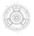
- FIG. 3 is a front view showing a state where a side plate is removed in the torsional excitation reduction device shown in FIG. 2.
- 2A and 2B are diagrams showing details of the drive plate alone shown in FIG. 1, wherein FIG. 1A is a front view thereof, and FIG. 1B is a sectional view taken along line BB in FIG.
- FIGS. 2A and 2B are diagrams showing details of the side plate alone shown in FIG. 1, in which FIG.
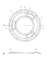
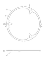
- FIGS. 2A and 2B are diagrams showing details of the hub plate alone shown in FIG. 1, in which FIG. 1A is a front view thereof, and FIG. 1B is a cross-sectional view taken along line DD in FIG. 2A and 2B are diagrams showing details of the floating equalizer alone shown in FIG. 1, in which FIG. 1A is a front view thereof, and FIG. 2B is a cross-sectional view taken along line EE in FIG. 4A and 4B are views showing details of the stopper members 49 and 50 shown in FIG. 3, wherein FIG. 5A is a front view thereof, and FIG.
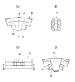
- FIG. 5B is a cross-sectional view taken along line FF in FIG. It is a figure which shows the detail only with the spring seat shown to FIG.2, 3, (A) is the front view, (B) is the left view of the figure (A), (C) is the figure of the figure (A). It is a right view.
- FIG. 4 is a diagram showing details of the canopy alone shown in FIG. 3, (A) is a front view thereof, (B) is a sectional view taken along line GG in FIG. 3, (C) is a plan view thereof, D) is a sectional view taken along line HH in FIG. It is explanatory drawing which shows the behavior of the torsional vibration reduction apparatus shown in FIG.
- FIG. 6 is a view showing a modification of the stopper members 49 and 50 shown in FIG. 3, and (A), (B), and (C) are cross-sectional views showing different modifications.
- FIGS. 1 to 10 are views showing a specific first embodiment of a long travel damper type torsional vibration reducing device (hereinafter simply referred to as “torsional vibration reducing device”) according to the present invention.
- 2 is a sectional view of the torsional vibration reducing device
- FIG. 2 is a front view of the torsional vibration reducing device of FIG. 1 as viewed from the right direction.
- FIG. 1 is taken along the line AA in FIG. A cross-sectional view is shown.
- FIG. 3 shows a state in which the side plate shown in FIG. 2 is removed for easy understanding of the structure of the torsional vibration reducing device.
- FIGS. 4 to 9 show details of the main components shown in FIGS.
- a crankshaft C corresponding to an output shaft of an internal combustion engine (engine) and an input shaft D of a transmission including an automatic transmission are arranged on the extension axis of the crankshaft C so as to face each other. Between these, a substantially disk-shaped torsional vibration reducing device 1 is disposed as a whole. As will be described later, a drive plate 2 that functions as an input-side rotating member in the torsional vibration reducing device 1 is connected to the crankshaft C by a plurality of mounting bolts 9 and also functions as an output-side rotating member in the torsional vibration reducing device 1. The hub plate 5 to be changed is splined to the input shaft D.
- the torsional vibration reduction device 1 is disposed to face each other with the hub plate 5, the floating equalizer 8 disposed on the outer periphery thereof, and the hub plate 5 and the floating equalizer 8 interposed therebetween.
- the drive plate 2 and the side plate 3 are provided.
- two sets of compression coil springs hereinafter referred to as “compressed coil springs” are arranged at approximately three equal positions. (Simply called “spring”) 17 and 18 are accommodated and arranged.
- stopper members 49 and 50 which are shorter than the total length of the springs 17 and 18 and have a cylindrical body portion and which are movable in the axial direction of the springs 17 and 18 are inserted in the springs 17 and 18, respectively.
- the stopper members 49 and 50 have a shape in which a part of a sphere is attached to both ends or one end thereof.
- the components arranged at equal circumferential positions are the same, and the reference numerals are omitted. Details of each component will be described later.
- the floating equalizer 8 and the hub plate 5 can rotate relative to each other, and the drive plate 2 can rotate relative to the floating equalizer 8 and the hub plate 5.
- the drive plate 2 and the side plate 3 are integrally fastened by a rivet 4 and are not relatively rotatable.
- the drive plate 2 and the side plate 3 are connected to the input side of the torsional vibration reduction device 1.
- the hub plate 5 functions as a rotating member, and the hub plate 5 also functions as an output-side rotating member of the torsional vibration reducing device 1.
- the floating equalizer 8 functions as an intermediate member.
- the drive plate 2 is a disk-like plate as a whole, and mounting bolts inserted into, for example, six bolt holes 10 that are evenly arranged on the innermost peripheral side. 9 is fastened to the crankshaft C.
- Cover parts 12 projecting toward the side opposite to the side plate 3 are bulged at approximately three equal positions in the circumferential direction of the drive plate 2, and slot parts 13 are formed at both ends of each cover part 12. It is.
- This cover portion 12 forms a spring accommodating portion of the input side rotating member together with a cover portion 14 on the side plate 3 side which will be described later, and a pair of springs 17 and 18 which are in series relation as described later in this spring accommodating portion. Will be housed.
- a flange portion 19 on the side plate 3 side described later and an annular outer peripheral mass 20 are fastened together by a plurality of rivets 4. Further, a ring gear 21 is press-fitted and fixed to the outer peripheral mass 20.
- the outer peripheral mass 20 functions as a mass body for stabilizing the rotation of the engine, and the ring gear 21 is for meshing with a starter gear (not shown) to give a rotational force for starting the engine.
- End surfaces 22 of the slot portions 13 at both ends of each cover portion 12 function as spring receiving portions, and both ends of a pair of springs 17 and 18 accommodated in the cover portion 12 are interposed via spring seats 23 described later. Thus, it is locked at the end face 22 of the slot portion 13.
- the side plate 3 that functions as an input side rotating member together with the drive plate 2 is an annular plate that is concentric and the same diameter as the drive plate 2 as shown in FIGS.
- the flange portion 19 is bent at the portion, and the flange portion 19 is fixed together with the drive plate 2 by the rivet 4 together with the outer peripheral mass 20 as described above.
- the side plate 3 is formed with cover portions 14 having slot portions 26 at both ends bulging toward the opposite side of the drive plate 2 at three locations in the circumferential direction.
- the side plate 3 side cover portion 14 forms a spring accommodating portion on the input rotating member side together with the cover portion 12 on the drive plate 2 side described above, and a pair of springs 17 and 18 in series relation are formed therein. Will be housed.
- both ends of the pair of springs 17 and 18 accommodated in the spring accommodating portion are engaged with the end surface 27 of each slot portion 26 via the spring seat 23 in the same manner as the drive plate 2 side.
- the end surface 27 of each slot portion 26 functions as a spring receiving portion.
- the hub plate 5 that functions as an output side rotating member is a circular shallow dish having a smaller diameter than the drive plate 2 and the side plate 3 as shown in FIGS.
- a boss portion 32 that rocks the female spline portion 31 is integrally formed at the center portion.
- the boss portion 32 is splined to the male spline portion on the input shaft D side.
- six escape holes 33 are formed at an equal pitch on the outer peripheral side of the boss portion 32 in the hub plate 5. As is apparent from FIG. 1, these relief holes 33 are used when fastening the mounting bolts 9 for fastening the drive plate 2 described above to the crankshaft C.
- a spring receiving recess 34 that functions as a spring accommodating portion of the output side rotating member is formed in the peripheral portion of the hub plate 5 so as to cut out three circumferentially equally divided portions.
- the positions of the spring receiving recesses 34 coincide with the positions of the cover portions 12 and 14 on the drive plate 2 side and the side plate 3 side that function as the spring accommodating portions of the input side rotating member.
- the pair of springs 17 and 18 that are in series as described above are accommodated in the space formed by both the cover parts 12 and 14 and the spring receiving recess 34 on the hub plate 5 side.
- both end surfaces 15 in the circumferential direction of the spring receiving recess 34 function as spring receiving portions where both ends of the pair of springs 17 and 18 are seated via the spring seat 23.
- the floating equalizer 8 that functions as an intermediate member is concentrically formed on the outer peripheral side of the hub plate 5 on the same plane as the outer peripheral edge of the hub plate 5. It is the ring-shaped thing to be arranged.
- an equalizer protrusion 41 that functions as an intermediate spring receiving portion is formed inward from the annular portion 8 a in the floating equalizer 8.
- the equalizer protrusion 41 includes a resin canopy 44 described later.
- both the drive plate 2 and the side plate 3 function as an input-side rotating member
- the hub plate 5 functions as an output-side rotating member, respectively
- the portions 12 and 14 function as the spring accommodating portion of the input side rotating member
- the spring receiving recesses 34 at the three circumferential directions on the hub plate 5 side respectively function as the spring accommodating portion of the output side rotating member. It is.
- the cover portions 12 and 14 of the drive plate 2 and the side plate 3 and the spring receiving recesses 34 of the hub plate 5 are paired with a pair of springs 17 and 18 in series. Is accommodated via a spring seat 23 made of resin, and an equalizer protrusion 41 (see FIG. 7) on the floating equalizer 8 side is interposed between two springs 17 and 18 that make a pair together with a canopy 44 described later. is doing.
- each of the pair of springs 17 and 18 in the three circumferential directions in FIG. 3 has a large spring constant (high rigidity) of the spring 18 positioned in the clockwise direction across the canopy 44, and is counterclockwise.
- the spring constant of the spring 17 positioned in the direction is smaller than that on the opposite side (low rigidity).
- the difference in the characteristics of both the springs 17 and 18 is determined, for example, by selection of the wire diameter, the number of turns, and the like.
- FIG. 8A and 8B are views showing details of the stopper members 49 and 50 inserted into the springs 17 and 18.
- FIG. 8A is a front view seen from the axial direction of the stopper members 49 and 50
- the stopper members 49 and 50 have a length shorter than the total length of the springs 17 and 18, and the shape is formed by a shape 51 of a part of a spherical surface (for example, a substantially hemisphere) whose both tops are formed integrally with a cylindrical body. Thus, it can move in the axial direction inside the springs 17 and 18.
- the material of the stopper members 49 and 50 is preferably made of a hard resin such as nylon 66.
- the radius r of a part of the spherical surface of the tip is preferably equal to or larger than the radius R of the cylindrical portion.
- FIGS. 9A and 9B are diagrams showing details of the resin spring seat 23 shown in FIGS. 2 and 3, wherein FIG. 9A is a front view thereof, FIG. 9B is a left side view thereof, and FIG. It is a right view of figure (A).
- cover portions 12 and 14 (see FIGS. 4 and 5) functioning as spring receiving portions and protrusions 45 that fit into both end surfaces of the spring accommodating recess 34 (see FIG. 6) are formed.
- a boss portion 46 is formed to support the end portions of the springs 17 and 18.
- the surface of the boss portion 46 that contacts the stopper members 49 and 50 corresponds to the convex spherical surface of the end surfaces of the stopper members 49 and 50.
- the concave spherical surface has a partial shape 52.
- the radius of the concave spherical surface is preferably equal to or slightly larger than the radius of the stopper portions 49 and 50.
- FIG. 10 shows details of the resin canopy 44 described above, (A) is a front view thereof, (B) is a GG sectional view, (C) is a plan view thereof, (D). Is a HH cross-sectional view.
- a slot portion 47 to be inserted into the equalizer protrusion 41 on the floating equalizer 8 side shown in FIG. 7 is formed, and each spring 17 is formed in the same manner as the spring seat 23. , 18 is formed to support the ends of the boss 18.
- the surface of the boss portion 48 that contacts the stopper members 49 and 50 also has a concave spherical partial shape 53 corresponding to the convex spherical surface of the end surfaces of the stopper members 49 and 50.
- it is desirable that the radius of the concave spherical surface is equal to or slightly larger than the radius of the stopper portions 49 and 50.
- the drive plate 2 and the side plate 3 that both function as an input-side rotating member cannot be rotated relative to each other, and function as an output-side rotating member between the drive plate 2 and the side plate 3.
- the hub plate 5 to be rotated is disposed so as to be relatively rotatable, and a total of three sets of springs 17 and 18 together with the floating equalizer 8 are interposed between the input side rotary member and the output side rotary member. It is disguised.
- the spring 17 having a small spring constant (small rigidity) and the spring 18 having a large spring constant (high rigidity) are both compressed and deformed, and the drive plate 2 from the crankshaft C side in FIG. Is transmitted to the hub plate 5, and is transmitted from the hub plate 5 to the input shaft D.
- the torsional vibration in the rotational torque transmission process as described above is absorbed or reduced by the compression deformation due to the elasticity of each pair of springs 17 and 18.
- stopper members 49 and 50 shorter than the total length of the springs 17 and 18 are inserted into the springs 17 and 18, respectively, so that the side plate 3 is included.
- the springs 17 and 18 are gradually compressed and deformed according to the respective spring constants, and the entire length of the spring 17 reaches the length of the stopper member 49 (in this case, the spring The total length of 18 has not yet reached the length of the stopper member 50).
- the entire length of the spring 17 remains the length of the stopper member 49 and the spring 18 is compressed and deformed. Finally, the entire length of the spring 18 reaches the length of the stopper member 50.
- both the drive plate 2 including the side plate 3 and the hub plate 5 can be rotated relative to each other.
- This stopper member 49 functions as a part of the boss part 46 of the spring seat 23 that functions as a part of the spring receiving part on the side of the spring 17 having a small spring constant and a part of the intermediate spring receiving part by having the shape described above.
- the canopy 44 can be brought into contact with the boss portion 48 on the spring 17 side having a small spring constant.
- stopper members 49 and 50 are cylindrical in shape and both end portions thereof are part of a spherical surface, the stopper members 49 and 50 are compressed when the springs 17 and 18 are compressed as described above. Even if the end portion of 50 comes into contact with the inner sliding surfaces of the springs 17 and 18, the movement of the stopper members 49 and 50 is not hindered, and the compression of the spring can proceed smoothly.
- the lengths of the stopper members 49 and 50 may be determined as appropriate according to the desired twist characteristics.
- boss portion 46 of the spring seat 23 and the boss portion 48 of the canopy 44 correspond to the end portion shapes of the stopper members 49 and 50, and the end portions thereof have a shape that is a part of a concave spherical surface. Therefore, the contact between the stopper members 49 and 50 and the boss portions 46 and 48 is smooth, and it is possible to prevent the member from being worn or twisted and to be used for a long time.
- FIG. 11A and 11B are diagrams showing the detailed behavior of the main part of the torsional vibration reducing device according to the present invention.
- FIG. 11A shows the neutral state
- FIG. 11B shows the contact state of the stopper member 49
- FIG. ) Is a cross-sectional view showing the contact state of the stopper member 50, respectively.
- the stopper members 49 and 50 are further compressed and deformed in proportion to the rotational load in accordance with the elastic coefficients of the stopper members 49 and 50.
- the compression deformation of the stopper members 49 and 50 may be slightly depending on the elastic modulus. All of these are based on the premise that the rigidity of the stopper members 49 and 50 is larger than the rigidity of the springs 17 and 18.
- the floating equalizer 8 is used as a medium regardless of the relative rotation direction of the drive plate 2 and the side plate 3 that are input side rotating members and the hub plate 5 that is an output side rotating member. Between the side plate 3 that is the rotating member and the floating equalizer 8, the stopper effect of the stopper member 49 inserted in the spring 17 is exhibited, while the hub plate 5 that is the output side rotating member and the floating equalizer 8
- the stopper effect by the stopper member 49 inserted in the spring 17 is necessarily limited before the wire 17 of the spring 17 having a small spring constant is brought into contact. Can do.
- the input / output side rotation is performed when rotating in the forward direction and when rotating in the reverse direction.
- the rotational torque characteristics between members can be made the same.
- the shape of the barrel portion of the stopper member may not be a column, but may be a prism, or a hollow cylinder or square tube inside, and is not limited to an elastic body but a rigid body. Also good.
- the shape of the end of the stopper member may be any shape that does not cause galling with the spring. For example, as shown in FIG. FIG. 12 (A)) or chamfered with R or C (FIG. 12 (B)) may be used.
- the body portion and the end portion of the stopper member do not necessarily have to be integrally formed, and for example, a sphere or a part of the sphere may be fixed to a column / cylinder or a rigid body (FIG. 12C). . Furthermore, it may be applied to only the most effective portion without subjecting all stopper members and / or bosses to the above-described processing.
- the springs 17 and 18 may have spring constants that are substantially equal to each other, not different spring constants. In this case, since the compression of the two springs proceeds substantially evenly, if the stopper member has an equal length, it will contact the spring receiving portion almost simultaneously, and if there is a difference in the length of the stopper member, The long stopper member comes into contact with the spring receiving portion first, and then the compression continues until the short stopper member comes into contact.
- the number of the two groups is three, and the number of the one group is three. In this case, the floating equalizer 8 and the canopy 44 are unnecessary.
Landscapes
- Engineering & Computer Science (AREA)
- General Engineering & Computer Science (AREA)
- Physics & Mathematics (AREA)
- Acoustics & Sound (AREA)
- Aviation & Aerospace Engineering (AREA)
- Mechanical Engineering (AREA)
- Mechanical Operated Clutches (AREA)
- Springs (AREA)
Abstract
Description
2・・・ドライブプレート(入力側回転部材)
3・・・サイドプレート(入力側回転部材)
5・・・ハブプレート(出力側回転部材)
8・・・フローティングイコライザ(中間部材)
8a・・環状部
15・・ばね収容凹部の端面(ばね受け部)
17・・ばね定数の小さい圧縮コイルばね
18・・ばね定数の大きい圧縮コイルばね
12・・カバー部(ばね収容部)
14・・カバー部(ばね収容部)
22・・スロット部端面(ばね受け部)
23・・スプリングシート
27・・スロット部端面(ばね受け部)
34・・ばね収容凹部(ばね収容部)
41・・イコライザ突起部(中間ばね受け部)
44・・キャノピー
46・・スプリングシートのボス部
48・・キャノピーのボス部
49・・ストッパ部材
50・・ストッパ部材
Claims (5)
- 正面視略円形の入力側回転部材と、
前記入力側回転部材と同心状に且つ正逆転方向に相対回転可能に対向配置された正面視略円形の出力側回転部材と、
前記入力側回転部材及び前記出力側回転部材の正面視軸心よりも半径方向外周側にそれぞれ形成され、両部材の相対回転方向両端部を弾性体受け部とする弾性体収容部と、
前記弾性体収容部にて前記入力側回転部材及び前記出力側回転部材の相対回転方向に沿って直列的に配置され、互いに相違する弾性係数を持つ少なくとも一対の弾性体と、
前記入力側回転部材及び前記出力側回転部材の半径方向において前記一対の弾性体よりも外周側に位置する環状部から該一対の弾性体側に突出してそれら一対の弾性体同士の間に介在する中間弾性体受け部を有する中間部材と、
前記一対の弾性体の少なくとも一方の内部に配設され、該弾性体の長さより短い長さを有し、該弾性体に係る弾性体収容部の弾性体受け部と前記中間部材の中間弾性体受け部とに当接可能な芯部材と
を具備することを特徴とする捻り振動低減装置。 - 正面視略円形の入力側回転部材と、
前記入力側回転部材と同心状に且つ正逆転方向に相対回転可能に対向配置された正面視略円形の出力側回転部材と、
前記入力側回転部材及び前記出力側回転部材の正面視軸心よりも半径方向外周側にそれぞれ形成され、両部材の相対回転方向両端部を弾性体受け部とする弾性体収容部と、
前記弾性体収容部にて前記入力側回転部材及び前記出力側回転部材の相対回転方向に沿って直列的に配置される第1の弾性体及び第2の弾性体と、
前記入力側回転部材及び前記出力側回転部材の半径方向において前記第1の弾性体及び前記第2の弾性体よりも外周側に位置する環状部から該第1の弾性体及び該第2の弾性体側に突出してそれら弾性体同士の間に介在する中間弾性体受け部を有する中間部材と、
前記第1の弾性体及び前記第2の弾性体の内部にそれぞれ配設される第1及び第2の芯部材であって、それぞれ対応する弾性体の長さより短い長さを有し、該対応する弾性体に係る弾性体収容部の弾性体受け部と前記中間部材の中間弾性体受け部とに当接可能な第1及び第2の芯部材と
を具備することを特徴とする捻り振動低減装置。 - 正面視略円形の入力側回転部材と、
前記入力側回転部材と同心状に且つ正逆転方向に相対回転可能に対向配置された正面視略円形の出力側回転部材と、
前記入力側回転部材及び前記出力側回転部材の正面視軸心よりも半径方向外周側にそれぞれ形成され、両部材の相対回転方向両端部を弾性体受け部とする弾性体収容部と、
前記弾性体収容部にて前記入力側回転部材及び前記出力側回転部材の相対回転方向に沿って配置される弾性体と、
前記弾性体の内部に配設される芯部材であって、該弾性体の長さより短い長さを有し、該弾性体に係る弾性体収容部の弾性体受け部に当接可能な芯部材と
を具備することを特徴とする捻り振動低減装置。 - 請求項1乃至3のいずれか1項記載の捻り振動低減装置において、
前記芯部材は、その両端のうち少なくとも一端は球面端部に係る形状を有し、これと対応する弾性体受け部は前記球面端部に係る形状と嵌合する凹部形状を有する捻り振動低減装置。 - 前記芯部材は樹脂によってなる請求項1乃至3のいずれか1項記載の捻り振動低減装置。
Priority Applications (2)
| Application Number | Priority Date | Filing Date | Title |
|---|---|---|---|
| JP2014533161A JPWO2014034941A1 (ja) | 2012-09-03 | 2013-09-03 | 捻り振動低減装置 |
| EP13834197.9A EP2902659A1 (en) | 2012-09-03 | 2013-09-03 | Torsional vibration reduction device |
Applications Claiming Priority (2)
| Application Number | Priority Date | Filing Date | Title |
|---|---|---|---|
| JP2012193057 | 2012-09-03 | ||
| JP2012-193057 | 2012-09-03 |
Publications (1)
| Publication Number | Publication Date |
|---|---|
| WO2014034941A1 true WO2014034941A1 (ja) | 2014-03-06 |
Family
ID=50183739
Family Applications (1)
| Application Number | Title | Priority Date | Filing Date |
|---|---|---|---|
| PCT/JP2013/073602 WO2014034941A1 (ja) | 2012-09-03 | 2013-09-03 | 捻り振動低減装置 |
Country Status (3)
| Country | Link |
|---|---|
| EP (1) | EP2902659A1 (ja) |
| JP (1) | JPWO2014034941A1 (ja) |
| WO (1) | WO2014034941A1 (ja) |
Cited By (4)
| Publication number | Priority date | Publication date | Assignee | Title |
|---|---|---|---|---|
| EP3026294B1 (en) | 2014-11-25 | 2018-03-14 | Aisin Seiki Kabushiki Kaisha | Damper apparatus |
| JP2020112201A (ja) * | 2019-01-10 | 2020-07-27 | アイシン精機株式会社 | ダンパ装置 |
| JP2022515147A (ja) * | 2018-12-20 | 2022-02-17 | ヴァレオ アンブラヤージュ | 直列に配置されたバネを有するトルク伝達装置、および当該装置を備えるトルク伝達システム |
| JP7412539B2 (ja) | 2019-08-30 | 2024-01-12 | ヴァレオ アンブラヤージュ | トルクを伝達する装置 |
Citations (7)
| Publication number | Priority date | Publication date | Assignee | Title |
|---|---|---|---|---|
| JPS56120424U (ja) * | 1980-02-15 | 1981-09-14 | ||
| JPS63129744U (ja) * | 1987-02-18 | 1988-08-24 | ||
| JPH04249654A (ja) * | 1990-06-01 | 1992-09-04 | General Motors Corp <Gm> | クラッチ及びダンパアセンブリ |
| JPH0577891A (ja) | 1991-09-11 | 1993-03-30 | Japan Tobacco Inc | 液体充填機の液だれ防止機構 |
| JP2007285335A (ja) | 2006-04-13 | 2007-11-01 | Valeo Unisia Transmission Kk | 捩り振動低減装置 |
| JP2009019640A (ja) | 2007-07-10 | 2009-01-29 | Valeo Unisia Transmission Kk | 捩り振動低減装置 |
| JP2009150431A (ja) | 2007-12-19 | 2009-07-09 | Valeo Unisia Transmission Kk | 捩り振動低減装置 |
-
2013
- 2013-09-03 JP JP2014533161A patent/JPWO2014034941A1/ja active Pending
- 2013-09-03 EP EP13834197.9A patent/EP2902659A1/en not_active Withdrawn
- 2013-09-03 WO PCT/JP2013/073602 patent/WO2014034941A1/ja active Application Filing
Patent Citations (7)
| Publication number | Priority date | Publication date | Assignee | Title |
|---|---|---|---|---|
| JPS56120424U (ja) * | 1980-02-15 | 1981-09-14 | ||
| JPS63129744U (ja) * | 1987-02-18 | 1988-08-24 | ||
| JPH04249654A (ja) * | 1990-06-01 | 1992-09-04 | General Motors Corp <Gm> | クラッチ及びダンパアセンブリ |
| JPH0577891A (ja) | 1991-09-11 | 1993-03-30 | Japan Tobacco Inc | 液体充填機の液だれ防止機構 |
| JP2007285335A (ja) | 2006-04-13 | 2007-11-01 | Valeo Unisia Transmission Kk | 捩り振動低減装置 |
| JP2009019640A (ja) | 2007-07-10 | 2009-01-29 | Valeo Unisia Transmission Kk | 捩り振動低減装置 |
| JP2009150431A (ja) | 2007-12-19 | 2009-07-09 | Valeo Unisia Transmission Kk | 捩り振動低減装置 |
Cited By (5)
| Publication number | Priority date | Publication date | Assignee | Title |
|---|---|---|---|---|
| EP3026294B1 (en) | 2014-11-25 | 2018-03-14 | Aisin Seiki Kabushiki Kaisha | Damper apparatus |
| JP2022515147A (ja) * | 2018-12-20 | 2022-02-17 | ヴァレオ アンブラヤージュ | 直列に配置されたバネを有するトルク伝達装置、および当該装置を備えるトルク伝達システム |
| JP2020112201A (ja) * | 2019-01-10 | 2020-07-27 | アイシン精機株式会社 | ダンパ装置 |
| JP7230514B2 (ja) | 2019-01-10 | 2023-03-01 | 株式会社アイシン | ダンパ装置 |
| JP7412539B2 (ja) | 2019-08-30 | 2024-01-12 | ヴァレオ アンブラヤージュ | トルクを伝達する装置 |
Also Published As
| Publication number | Publication date |
|---|---|
| JPWO2014034941A1 (ja) | 2016-08-08 |
| EP2902659A1 (en) | 2015-08-05 |
Similar Documents
| Publication | Publication Date | Title |
|---|---|---|
| JP6274796B2 (ja) | 自動車用のトルク伝達装置 | |
| US10047844B2 (en) | Dynamic damper device | |
| WO2011067815A1 (ja) | トルク変動吸収装置 | |
| CN108223689B (zh) | 扭矩变动吸收装置 | |
| WO2014034941A1 (ja) | 捻り振動低減装置 | |
| JP2008303995A (ja) | トルク変動吸収装置 | |
| US10274068B2 (en) | Spring assembly and lock-up device for torque converter including same | |
| KR100408803B1 (ko) | 댐퍼 기구 | |
| JP2013036530A (ja) | 回転変動吸収クランクプーリ | |
| US6676525B2 (en) | Damper mechanism | |
| JP2014532842A (ja) | 改良型デュアルマスフライホイール | |
| WO2017057490A1 (ja) | ダンパ装置 | |
| JP2013167309A (ja) | 捻り振動低減装置 | |
| WO2016021741A1 (ja) | 発進装置 | |
| JP5817918B2 (ja) | 捩り振動減衰装置 | |
| JP2012159111A (ja) | 捩りダンパ装置 | |
| JP5131369B2 (ja) | トルク変動吸収装置 | |
| JP2002213535A (ja) | ダンパー機構 | |
| JP2014228124A (ja) | クラッチディスク | |
| JP2022030692A (ja) | ダンパ装置 | |
| JP5775407B2 (ja) | トルク変動吸収装置 | |
| JP4730225B2 (ja) | ダンパ装置 | |
| JP7002402B2 (ja) | ダンパー装置 | |
| JP2004183871A (ja) | スプリング、スプリング組立体、ダンパー機構 | |
| JP2017172707A (ja) | トルク変動吸収装置 |
Legal Events
| Date | Code | Title | Description |
|---|---|---|---|
| 121 | Ep: the epo has been informed by wipo that ep was designated in this application |
Ref document number: 13834197 Country of ref document: EP Kind code of ref document: A1 |
|
| ENP | Entry into the national phase |
Ref document number: 2014533161 Country of ref document: JP Kind code of ref document: A |
|
| NENP | Non-entry into the national phase |
Ref country code: DE |
|
| REEP | Request for entry into the european phase |
Ref document number: 2013834197 Country of ref document: EP |
|
| WWE | Wipo information: entry into national phase |
Ref document number: 2013834197 Country of ref document: EP |