WO2014027375A1 - Plate glass inspection unit and manufacturing facility - Google Patents
Plate glass inspection unit and manufacturing facility Download PDFInfo
- Publication number
- WO2014027375A1 WO2014027375A1 PCT/JP2012/005145 JP2012005145W WO2014027375A1 WO 2014027375 A1 WO2014027375 A1 WO 2014027375A1 JP 2012005145 W JP2012005145 W JP 2012005145W WO 2014027375 A1 WO2014027375 A1 WO 2014027375A1
- Authority
- WO
- WIPO (PCT)
- Prior art keywords
- plate glass
- inspection device
- inspection
- glass
- plate
- Prior art date
Links
Images

Classifications
-
- G—PHYSICS
- G01—MEASURING; TESTING
- G01N—INVESTIGATING OR ANALYSING MATERIALS BY DETERMINING THEIR CHEMICAL OR PHYSICAL PROPERTIES
- G01N21/00—Investigating or analysing materials by the use of optical means, i.e. using sub-millimetre waves, infrared, visible or ultraviolet light
- G01N21/84—Systems specially adapted for particular applications
- G01N21/88—Investigating the presence of flaws or contamination
- G01N21/89—Investigating the presence of flaws or contamination in moving material, e.g. running paper or textiles
- G01N21/892—Investigating the presence of flaws or contamination in moving material, e.g. running paper or textiles characterised by the flaw, defect or object feature examined
- G01N21/896—Optical defects in or on transparent materials, e.g. distortion, surface flaws in conveyed flat sheet or rod
-
- G—PHYSICS
- G01—MEASURING; TESTING
- G01N—INVESTIGATING OR ANALYSING MATERIALS BY DETERMINING THEIR CHEMICAL OR PHYSICAL PROPERTIES
- G01N21/00—Investigating or analysing materials by the use of optical means, i.e. using sub-millimetre waves, infrared, visible or ultraviolet light
- G01N21/84—Systems specially adapted for particular applications
- G01N21/88—Investigating the presence of flaws or contamination
- G01N21/95—Investigating the presence of flaws or contamination characterised by the material or shape of the object to be examined
- G01N21/958—Inspecting transparent materials or objects, e.g. windscreens
Definitions
- the present invention relates to a plate glass inspection unit that performs plate glass inspection on a production line. Moreover, it is related with the manufacturing equipment of the plate glass containing this test
- Patent Document 1 discloses “Glass Substrate Shape Measuring Device and Measuring Method”
- Patent Document 2 discloses “Foreign Substance Inspection Device and Inspection Method”
- Patent Document 3 discloses.
- “Defect inspection apparatus and method for plate-like transparent body” is disclosed
- Patent Document 4 discloses “end surface inspection method and end surface inspection apparatus for light-transmitting rectangular object”.
- the present invention has been made in view of the above circumstances, and an object thereof is to provide an inspection unit capable of efficiently inspecting a plate glass having a forming direction.
- An inspection unit is an inspection unit that inspects a rectangular plate glass having a forming direction while feeding it downstream, and a parallel edge inspection device that inspects a side extending in the forming direction of the plate glass that passes therethrough.
- a rotating device that rotates the plate glass so that the forming direction is orthogonal to the conveying direction
- an orthogonal edge inspection device that inspects a side that is orthogonal to the forming direction of the passing plate glass
- a surface inspection that inspects the entire surface of the passing plate glass.
- a line inspection device that inspects the surface of the plate glass passing through a line perpendicular to the molding direction, and the parallel edge inspection is provided on one side of the upstream and downstream sides of the rotating device.
- An apparatus is disposed, and the orthogonal edge inspection apparatus, the surface inspection apparatus, and the line inspection apparatus are disposed on the other side.
- the plate glass having the molding direction is likely to have defects such as scratches and striae in the molding direction.
- the surface inspection apparatus and the line inspection apparatus can accurately perform the inspection of the plate glass in the direction orthogonal to the forming direction.
- these both inspection apparatuses are arrange
- the parallel edge inspection device detects defects on both sides extending in the forming direction of the plate glass and calculates a dimension in a direction orthogonal to the forming direction of the plate glass based on the positions of the both sides.
- the orthogonal edge inspection device detects defects on both sides orthogonal to the forming direction of the plate glass and calculates the dimension in the forming direction of the plate glass based on the positions of the both sides.
- the surface of the plate glass and internal defects may be detected, and the line inspection device may be configured to measure the thickness of the plate glass and detect the striae of the plate glass.
- the inspection unit further includes an off-line inspection apparatus, the off-line inspection apparatus including a plate thickness sensor for measuring the plate thickness of the plate glass, a stress measurement sensor for measuring the residual stress of the plate glass, and the plate glass.
- the plate thickness sensor and the stress measurement sensor may both be provided at the drive unit and move at the same time.
- Both plate thickness measurement and stress measurement take a relatively long time if performed accurately, but according to the above configuration, these inspections can be performed simultaneously, so the inspection time is shortened and the accuracy is very high. And it is highly efficient, and quality control of the plate glass becomes easy.
- the manufacturing equipment for plate glass includes the above-described inspection unit, and a cleaning unit that is located on the upstream side of the inspection unit and has a blowout port that blows air to the passing plate glass, It extends in a direction inclined with respect to a direction orthogonal to the conveying direction of the plate glass.
- An inspection unit is an inspection unit that inspects a rectangular plate glass having a forming direction while carrying it in the forming direction and sending it downstream, so that the forming direction is orthogonal to the conveying direction.
- the rotating device that rotates the plate glass the all-edge inspection device that inspects the four sides of the plate glass by stopping feeding, the surface inspection device that inspects the entire surface of the plate glass that passes, and the surface of the plate glass that passes.
- a line inspection device for inspecting a line perpendicular to the forming direction, and the surface inspection device and the line inspection device are arranged downstream of the rotating device.
- an all-edge inspection device is adopted instead of the parallel edge inspection device and the orthogonal edge inspection device, but the surface inspection device and the line inspection device are gathered and arranged on the downstream side of the rotation device. Even in this case, the plate glass can be inspected efficiently.
- An inspection unit is an inspection unit that inspects a rectangular plate glass having a forming direction in a direction orthogonal to the forming direction and sends it downstream, and stops feeding one end.
- An all-edge inspection device that inspects the four sides of the plate glass, a surface inspection device that inspects the entire surface of the plate glass that passes through, a line inspection device that inspects a line perpendicular to the molding direction among the surfaces of the plate glass that passes through, It has.
- the all-edge inspection apparatus detects defects on the four sides of the glass sheet, and measures the dimension in the molding direction of the glass sheet and the dimension in the direction orthogonal to the molding direction based on the position of each side.
- the surface inspection device detects defects on the surface and inside of the plate glass, and the line inspection device measures the thickness of the plate glass and detects striae of the plate glass. May be.
- an inspection unit capable of efficiently inspecting a plate glass having a forming direction can be provided.
- FIG. 1 is a schematic plan view showing the main part of the production facility according to the first embodiment of the present invention.
- FIG. 2 is a schematic perspective view of the off-line inspection apparatus shown in FIG.
- FIG. 3 is a schematic plan view showing the main part of the production facility according to the second embodiment of the present invention.
- FIG. 4 is a schematic plan view showing the main part of the production facility according to the third embodiment of the present invention.
- FIG. 5 is a schematic plan view showing the main part of the production facility according to the fourth embodiment of the present invention.
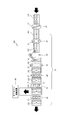
- FIG. 1 is a schematic plan view showing a main part of the manufacturing facility 100 according to the present embodiment.
- the plate glass 101 is conveyed from right to left on the paper surface by a feed roller or the like.
- the plate glass 101 denoted by reference signs A to H in the figure indicates the direction and position of the plate glass 101 over time.
- position A the position of the plate glass 101 denoted by reference numerals A to H in the drawing will be described as “position A”, for example.
- the plate glass 101 of the present embodiment is formed so as to be sent out from a melting furnace (not shown) located on the upstream side of the production line, and has a “forming direction”.
- the plate glass 101 is formed in a rectangular shape (rectangular shape), and the long side and the forming direction are parallel to each other.
- the manufacturing facility 100 includes a cleaning unit 10 and an inspection unit 20.
- the cleaning unit 10 is a unit that cleans the passing glass plate 101.
- the glass sheet 101 is carried into the cleaning unit 10 after being cut into an arbitrary size in a previous process (not shown).
- the cleaning unit 10 removes chips and the like attached when the plate glass 101 is cut, and conveys the plate glass 101 to the inspection unit 20 located on the downstream side.
- the glass plate 101 is carried into the cleaning unit 10 in the molding direction. That is, the plate glass 101 is carried into the cleaning unit 10 such that the long side coincides with the carry-in direction.
- the cleaning unit 10 has an air outlet 11 that blows air to the passing glass plate 101.
- the plate glass 101 passes through the air outlet 11 when moving from the position A to the position B.
- the blower outlet 11 does not extend in a direction orthogonal to the conveyance direction of the plate glass 101 but extends in a direction inclined with respect to a direction orthogonal to the conveyance direction. According to such a configuration, it is possible to prevent air force from being applied to the plate glass 101 at once when the plate glass 101 reaches the air outlet 11, and gently apply air force to the plate glass 101. Therefore, it is possible to prevent fluttering in the vertical direction of the plate glass 101 that may occur when the plate glass 101 passes through the air outlet 11.
- the inspection unit 20 is a unit that inspects the plate glass 101 while conveying it downstream.
- the plate glass 101 is inspected by the inspection unit 20 while moving from the position B to the position H.
- the plate glass 101 is carried into the inspection unit 20 as it is without rotating from the cleaning unit 10 described above. That is, the plate glass 101 is transported to the inspection unit 20 so that the molding direction and the transport direction coincide.
- the inspection unit 20 includes a parallel edge inspection device 30, a rotation device 40, an orthogonal edge inspection device 50, a surface inspection device 60, a line inspection device 70, and a high-speed stress measurement device 80. And an off-line inspection device 90. These apparatuses are arranged on a straight line except for the off-line inspection apparatus 90.
- the parallel edge inspection apparatus 30 is an apparatus for inspecting the presence or absence of defects on the side (long side) extending in the forming direction of the passing plate glass 101.
- the parallel edge inspection device 30 has two CCD cameras 31. Each CCD camera 31 is disposed above the plate glass 101 and at positions corresponding to both long sides of the plate glass 101. When the plate glass 101 is moved from the position B to the position C by the CCD camera 31, the long side of the plate glass 101 is photographed. Then, the parallel edge inspection device 30 determines whether there are any defects (chips, cracks, grinding unevenness, and dirt) on the long side based on the image data obtained by the image capturing by the CCD camera 31.
- the CCD cameras 31 may be simultaneously installed at three locations above, below and on the side of the plate glass 101.
- Rotating device 40 is a device that rotates plate glass 101 horizontally.
- the plate glass 101 is rotated 90 degrees so that the long side is orthogonal to the transport direction. Thereby, the plate glass 101 is conveyed in the direction orthogonal to the forming direction on the downstream side of the rotating device 40.
- the rotating device 40 sucks and lifts the plate glass 101 at the position C by the arm 41 having a suction cup, and lowers it to the position D after rotating it.
- the specific configuration of the rotating device 40 is not limited to this, and may be rotated by any method.
- the arrangement of the devices constituting the inspection unit 20 is as follows. That is, the parallel edge inspection device 30 is arranged on the upstream side of the rotation device 40. Further, an orthogonal edge inspection device 50, a surface inspection device 60, a line inspection device 70, and a high-speed stress measurement device 80 are disposed on the downstream side of the rotating device 40. The position of the high-speed stress measuring device 80 is not particularly limited. Moreover, the orthogonal edge inspection apparatus 50, the surface inspection apparatus 60, and the line inspection apparatus 70 should just be located in the downstream of the rotation apparatus 40, and the position of these three apparatuses may be replaced.
- the orthogonal edge inspection apparatus 50 is an apparatus that inspects the presence or absence of a defect on a side (short side) orthogonal to the forming direction of the plate glass 101 that passes therethrough.
- the orthogonal edge inspection device 50 has two CCD cameras 51.
- the CCD camera 51 is disposed above the plate glass 101 and at a position corresponding to the short side of the plate glass 101.
- the plate glass 101 is moved from the position D to the position E by the CCD camera 51, the short side of the plate glass 101 is photographed. Then, based on the image data obtained by photographing, it is determined whether there is a defect on the short side.
- the CCD cameras 51 may be simultaneously installed at three locations above, below and on the side of the plate glass 101.
- the surface inspection device 60 is a device that inspects the entire surface of the passing glass plate 101.
- the surface inspection apparatus 60 has a plurality of CCD cameras 61.
- the CCD camera 61 is arranged above the plate glass 101 in a direction orthogonal to the transport direction.
- the plate glass 101 is moved from the position E to the position F by these CCD cameras 61, the entire surface of the plate glass 101 is photographed.
- it is determined whether there are any defects (scratches, adhesion of foreign matter) on the surface of the plate glass 101 and internal defects (mixing of bubbles, foreign matter).
- the scratch on the surface of the plate glass 101 is easily formed so as to extend in the molding direction. Therefore, by observing the surface in the direction orthogonal to the molding direction, if there is a scratch, the image data is likely to change, and the scratch is easy to detect. That is, according to such a configuration, the surface inspection accuracy can be improved.
- the on-line inspection apparatus 70 is an apparatus that inspects the surface of the plate glass 101 that passes therethrough on a line orthogonal to the forming direction (moving relatively in a direction orthogonal to the forming direction).
- the line inspection apparatus 70 includes a thickness measurement sensor 71 and a striae inspection sensor 72.
- the thickness measurement sensor 71 observes light that is irradiated from above the plate glass 101 and reflected on the upper and lower surfaces of the plate glass 101.
- the on-line inspection device 70 can measure the thickness of the plate glass 101 at the inspection position based on this observation result.
- the striae inspection sensor 72 observes light that has passed through the plate glass 101.
- the line inspection apparatus 70 can detect the striae in the plate glass 101 based on the observation result. In FIG.
- the thickness of the plate glass 101 is measured and the presence or absence of striae is inspected.
- the plate glass 101 having the forming direction is likely to change in thickness in a direction orthogonal to the forming direction.
- the striae are formed so as to extend in the molding direction. Therefore, the abnormal thickness and striae of the plate glass can be detected with high accuracy by inspecting the thickness and striae while relatively moving in the direction orthogonal to the forming direction as in this embodiment.
- the high-speed stress measuring device 80 is a device that measures the residual stress in the plate glass 101 at high speed.
- the high-speed stress measurement device 80 has a plurality of stress measurement sensors 81.
- the stress measurement sensor 81 is arranged above the plate glass 101 and arranged in a direction orthogonal to the conveyance direction.
- the high-speed stress measuring device 80 has a light emitting unit (not shown) located below the plate glass 101.
- the light emitting unit emits laser light toward the lower surface of the plate glass 101.
- the laser light passes through the plate glass 101 and is received by the stress measurement sensor 81.
- the high-speed stress measuring device 80 calculates the residual stress based on the angle of the laser beam incident on the stress measuring sensor 81.
- the high-speed stress measurement apparatus 80 of the present embodiment a plurality of stress measurement sensors 81 and light emitting units are arranged and the number of measurements is reduced by reducing the number of measurements. High speed is realized.
- the offline inspection apparatus 90 is an apparatus that inspects the plate glass 101 taken out from the production line.
- the plate glass 101 may be taken out automatically or manually.
- the plate glass 101 to be inspected by the off-line inspection apparatus 90 is configured to be taken out from the position G.
- the residual stress generated in the plate glass 101 and the thickness of the plate are measured simultaneously.
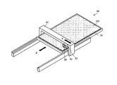
- FIG. 2 is a schematic perspective view of the off-line inspection apparatus 90.
- the plate glass 101 is placed on the plate glass 101 for inspection.
- the direction parallel to the long side of the plate glass (upper right and lower left direction in the drawing) is defined as the “X direction”, and the short side of the plate glass 101 is set.
- the parallel direction (upper left and lower right on the page) is defined as the “Y direction”.
- the off-line inspection device 90 includes a table 91, a drive unit 92, a plate thickness sensor 93, and a stress measurement sensor 94.
- the table 91 is a table for placing the plate glass 101 horizontally, and is configured to be slidable in the X direction.
- the table 91 is regularly formed with a plurality of through holes (not shown) penetrating in a direction perpendicular to the surface.
- a light emitting unit (not shown) is disposed below the table 91. When laser light is emitted from the light emitting unit, the laser light is irradiated to the plate glass 101 through the through hole.
- the drive unit 92 is positioned above the table 91 and drives in the Y direction along a rail 95 extending in the Y direction.
- the drive unit 92 is provided with a plate thickness sensor 93 and a stress measurement sensor 94. That is, the plate thickness sensor 93 and the stress measurement sensor 94 are arranged adjacent to each other and are configured to move simultaneously with the drive unit 92 in the Y direction. As the stress measurement sensor 94 moves in the Y direction, the above-described light emitting unit also moves in the Y direction.
- the plate thickness sensor 93 can inspect the warpage of the plate glass 101 and receives light reflected by the plate glass 101. And the curvature of the plate glass 101 is detected based on the angle of the light received by the plate thickness sensor 93. Further, the plate thickness of the plate glass 101 can be calculated from this detection data.
- the stress measurement sensor 94 is basically the same as the stress measurement sensor 81 of the high-speed stress measurement device 80 described above. However, the stress measurement sensor 94 of the off-line inspection apparatus 90 has higher detection accuracy than the stress measurement sensor 81 of the high-speed stress measurement apparatus 80.
- the residual stress is calculated (measured based on the actual plate thickness of the plate glass 101 calculated by the plate thickness sensor 93 as well as the angle of the laser light from the light emitting portion received by the stress measurement sensor 94. )is doing.
- the residual stress is not the same if the plate thickness of the plate glass 101 is different. That is, information on the thickness of the plate glass 101 is necessary for accurate measurement of residual stress.
- an apparatus for measuring the residual stress of the plate glass 101 has been provided independently of an apparatus capable of measuring the plate thickness of the plate glass 101. Therefore, the residual stress is calculated on the assumption that the thickness of the plate glass 101 is constant, and as a result, an error of about 10% has occurred.
- the off-line inspection apparatus 90 of this embodiment includes both the plate thickness sensor 93 and the stress measurement sensor 94, the residual stress can be calculated based on the actual plate thickness of the plate glass 101. As a result, the residual stress can be measured with high accuracy, and quality control is facilitated.
- the off-line inspection apparatus 90 inspects the plate glass 101 as follows. First, the X-direction position of the table 91 is adjusted so that the plate thickness sensor 93 and the stress measurement sensor 94 can measure the vicinity of one short side of the plate glass 101. Next, while the position of the table 91 is fixed, the position of the drive unit 92 is gradually changed in the Y direction from one long side of the plate glass 101 to the other long side, and the plate thickness measurement and stress measurement of the plate glass 101 are performed. Then, when the driving unit 92 reaches the other long side of the plate glass 101, this time, the table 91 is slightly moved in the X direction, and in the same manner, the driving unit from the other long side of the plate glass 101 to one long side.
- Plate thickness measurement and stress measurement are performed while changing the position of 92 little by little. The above operation is repeated, and when the entire glass plate 101 is inspected, the off-line inspection ends.
- the plate thickness measurement and the stress measurement both take a relatively long time if performed accurately, but the off-line inspection apparatus 90 of the present embodiment can perform these inspections at the same time. Very accurate and efficient.
- the inspection unit 20 of the present embodiment includes a surface inspection device 60 and a line inspection device 70 that can detect defects with high accuracy when inspection is performed from a direction orthogonal to the molding direction. And since these apparatuses are collected and arrange
- the inspection unit 20 includes the high-speed stress measuring device 80. However, since the residual stress of the plate glass 101 can also be measured by the offline inspection device 90, the inspection unit 20 does not include the offline inspection device 90. Also good.
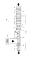
- FIG. 3 is a schematic plan view showing a main part of the manufacturing facility 200 according to the present embodiment. If this embodiment and 1st Embodiment are contrasted, the manufacturing equipment 200 which concerns on this embodiment concerns on 1st Embodiment in terms of the carrying-in direction of the plate glass 101, and the arrangement
- the glass plate 101 is carried into the cleaning unit 10 and the inspection unit 20 in a direction orthogonal to the forming direction.
- the arrangement order of the devices constituting the inspection unit 20 is as follows when the rotation device 40 is used as a reference. That is, the orthogonal edge inspection device 50, the surface inspection device 60, and the line inspection device 70 are arranged on the upstream side of the rotating device 40. A parallel edge inspection device 30 and a high-speed stress measurement device 80 are disposed on the downstream side of the rotation device 40.
- the surface inspection device 60, the line inspection device 70, and the like are gathered and arranged upstream of the rotation device 40. Therefore, as in the case of the first embodiment, the plate glass 101 There is no need to repeat the direction change, and high-precision inspection can be performed efficiently.
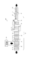
- FIG. 4 is a schematic plan view showing a main part of the manufacturing facility 300 according to the present embodiment.
- the inspection unit 20 does not include the parallel edge inspection device 30 and the orthogonal edge inspection device 50, and instead, all edge inspection is performed.
- the configuration differs from the manufacturing facility 100 according to the first embodiment in that the device 35 is provided. In other respects, both facilities basically have the same configuration. Therefore, here, the description will focus on the all-edge inspection device 35.
- the all edge inspection device 35 of this embodiment is a device that inspects the four sides of the plate glass 101.
- the all edge inspection device 35 has four CCD cameras 36.
- Each CCD camera 36 is located above the plate glass 101 and is disposed at a position corresponding to each of the four sides of the plate glass 101.
- the plate glass 101 carried into the all edge inspection device 35 is temporarily stopped from being fed, and in this state, each CCD camera 36 moves along the corresponding side. Then, while each CCD camera 36 moves along the corresponding side, the side is photographed. Then, the all edge inspection device 35 determines whether there is a defect on each side based on the image data obtained by photographing with each CCD camera 36.
- the all edge inspection apparatus 35 includes the four CCD cameras 36 has been described.
- a single CCD camera 36 may be provided and moved along all four sides of the plate glass 101.
- the CCD camera 36 may be simultaneously installed at three locations above, below, and side of each side of the plate glass 101.
- the position of the short side and the long side of the plate glass 101 can be measured from the image data, and the long side dimension and the short side dimension of the plate glass 101 can be calculated based on these measurement results.
- the all edge inspection device 35 is disposed on the downstream side of the rotating device 40, but may be disposed on the upstream side of the rotating device 40.
- the all edge inspection device 35 is employed, but the surface inspection device 60 and the line inspection device 70 are gathered downstream of the rotation device 40. Even if it is the case of this embodiment, it can test
- FIG. 5 is a schematic plan view showing a main part of the manufacturing facility 400 according to the present embodiment.
- the inspection unit 20 does not include the parallel edge inspection device 30 and the orthogonal edge inspection device 50, and instead, all edge inspection is performed.
- the configuration is different from that of the manufacturing facility 200 according to the second embodiment in that the device 35 is provided and the rotating device 40 is not provided. In other respects, both facilities basically have the same configuration.
- the all-edge inspection apparatus 35 of the present embodiment is the same as the all-edge inspection apparatus 35 described in the third embodiment.
- the surface inspection device 60 and the on-line inspection device 70 can perform high-precision inspection without rotating the plate glass 101 and changing the direction. Is possible. Therefore, the rotation device 40 can be omitted in the inspection unit 20 of the present embodiment.
- the surface inspection device 60 and the line inspection device 70 are collected and arranged, and the plate glass 101 can be efficiently inspected as in the other embodiments.
- an inspection unit capable of efficiently inspecting a plate glass having a forming direction can be provided. Therefore, this invention is useful in the technical field of the manufacturing equipment of the plate glass containing an inspection unit.
Abstract
Description
まず、図1及び図2を参照して、本発明の第1実施形態に係る板ガラスの製造設備100について説明する。図1は、本実施形態に係る製造設備100の要部を示した概略平面図である。図中、板ガラス101は送りローラー等によって紙面右から左へと搬送される。図のAからHの符号を付した板ガラス101は、時間の経過に伴う板ガラス101の向き及び位置を示している。以下では、図中においてAからHまでの符号を付した板ガラス101の位置を例えば「位置A」などと称して説明する。また、本実施形態の板ガラス101は、製造ラインの上流側に位置する溶解炉(図示せず)から送り出されるようにして成形されており、「成形方向」を有している。板ガラス101は長方形状(矩形状)に形成されているが、その長辺と成形方向が平行の関係にある。図1に示すように、本実施形態に係る製造設備100は、清掃ユニット10と、検査ユニット20と、を備えている。 (First embodiment)
First, with reference to FIG.1 and FIG.2, the
次に、図3を参照して、本発明の第2実施形態に係る板ガラス101の製造設備200について説明する。図3は、本実施形態に係る製造設備200の要部を示した概略平面図である。本実施形態と第1実施形態を対比すると、本実施形態に係る製造設備200は、板ガラス101の搬入方向、及び、検査ユニット20を構成する装置の配置順の点において、第1実施形態に係る製造設備100と異なる。それ以外の点については、両設備は基本的に同じ構成を有している。 (Second Embodiment)
Next, with reference to FIG. 3, the
次に、図4を参照して、本発明の第3実施形態に係る板ガラス101の製造設備300について説明する。図4は、本実施形態に係る製造設備300の要部を示した概略平面図である。本実施形態と第1実施形態を対比すると、本実施形態に係る製造設備300は、検査ユニット20が平行エッジ検査装置30及び直交エッジ検査装置50を備えておらず、これらに代えて全エッジ検査装置35を備えている点で、第1実施形態に係る製造設備100と構成が異なる。それ以外の点については、両設備は基本的に同じ構成を有している。そのため、ここでは全エッジ検査装置35を中心に説明する。 (Third embodiment)
Next, with reference to FIG. 4, the
次に、図5を参照して、本発明の第4実施形態に係る板ガラス101の製造設備400について説明する。図5は、本実施形態に係る製造設備400の要部を示した概略平面図ある。本実施形態と第2実施形態を対比すると、本実施形態に係る製造設備400は、検査ユニット20が平行エッジ検査装置30及び直交エッジ検査装置50を備えておらず、これらに代えて全エッジ検査装置35を備えており、さらに、回転装置40を備えていない点で、第2実施形態に係る製造設備200と構成が異なる。それ以外の点については、両設備は基本的に同じ構成を有している。 (Fourth embodiment)
Next, with reference to FIG. 5, the
11 吹出口
20 検査ユニット
30 平行エッジ検査装置
35 全エッジ検査装置
40 回転装置
50 直交エッジ検査装置
60 面検査装置
70 線上検査装置
71 厚さ測定センサ
72 脈理検査センサ
80 高速応力測定装置
81 応力測定センサ
90 オフライン検査装置
92 駆動部
93 板厚センサ
94 応力測定センサ
100、200、300、400 製造設備 DESCRIPTION OF
Claims (7)
- 成形方向を有する矩形状の板ガラスを下流へ送りながら検査する検査ユニットであって、
通過する前記板ガラスの成形方向に延びる辺を検査する平行エッジ検査装置と、
成形方向が搬送方向に直交するよう前記板ガラスを回転させる回転装置と、
通過する前記板ガラスの成形方向に直交する辺を検査する直交エッジ検査装置と、
通過する前記板ガラスの全面を検査する面検査装置と、
通過する前記板ガラスの面を成形方向に直交する線上に検査する線上検査装置と、を備え、
前記回転装置を基準にして、その上流及び下流のうち、一方側には前記平行エッジ検査装置が配置され、他方側には前記直交エッジ検査装置、前記面検査装置、及び前記線上検査装置が配置されている、検査ユニット。 An inspection unit for inspecting a rectangular plate glass having a forming direction while sending it downstream,
A parallel edge inspection device for inspecting a side extending in the molding direction of the plate glass passing through;
A rotating device that rotates the glass sheet so that the forming direction is orthogonal to the conveying direction;
An orthogonal edge inspection device that inspects a side perpendicular to the molding direction of the plate glass that passes,
A surface inspection device for inspecting the entire surface of the plate glass passing through;
A line inspection device for inspecting the surface of the plate glass passing through a line perpendicular to the molding direction, and
The parallel edge inspection device is disposed on one side of the upstream and downstream sides of the rotating device, and the orthogonal edge inspection device, the surface inspection device, and the on-line inspection device are disposed on the other side. Is an inspection unit. - 前記平行エッジ検査装置は、前記板ガラスの成形方向に延びる両辺の欠陥を検出するとともに、当該両辺の位置に基づいて前記板ガラスの成形方向に直交する方向の寸法を算出し、
前記直交エッジ検査装置は、前記板ガラスの成形方向に直交する両辺の欠陥を検出するとともに、当該両辺の位置に基づいて前記板ガラスの成形方向の寸法を算出し、
前記面検査装置は、前記板ガラスの表面及び内部の欠陥を検出し、
前記線上検査装置は、前記板ガラスの厚さを測定するとともに、前記板ガラスの脈理を検出する、請求項1に記載の検査ユニット。 The parallel edge inspection device detects defects on both sides extending in the forming direction of the plate glass and calculates a dimension in a direction perpendicular to the forming direction of the plate glass based on the positions of the both sides.
The orthogonal edge inspection device detects defects on both sides orthogonal to the forming direction of the plate glass and calculates a dimension in the forming direction of the plate glass based on the positions of the both sides.
The surface inspection device detects defects on the surface and the inside of the plate glass,
The inspection unit according to claim 1, wherein the on-line inspection device measures the thickness of the plate glass and detects a striae of the plate glass. - オフライン検査装置をさらに備え、
前記オフライン検査装置は、
板ガラスの板厚を測定するための板厚センサと、
板ガラスの残留応力を測定するための応力測定センサと、
板ガラスに対して平行に移動する駆動部と、を有し、
前記板厚センサ及び前記応力測定センサは、いずれも前記駆動部に設けられて同時に移動する、請求項2に記載の検査ユニット An offline inspection device,
The off-line inspection device
A plate thickness sensor for measuring the plate thickness of the plate glass;
A stress measurement sensor for measuring the residual stress of the glass sheet;
A drive unit that moves parallel to the plate glass,
The inspection unit according to claim 2, wherein both the plate thickness sensor and the stress measurement sensor are provided in the drive unit and move simultaneously. - 請求項3に記載の検査ユニットと、
前記検査ユニットの上流側に位置し、通過する板ガラスに空気を吹き付ける吹出口を有する清掃ユニットと、を備え、
前記吹出口は、板ガラスの搬送方向に直交する方向に対して傾斜する方向に延びている、板ガラスの製造設備。 An inspection unit according to claim 3;
A cleaning unit that is located on the upstream side of the inspection unit and has a blowout opening that blows air to the passing plate glass;
The said blower outlet is the manufacturing equipment of plate glass extended in the direction inclined with respect to the direction orthogonal to the conveyance direction of plate glass. - 成形方向を有する矩形状の板ガラスを、当該成形方向に搬入し、下流へ送りながら検査する検査ユニットであって、
成形方向が搬送方向に直交するよう前記板ガラスを回転させる回転装置と、
送りを一端停止して前記板ガラスの四辺を検査する全エッジ検査装置と、
通過する前記板ガラスの全面を検査する面検査装置と、
通過する前記板ガラスの面を成形方向に直交する線上に検査する線上検査装置と、を備え、
前記回転装置の下流側には、前記面検査装置、及び前記線上検査装置が配置されている、検査ユニット。 A rectangular unit glass plate having a molding direction is an inspection unit that carries in the molding direction and inspects it while sending it downstream.
A rotating device that rotates the glass sheet so that the forming direction is orthogonal to the conveying direction;
An all-edge inspection device for inspecting the four sides of the plate glass by stopping the feeding;
A surface inspection device for inspecting the entire surface of the plate glass passing through;
A line inspection device for inspecting the surface of the plate glass passing through a line perpendicular to the molding direction, and
An inspection unit in which the surface inspection device and the on-line inspection device are arranged on the downstream side of the rotating device. - 成形方向を有する矩形状の板ガラスを、当該成形方向と直交する方向に搬入し、下流へ送りながら検査する検査ユニットであって、
送りを一端停止して前記板ガラスの四辺を検査する全エッジ検査装置と、
通過する前記板ガラスの全面を検査する面検査装置と、
通過する前記板ガラスの面を成形方向に直交する線上に検査する線上検査装置と、を備えた検査ユニット。 A rectangular plate glass having a forming direction is an inspection unit that carries in a direction orthogonal to the forming direction and inspects while sending it downstream,
An all-edge inspection device for inspecting the four sides of the plate glass by stopping the feeding;
A surface inspection device for inspecting the entire surface of the plate glass passing through;
An inspection unit comprising: an on-line inspection device that inspects a surface of the plate glass that passes therethrough on a line orthogonal to the forming direction. - 前記全エッジ検査装置は、前記板ガラスの四辺の欠陥を検出するとともに、各辺の位置に基づいて前記板ガラスの成形方向の寸法、及び成形方向に直交する方向の寸法を算出し、
前記面検査装置は、前記板ガラスの表面及び内部の欠陥を検出し、
前記線上検査装置は、前記板ガラスの厚さを測定するとともに、前記板ガラスの脈理を検出する、請求項5又は6に記載の検査ユニット。 The all-edge inspection device detects defects on the four sides of the glass sheet, calculates the dimension in the molding direction of the glass sheet, and the dimension in the direction perpendicular to the molding direction based on the position of each side,
The surface inspection device detects defects on the surface and the inside of the plate glass,
The inspection unit according to claim 5 or 6, wherein the on-line inspection device measures a thickness of the plate glass and detects a striae of the plate glass.
Priority Applications (7)
| Application Number | Priority Date | Filing Date | Title |
|---|---|---|---|
| IN605KON2015 IN2015KN00605A (en) | 2012-08-13 | 2012-08-13 | |
| KR1020157005839A KR101697216B1 (en) | 2012-08-13 | 2012-08-13 | Plate glass inspection unit and manufacturing facility |
| PCT/JP2012/005145 WO2014027375A1 (en) | 2012-08-13 | 2012-08-13 | Plate glass inspection unit and manufacturing facility |
| JP2014530390A JP5923172B2 (en) | 2012-08-13 | 2012-08-13 | Sheet glass inspection unit and manufacturing equipment |
| TW101142122A TWI486578B (en) | 2012-08-13 | 2012-11-13 | Plate glass inspection unit and manufacturing equipment |
| CN201310245003.7A CN103591897B (en) | 2012-08-13 | 2013-06-20 | The inspection unit of plate glass and the equipment of manufacture |
| CN201320353689.7U CN203396363U (en) | 2012-08-13 | 2013-06-20 | Plate-shaped glass checking unit and plate-shaped glass manufacturing apparatus |
Applications Claiming Priority (1)
| Application Number | Priority Date | Filing Date | Title |
|---|---|---|---|
| PCT/JP2012/005145 WO2014027375A1 (en) | 2012-08-13 | 2012-08-13 | Plate glass inspection unit and manufacturing facility |
Publications (1)
| Publication Number | Publication Date |
|---|---|
| WO2014027375A1 true WO2014027375A1 (en) | 2014-02-20 |
Family
ID=49907887
Family Applications (1)
| Application Number | Title | Priority Date | Filing Date |
|---|---|---|---|
| PCT/JP2012/005145 WO2014027375A1 (en) | 2012-08-13 | 2012-08-13 | Plate glass inspection unit and manufacturing facility |
Country Status (6)
| Country | Link |
|---|---|
| JP (1) | JP5923172B2 (en) |
| KR (1) | KR101697216B1 (en) |
| CN (2) | CN203396363U (en) |
| IN (1) | IN2015KN00605A (en) |
| TW (1) | TWI486578B (en) |
| WO (1) | WO2014027375A1 (en) |
Cited By (3)
| Publication number | Priority date | Publication date | Assignee | Title |
|---|---|---|---|---|
| JP2017032523A (en) * | 2015-08-06 | 2017-02-09 | 株式会社オハラ | Optical glass base material defect inspection device and optical glass base material defect inspection method |
| WO2023100695A1 (en) * | 2021-12-03 | 2023-06-08 | 日本電気硝子株式会社 | Method for producing glass article |
| WO2023100892A1 (en) * | 2021-12-03 | 2023-06-08 | 日本電気硝子株式会社 | Transparent body measuring method and measuring instrument, and method for producing glass plate |
Families Citing this family (8)
| Publication number | Priority date | Publication date | Assignee | Title |
|---|---|---|---|---|
| WO2014027375A1 (en) * | 2012-08-13 | 2014-02-20 | 川崎重工業株式会社 | Plate glass inspection unit and manufacturing facility |
| CN110431406B (en) * | 2017-02-28 | 2022-04-01 | 东洋玻璃株式会社 | Container inspection device and container inspection method |
| CN109746188A (en) * | 2017-11-01 | 2019-05-14 | 湖南海擎智能科技有限责任公司 | Assembly line sheet thickness detection system |
| CN108106996A (en) * | 2017-12-25 | 2018-06-01 | 通彩智能科技集团有限公司 | A kind of glass detection holds platform |
| CN108287167A (en) * | 2018-01-04 | 2018-07-17 | 芜湖东旭光电科技有限公司 | Liquid-crystalline glasses edge detection method and device |
| CN108716935A (en) * | 2018-08-27 | 2018-10-30 | 陈富威 | Windshield detection device |
| CN109580659A (en) * | 2018-10-23 | 2019-04-05 | 彩虹(合肥)液晶玻璃有限公司 | A kind of glass inspection systems and glass producing system |
| CN117553701B (en) * | 2024-01-12 | 2024-03-22 | 山东晟昌新材料有限公司 | On-line detection device and method for warping of wood board |
Citations (11)
| Publication number | Priority date | Publication date | Assignee | Title |
|---|---|---|---|---|
| JPH0669824U (en) * | 1993-03-10 | 1994-09-30 | 株式会社イナックス | Surface unevenness inspection device and surface unevenness inspection system |
| JP2002257756A (en) * | 2001-03-02 | 2002-09-11 | Nippon Sheet Glass Co Ltd | Manufacturing method and manufacturing device for glass product |
| JP2003098122A (en) * | 2001-09-21 | 2003-04-03 | Toshiba Ceramics Co Ltd | Visual examination device for glass board |
| JP2006220540A (en) * | 2005-02-10 | 2006-08-24 | Central Glass Co Ltd | Device and method for detecting flaw of edge face of glass plate |
| JP2006300663A (en) * | 2005-04-19 | 2006-11-02 | Asahi Glass Co Ltd | Defect detection system |
| JP2007205724A (en) * | 2006-01-30 | 2007-08-16 | Central Glass Co Ltd | Shape measuring device and measuring method of glass substrate |
| JP2008076171A (en) * | 2006-09-20 | 2008-04-03 | Olympus Corp | Substrate inspection device |
| JP2009512839A (en) * | 2005-10-21 | 2009-03-26 | イスラ ヴィズィオーン アーゲー | Glass plate optical inspection system and method |
| JP2009222428A (en) * | 2008-03-13 | 2009-10-01 | Avanstrate Inc | Glass plate thickness measuring instrument and glass plate thickness measuring method |
| JP2010019834A (en) * | 2008-06-13 | 2010-01-28 | Nippon Electric Glass Co Ltd | Glass plate defect inspection apparatus and manufacturing method of glass plate for flat panel display |
| JP2011227049A (en) * | 2010-03-31 | 2011-11-10 | Asahi Glass Co Ltd | Method for inspecting end face of light-transmitting rectangular plate and apparatus for inspecting the end face |
Family Cites Families (8)
| Publication number | Priority date | Publication date | Assignee | Title |
|---|---|---|---|---|
| WO2006108137A2 (en) * | 2005-04-06 | 2006-10-12 | Corning Incorporated | Glass inspection systems and methods for using same |
| JP4628964B2 (en) * | 2005-04-26 | 2011-02-09 | 大日本スクリーン製造株式会社 | Substrate processing equipment |
| WO2008072693A1 (en) * | 2006-12-14 | 2008-06-19 | Nippon Electric Glass Co., Ltd. | Glass sheet defect detection device, glass sheet manufacturing method, glass sheet, glass sheet quality judging device, and glass sheet inspection method |
| JP5596925B2 (en) | 2009-01-20 | 2014-09-24 | 株式会社山梨技術工房 | Foreign object inspection apparatus and inspection method |
| JP2012007993A (en) | 2010-06-24 | 2012-01-12 | Asahi Glass Co Ltd | Defect inspection device for plate-like transparent body and method thereof |
| CN102445168A (en) * | 2010-09-30 | 2012-05-09 | 旭硝子株式会社 | Detecting method and detecting device for surface shape |
| KR101170928B1 (en) * | 2010-11-05 | 2012-08-03 | (주)미래컴퍼니 | Substrate inspection apparatus and substrate inspection method |
| WO2014027375A1 (en) * | 2012-08-13 | 2014-02-20 | 川崎重工業株式会社 | Plate glass inspection unit and manufacturing facility |
-
2012
- 2012-08-13 WO PCT/JP2012/005145 patent/WO2014027375A1/en active Application Filing
- 2012-08-13 IN IN605KON2015 patent/IN2015KN00605A/en unknown
- 2012-08-13 KR KR1020157005839A patent/KR101697216B1/en active IP Right Grant
- 2012-08-13 JP JP2014530390A patent/JP5923172B2/en active Active
- 2012-11-13 TW TW101142122A patent/TWI486578B/en active
-
2013
- 2013-06-20 CN CN201320353689.7U patent/CN203396363U/en not_active Expired - Lifetime
- 2013-06-20 CN CN201310245003.7A patent/CN103591897B/en active Active
Patent Citations (11)
| Publication number | Priority date | Publication date | Assignee | Title |
|---|---|---|---|---|
| JPH0669824U (en) * | 1993-03-10 | 1994-09-30 | 株式会社イナックス | Surface unevenness inspection device and surface unevenness inspection system |
| JP2002257756A (en) * | 2001-03-02 | 2002-09-11 | Nippon Sheet Glass Co Ltd | Manufacturing method and manufacturing device for glass product |
| JP2003098122A (en) * | 2001-09-21 | 2003-04-03 | Toshiba Ceramics Co Ltd | Visual examination device for glass board |
| JP2006220540A (en) * | 2005-02-10 | 2006-08-24 | Central Glass Co Ltd | Device and method for detecting flaw of edge face of glass plate |
| JP2006300663A (en) * | 2005-04-19 | 2006-11-02 | Asahi Glass Co Ltd | Defect detection system |
| JP2009512839A (en) * | 2005-10-21 | 2009-03-26 | イスラ ヴィズィオーン アーゲー | Glass plate optical inspection system and method |
| JP2007205724A (en) * | 2006-01-30 | 2007-08-16 | Central Glass Co Ltd | Shape measuring device and measuring method of glass substrate |
| JP2008076171A (en) * | 2006-09-20 | 2008-04-03 | Olympus Corp | Substrate inspection device |
| JP2009222428A (en) * | 2008-03-13 | 2009-10-01 | Avanstrate Inc | Glass plate thickness measuring instrument and glass plate thickness measuring method |
| JP2010019834A (en) * | 2008-06-13 | 2010-01-28 | Nippon Electric Glass Co Ltd | Glass plate defect inspection apparatus and manufacturing method of glass plate for flat panel display |
| JP2011227049A (en) * | 2010-03-31 | 2011-11-10 | Asahi Glass Co Ltd | Method for inspecting end face of light-transmitting rectangular plate and apparatus for inspecting the end face |
Cited By (3)
| Publication number | Priority date | Publication date | Assignee | Title |
|---|---|---|---|---|
| JP2017032523A (en) * | 2015-08-06 | 2017-02-09 | 株式会社オハラ | Optical glass base material defect inspection device and optical glass base material defect inspection method |
| WO2023100695A1 (en) * | 2021-12-03 | 2023-06-08 | 日本電気硝子株式会社 | Method for producing glass article |
| WO2023100892A1 (en) * | 2021-12-03 | 2023-06-08 | 日本電気硝子株式会社 | Transparent body measuring method and measuring instrument, and method for producing glass plate |
Also Published As
| Publication number | Publication date |
|---|---|
| TW201407152A (en) | 2014-02-16 |
| CN103591897B (en) | 2016-06-29 |
| IN2015KN00605A (en) | 2015-07-17 |
| JP5923172B2 (en) | 2016-05-24 |
| TWI486578B (en) | 2015-06-01 |
| CN103591897A (en) | 2014-02-19 |
| CN203396363U (en) | 2014-01-15 |
| JPWO2014027375A1 (en) | 2016-07-25 |
| KR101697216B1 (en) | 2017-01-17 |
| KR20150038608A (en) | 2015-04-08 |
Similar Documents
| Publication | Publication Date | Title |
|---|---|---|
| JP5923172B2 (en) | Sheet glass inspection unit and manufacturing equipment | |
| TWI653450B (en) | Linear inspection system | |
| US20110136265A1 (en) | Method of Manufacturing Thin-Film Solar Panel and Laser Scribing Apparatus | |
| KR101454823B1 (en) | Visual inspection apparatus | |
| US9322786B2 (en) | Solar cell inspection apparatus and solar cell processing apparatus | |
| JP6033041B2 (en) | Automatic quality inspection device for optical glass base material and automatic quality inspection method for optical glass base material | |
| TWI393878B (en) | Panel inspection device and inspection method of panel | |
| JP2007107945A (en) | Inspection device of substrate | |
| JP2015132611A (en) | Substrate edge part inspection device | |
| JP2008064595A (en) | Substrate inspecting device | |
| JP2012073036A (en) | Glass substrate defect checkup device and glass substrate defect checkup method | |
| JP5393973B2 (en) | Rod lens array inspection apparatus and method | |
| JP2004077425A (en) | Inspecting apparatus for drive transmission belt | |
| CN108139336B (en) | Method for manufacturing glass plate | |
| KR100953203B1 (en) | Substrate quality tester | |
| WO2020105368A1 (en) | Method for manufacturing glass plate and apparatus for manufacturing glass plate | |
| JP5505790B2 (en) | Inspection method using dicing machine | |
| KR101280569B1 (en) | Apparatus for inspecting substrate | |
| JPH11148902A (en) | Apparatus for inspecting surface flaw of flat substrate | |
| CN211042088U (en) | Dimension measuring device for glass substrate | |
| KR101186272B1 (en) | Apparatus for inspecting substrate | |
| KR102284046B1 (en) | Bad inspection system of substrates using image tracking | |
| JP2010066241A (en) | Substrate inspection apparatus and substrate inspection method | |
| WO2022075018A1 (en) | Glass plate manufacturing method | |
| TWI503536B (en) | The method of inspecting the surface state of the flat substrate and the surface condition checking device of the flat substrate |
Legal Events
| Date | Code | Title | Description |
|---|---|---|---|
| ENP | Entry into the national phase |
Ref document number: 2014530390 Country of ref document: JP Kind code of ref document: A |
|
| 121 | Ep: the epo has been informed by wipo that ep was designated in this application |
Ref document number: 12891417 Country of ref document: EP Kind code of ref document: A1 |
|
| NENP | Non-entry into the national phase |
Ref country code: DE |
|
| ENP | Entry into the national phase |
Ref document number: 20157005839 Country of ref document: KR Kind code of ref document: A |
|
| 122 | Ep: pct application non-entry in european phase |
Ref document number: 12891417 Country of ref document: EP Kind code of ref document: A1 |