JP5923172B2 - Sheet glass inspection unit and manufacturing equipment - Google Patents
Sheet glass inspection unit and manufacturing equipment Download PDFInfo
- Publication number
- JP5923172B2 JP5923172B2 JP2014530390A JP2014530390A JP5923172B2 JP 5923172 B2 JP5923172 B2 JP 5923172B2 JP 2014530390 A JP2014530390 A JP 2014530390A JP 2014530390 A JP2014530390 A JP 2014530390A JP 5923172 B2 JP5923172 B2 JP 5923172B2
- Authority
- JP
- Japan
- Prior art keywords
- plate glass
- inspection device
- plate
- glass
- inspection
- Prior art date
- Legal status (The legal status is an assumption and is not a legal conclusion. Google has not performed a legal analysis and makes no representation as to the accuracy of the status listed.)
- Active
Links
- 238000007689 inspection Methods 0.000 title claims description 206
- 239000005357 flat glass Substances 0.000 title claims description 194
- 238000004519 manufacturing process Methods 0.000 title claims description 30
- 238000005259 measurement Methods 0.000 claims description 49
- 238000000465 moulding Methods 0.000 claims description 23
- 230000007547 defect Effects 0.000 claims description 22
- 239000011521 glass Substances 0.000 claims description 17
- 206010040925 Skin striae Diseases 0.000 claims description 14
- 238000004140 cleaning Methods 0.000 claims description 12
- 238000011144 upstream manufacturing Methods 0.000 claims description 10
- 238000000034 method Methods 0.000 description 9
- 238000001514 detection method Methods 0.000 description 2
- 238000003908 quality control method Methods 0.000 description 2
- 238000007493 shaping process Methods 0.000 description 2
- 230000002159 abnormal effect Effects 0.000 description 1
- 238000002844 melting Methods 0.000 description 1
- 230000008018 melting Effects 0.000 description 1
- 230000003287 optical effect Effects 0.000 description 1
- 239000005304 optical glass Substances 0.000 description 1
- 230000000149 penetrating effect Effects 0.000 description 1
- 239000000126 substance Substances 0.000 description 1
- 239000000758 substrate Substances 0.000 description 1
Images


Classifications
-
- G—PHYSICS
- G01—MEASURING; TESTING
- G01N—INVESTIGATING OR ANALYSING MATERIALS BY DETERMINING THEIR CHEMICAL OR PHYSICAL PROPERTIES
- G01N21/00—Investigating or analysing materials by the use of optical means, i.e. using sub-millimetre waves, infrared, visible or ultraviolet light
- G01N21/84—Systems specially adapted for particular applications
- G01N21/88—Investigating the presence of flaws or contamination
- G01N21/89—Investigating the presence of flaws or contamination in moving material, e.g. running paper or textiles
- G01N21/892—Investigating the presence of flaws or contamination in moving material, e.g. running paper or textiles characterised by the flaw, defect or object feature examined
- G01N21/896—Optical defects in or on transparent materials, e.g. distortion, surface flaws in conveyed flat sheet or rod
-
- G—PHYSICS
- G01—MEASURING; TESTING
- G01N—INVESTIGATING OR ANALYSING MATERIALS BY DETERMINING THEIR CHEMICAL OR PHYSICAL PROPERTIES
- G01N21/00—Investigating or analysing materials by the use of optical means, i.e. using sub-millimetre waves, infrared, visible or ultraviolet light
- G01N21/84—Systems specially adapted for particular applications
- G01N21/88—Investigating the presence of flaws or contamination
- G01N21/95—Investigating the presence of flaws or contamination characterised by the material or shape of the object to be examined
- G01N21/958—Inspecting transparent materials or objects, e.g. windscreens
Description
本発明は、製造ライン上で板ガラスの検査を行う板ガラスの検査ユニットに関する。また、この検査ユニットを含む板ガラスの製造設備に関する。 The present invention relates to a plate glass inspection unit for inspecting plate glass on a production line. Moreover, it is related with the manufacturing equipment of the plate glass containing this test | inspection unit.
板ガラスは、製造された後に様々な検査を受け、一定の基準を満たしていることを確認してから出荷が行われる。板ガラスの検査に関して、例えば、特許文献1では「ガラス基板の形状測定装置及び測定方法」が開示されており、特許文献2では「異物検査装置及び検査方法」が開示されており、特許文献3では「板状透明体の欠陥検査装置及びその方法」が開示されており、特許文献4では「光透過性矩形物の端面検査方法及び端面検査装置」が開示されている。このように、板ガラスの検査を行う装置や方法は、多くの文献で開示されている。 After the glass sheet is manufactured, it is subjected to various inspections and confirmed to meet certain standards before being shipped. Regarding inspection of plate glass, for example, Patent Document 1 discloses “Glass Substrate Shape Measuring Device and Measuring Method”, Patent Document 2 discloses “Foreign Substance Inspection Device and Inspection Method”, and Patent Document 3 discloses. “Defect inspection apparatus and method for plate-like transparent body” is disclosed, and Patent Document 4 discloses “end surface inspection method and end surface inspection apparatus for light-transmitting rectangular object”. Thus, the apparatus and method which test | inspect a plate glass are disclosed by many literatures.
しかしながら、文献に記載されている技術はいずれも、複数ある検査項目の1つに着目したものであって、それぞれの検査を行う装置や方法をどのように組み合わせるかという点については十分な検討がなされていない。さらに言えば、何を基準にして各装置を配置すれば効率的であるかといった示唆すら文献には記載がない。ここで、発明者らは、「成形方向」を有する板ガラス、すなわち製造ライン上である方向に送り出すように成形された板ガラスは、脈理(光学ガラス中に存在する筋状あるいは層状の光学的不均質部分)や傷などの欠陥に方向性(指向性)があることに着目した。 However, all of the techniques described in the literature are focused on one of a plurality of inspection items, and there is a sufficient examination on how to combine apparatuses and methods for performing each inspection. Not done. Furthermore, there is no description in the literature, even suggesting what it is efficient to arrange each device on the basis of. Here, the inventors have found that a sheet glass having a “forming direction”, that is, a sheet glass formed so as to be sent out in a certain direction on the production line is striae (streaky or layered optical defects existing in the optical glass). We focused on the directionality (directivity) of defects such as homogeneous parts) and scratches.
本発明は以上のような事情に鑑みてなされたものであり、成形方向を有する板ガラスを効率よく検査できる検査ユニットを提供することを目的としている。 This invention is made | formed in view of the above situations, and it aims at providing the inspection unit which can test | inspect efficiently the plate glass which has a shaping | molding direction.
本発明のある形態に係る検査ユニットは、成形方向を有する矩形状の板ガラスを下流へ送りながら検査する検査ユニットであって、通過する前記板ガラスの成形方向に延びる辺を検査する平行エッジ検査装置と、成形方向が搬送方向に直交するよう前記板ガラスを回転させる回転装置と、通過する前記板ガラスの成形方向に直交する辺を検査する直交エッジ検査装置と、通過する前記板ガラスの全面を検査する面検査装置と、通過する前記板ガラスの面を成形方向に直交する線上に検査する線上検査装置と、を備え、前記回転装置を基準にして、その上流及び下流のうち、一方側には前記平行エッジ検査装置が配置され、他方側には前記直交エッジ検査装置、前記面検査装置、及び前記線上検査装置が配置されている。 An inspection unit according to an embodiment of the present invention is an inspection unit that inspects a rectangular plate glass having a forming direction while feeding it downstream, and a parallel edge inspection device that inspects a side extending in the forming direction of the plate glass that passes therethrough. A rotating device that rotates the plate glass so that the forming direction is orthogonal to the conveying direction, an orthogonal edge inspection device that inspects a side that is orthogonal to the forming direction of the passing plate glass, and a surface inspection that inspects the entire surface of the passing plate glass. And a line inspection device that inspects the surface of the plate glass passing through a line perpendicular to the molding direction, and the parallel edge inspection is provided on one side of the upstream and downstream sides of the rotating device. An apparatus is disposed, and the orthogonal edge inspection apparatus, the surface inspection apparatus, and the line inspection apparatus are disposed on the other side.
ここで、成形方向を有する板ガラスは、傷や脈理などの欠陥が成形方向に発生しやすい。そのため、面検査装置及び線上検査装置は、成形方向と直交する方向で板ガラスの検査を行うと精度良く行うことができる。そして、上記の構成によれば、これら両検査装置を回転装置の下流又は上流に一群となって配置しているため、板ガラスの方向転換を繰り返す必要もなく、高い精度の検査を効率よく行うことができる。 Here, the plate glass having the molding direction is likely to have defects such as scratches and striae in the molding direction. For this reason, the surface inspection apparatus and the line inspection apparatus can accurately perform the inspection of the plate glass in the direction orthogonal to the forming direction. And according to said structure, since these both inspection apparatuses are arrange | positioned in the downstream or upstream of a rotation apparatus as a group, it is not necessary to repeat the direction change of plate glass, but to perform a highly accurate inspection efficiently. Can do.
また、上記の検査ユニットにおいて、前記平行エッジ検査装置は、前記板ガラスの成形方向に延びる両辺の欠陥を検出するとともに、当該両辺の位置に基づいて前記板ガラスの成形方向に直交する方向の寸法を算出し、前記直交エッジ検査装置は、前記板ガラスの成形方向に直交する両辺の欠陥を検出するとともに、当該両辺の位置に基づいて前記板ガラスの成形方向の寸法を算出し、前記面検査装置は、前記板ガラスの表面及び内部の欠陥を検出し、前記線上検査装置は、前記板ガラスの厚さを測定するとともに、前記板ガラスの脈理を検出するように構成してもよい。 In the inspection unit, the parallel edge inspection device detects defects on both sides extending in the forming direction of the plate glass and calculates a dimension in a direction orthogonal to the forming direction of the plate glass based on the positions of the both sides. The orthogonal edge inspection device detects defects on both sides orthogonal to the forming direction of the plate glass and calculates the dimension in the forming direction of the plate glass based on the positions of the both sides. The surface of the plate glass and internal defects may be detected, and the line inspection device may be configured to measure the thickness of the plate glass and detect the striae of the plate glass.
また、上記の検査ユニットにおいて、オフライン検査装置をさらに備え、前記オフライン検査装置は、板ガラスの板厚を測定するための板厚センサと、板ガラスの残留応力を測定するための応力測定センサと、板ガラスに対して平行に移動する駆動部と、を有し、前記板厚センサ及び前記応力測定センサは、いずれも前記駆動部に設けられて同時に移動するように構成してもよい。 The inspection unit further includes an off-line inspection apparatus, the off-line inspection apparatus including a plate thickness sensor for measuring the plate thickness of the plate glass, a stress measurement sensor for measuring the residual stress of the plate glass, and the plate glass. The plate thickness sensor and the stress measurement sensor may both be provided at the drive unit and move at the same time.
板厚測定と応力測定は、精度よく行うといずれも比較的時間がかかるが、上記の構成によれば、これらの検査を同時に行うことができるため、検査時間が短くなる上、非常に高精度かつ高効率で、板ガラスの品質管理も容易となる。 Both plate thickness measurement and stress measurement take a relatively long time if performed accurately, but according to the above configuration, these inspections can be performed simultaneously, so the inspection time is shortened and the accuracy is very high. And it is highly efficient, and quality control of the plate glass becomes easy.
さらに、本発明に係る板ガラスの製造設備は、上記の検査ユニットと、前記検査ユニットの上流側に位置し、通過する板ガラスに空気を吹き付ける吹出口を有する清掃ユニットと、を備え、前記吹出口は、板ガラスの搬送方向に直交する方向に対して傾斜する方向に延びている。 Furthermore, the manufacturing equipment for plate glass according to the present invention includes the above-described inspection unit, and a cleaning unit that is located on the upstream side of the inspection unit and has a blowout port that blows air to the passing plate glass, It extends in a direction inclined with respect to a direction orthogonal to the conveying direction of the plate glass.
かかる構成によれば、板ガラスが吹出口にさしかかったところで板ガラスに空気の力が一気に加わるのを防ぎ、板ガラスに空気による力を緩やかに加えることができる。そのため、板ガラスが吹出口を通過する際に生じ得る板ガラスの鉛直方向のばたつきを防止することができる。 According to such a configuration, it is possible to prevent air force from being applied to the plate glass at once when the plate glass reaches the air outlet, and to gently apply air force to the plate glass. Therefore, fluttering in the vertical direction of the plate glass that may occur when the plate glass passes through the outlet can be prevented.
本発明の他の形態に係る検査ユニットは、成形方向を有する矩形状の板ガラスを、当該成形方向に搬入し、下流へ送りながら検査する検査ユニットであって、成形方向が搬送方向に直交するよう前記板ガラスを回転させる回転装置と、送りを一端停止して前記板ガラスの四辺を検査する全エッジ検査装置と、通過する前記板ガラスの全面を検査する面検査装置と、通過する前記板ガラスの面のうち成形方向に直交する線上を検査する線上検査装置と、を備え、前記回転装置の下流側には、前記面検査装置、及び前記線上検査装置が配置されている。 An inspection unit according to another embodiment of the present invention is an inspection unit that inspects a rectangular plate glass having a forming direction while carrying it in the forming direction and sending it downstream, so that the forming direction is orthogonal to the conveying direction. Of the rotating device that rotates the plate glass, the all-edge inspection device that inspects the four sides of the plate glass by stopping feeding, the surface inspection device that inspects the entire surface of the plate glass that passes, and the surface of the plate glass that passes A line inspection device for inspecting a line perpendicular to the forming direction, and the surface inspection device and the line inspection device are arranged downstream of the rotating device.
かかる構成によれば、平行エッジ検査装置及び直交エッジ検査装置に代えて全エッジ検査装置が採用されているが、面検査装置及び線上検査装置が回転装置の下流側に集めて配置されているため、この場合であっても板ガラスを効率よく検査することができる。 According to such a configuration, an all-edge inspection device is adopted instead of the parallel edge inspection device and the orthogonal edge inspection device, but the surface inspection device and the line inspection device are gathered and arranged on the downstream side of the rotation device. Even in this case, the plate glass can be inspected efficiently.
本発明の他の形態に係る検査ユニットは、成形方向を有する矩形状の板ガラスを、当該成形方向と直交する方向に搬入し、下流へ送りながら検査する検査ユニットであって、送りを一端停止して前記板ガラスの四辺を検査する全エッジ検査装置と、通過する前記板ガラスの全面を検査する面検査装置と、通過する前記板ガラスの面のうち成形方向に直交する線上を検査する線上検査装置と、を備えている。 An inspection unit according to another embodiment of the present invention is an inspection unit that inspects a rectangular plate glass having a forming direction in a direction orthogonal to the forming direction and sends it downstream, and stops feeding one end. An all-edge inspection device that inspects the four sides of the plate glass, a surface inspection device that inspects the entire surface of the plate glass that passes through, a line inspection device that inspects a line perpendicular to the molding direction among the surfaces of the plate glass that passes through, It has.
また、上記の検査ユニットにおいて、前記全エッジ検査装置は、前記板ガラスの四辺の欠陥を検出するとともに、各辺の位置に基づいて前記板ガラスの成形方向の寸法、及び成形方向に直交する方向の寸法を算出し、前記面検査装置は、前記板ガラスの表面及び内部の欠陥を検出し、前記線上検査装置は、前記板ガラスの厚さを測定するとともに、前記板ガラスの脈理を検出するように構成してもよい。 In the inspection unit, the all-edge inspection apparatus detects defects on the four sides of the glass sheet, and measures the dimension in the molding direction of the glass sheet and the dimension in the direction orthogonal to the molding direction based on the position of each side. The surface inspection device detects defects on the surface and inside of the plate glass, and the line inspection device measures the thickness of the plate glass and detects striae of the plate glass. May be.
上記のように、本発明によれば、成形方向を有する板ガラスの検査を効率よく行うことができる検査ユニットを提供することができる。 As described above, according to the present invention, it is possible to provide an inspection unit that can efficiently inspect a plate glass having a forming direction.
以下、本発明に係る実施形態について図を参照しながら説明する。以下では、全ての図面を通じて同一又は相当する要素には同じ符号を付して、重複する説明は省略する。 Embodiments according to the present invention will be described below with reference to the drawings. Below, the same code | symbol is attached | subjected to the element which is the same or it corresponds through all the drawings, and the overlapping description is abbreviate | omitted.
(第1実施形態)
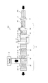
まず、図1及び図2を参照して、本発明の第1実施形態に係る板ガラスの製造設備100について説明する。図1は、本実施形態に係る製造設備100の要部を示した概略平面図である。図中、板ガラス101は送りローラー等によって紙面右から左へと搬送される。図のAからHの符号を付した板ガラス101は、時間の経過に伴う板ガラス101の向き及び位置を示している。以下では、図中においてAからHまでの符号を付した板ガラス101の位置を例えば「位置A」などと称して説明する。また、本実施形態の板ガラス101は、製造ラインの上流側に位置する溶解炉(図示せず)から送り出されるようにして成形されており、「成形方向」を有している。板ガラス101は長方形状(矩形状)に形成されているが、その長辺と成形方向が平行の関係にある。図1に示すように、本実施形態に係る製造設備100は、清掃ユニット10と、検査ユニット20と、を備えている。(First embodiment)
First, with reference to FIG.1 and FIG.2, the
清掃ユニット10は、通過する板ガラス101を清掃するユニットである。清掃ユニット10へは、板ガラス101が図示しない前工程において任意の大きさに切断された後に搬入される。清掃ユニット10では、板ガラス101を切断した際に付着した切り粉等を除去し、下流側に位置する検査ユニット20へと板ガラス101を搬送する。また、本実施形態では、清掃ユニット10には、板ガラス101が成形方向に搬入される。つまり、板ガラス101は、長辺と搬入方向とが一致するようにして清掃ユニット10に搬入される。
The
また、清掃ユニット10は、通過する板ガラス101に空気を吹き付ける吹出口11を有している。図1において、板ガラス101が位置Aから位置Bへと移動する際にこの吹出口11を通過する。吹出口11は、板ガラス101の搬送方向に直交する方向に延びるのではなく、搬送方向に直交する方向に対して傾斜する方向に延びている。かかる構成によれば、板ガラス101が吹出口11にさしかかったところで空気の力が板ガラス101に一気に加わるのを防ぎ、板ガラス101に空気の力を緩やかに加えることができる。そのため、板ガラス101が吹出口11を通過する際に生じ得る板ガラス101の鉛直方向のばたつきを防止することができる。
Moreover, the
検査ユニット20は、板ガラス101を下流へ搬送しながら検査するユニットである。図1では、板ガラス101は位置Bから位置Hへ移動する間に検査ユニット20によって検査が行われる。本実施形態では、板ガラス101は上述した清掃ユニット10から回転することなくそのまま検査ユニット20へと搬入される。つまり、板ガラス101は成形方向と搬送方向が一致するようにして検査ユニット20へと搬送される。また、図1に示すように、検査ユニット20は、平行エッジ検査装置30と、回転装置40と、直交エッジ検査装置50と、面検査装置60と、線上検査装置70と、高速応力測定装置80と、オフライン検査装置90と、を備えている。これらの装置は、オフライン検査装置90を除き直線上に配置されている。
The
平行エッジ検査装置30は、通過する板ガラス101のうち成形方向に延びる辺(長辺)の欠陥の有無を検査する装置である。平行エッジ検査装置30は、2台のCCDカメラ31を有している。各CCDカメラ31は、板ガラス101の上方であって、板ガラス101の両長辺に対応する位置に配置されている。このCCDカメラ31により、板ガラス101が位置Bから位置Cに移動する際に、板ガラス101の長辺が撮影される。そして、平行エッジ検査装置30は、CCDカメラ31の撮影によって得た画像データに基づいて、長辺に欠陥(欠け、ひび、研削ムラ、及び汚れ)が無いか判断する。また、画像データにより板ガラス101の長辺の位置が測定できるため、この長辺の位置に基づいて一方の長辺から他方の長辺までの距離、すなわち短辺の寸法を算出ることができる。なお、検査品質向上のため、板ガラス101の上方、下方、側方の3箇所にCCDカメラ31を同時に設置してもよい。
The parallel
回転装置40は、板ガラス101を水平に回転させる装置である。本実施形態では、板ガラス101を90度回転させ、長辺が搬送方向に直交するようにする。これにより、回転装置40よりも下流側では、板ガラス101は成形方向と直交する方向に搬送される。回転装置40は、本実施形態では吸盤を有するアーム41で板ガラス101を位置Cで吸着して持ち上げ、回転させた後に位置Dに降ろす。ただし、回転装置40の具体的な構成はこれに限定されず、いかなる方法で回転させてもよい。
The
ここで、回転装置40の位置を基準とすると、検査ユニット20を構成する各装置の配列は次のようになる。すなわち、回転装置40の上流側には、平行エッジ検査装置30が配置されている。また、回転装置40の下流側には、直交エッジ検査装置50、面検査装置60、線上検査装置70、及び高速応力測定装置80が配置されている。なお、高速応力測定装置80の位置は特に限定されない。また、直交エッジ検査装置50、面検査装置60、及び線上検査装置70は、回転装置40の下流側に位置していればよく、これら3つの装置の位置は入れ替えてもよい。
Here, when the position of the
直交エッジ検査装置50は、通過する板ガラス101の成形方向に直交する辺(短辺)の欠陥の有無を検査する装置である。直交エッジ検査装置50は、2台のCCDカメラ51を有している。CCDカメラ51は、板ガラス101の上方であって、板ガラス101の短辺に対応する位置に配置されている。このCCDカメラ51により、板ガラス101が位置Dから位置Eに移動する際に、板ガラス101の短辺が撮影される。そして、撮影によって得た画像データに基づいて、短辺に欠陥が無いか判断する。また、画像データにより板ガラス101の短辺の位置が測定できるため、この短辺の位置に基づいて一方の短辺から他方の短辺までの距離、すなわち長辺の寸法もあわせて算出する。なお、検査品質向上のため、板ガラス101の上方、下方、側方の3箇所にCCDカメラ51を同時に設置してもよい。
The orthogonal
面検査装置60は、通過する板ガラス101の全面を検査する装置である。面検査装置60は、複数のCCDカメラ61を有している。CCDカメラ61は、板ガラス101の上方であって、搬送方向に直交する方向に並べて配置されている。これらのCCDカメラ61により、板ガラス101が位置Eから位置Fに移動する際に、板ガラス101の全面が撮影される。そして、撮影によって得た画像データに基づいて、板ガラス101の表面の欠陥(傷、異物の付着)及び内部の欠陥(泡、異物の混入)が無いか判断する。なお、板ガラス101の表面の傷は、成形方向に延びるようにして形成されやすい。そのため、成形方向に直交する方向に向かって表面を観測することで、傷があった場合には画像データに変化が生じやすくなり、傷を検出しやすい。つまり、かかる構成によれば、表面の検査精度を向上させることができる。
The
線上検査装置70は、通過する板ガラス101の面を成形方向に直交する線上に(成形方向に直交する方向に相対的に移動しながら)検査する装置である。線上検査装置70は、厚さ測定センサ71と、脈理検査センサ72とを有している。厚さ測定センサ71は、板ガラス101の上方から照射されて、板ガラス101の上面及び下面に反射した光を観測する。線上検査装置70は、この観測結果に基づいて、検査位置における板ガラス101の厚さを測定することができる。また、脈理検査センサ72は、板ガラス101内を通過した光を観測する。線上検査装置70は、この観測結果に基づいて、板ガラス101内の脈理を検出することができる。図1では、板ガラス101が位置Fから位置Gに移動する際に、板ガラス101の厚さが測定されるとともに脈理の有無が検査される。ここで、成形方向を有する板ガラス101は、成形方向に対して直交する方向に厚みの変化が生じやすい。また、脈理は成形方向に延びるように形成される。そのため、本実施形態のように成形方向に直交する方向へ相対的に移動しながら厚みや脈理を検査することで、板ガラスの異常な厚みや脈理を精度よく検出することができる。
The on-
高速応力測定装置80は、板ガラス101内における残留応力を高速で測定する装置である。高速応力測定装置80は、複数の応力測定センサ81を有している。応力測定センサ81は、板ガラス101の上方であって、搬送方向に直交する方向に並べて配置されている。高速応力測定装置80は、板ガラス101の下方に位置する発光部(図示せず)を有している。発光部は、板ガラス101の下面に向かってレーザー光を照射する。レーザー光は、この板ガラス101内を通過し、応力測定センサ81で受光される。そして、高速応力測定装置80は、応力測定センサ81に入射するレーザー光の角度に基づいて残留応力を算出する。図1では、板ガラスが位置Gから位置Hへ移動する際に、その板ガラス101の残留応力が測定される。通常、残留応力を精度よく測定するには比較的時間がかかるが、本実施形態の高速応力測定装置80では、応力測定センサ81及び発光部を複数配置するとともに、測定数を減らすことにより測定の高速化を実現している。
The high-speed
オフライン検査装置90は、製造ラインから取り出された板ガラス101の検査を行う装置である。板ガラス101の取り出しは、自動で行ってもよく手動で行ってもよい。なお、本実施形態では、オフライン検査装置90で検査する板ガラス101は、位置Gから取り出すように構成されている。本実施形態のオフライン検査装置90では、板ガラス101に生じる残留応力の測定と板厚の測定を同時に行う。ここで、図2はオフライン検査装置90の概略斜視図である。オフライン検査装置90ではその上に板ガラス101を載せて検査を行うが、以下では、この板ガラスの長辺に平行な方向(紙面右上・左下方向)を「X方向」とし、板ガラス101の短辺に平行な方向(紙面左上・右下方向)を「Y方向」とする。
The off-
図2に示すように、オフライン検査装置90は、テーブル91と、駆動部92と、板厚センサ93と、応力測定センサ94とを有している。テーブル91は、板ガラス101を水平に載せる台であって、X方向にスライドできるように構成されている。また、テーブル91には表面に対して垂直な方向に貫通する貫通孔(図示せず)が規則的に複数形成されている。テーブル91の下方には発光部(図示せず)が配置されており、この発光部からレーザー光が発せられると、レーザー光は貫通孔を通って板ガラス101へ照射される。駆動部92は、テーブル91の上方に位置し、Y方向に延びるレール95に沿ってY方向に駆動する。駆動部92には、板厚センサ93及び応力測定センサ94が設けられている。つまり、板厚センサ93及び応力測定センサ94は、隣接して配置されており、駆動部92とともにY方向に同時に移動するよう構成されている。なお、応力測定センサ94のY方向の移動に伴って、前述した発光部もY方向に移動する。
As shown in FIG. 2, the off-
板厚センサ93は、板ガラス101の反りを検査することができ、板ガラス101に反射した光を受光する。そして、板厚センサ93が受光した光の角度に基づいて、板ガラス101の反りを検出する。さらに、この検出データから、板ガラス101の板厚を算出することができる。応力測定センサ94は、上述した高速応力測定装置80の応力測定センサ81と基本的には同じである。ただし、オフライン検査装置90の応力測定センサ94は、高速応力測定装置80の応力測定センサ81よりも検出精度が高い。さらに、本実施形態では、応力測定センサ94で受光した発光部からのレーザー光の角度だけではなく、板厚センサ93が算出した実際の板ガラス101の板厚に基づいて、残留応力を算出(測定)している。
The
例えば、応力測定センサ94が受光するレーザー光の角度が同じであったとしても、板ガラス101の板厚が異なれば残留応力は同じではない。つまり、正確な残留応力の測定には、板ガラス101の板厚の情報が必要である。ところが、従来は、板ガラス101の残留応力を測定する装置は、板ガラス101の板厚の測定が可能な装置から独立して設けられていた。そのため、残留応力は、板ガラス101の板厚が一定であると仮定して算出され、その結果、10%程度の誤差が生じていた。これに対し、本実施形態のオフライン検査装置90は、板厚センサ93及び応力測定センサ94の両方を備えているため、実際の板ガラス101の板厚に基づいて残留応力を算出することができ、その結果、高い精度をもって残留応力の測定が可能となり、品質管理も容易となる。
For example, even if the angle of the laser beam received by the
以上の構成を備えたオフライン検査装置90は、次のように板ガラス101の検査を行う。まず、テーブル91のX方向位置を調整し、板厚センサ93及び応力測定センサ94が板ガラス101の一方の短辺付近を測定できるようにする。次に、テーブル91の位置を固定したまま、駆動部92を板ガラス101の一方の長辺から他方の長辺までY方向に少しずつ位置を変え、板ガラス101の板厚測定及び応力測定を行う。そして、駆動部92が板ガラス101の他方の長辺にまで達すると、今度はテーブル91をX方向にわずかに移動させ、同じようにして板ガラス101の他方の長辺から一方の長辺まで駆動部92の位置を少しずつ変えながら板厚測定と応力測定を行う。以上の作業を繰り返し、板ガラス101の全体にわたって検査を行ったところでオフライン検査は終了する。なお、板厚測定と応力測定は、精度よく行うといずれも比較的時間がかかるが、本実施形態のオフライン検査装置90では、これらの検査を同時に行うことができるため、測定時間が短くなる上、非常に高精度かつ効率的である。
The off-
以上が本実施形態に係る板ガラスの製造設備100の説明である。本実施形態の検査ユニット20は、成形方向と直交する方向から検査を行うと高い精度で欠陥を検出することができる面検査装置60及び線上検査装置70を備えている。そして、これらの装置は、回転装置40の下流に集めて配置されているため、板ガラス101の方向転換を繰り返す必要もなく、効率よく検査を行うことができる。なお、本実施形態では、検査ユニット20が高速応力測定装置80を備えているが、オフライン検査装置90でも板ガラス101の残留応力を測定できるため、検査ユニット20はオフライン検査装置90を備えていなくてもよい。
The above is the description of the plate
(第2実施形態)
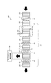
次に、図3を参照して、本発明の第2実施形態に係る板ガラス101の製造設備200について説明する。図3は、本実施形態に係る製造設備200の要部を示した概略平面図である。本実施形態と第1実施形態を対比すると、本実施形態に係る製造設備200は、板ガラス101の搬入方向、及び、検査ユニット20を構成する装置の配置順の点において、第1実施形態に係る製造設備100と異なる。それ以外の点については、両設備は基本的に同じ構成を有している。(Second Embodiment)
Next, with reference to FIG. 3, the
具体的には、本実施形態において、清掃ユニット10及び検査ユニット20には、成形方向と直交する方向で板ガラス101が搬入されている。また、検査ユニット20を構成する装置の配置順は、回転装置40を基準とすると次のようになる。つまり、回転装置40の上流側には、直交エッジ検査装置50、面検査装置60、及び線上検査装置70が配置されている。また、回転装置40の下流側には、平行エッジ検査装置30、及び高速応力測定装置80が配置されている。このように、本実施形態の場合には、面検査装置60及び線上検査装置70等を回転装置40の上流に集めて配置しているため、第1実施形態の場合と同様に、板ガラス101の方向転換を繰り返す必要もなく、高い精度の検査を効率よく行うことができる。
Specifically, in the present embodiment, the
(第3実施形態)
次に、図4を参照して、本発明の第3実施形態に係る板ガラス101の製造設備300について説明する。図4は、本実施形態に係る製造設備300の要部を示した概略平面図である。本実施形態と第1実施形態を対比すると、本実施形態に係る製造設備300は、検査ユニット20が平行エッジ検査装置30及び直交エッジ検査装置50を備えておらず、これらに代えて全エッジ検査装置35を備えている点で、第1実施形態に係る製造設備100と構成が異なる。それ以外の点については、両設備は基本的に同じ構成を有している。そのため、ここでは全エッジ検査装置35を中心に説明する。(Third embodiment)
Next, with reference to FIG. 4, the
本実施形態の全エッジ検査装置35は、板ガラス101の四辺を検査する装置である。全エッジ検査装置35は、4台のCCDカメラ36を有している。各CCDカメラ36は、板ガラス101の上方に位置し、それぞれ板ガラス101の四辺に対応する位置に配置されている。全エッジ検査装置35に搬入された板ガラス101は送りが一旦停止され、その状態で各CCDカメラ36が対応する辺に沿って移動する。そして、各CCDカメラ36が対応する辺に沿って移動する間に、その辺を撮影する。そして、全エッジ検査装置35は、各CCDカメラ36の撮影によって得た画像データに基づいて、各辺に欠陥が無いか判断する。なお、以上では全エッジ検査装置35が4台のCCDカメラ36を有している場合について説明したが、このような構成に限られない。例えば、CCDカメラ36を1台とし、板ガラス101の四辺全てに沿って移動するように構成してもよい。なお、検査品質向上のため、板ガラス101の各辺の上方、下方、側方の3箇所にCCDカメラ36を同時に設置してもよい。
The all
また、画像データにより板ガラス101の短辺及び長辺の位置が測定でき、これらの測定結果に基づいて、板ガラス101の長辺の寸法及び短辺の寸法を算出することができる。なお、本実施形態では、全エッジ検査装置35は、回転装置40の下流側に配置されているが、回転装置40の上流側に配置されていてもよい。本実施形態では、平行エッジ検査装置30及び直交エッジ検査装置50に代えて全エッジ検査装置35が採用されているが、面検査装置60及び線上検査装置70が回転装置40の下流側に集めて配置されていることに変わりなく、本実施形態の場合であっても板ガラス101を効率よく検査することができる。
Further, the position of the short side and the long side of the
(第4実施形態)
次に、図5を参照して、本発明の第4実施形態に係る板ガラス101の製造設備400について説明する。図5は、本実施形態に係る製造設備400の要部を示した概略平面図ある。本実施形態と第2実施形態を対比すると、本実施形態に係る製造設備400は、検査ユニット20が平行エッジ検査装置30及び直交エッジ検査装置50を備えておらず、これらに代えて全エッジ検査装置35を備えており、さらに、回転装置40を備えていない点で、第2実施形態に係る製造設備200と構成が異なる。それ以外の点については、両設備は基本的に同じ構成を有している。(Fourth embodiment)
Next, with reference to FIG. 5, the
なお、本実施形態の全エッジ検査装置35は、第3実施形態で説明した全エッジ検査装置35と同じである。本実施形態では、板ガラス101が成形方向と直交する方向で検査ユニット20に搬入されるため、板ガラス101を回転して向きを変えなくとも、面検査装置60及び線上検査装置70で精度のよい検査が可能である。そのため、本実施形態の検査ユニット20では、回転装置40を省略することができる。本実施形態の場合も面検査装置60及び線上検査装置70が集めて配置されており、他の実施形態と同様に、板ガラス101を効率よく検査することができる。
Note that the all-
以上、本発明の実施形態について図を参照して説明したが、具体的な構成はこれらの実施形態に限られるものではなく、この発明の要旨を逸脱しない範囲の設計の変更等があっても本発明に含まれる。 As described above, the embodiments of the present invention have been described with reference to the drawings. However, the specific configuration is not limited to these embodiments, and even if there is a design change or the like without departing from the gist of the present invention. It is included in the present invention.
本発明によれば、成形方向を有する板ガラスの検査を効率よく行うことができる検査ユニットを提供することができる。よって、本発明は、検査ユニットを含む板ガラスの製造設備の技術分野において有益である。 ADVANTAGE OF THE INVENTION According to this invention, the test | inspection unit which can test | inspect efficiently the plate glass which has a shaping | molding direction can be provided. Therefore, this invention is useful in the technical field of the manufacturing equipment of the plate glass containing an inspection unit.
10 清掃ユニット
11 吹出口
20 検査ユニット
30 平行エッジ検査装置
35 全エッジ検査装置
40 回転装置
50 直交エッジ検査装置
60 面検査装置
70 線上検査装置
71 厚さ測定センサ
72 脈理検査センサ
80 高速応力測定装置
81 応力測定センサ
90 オフライン検査装置
92 駆動部
93 板厚センサ
94 応力測定センサ
100、200、300、400 製造設備DESCRIPTION OF
Claims (6)
通過する前記板ガラスの成形方向に延びる辺を検査する平行エッジ検査装置と、
成形方向が搬送方向に直交するよう又は成形方向が搬送方向となるよう前記板ガラスを回転させる回転装置と、
通過する前記板ガラスの成形方向に直交する辺を検査する直交エッジ検査装置と、
通過する前記板ガラスの全面を検査する面検査装置と、
通過する前記板ガラスの面を成形方向に直交する線上に検査する線上検査装置と、を備え、
前記回転装置を基準にして、その上流及び下流のうち、一方側には前記平行エッジ検査装置が配置され、他方側には前記直交エッジ検査装置、前記面検査装置、及び前記線上検査装置が配置されており、
オフライン検査装置をさらに備え、
前記オフライン検査装置は、
板ガラスの板厚を測定するための板厚センサと、
板ガラスの残留応力を測定するための応力測定センサと、
板ガラスに対して平行に移動する駆動部と、を有し、
前記板厚センサ及び前記応力測定センサは、いずれも前記駆動部に設けられて同時に移動する、検査ユニット。 An inspection unit for inspecting a rectangular plate glass having a forming direction while sending it downstream,
A parallel edge inspection device for inspecting a side extending in the molding direction of the plate glass passing through;
A rotating device that rotates the plate glass so that the forming direction is orthogonal to the conveying direction or the forming direction is the conveying direction;
An orthogonal edge inspection device that inspects a side perpendicular to the molding direction of the plate glass that passes,
A surface inspection device for inspecting the entire surface of the plate glass passing through;
A line inspection device for inspecting the surface of the plate glass passing through a line perpendicular to the molding direction, and
The parallel edge inspection device is disposed on one side of the upstream and downstream sides of the rotating device, and the orthogonal edge inspection device, the surface inspection device, and the on-line inspection device are disposed on the other side. Has been
An offline inspection device,
The off-line inspection device
A plate thickness sensor for measuring the plate thickness of the plate glass;
A stress measurement sensor for measuring the residual stress of the glass sheet;
A drive unit that moves parallel to the plate glass,
The plate thickness sensor and the stress measurement sensor are both provided in the drive unit and simultaneously moved .
前記直交エッジ検査装置は、前記板ガラスの成形方向に直交する両辺の欠陥を検出するとともに、当該両辺の位置に基づいて前記板ガラスの成形方向の寸法を算出し、
前記面検査装置は、前記板ガラスの表面及び内部の欠陥を検出し、
前記線上検査装置は、前記板ガラスの厚さを測定するとともに、前記板ガラスの脈理を検出する、請求項1に記載の検査ユニット。 The parallel edge inspection device detects defects on both sides extending in the forming direction of the plate glass and calculates a dimension in a direction perpendicular to the forming direction of the plate glass based on the positions of the both sides.
The orthogonal edge inspection device detects defects on both sides orthogonal to the forming direction of the plate glass and calculates a dimension in the forming direction of the plate glass based on the positions of the both sides.
The surface inspection device detects defects on the surface and the inside of the plate glass,
The inspection unit according to claim 1, wherein the on-line inspection device measures the thickness of the plate glass and detects a striae of the plate glass.
前記検査ユニットの上流側に位置し、通過する板ガラスに空気を吹き付ける吹出口を有する清掃ユニットと、を備え、
前記吹出口は、板ガラスの搬送方向に直交する方向に対して傾斜する方向に延びている、板ガラスの製造設備。 The inspection unit according to claim 1 or 2 ,
A cleaning unit that is located on the upstream side of the inspection unit and has a blowout opening that blows air to the passing plate glass;
The said blower outlet is the manufacturing equipment of plate glass extended in the direction inclined with respect to the direction orthogonal to the conveyance direction of plate glass.
成形方向が搬送方向に直交するよう前記板ガラスを回転させる回転装置と、
送りを一端停止して前記板ガラスの四辺を検査する全エッジ検査装置と、
通過する前記板ガラスの全面を検査する面検査装置と、
通過する前記板ガラスの面を成形方向に直交する線上に検査する線上検査装置と、を備え、
前記回転装置の下流側には、前記面検査装置、及び前記線上検査装置が配置されており、
オフライン検査装置をさらに備え、
前記オフライン検査装置は、
板ガラスの板厚を測定するための板厚センサと、
板ガラスの残留応力を測定するための応力測定センサと、
板ガラスに対して平行に移動する駆動部と、を有し、
前記板厚センサ及び前記応力測定センサは、いずれも前記駆動部に設けられて同時に移動する、検査ユニット。 A rectangular unit glass plate having a molding direction is an inspection unit that carries in the molding direction and inspects it while sending it downstream.
A rotating device that rotates the glass sheet so that the forming direction is orthogonal to the conveying direction;
An all-edge inspection device for inspecting the four sides of the plate glass by stopping the feeding;
A surface inspection device for inspecting the entire surface of the plate glass passing through;
A line inspection device for inspecting the surface of the plate glass passing through a line perpendicular to the molding direction, and
Wherein the downstream side of the rotary device, the surface inspection device, and the line testing device is arranged,
An offline inspection device,
The off-line inspection device
A plate thickness sensor for measuring the plate thickness of the plate glass;
A stress measurement sensor for measuring the residual stress of the glass sheet;
A drive unit that moves parallel to the plate glass,
The plate thickness sensor and the stress measurement sensor are both provided in the drive unit and simultaneously moved .
送りを一端停止して前記板ガラスの四辺を検査する全エッジ検査装置と、
通過する前記板ガラスの全面を検査する面検査装置と、
通過する前記板ガラスの面を成形方向に直交する線上に検査する線上検査装置と、
オフライン検査装置と、を備え、
前記オフライン検査装置は、
板ガラスの板厚を測定するための板厚センサと、
板ガラスの残留応力を測定するための応力測定センサと、
板ガラスに対して平行に移動する駆動部と、を有し、
前記板厚センサ及び前記応力測定センサは、いずれも前記駆動部に設けられて同時に移動する、検査ユニット。 A rectangular plate glass having a forming direction is an inspection unit that carries in a direction orthogonal to the forming direction and inspects while sending it downstream,
An all-edge inspection device for inspecting the four sides of the plate glass by stopping the feeding;
A surface inspection device for inspecting the entire surface of the plate glass passing through;
On-line inspection device that inspects the surface of the plate glass that passes through a line perpendicular to the molding direction;
An offline inspection device ,
The off-line inspection device
A plate thickness sensor for measuring the plate thickness of the plate glass;
A stress measurement sensor for measuring the residual stress of the glass sheet;
A drive unit that moves parallel to the plate glass,
The plate thickness sensor and the stress measurement sensor are both provided in the drive unit and simultaneously moved .
前記面検査装置は、前記板ガラスの表面及び内部の欠陥を検出し、
前記線上検査装置は、前記板ガラスの厚さを測定するとともに、前記板ガラスの脈理を検出する、請求項4又は5に記載の検査ユニット。 The all-edge inspection device detects defects on the four sides of the glass sheet, calculates the dimension in the molding direction of the glass sheet, and the dimension in the direction perpendicular to the molding direction based on the position of each side,
The surface inspection device detects defects on the surface and the inside of the plate glass,
The inspection unit according to claim 4 or 5 , wherein the on-line inspection device measures a thickness of the plate glass and detects a striae of the plate glass.
Applications Claiming Priority (1)
| Application Number | Priority Date | Filing Date | Title |
|---|---|---|---|
| PCT/JP2012/005145 WO2014027375A1 (en) | 2012-08-13 | 2012-08-13 | Plate glass inspection unit and manufacturing facility |
Publications (2)
| Publication Number | Publication Date |
|---|---|
| JP5923172B2 true JP5923172B2 (en) | 2016-05-24 |
| JPWO2014027375A1 JPWO2014027375A1 (en) | 2016-07-25 |
Family
ID=49907887
Family Applications (1)
| Application Number | Title | Priority Date | Filing Date |
|---|---|---|---|
| JP2014530390A Active JP5923172B2 (en) | 2012-08-13 | 2012-08-13 | Sheet glass inspection unit and manufacturing equipment |
Country Status (6)
| Country | Link |
|---|---|
| JP (1) | JP5923172B2 (en) |
| KR (1) | KR101697216B1 (en) |
| CN (2) | CN203396363U (en) |
| IN (1) | IN2015KN00605A (en) |
| TW (1) | TWI486578B (en) |
| WO (1) | WO2014027375A1 (en) |
Cited By (1)
| Publication number | Priority date | Publication date | Assignee | Title |
|---|---|---|---|---|
| CN117553701A (en) * | 2024-01-12 | 2024-02-13 | 山东晟昌新材料有限公司 | On-line detection device and method for warping of wood board |
Families Citing this family (9)
| Publication number | Priority date | Publication date | Assignee | Title |
|---|---|---|---|---|
| IN2015KN00605A (en) * | 2012-08-13 | 2015-07-17 | Kawasaki Heavy Ind Ltd | |
| JP2017032523A (en) * | 2015-08-06 | 2017-02-09 | 株式会社オハラ | Optical glass base material defect inspection device and optical glass base material defect inspection method |
| JP6796704B2 (en) * | 2017-02-28 | 2020-12-09 | 東洋ガラス株式会社 | Container inspection device and container inspection method |
| CN109746188A (en) * | 2017-11-01 | 2019-05-14 | 湖南海擎智能科技有限责任公司 | Assembly line sheet thickness detection system |
| CN108287167A (en) * | 2018-01-04 | 2018-07-17 | 芜湖东旭光电科技有限公司 | Liquid-crystalline glasses edge detection method and device |
| CN108716935A (en) * | 2018-08-27 | 2018-10-30 | 陈富威 | Windshield detection device |
| CN109580659A (en) * | 2018-10-23 | 2019-04-05 | 彩虹(合肥)液晶玻璃有限公司 | A kind of glass inspection systems and glass producing system |
| WO2023100892A1 (en) * | 2021-12-03 | 2023-06-08 | 日本電気硝子株式会社 | Transparent body measuring method and measuring instrument, and method for producing glass plate |
| JP2023082982A (en) * | 2021-12-03 | 2023-06-15 | 日本電気硝子株式会社 | Method for manufacturing glass article |
Citations (8)
| Publication number | Priority date | Publication date | Assignee | Title |
|---|---|---|---|---|
| JPH0669824U (en) * | 1993-03-10 | 1994-09-30 | 株式会社イナックス | Surface unevenness inspection device and surface unevenness inspection system |
| JP2006220540A (en) * | 2005-02-10 | 2006-08-24 | Central Glass Co Ltd | Device and method for detecting flaw of edge face of glass plate |
| JP2006300663A (en) * | 2005-04-19 | 2006-11-02 | Asahi Glass Co Ltd | Defect detection system |
| JP2008076171A (en) * | 2006-09-20 | 2008-04-03 | Olympus Corp | Substrate inspection device |
| JP2009512839A (en) * | 2005-10-21 | 2009-03-26 | イスラ ヴィズィオーン アーゲー | Glass plate optical inspection system and method |
| JP2009222428A (en) * | 2008-03-13 | 2009-10-01 | Avanstrate Inc | Glass plate thickness measuring instrument and glass plate thickness measuring method |
| JP2010019834A (en) * | 2008-06-13 | 2010-01-28 | Nippon Electric Glass Co Ltd | Glass plate defect inspection apparatus and manufacturing method of glass plate for flat panel display |
| JP2011227049A (en) * | 2010-03-31 | 2011-11-10 | Asahi Glass Co Ltd | Method for inspecting end face of light-transmitting rectangular plate and apparatus for inspecting the end face |
Family Cites Families (11)
| Publication number | Priority date | Publication date | Assignee | Title |
|---|---|---|---|---|
| JP3746433B2 (en) * | 2001-03-02 | 2006-02-15 | 日本板硝子株式会社 | Glass product manufacturing method and manufacturing apparatus |
| JP2003098122A (en) * | 2001-09-21 | 2003-04-03 | Toshiba Ceramics Co Ltd | Visual examination device for glass board |
| WO2006108137A2 (en) * | 2005-04-06 | 2006-10-12 | Corning Incorporated | Glass inspection systems and methods for using same |
| JP4628964B2 (en) * | 2005-04-26 | 2011-02-09 | 大日本スクリーン製造株式会社 | Substrate processing equipment |
| JP2007205724A (en) | 2006-01-30 | 2007-08-16 | Central Glass Co Ltd | Shape measuring device and measuring method of glass substrate |
| WO2008072693A1 (en) * | 2006-12-14 | 2008-06-19 | Nippon Electric Glass Co., Ltd. | Glass sheet defect detection device, glass sheet manufacturing method, glass sheet, glass sheet quality judging device, and glass sheet inspection method |
| JP5596925B2 (en) | 2009-01-20 | 2014-09-24 | 株式会社山梨技術工房 | Foreign object inspection apparatus and inspection method |
| JP2012007993A (en) | 2010-06-24 | 2012-01-12 | Asahi Glass Co Ltd | Defect inspection device for plate-like transparent body and method thereof |
| CN102445168A (en) * | 2010-09-30 | 2012-05-09 | 旭硝子株式会社 | Detecting method and detecting device for surface shape |
| KR101170928B1 (en) * | 2010-11-05 | 2012-08-03 | (주)미래컴퍼니 | Substrate inspection apparatus and substrate inspection method |
| IN2015KN00605A (en) * | 2012-08-13 | 2015-07-17 | Kawasaki Heavy Ind Ltd |
-
2012
- 2012-08-13 IN IN605KON2015 patent/IN2015KN00605A/en unknown
- 2012-08-13 JP JP2014530390A patent/JP5923172B2/en active Active
- 2012-08-13 WO PCT/JP2012/005145 patent/WO2014027375A1/en active Application Filing
- 2012-08-13 KR KR1020157005839A patent/KR101697216B1/en active IP Right Grant
- 2012-11-13 TW TW101142122A patent/TWI486578B/en active
-
2013
- 2013-06-20 CN CN201320353689.7U patent/CN203396363U/en not_active Expired - Lifetime
- 2013-06-20 CN CN201310245003.7A patent/CN103591897B/en active Active
Patent Citations (8)
| Publication number | Priority date | Publication date | Assignee | Title |
|---|---|---|---|---|
| JPH0669824U (en) * | 1993-03-10 | 1994-09-30 | 株式会社イナックス | Surface unevenness inspection device and surface unevenness inspection system |
| JP2006220540A (en) * | 2005-02-10 | 2006-08-24 | Central Glass Co Ltd | Device and method for detecting flaw of edge face of glass plate |
| JP2006300663A (en) * | 2005-04-19 | 2006-11-02 | Asahi Glass Co Ltd | Defect detection system |
| JP2009512839A (en) * | 2005-10-21 | 2009-03-26 | イスラ ヴィズィオーン アーゲー | Glass plate optical inspection system and method |
| JP2008076171A (en) * | 2006-09-20 | 2008-04-03 | Olympus Corp | Substrate inspection device |
| JP2009222428A (en) * | 2008-03-13 | 2009-10-01 | Avanstrate Inc | Glass plate thickness measuring instrument and glass plate thickness measuring method |
| JP2010019834A (en) * | 2008-06-13 | 2010-01-28 | Nippon Electric Glass Co Ltd | Glass plate defect inspection apparatus and manufacturing method of glass plate for flat panel display |
| JP2011227049A (en) * | 2010-03-31 | 2011-11-10 | Asahi Glass Co Ltd | Method for inspecting end face of light-transmitting rectangular plate and apparatus for inspecting the end face |
Cited By (2)
| Publication number | Priority date | Publication date | Assignee | Title |
|---|---|---|---|---|
| CN117553701A (en) * | 2024-01-12 | 2024-02-13 | 山东晟昌新材料有限公司 | On-line detection device and method for warping of wood board |
| CN117553701B (en) * | 2024-01-12 | 2024-03-22 | 山东晟昌新材料有限公司 | On-line detection device and method for warping of wood board |
Also Published As
| Publication number | Publication date |
|---|---|
| CN203396363U (en) | 2014-01-15 |
| TW201407152A (en) | 2014-02-16 |
| CN103591897B (en) | 2016-06-29 |
| IN2015KN00605A (en) | 2015-07-17 |
| TWI486578B (en) | 2015-06-01 |
| KR20150038608A (en) | 2015-04-08 |
| JPWO2014027375A1 (en) | 2016-07-25 |
| WO2014027375A1 (en) | 2014-02-20 |
| CN103591897A (en) | 2014-02-19 |
| KR101697216B1 (en) | 2017-01-17 |
Similar Documents
| Publication | Publication Date | Title |
|---|---|---|
| JP5923172B2 (en) | Sheet glass inspection unit and manufacturing equipment | |
| TWI653450B (en) | Linear inspection system | |
| US20110136265A1 (en) | Method of Manufacturing Thin-Film Solar Panel and Laser Scribing Apparatus | |
| KR101454823B1 (en) | Visual inspection apparatus | |
| US9322786B2 (en) | Solar cell inspection apparatus and solar cell processing apparatus | |
| JP6033041B2 (en) | Automatic quality inspection device for optical glass base material and automatic quality inspection method for optical glass base material | |
| TWI393878B (en) | Panel inspection device and inspection method of panel | |
| JP2015132611A (en) | Substrate edge part inspection device | |
| JP2012073036A (en) | Glass substrate defect checkup device and glass substrate defect checkup method | |
| JP5393973B2 (en) | Rod lens array inspection apparatus and method | |
| JP2004077425A (en) | Inspecting apparatus for drive transmission belt | |
| CN108139336B (en) | Method for manufacturing glass plate | |
| KR100953203B1 (en) | Substrate quality tester | |
| JP2009236633A (en) | X-ray foreign matter inspection device | |
| KR101111065B1 (en) | Apparatus for inspecting substrate | |
| WO2020105368A1 (en) | Method for manufacturing glass plate and apparatus for manufacturing glass plate | |
| WO2013080093A1 (en) | Inspection system | |
| JP5505790B2 (en) | Inspection method using dicing machine | |
| KR101280569B1 (en) | Apparatus for inspecting substrate | |
| JP2010066242A (en) | Substrate inspection device and substrate inspection method | |
| JPH11148902A (en) | Apparatus for inspecting surface flaw of flat substrate | |
| CN211042088U (en) | Dimension measuring device for glass substrate | |
| KR101186272B1 (en) | Apparatus for inspecting substrate | |
| JP2010066241A (en) | Substrate inspection apparatus and substrate inspection method | |
| TWI503536B (en) | The method of inspecting the surface state of the flat substrate and the surface condition checking device of the flat substrate |
Legal Events
| Date | Code | Title | Description |
|---|---|---|---|
| TRDD | Decision of grant or rejection written | ||
| A01 | Written decision to grant a patent or to grant a registration (utility model) |
Free format text: JAPANESE INTERMEDIATE CODE: A01 Effective date: 20160322 |
|
| A61 | First payment of annual fees (during grant procedure) |
Free format text: JAPANESE INTERMEDIATE CODE: A61 Effective date: 20160415 |
|
| R150 | Certificate of patent or registration of utility model |
Ref document number: 5923172 Country of ref document: JP Free format text: JAPANESE INTERMEDIATE CODE: R150 |
|
| R250 | Receipt of annual fees |
Free format text: JAPANESE INTERMEDIATE CODE: R250 |