CN203396363U - Plate-shaped glass checking unit and plate-shaped glass manufacturing apparatus - Google Patents
Plate-shaped glass checking unit and plate-shaped glass manufacturing apparatus Download PDFInfo
- Publication number
- CN203396363U CN203396363U CN201320353689.7U CN201320353689U CN203396363U CN 203396363 U CN203396363 U CN 203396363U CN 201320353689 U CN201320353689 U CN 201320353689U CN 203396363 U CN203396363 U CN 203396363U
- Authority
- CN
- China
- Prior art keywords
- plate glass
- testing fixture
- forming direction
- inspection unit
- described plate
- Prior art date
- Legal status (The legal status is an assumption and is not a legal conclusion. Google has not performed a legal analysis and makes no representation as to the accuracy of the status listed.)
- Expired - Lifetime
Links
Images


Classifications
-
- G—PHYSICS
- G01—MEASURING; TESTING
- G01N—INVESTIGATING OR ANALYSING MATERIALS BY DETERMINING THEIR CHEMICAL OR PHYSICAL PROPERTIES
- G01N21/00—Investigating or analysing materials by the use of optical means, i.e. using sub-millimetre waves, infrared, visible or ultraviolet light
- G01N21/84—Systems specially adapted for particular applications
- G01N21/88—Investigating the presence of flaws or contamination
- G01N21/89—Investigating the presence of flaws or contamination in moving material, e.g. running paper or textiles
- G01N21/892—Investigating the presence of flaws or contamination in moving material, e.g. running paper or textiles characterised by the flaw, defect or object feature examined
- G01N21/896—Optical defects in or on transparent materials, e.g. distortion, surface flaws in conveyed flat sheet or rod
-
- G—PHYSICS
- G01—MEASURING; TESTING
- G01N—INVESTIGATING OR ANALYSING MATERIALS BY DETERMINING THEIR CHEMICAL OR PHYSICAL PROPERTIES
- G01N21/00—Investigating or analysing materials by the use of optical means, i.e. using sub-millimetre waves, infrared, visible or ultraviolet light
- G01N21/84—Systems specially adapted for particular applications
- G01N21/88—Investigating the presence of flaws or contamination
- G01N21/95—Investigating the presence of flaws or contamination characterised by the material or shape of the object to be examined
- G01N21/958—Inspecting transparent materials or objects, e.g. windscreens
Abstract
The utility model provides a plate-shaped glass checking unit capable of high-efficient checking of plate-shaped glass with a molding direction, and a plate-shaped glass manufacturing apparatus. According to the utility model, the checking unit (20) of the manufacturing apparatus (100) is a checking unit which performs checking at the time when transmitting downstream the plate-shaped glass (101) with the molding direction. By taking a rotation device (40) as a reference, for rotation device downstream side and rotation device upstream side, a parallel edge checking device (30) is configured at one side, and an orthogonal edge checking device (50), a surface checking device (60) and a line checking device (70) are configured at the other side.
Description
Technical field
The utility model relates to the inspection unit of the plate glass on manufacturing line, plate glass being checked.Again, the manufacturing equipment that relates to the plate glass that has comprised this inspection unit.
Background technology
Plate glass will be accepted various inspections after manufacture, and just can carry out shipment after determining the standard that has reached certain.About plate glass inspection aspect, for example, in patent documentation 1, disclose " shape measuring apparatus of glass substrate and assay method ", in patent documentation 2, disclose " foreign body detecting device and inspection method ", in patent documentation 3, disclose " flaw detection apparatus of the tabular transparent body and method thereof ", in patent documentation 4, disclose " the end face inspection method of light transmission rectangular-shaped piece and end face testing fixture ".As implied above, the apparatus and method that plate glass is checked etc. have been disclosed in more document.
Prior art document:
Patent documentation 1: TOHKEMY 2007-205724 communique;
Patent documentation 2: TOHKEMY 2010-169453 communique;
Patent documentation 3: TOHKEMY 2012-007993 communique;
Patent documentation 4: TOHKEMY 2011-227049 communique.
Utility model content
The problem that utility model will solve:
Yet any one being recorded in the technology in document is all one that is only conceived in a plurality of inspection items, how relevant apparatus and method of carrying out various inspections etc. combine in this point was not but done fully and inquired into.Furtherly, in the literature even just can all not have to record by effective related Revelation with each device of which kind of baseline configuration.At this, what inventor had in mind is the plate glass with " forming direction ", on manufacturing line, with certain direction, send the also plate glass of moulding, the directivity (directive property) having in the defects such as striped (the optical heterogeneous body part of striated or stratiform in being present in optical glass), scuffing.
The utility model is formed in view of the above problems, and being provides that to having the plate glass of forming direction, to carry out the inspection unit of high-level efficiency inspection be object.
The means of dealing with problems:
It according to the inspection unit of a form of the present utility model, is the inspection unit checking when transmitting downstream the rectangular-shaped plate glass with forming direction, wherein, this inspection unit possesses: the parallel edge testing fixture that checks the limit of extending of the described plate glass passing through on forming direction; Make described plate glass rotation so that the whirligig of forming direction and carrying direction quadrature; Check the orthogonal edges testing fixture on described plate glass and limit forming direction quadrature of passing through; Check the face testing fixture on the whole surface of the described plate glass passing through; On the line with forming direction quadrature, check the surperficial ray detection device of passed through described plate glass; Take described whirligig as benchmark, at its upstream and in downstream, in a side, dispose described parallel edge testing fixture, at opposite side, dispose described orthogonal edges testing fixture, described testing fixture and described ray detection device.
At this, the plate glass with forming direction easily scratches on forming direction, the defect of striped etc.Therefore,, if face testing fixture and ray detection device carry out the inspection of plate glass with the direction with forming direction quadrature, just can carry out high precision inspection.And, according to said structure, owing to these two testing fixtures being intensively configured in to downstream or the upstream of whirligig, thus can change without the direction that repeats plate glass, thus carry out expeditiously high-precision inspection.
In addition, in above-mentioned inspection unit, also can be the defect that described parallel edge testing fixture forms the Liang Ge limit of extending on forming direction that detects described plate glass, simultaneously the position calculation based on Gai Liangge limit goes out the structure of the size in described plate glass and direction forming direction quadrature; Described orthogonal edges testing fixture forms and detects defect described plate glass and Liang Ge limit forming direction quadrature, and simultaneously the position calculation based on Gai Liangge limit goes out the structure of the size on the forming direction of described plate glass; Described testing fixture forms the structure of the surperficial and inner defect that detects described plate glass; Described ray detection device forms the thickness of measuring described plate glass, detects the structure of the striped of described plate glass simultaneously.
In above-mentioned inspection unit, can be still to possess off-line testing fixture again; Described off-line testing fixture have plate thickness sensor for measuring the plate thickness of plate glass, for measure plate glass unrelieved stress stress determination sensor and with respect to the drive division of plate glass parallel; Described plate thickness sensor and described stress determination sensor form and are all arranged on described drive division, and mobile structure simultaneously.
If plate thickness mensuration and stress determination are carried out with high precision, can compare spended time, but according to said structure, can carry out these inspections simultaneously, therefore on the basis that the supervision time shortens, precision and efficiency are very high, and it is easy that the quality management of plate glass also becomes.
In addition according to the manufacturing equipment of plate glass of the present utility model, possess: above-mentioned inspection unit; And the upstream side that is positioned at described inspection unit, there is the cleaning unit to the blow-off outlet of passed through plate glass blow out air; Described blow-off outlet is upwardly extending in the side of the direction inclination of the carrying direction quadrature with respect to plate glass.
According to said structure, can prevent that the power of air when plate glass closes on blow-off outlet is applied to the situation on plate glass quickly, and can to plate glass, apply the power that air produces lentamente.Therefore the phenomenon that in the time of, can preventing that plate glass from passing through blow-off outlet, contingent plate glass is shaken in vertical direction.
According to the inspection unit of other forms of the present utility model, be that the rectangular-shaped plate glass with forming direction is moved into this forming direction, and the inspection unit checking when transmitting downstream; Wherein, this inspection unit possesses: make described plate glass rotation so that the whirligig of forming direction and carrying direction quadrature; Suspend and transmit, check the full marginal check device on the Si Ge limit of described plate glass; Check the face testing fixture on the whole surface of the described plate glass passing through; With on line with forming direction quadrature, check the surperficial ray detection device of passed through described plate glass; In the downstream of described whirligig, dispose described testing fixture and described ray detection device.
According to said structure, although replace parallel edge testing fixture and orthogonal edges testing fixture, adopt full marginal check device, but due to face testing fixture and ray detection device by centralized configuration the downstream at whirligig, therefore, even if in such cases, also can carry out high efficiency inspection to plate glass.
Again, in above-mentioned inspection unit, also can be the defect that described full marginal check device forms the Si Ge limit that detects described plate glass, simultaneously the position calculation based on each limit go out size on the forming direction of described plate glass and with the direction of forming direction quadrature on the structure of size; Described testing fixture forms the structure of the surperficial and inner defect that detects described plate glass; Described ray detection device forms the thickness of measuring described plate glass, detects the structure of the striped of described plate glass simultaneously.
According to the inspection unit of other form of the present utility model, be to move into the direction of this forming direction quadrature by the rectangular-shaped plate glass with forming direction, and the inspection unit checking when transmitting downstream, wherein, this inspection unit possesses: suspend and transmit, check the full marginal check device on the Si Ge limit of described plate glass; Check the face testing fixture on the whole surface of the described plate glass passing through; With on line with forming direction quadrature, check the surperficial ray detection device of passed through described plate glass.
Again, in above-mentioned inspection unit, also can be the defect that described full marginal check device forms the Si Ge limit that detects described plate glass, simultaneously the position calculation based on each limit go out size on the forming direction of described plate glass and with the direction of forming direction quadrature on the structure of size; Described testing fixture forms the structure of the surperficial and inner defect that detects described plate glass; Described ray detection device forms the thickness of measuring described plate glass, detects the structure of the striped of described plate glass simultaneously.
The effect of utility model
As mentioned above, according to the utility model, can provide a kind of inspection unit, this inspection unit can be carried out expeditiously to having the inspection of the plate glass of forming direction.
Accompanying drawing explanation
Fig. 1 is the approximate vertical view illustrating according to the major part of the manufacturing equipment of the utility model the 1st example;
Fig. 2 is the approximate three-dimensional map of the off-line testing fixture shown in Fig. 1;
Fig. 3 is the approximate vertical view illustrating according to the major part of the manufacturing equipment of the utility model the 2nd example;
Fig. 4 is the approximate vertical view illustrating according to the major part of the manufacturing equipment of the utility model the 3rd example;
Fig. 5 is the approximate vertical view illustrating according to the major part of the manufacturing equipment of the utility model the 4th example;
Symbol description:
10 cleaning units;
11 blow-off outlets;
20 inspection units;
30 parallel edge testing fixtures;
35 full marginal check devices;
40 whirligigs;
50 orthogonal edges testing fixtures;
60 testing fixtures;
70 ray detection devices;
71 thickness measurement sensors;
72 stripeds check sensor;
80 high speed stress determination devices;
81 stress determination sensors;
90 off-line testing fixtures;
92 drive divisions;
93 plate thickness sensors;
94 stress determination sensors;
100,200,300,400 manufacturing equipments.
Embodiment
In the time of below with reference to accompanying drawings to describing according to example of the present utility model.Below, identical or suitable key element in institute's drawings attached is marked with to identical symbol, and the repetitive description thereof will be omitted.
(the 1st example)
First, with reference to Fig. 1 and Fig. 2, illustrate according to the manufacturing equipment 100 of the plate glass of the utility model the 1st example.Fig. 1 is the approximate vertical view illustrating according to the major part of the manufacturing equipment 100 of this example.In figure plate glass 101 under the effect of feeding roller from the direction carrying left of the right of paper.In figure, be marked with A to shown in the plate glass 101 of H symbol be As time goes on plate glass 101 present towards and position.Below, in the drawings by be marked with A to the plate glass 101 position of H symbol such as being called " position A " etc. and describing.In addition, the plate glass 101 of this example is that the melting furnace (not shown) from being arranged in the upstream side of manufacturing line is sent and carries out moulding, and has " forming direction ".Though plate glass 101 forms between ,Dan Qichang limit and forming direction and exists parallel relation with rectangular shape (rectangular shape).As shown in Figure 1, according to the manufacturing equipment 100 of this example, possess cleaning unit 10 and inspection unit 20.
In addition, have a blow-off outlet 11 on cleaning unit 10, it is to passed through plate glass 101 blow out air.In Fig. 1, in the process that plate glass 101Cong position A moves to position B, will pass through this blow-off outlet 11.Blow-off outlet 11 is not upwardly extending in the side of the carrying direction quadrature with plate glass 101, but the side tilting in the direction with respect to carrying direction quadrature is upwardly extending.According to said structure, can prevent that, when plate glass 101 closes on blow-off outlet 11, the power of air is applied to the situation on plate glass 101 quickly, and can to plate glass 101, apply at leisure the power of air.Therefore the phenomenon that in the time of, can preventing plate glass 101 by blow-off outlet 11, issuable plate glass 101 is shaken in vertical direction.
Parallel edge testing fixture 30 is to check the device that whether has defect on forming direction on the limit (long limit) of extending in the plate glass 101 passing through.Parallel edge testing fixture 30 has two CCD(Charge Coupled Device; Charge-coupled image sensor) camera 31.Each CCD camera 31 is configured on plate glass 101 tops and the position corresponding with plate glass 101Liang Chang limit.At plate glass 101You position B, move in the process of position C, plate glass 101Chang limit will rely on this CCD camera 31 to take.And parallel edge testing fixture 30 judges the view data of taking gained based on CCD camera 31 and whether has defect on long limit (damaged, slight crack, grinding spot and stain).In addition, owing to can relying on view data to measure plate glass 101Chang Bian position, the position calculation that can grow according to this limit goes out the size of minor face, and Cong Yifangchang limit is to the distance on the long limit of the opposing party.Moreover, in order to improve, check on the quality, also can above plate glass 101, below, place, three of sides arranges CCD camera 31 simultaneously.
Whirligig 40 is devices that plate glass 101 is horizontally rotated.In this example, make plate glass 101 90-degree rotations, the state so that long limit and carrying direction are orthogonal.By means of this, on the position near downstream than whirligig 40, plate glass 101 is that the direction to be orthogonal with forming direction is carried.Whirligig 40 utilizes the suctorial arm 41 of tool that C place, plate glass 101 position is adsorbed, mentioned under this example, and makes to land on the D of position after its rotation.But the concrete structure of whirligig 40 is not limited in this, with any method, make its rotation can.
At this, take whirligig 40 position is benchmark, and the configuration sequence of each device that forms inspection unit 20 is as described below.That is, on the upstream side of whirligig 40, dispose parallel edge testing fixture 30.In addition, on whirligig 40 downstream, dispose orthogonal edges testing fixture 50, face testing fixture 60, ray detection device 70 and high speed stress determination device 80.In addition, the residing position of high speed stress determination device 80 is not particularly limited.Again, as long as orthogonal edges testing fixture 50, face testing fixture 60, ray detection device 70 are positioned at whirligig 40 downstream, the position of above-mentioned three devices also can exchange.
Orthogonal edges testing fixture 50 is to check the device that whether has defect on plate glass 101 and limit forming direction quadrature (minor face) of passing through.Orthogonal edges testing fixture 50 has two CCD cameras 51.CCD camera 51 is configured on plate glass 101 tops and the position corresponding with two minor faces of plate glass 101.At plate glass 101You position D, move in the process of position E, rely on this CCD camera 51 to take the minor face of plate glass 101.And, the view data based on taking gained is judged on minor face, whether have defect.Again, owing to can relying on view data to measure the minor face position of plate glass 101, therefore the position based on this minor face also calculates the size on long limit simultaneously, i.e. the distance from side's minor face to the opposing party's minor face.In addition, in order to improve, check on the quality, also can above plate glass 101, below, San Ge position, side arranges CCD camera 51 simultaneously.
High speed stress determination device 80 is to measure at a high speed the device of plate glass 101 internal residual stress.High speed stress determination device 80 has a plurality of stress determination sensors 81.Stress determination sensor 81 is positioned at plate glass 101 tops, and in the direction with carrying direction quadrature alignment arrangements.High speed stress determination device 80 has the illuminating part (not shown) that is positioned at plate glass 101 belows.Illuminating part is to plate glass 101 lower surface irradiating lasers.Behind these plate glass 101 inside of laser penetration, by stress determination sensor 81, receive light.And the angle gauge of high speed stress determination device 80 based on being incident upon the laser of stress determination sensor 81 calculated unrelieved stress.In Fig. 1, plate glass 101You position G moves in the process of position H, determines the unrelieved stress of this plate glass 101.Generally, with high-precision measuring unrelieved stress, be comparison spended time, but in the high speed stress determination device 80 of this example, configured a plurality of stress determination sensors 81 and illuminating part, reduce simultaneously and measure number of times, with this, realized the high speed of measuring.
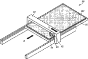
Off-line testing fixture 90 is devices that the plate glass 101 to taking out from manufacturing line checks.The mode automatic or manual that takes out plate glass 101 can.In addition, in this example, the plate glass 101 checking by off-line testing fixture 90 forms the structure that can take out from position G.In the off-line testing fixture 90 of this example, result from the mensuration of unrelieved stress and the mensuration of plate thickness of plate glass 101 simultaneously.At this, Fig. 2 is the approximate three-dimensional map of off-line testing fixture 90.In off-line testing fixture 90, plate glass 101 is placed on it and is checked, hereinafter, the direction (drawing Shang Shicong upper right to the direction of lower-left) parallel with the long limit of this plate glass is made as to " directions X "; The direction parallel with plate glass 101 minor faces (on drawing be from direction) is left to bottom right made as " Y-direction ".
As shown in Figure 2, off-line testing fixture 90 has table top 91, drive division 92, plate thickness sensor 93 and stress determination sensor 94.Table top 91 is by the table top of plate glass 101 horizontal positioned, and forms the structure that can slide towards directions X.In addition, be formed with regularly a plurality of through holes (not shown) on table top 91, the surface of their perforation direction and table top 91 is perpendicular.Below table top 91, dispose illuminating part (not shown), when launching laser from this illuminating part, this laser irradiates through through hole and to plate glass 101.Drive division 92 is positioned at the top of table top 91, along the track 95 that extends Y-direction, towards Y-direction, drives.On drive division 92, be provided with plate thickness sensor 93 and stress determination sensor 94.That is, plate thickness sensor 93 and stress determination sensor 94 disposed adjacent, and form can be together with drive division 92 towards Y-direction mobile structure simultaneously.In addition, along with stress determination sensor 94 moves towards Y-direction, above-mentioned illuminating part also moves towards Y-direction.
For example, even if the angle of the laser that stress determination sensor 94 receives is identical, if but the plate thickness of plate glass 101 is different, and unrelieved stress just can not be identical.That is,, in order to determine correct unrelieved stress, need the information of the plate thickness of plate glass 101.Yet in the past, the device of measuring the unrelieved stress of plate glass 101 was independent set from carrying out the device that the plate thickness of plate glass 101 measures.Therefore, residual stress is calculated certain in the situation that at hypothesis plate glass 101 plate thickness, and its result can produce the error of 10% left and right degree.With respect to this, the off-line testing fixture 90 of this example due to possess plate thickness sensor 93 and stress determination sensor 94 both, therefore can calculate unrelieved stress by the plate thickness based on actual plate glass 101, consequently can carry out with high precision the mensuration of unrelieved stress, and make quality management also become easy.
The off-line testing fixture 90 that possesses above structure will check plate glass 101 as described below.First, adjust table top 91 in directions X Shang position, plate thickness sensor 93 and stress determination sensor 94 can be measured near a side the minor face of plate glass 101.Then, fixing under the state of table top 91 positions, drive division 92 is little by little being changed to position to the long limit of opposite side from plate glass 101 Yi Cechang edge Y-directions, and carrying out plate thickness mensuration and the stress determination of plate glass 101.And, when drive division 92 arrives the long limit of opposite side of plate glass 101, that table top 91 is moved slightly with directions X specifically, with identical method, drive division 92 is little by little changed to position to Yi Cechang limit from the long limit of plate glass 101 opposite sides, carry out plate thickness mensuration and stress determination simultaneously.Repeat above operation, after whole plate glass 101 has been carried out checking, off-line inspection finishes.In addition, if plate thickness mensuration and stress determination will launch with high precision, any one is all comparison spended time, but in the off-line testing fixture 90 of this example, owing to can carry out these simultaneously, check, therefore shorten on the basis of minute, not only precision is high and efficiency is high.
More than to according to the explanation of the plate glass manufacturing equipment 100 of this example.Inspection unit 20 at this example has possessed face testing fixture 60 and ray detection device 70.When this stream oriented device checks from the direction with forming direction quadrature, can detect accurately defect.And these install because centralized configuration is in whirligig 40 downstream, therefore, without the direction conversion that repeats plate glass 101, can check expeditiously.In addition, in this example, although inspection unit 20 has possessed high speed stress determination device 80, owing to also measuring the unrelieved stress of plate glass 101 by off-line testing fixture 90, therefore, inspection unit 20 also can not possess off-line testing fixture 90.
(the 2nd example)
Next, with reference to Fig. 3, illustrate according to the manufacturing equipment 200 of the plate glass 101 of the utility model the 2nd example.Fig. 3 is the approximate vertical view illustrating according to the major part of the manufacturing equipment 200 of this example.When this example and the 1st example are contrasted, according to the manufacturing equipment 200 of this example plate glass 101 move into direction and form inspection unit 20 device configuration sequence aspect different from the manufacturing equipment 100 according to the 1st example.Aspect in addition, these two equipment have identical structure substantially.
Concrete is in this example, and plate glass 101 is moved into cleaning unit 10 and inspection unit 20 with the direction with forming direction quadrature.Again, the configuration sequence that forms the device of inspection unit 20 be take whirligig 40 during as benchmark as following.That is, the upstream side at whirligig 40 disposes orthogonal edges testing fixture 50, face testing fixture 60 and ray detection device 70.In whirligig 40 downstream, dispose parallel edge testing fixture 30 and high speed stress determination device 80 again.So, the in the situation that of this example, due to by centralized configuration such as face testing fixture 60 and ray detection devices 70 in whirligig 40 upstream, therefore the same with the situation of the 1st example, without the direction conversion that repeats plate glass 101, can carry out expeditiously high-precision inspection.
(the 3rd example)
Next, with reference to Fig. 4, illustrate according to the manufacturing equipment 300 of the plate glass 101 of the 3rd example of the present utility model.Fig. 4 is the approximate vertical view illustrating according to the major part of the manufacturing equipment 300 of this example.When this example is contrasted with the 1st example, according to the manufacturing equipment 300 of this example, at inspection unit 20, do not possess parallel edge testing fixture 30 and orthogonal edges testing fixture 50, and replace, possess in full marginal check device 35 this point, different from manufacturing equipment 100 structures according to the 1st example.Aspect in addition, these two equipment have identical structure substantially.Therefore, at this, will centered by full marginal check device 35, describe.
The full marginal check device 35 of this example is the device that checks plate glass 101Si Ge limit.Full marginal check device 35 has 4 CCD cameras 36.Each CCD camera 36 is positioned at the top of plate glass 101, and is configured in respectively on the position corresponding with plate glass 101Si limit.Move into and to the plate glass 101 in full marginal check device 35, temporarily stop it and transmit, each CCD camera 36 can move along each self-corresponding limit in this state.And each CCD camera 36 ,Dui Gai during moving along corresponding limit takes on limit.And the view data of full marginal check device 35 based on relying on each CCD camera 36 to take gained, judges whether there is defect on each limit.In addition, above, although illustrated that full marginal check device 35 has the situation of 4 CCD cameras 36, is not limited to such structure.For example, also can form 1 CCD camera 36 is set, and the structure that it is moved along the whole four edges of plate glass 101.In addition, in order to improve the quality of inspection, also can above plate glass 101Ge limit, below, San Ge position, side arranges CCD camera 36 simultaneously.
In addition, according to view data, can determine plate glass 101 minor face Ji Changbian positions, and based on these measurement results, can calculate the size on plate glass 101Chang limit and the size of minor face.In addition, in this example, although full marginal check device 35 is configured in whirligig 40 downstream, also can be configured in the upstream side of whirligig 40.In this example, although replace parallel edge testing fixture 30 and orthogonal edges testing fixture 50, adopt full marginal check device 35, but with face testing fixture 60 and ray detection device 70 centralized configuration in the situation in whirligig 40 downstream in the same manner, even if the in the situation that of this example, also can carry out high efficiency inspection to plate glass 101.
(the 4th example)
Next, with reference to Fig. 5, illustrate according to the manufacturing equipment 400 of the plate glass 101 of the utility model the 4th example.Fig. 5 is the approximate vertical view illustrating according to the major part of the manufacturing equipment 400 of this example.When this example is contrasted with the 2nd example, according to the manufacturing equipment 400 of this example, at inspection unit 20, do not possess parallel edge testing fixture 30 and orthogonal edges testing fixture 50, replace and possess full marginal check device 35, do not possess in addition in whirligig 40 this point different from manufacturing equipment 200 structures according to the 2nd example.In addition, these two equipment have substantially the same structure.
In addition, the full marginal check device 35 of this example is identical with the full marginal check device 35 illustrating in the 3rd example.In this example, because plate glass 101 is to move into inspection unit 20 with the direction of forming direction quadrature, therefore even if do not rotate plate glass 101 to change its direction, also can leading surface testing fixture 60 and ray detection device 70 carry out high-precision inspection.Therefore, in the inspection unit 20 of this example, can omit whirligig 40.The in the situation that of this example, be also that centralized configuration has face testing fixture 60 and ray detection device 70, and with other examples in the same manner, can check expeditiously plate glass 101.
Above with reference to the accompanying drawings of example of the present utility model, but concrete structure is not limited to these examples, and the change in the design in the scope that does not depart from the utility model purport etc. is also contained in the utility model.
Industrial applicability:
According to the utility model, can provide a kind of inspection unit, this inspection unit can carry out high efficiency inspection to having the plate glass of forming direction.Therefore, the utility model is significant in the technical field of the manufacturing equipment of the plate glass that comprises inspection unit.
Claims (8)
1. an inspection unit, is characterized in that, is the inspection unit checking when transmitting downstream the rectangular-shaped plate glass with forming direction, and this inspection unit possesses:
Check the parallel edge testing fixture on the limit of extending of the described plate glass passing through on forming direction;
Make described plate glass rotation so that the whirligig of forming direction and carrying direction quadrature;
Check the orthogonal edges testing fixture on described plate glass and limit forming direction quadrature of passing through;
Check the face testing fixture on the whole surface of the described plate glass passing through;
On the line with forming direction quadrature, check the surperficial ray detection device of passed through described plate glass,
Take described whirligig as benchmark, at its upstream and in downstream, in a side, dispose described parallel edge testing fixture, at opposite side, dispose described orthogonal edges testing fixture, described testing fixture and described ray detection device.
2. inspection unit according to claim 1, it is characterized in that, described parallel edge testing fixture forms the defect on the Liang Ge limit of extending on forming direction that detects described plate glass, and simultaneously the position calculation based on Gai Liangge limit goes out the structure of the size in described plate glass and direction forming direction quadrature;
Described orthogonal edges testing fixture forms and detects defect described plate glass and Liang Ge limit forming direction quadrature, and simultaneously the position calculation based on Gai Liangge limit goes out the structure of the size on the forming direction of described plate glass;
Described testing fixture forms the structure of the surperficial and inner defect that detects described plate glass;
Described ray detection device forms the thickness of measuring described plate glass, detects the structure of the striped of described plate glass simultaneously.
3. inspection unit according to claim 2, is characterized in that, also possesses off-line testing fixture;
Described off-line testing fixture have plate thickness sensor for measuring the plate thickness of plate glass,
For measure plate glass unrelieved stress stress determination sensor and
Drive division with respect to plate glass parallel;
Described plate thickness sensor and described stress determination sensor form and are all arranged on described drive division, and mobile structure simultaneously.
4. a manufacturing equipment for plate glass, is characterized in that, possesses:
Inspection unit according to claim 3; And
Be positioned at the upstream side of described inspection unit, there is the cleaning unit to the blow-off outlet of passed through plate glass blow out air;
Described blow-off outlet is upwardly extending in the side of the direction inclination of the carrying direction quadrature with respect to plate glass.
5. an inspection unit, is characterized in that, be the rectangular-shaped plate glass with forming direction is moved into this forming direction, and the inspection unit checking when transmitting downstream, this inspection unit possesses:
Make described plate glass rotation so that the whirligig of forming direction and carrying direction quadrature;
Suspend and transmit, check the full marginal check device on the Si Ge limit of described plate glass;
Check the face testing fixture on the whole surface of the described plate glass passing through; With
On the line with forming direction quadrature, check the surperficial ray detection device of passed through described plate glass;
In the downstream of described whirligig, dispose described testing fixture and described ray detection device.
6. inspection unit according to claim 5, is characterized in that,
Described full marginal check device forms the defect on the Si Ge limit that detects described plate glass, simultaneously the position calculation based on each limit go out size on the forming direction with described plate glass and with the direction of forming direction quadrature on the structure of size;
Described testing fixture forms the structure of the surperficial and inner defect that detects described plate glass;
Described ray detection device forms the thickness of measuring described plate glass, detects the structure of the striped of described plate glass simultaneously.
7. an inspection unit, is characterized in that, be by the rectangular-shaped plate glass with forming direction to move into the direction of this forming direction quadrature, and the inspection unit checking when transmitting downstream, this inspection unit possesses:
Suspend and transmit, check the full marginal check device on the Si Ge limit of described plate glass;
Check the face testing fixture on the whole surface of the described plate glass passing through; With
On the line with forming direction quadrature, check the surperficial ray detection device of passed through described plate glass.
8. inspection unit according to claim 7, is characterized in that,
Described full marginal check device forms the defect on the Si Ge limit that detects described plate glass, simultaneously the position calculation based on each limit go out size on the forming direction with described plate glass and with the direction of forming direction quadrature on the structure of size;
Described testing fixture forms the structure of the surperficial and inner defect that detects described plate glass;
Described ray detection device forms the thickness of measuring described plate glass, detects the structure of the striped of described plate glass simultaneously.
Applications Claiming Priority (2)
| Application Number | Priority Date | Filing Date | Title |
|---|---|---|---|
| PCT/JP2012/005145 WO2014027375A1 (en) | 2012-08-13 | 2012-08-13 | Plate glass inspection unit and manufacturing facility |
| JPPCT/JP2012/005145 | 2012-08-13 |
Publications (1)
| Publication Number | Publication Date |
|---|---|
| CN203396363U true CN203396363U (en) | 2014-01-15 |
Family
ID=49907887
Family Applications (2)
| Application Number | Title | Priority Date | Filing Date |
|---|---|---|---|
| CN201310245003.7A Active CN103591897B (en) | 2012-08-13 | 2013-06-20 | The inspection unit of plate glass and the equipment of manufacture |
| CN201320353689.7U Expired - Lifetime CN203396363U (en) | 2012-08-13 | 2013-06-20 | Plate-shaped glass checking unit and plate-shaped glass manufacturing apparatus |
Family Applications Before (1)
| Application Number | Title | Priority Date | Filing Date |
|---|---|---|---|
| CN201310245003.7A Active CN103591897B (en) | 2012-08-13 | 2013-06-20 | The inspection unit of plate glass and the equipment of manufacture |
Country Status (6)
| Country | Link |
|---|---|
| JP (1) | JP5923172B2 (en) |
| KR (1) | KR101697216B1 (en) |
| CN (2) | CN103591897B (en) |
| IN (1) | IN2015KN00605A (en) |
| TW (1) | TWI486578B (en) |
| WO (1) | WO2014027375A1 (en) |
Cited By (4)
| Publication number | Priority date | Publication date | Assignee | Title |
|---|---|---|---|---|
| CN103591897A (en) * | 2012-08-13 | 2014-02-19 | 川崎重工业株式会社 | Check unit for plate-shaped glass and manufacture equipment |
| CN108287167A (en) * | 2018-01-04 | 2018-07-17 | 芜湖东旭光电科技有限公司 | Liquid-crystalline glasses edge detection method and device |
| CN108716935A (en) * | 2018-08-27 | 2018-10-30 | 陈富威 | Windshield detection device |
| CN109580659A (en) * | 2018-10-23 | 2019-04-05 | 彩虹(合肥)液晶玻璃有限公司 | A kind of glass inspection systems and glass producing system |
Families Citing this family (7)
| Publication number | Priority date | Publication date | Assignee | Title |
|---|---|---|---|---|
| JP2017032523A (en) * | 2015-08-06 | 2017-02-09 | 株式会社オハラ | Optical glass base material defect inspection device and optical glass base material defect inspection method |
| JP6796704B2 (en) * | 2017-02-28 | 2020-12-09 | 東洋ガラス株式会社 | Container inspection device and container inspection method |
| CN109746188A (en) * | 2017-11-01 | 2019-05-14 | 湖南海擎智能科技有限责任公司 | Assembly line sheet thickness detection system |
| CN108106996A (en) * | 2017-12-25 | 2018-06-01 | 通彩智能科技集团有限公司 | A kind of glass detection holds platform |
| WO2023100892A1 (en) * | 2021-12-03 | 2023-06-08 | 日本電気硝子株式会社 | Transparent body measuring method and measuring instrument, and method for producing glass plate |
| JP2023082982A (en) * | 2021-12-03 | 2023-06-15 | 日本電気硝子株式会社 | Method for manufacturing glass article |
| CN117553701B (en) * | 2024-01-12 | 2024-03-22 | 山东晟昌新材料有限公司 | On-line detection device and method for warping of wood board |
Family Cites Families (19)
| Publication number | Priority date | Publication date | Assignee | Title |
|---|---|---|---|---|
| JP2585594Y2 (en) * | 1993-03-10 | 1998-11-18 | 株式会社イナックス | Surface unevenness inspection system |
| JP3746433B2 (en) * | 2001-03-02 | 2006-02-15 | 日本板硝子株式会社 | Glass product manufacturing method and manufacturing apparatus |
| JP2003098122A (en) * | 2001-09-21 | 2003-04-03 | Toshiba Ceramics Co Ltd | Visual examination device for glass board |
| JP4626982B2 (en) * | 2005-02-10 | 2011-02-09 | セントラル硝子株式会社 | Defect detection device and detection method for end face of glass plate |
| JP2008536127A (en) * | 2005-04-06 | 2008-09-04 | コーニング インコーポレイテッド | Glass inspection apparatus and method of use thereof |
| JP2006300663A (en) * | 2005-04-19 | 2006-11-02 | Asahi Glass Co Ltd | Defect detection system |
| JP4628964B2 (en) * | 2005-04-26 | 2011-02-09 | 大日本スクリーン製造株式会社 | Substrate processing equipment |
| DE102005050882B4 (en) * | 2005-10-21 | 2008-04-30 | Isra Vision Systems Ag | System and method for optical inspection of glass panes |
| JP2007205724A (en) | 2006-01-30 | 2007-08-16 | Central Glass Co Ltd | Shape measuring device and measuring method of glass substrate |
| JP2008076171A (en) * | 2006-09-20 | 2008-04-03 | Olympus Corp | Substrate inspection device |
| KR101475310B1 (en) * | 2006-12-14 | 2014-12-22 | 니폰 덴키 가라스 가부시키가이샤 | Glass sheet defect detection device, glass sheet manufacturing method, glass sheet, glass sheet quality judging device, and glass sheet inspection method |
| JP4964176B2 (en) * | 2008-03-13 | 2012-06-27 | AvanStrate株式会社 | Glass plate thickness measuring apparatus and glass plate thickness measuring method |
| JP2010019834A (en) * | 2008-06-13 | 2010-01-28 | Nippon Electric Glass Co Ltd | Glass plate defect inspection apparatus and manufacturing method of glass plate for flat panel display |
| JP5596925B2 (en) | 2009-01-20 | 2014-09-24 | 株式会社山梨技術工房 | Foreign object inspection apparatus and inspection method |
| JP2011227049A (en) | 2010-03-31 | 2011-11-10 | Asahi Glass Co Ltd | Method for inspecting end face of light-transmitting rectangular plate and apparatus for inspecting the end face |
| JP2012007993A (en) | 2010-06-24 | 2012-01-12 | Asahi Glass Co Ltd | Defect inspection device for plate-like transparent body and method thereof |
| CN102445168A (en) * | 2010-09-30 | 2012-05-09 | 旭硝子株式会社 | Detecting method and detecting device for surface shape |
| KR101170928B1 (en) * | 2010-11-05 | 2012-08-03 | (주)미래컴퍼니 | Substrate inspection apparatus and substrate inspection method |
| WO2014027375A1 (en) * | 2012-08-13 | 2014-02-20 | 川崎重工業株式会社 | Plate glass inspection unit and manufacturing facility |
-
2012
- 2012-08-13 WO PCT/JP2012/005145 patent/WO2014027375A1/en active Application Filing
- 2012-08-13 KR KR1020157005839A patent/KR101697216B1/en active IP Right Grant
- 2012-08-13 JP JP2014530390A patent/JP5923172B2/en active Active
- 2012-08-13 IN IN605KON2015 patent/IN2015KN00605A/en unknown
- 2012-11-13 TW TW101142122A patent/TWI486578B/en active
-
2013
- 2013-06-20 CN CN201310245003.7A patent/CN103591897B/en active Active
- 2013-06-20 CN CN201320353689.7U patent/CN203396363U/en not_active Expired - Lifetime
Cited By (5)
| Publication number | Priority date | Publication date | Assignee | Title |
|---|---|---|---|---|
| CN103591897A (en) * | 2012-08-13 | 2014-02-19 | 川崎重工业株式会社 | Check unit for plate-shaped glass and manufacture equipment |
| CN103591897B (en) * | 2012-08-13 | 2016-06-29 | 川崎重工业株式会社 | The inspection unit of plate glass and the equipment of manufacture |
| CN108287167A (en) * | 2018-01-04 | 2018-07-17 | 芜湖东旭光电科技有限公司 | Liquid-crystalline glasses edge detection method and device |
| CN108716935A (en) * | 2018-08-27 | 2018-10-30 | 陈富威 | Windshield detection device |
| CN109580659A (en) * | 2018-10-23 | 2019-04-05 | 彩虹(合肥)液晶玻璃有限公司 | A kind of glass inspection systems and glass producing system |
Also Published As
| Publication number | Publication date |
|---|---|
| CN103591897A (en) | 2014-02-19 |
| KR101697216B1 (en) | 2017-01-17 |
| KR20150038608A (en) | 2015-04-08 |
| TWI486578B (en) | 2015-06-01 |
| TW201407152A (en) | 2014-02-16 |
| CN103591897B (en) | 2016-06-29 |
| JPWO2014027375A1 (en) | 2016-07-25 |
| IN2015KN00605A (en) | 2015-07-17 |
| WO2014027375A1 (en) | 2014-02-20 |
| JP5923172B2 (en) | 2016-05-24 |
Similar Documents
| Publication | Publication Date | Title |
|---|---|---|
| CN203396363U (en) | Plate-shaped glass checking unit and plate-shaped glass manufacturing apparatus | |
| TWI726056B (en) | Shape measuring device | |
| TWI495622B (en) | On - board surface detection method and scribing device | |
| KR20190046663A (en) | Inspection system and method for analysing defects | |
| JP2012089809A (en) | Holding member posture determination device, method thereof, substrate processing device, and recording medium | |
| US9140546B2 (en) | Apparatus and method for three dimensional inspection of wafer saw marks | |
| KR101080216B1 (en) | Apparatus for inspecting glass edge and method for inspecting glass edge using thereof | |
| EP2799809B1 (en) | Method for measuring shape of threaded tube end portion | |
| CN102620651B (en) | Image measurer | |
| CN108731602A (en) | Object thickness measurement system, method, detection device and computer program product | |
| CN104777168A (en) | Apparatus for inspecting edge of substrate | |
| US10088339B2 (en) | Automated system and method for detecting defective edges of printed circuit boards and other objects using multiple sensors | |
| JP6738597B2 (en) | Method and device for determining local refractive power | |
| CN103698910A (en) | Foreign matter detection machine and detection method thereof | |
| JP2007322421A (en) | Method and device for examining end face of light guide | |
| CN103438803A (en) | Method for performing view-field-across accurate measurement on size of rectangular part through computer vision technology | |
| US8208016B2 (en) | Automated visual checking device | |
| JP6884077B2 (en) | Surface inspection equipment and surface inspection method | |
| TWI631593B (en) | Contaminant measurement substrate, and apparatus and method for fabricating substrate using the same | |
| TWM569492U (en) | Measuring device for detecting roughness and deformation of wafer ring | |
| JP2008241612A (en) | Defect inspection device and method | |
| TWM477571U (en) | Image inspection device | |
| JP2009133745A (en) | Inspection method and device | |
| JP6875243B2 (en) | Plate-shaped inspection device | |
| CN103852427A (en) | System and method for online measuring color and reflectance of glass |
Legal Events
| Date | Code | Title | Description |
|---|---|---|---|
| C14 | Grant of patent or utility model | ||
| GR01 | Patent grant | ||
| CX01 | Expiry of patent term | ||
| CX01 | Expiry of patent term |
Granted publication date: 20140115 |