WO2014024475A1 - 映像提供方法、送信装置および受信装置 - Google Patents
映像提供方法、送信装置および受信装置 Download PDFInfo
- Publication number
- WO2014024475A1 WO2014024475A1 PCT/JP2013/004742 JP2013004742W WO2014024475A1 WO 2014024475 A1 WO2014024475 A1 WO 2014024475A1 JP 2013004742 W JP2013004742 W JP 2013004742W WO 2014024475 A1 WO2014024475 A1 WO 2014024475A1
- Authority
- WO
- WIPO (PCT)
- Prior art keywords
- video
- scene
- cropping
- angle
- user
- Prior art date
Links
Images


Classifications
-
- H—ELECTRICITY
- H04—ELECTRIC COMMUNICATION TECHNIQUE
- H04N—PICTORIAL COMMUNICATION, e.g. TELEVISION
- H04N21/00—Selective content distribution, e.g. interactive television or video on demand [VOD]
- H04N21/40—Client devices specifically adapted for the reception of or interaction with content, e.g. set-top-box [STB]; Operations thereof
- H04N21/43—Processing of content or additional data, e.g. demultiplexing additional data from a digital video stream; Elementary client operations, e.g. monitoring of home network or synchronising decoder's clock; Client middleware
- H04N21/44—Processing of video elementary streams, e.g. splicing a video clip retrieved from local storage with an incoming video stream, rendering scenes according to MPEG-4 scene graphs
- H04N21/4402—Processing of video elementary streams, e.g. splicing a video clip retrieved from local storage with an incoming video stream, rendering scenes according to MPEG-4 scene graphs involving reformatting operations of video signals for household redistribution, storage or real-time display
-
- H—ELECTRICITY
- H04—ELECTRIC COMMUNICATION TECHNIQUE
- H04N—PICTORIAL COMMUNICATION, e.g. TELEVISION
- H04N21/00—Selective content distribution, e.g. interactive television or video on demand [VOD]
- H04N21/20—Servers specifically adapted for the distribution of content, e.g. VOD servers; Operations thereof
- H04N21/21—Server components or server architectures
- H04N21/218—Source of audio or video content, e.g. local disk arrays
- H04N21/21805—Source of audio or video content, e.g. local disk arrays enabling multiple viewpoints, e.g. using a plurality of cameras
-
- H—ELECTRICITY
- H04—ELECTRIC COMMUNICATION TECHNIQUE
- H04N—PICTORIAL COMMUNICATION, e.g. TELEVISION
- H04N21/00—Selective content distribution, e.g. interactive television or video on demand [VOD]
- H04N21/20—Servers specifically adapted for the distribution of content, e.g. VOD servers; Operations thereof
- H04N21/23—Processing of content or additional data; Elementary server operations; Server middleware
- H04N21/234—Processing of video elementary streams, e.g. splicing of video streams, manipulating MPEG-4 scene graphs
- H04N21/2343—Processing of video elementary streams, e.g. splicing of video streams, manipulating MPEG-4 scene graphs involving reformatting operations of video signals for distribution or compliance with end-user requests or end-user device requirements
-
- H—ELECTRICITY
- H04—ELECTRIC COMMUNICATION TECHNIQUE
- H04N—PICTORIAL COMMUNICATION, e.g. TELEVISION
- H04N21/00—Selective content distribution, e.g. interactive television or video on demand [VOD]
- H04N21/20—Servers specifically adapted for the distribution of content, e.g. VOD servers; Operations thereof
- H04N21/25—Management operations performed by the server for facilitating the content distribution or administrating data related to end-users or client devices, e.g. end-user or client device authentication, learning user preferences for recommending movies
- H04N21/258—Client or end-user data management, e.g. managing client capabilities, user preferences or demographics, processing of multiple end-users preferences to derive collaborative data
- H04N21/25866—Management of end-user data
- H04N21/25891—Management of end-user data being end-user preferences
-
- H—ELECTRICITY
- H04—ELECTRIC COMMUNICATION TECHNIQUE
- H04N—PICTORIAL COMMUNICATION, e.g. TELEVISION
- H04N21/00—Selective content distribution, e.g. interactive television or video on demand [VOD]
- H04N21/60—Network structure or processes for video distribution between server and client or between remote clients; Control signalling between clients, server and network components; Transmission of management data between server and client, e.g. sending from server to client commands for recording incoming content stream; Communication details between server and client
- H04N21/61—Network physical structure; Signal processing
- H04N21/6156—Network physical structure; Signal processing specially adapted to the upstream path of the transmission network
- H04N21/6175—Network physical structure; Signal processing specially adapted to the upstream path of the transmission network involving transmission via Internet
-
- H—ELECTRICITY
- H04—ELECTRIC COMMUNICATION TECHNIQUE
- H04N—PICTORIAL COMMUNICATION, e.g. TELEVISION
- H04N23/00—Cameras or camera modules comprising electronic image sensors; Control thereof
- H04N23/60—Control of cameras or camera modules
- H04N23/698—Control of cameras or camera modules for achieving an enlarged field of view, e.g. panoramic image capture
-
- H—ELECTRICITY
- H04—ELECTRIC COMMUNICATION TECHNIQUE
- H04N—PICTORIAL COMMUNICATION, e.g. TELEVISION
- H04N5/00—Details of television systems
- H04N5/76—Television signal recording
- H04N5/765—Interface circuits between an apparatus for recording and another apparatus
- H04N5/775—Interface circuits between an apparatus for recording and another apparatus between a recording apparatus and a television receiver
Definitions
- the present invention relates to a video providing method, a transmitting device, and a receiving device for creating, transmitting, and reproducing video content.
- Patent Document 1 discloses a server that can upload and share personal video content, and a user can select and view video content uploaded by an individual via the Internet.
- Patent Document 2 discloses a system that can upload video captured by a camera to the Internet as it is, and a user can play and enjoy live video distributed via the Internet.
- the video content distribution / viewing system by the broadcasting station and the video distribution service by the Internet cannot view the video reflecting the user's preference.
- an object of the present invention is to provide a video providing method and the like that can provide a video reflecting user's preference, in view of such problems.
- a video providing method is a video providing method for a computer to provide a video to a user, and (i) a first part of a shooting space.
- the video providing method, the transmitting device, and the receiving device of the present invention enable automatic generation of video content reflecting the user's intention, the user can enjoy the video content in a favorite way as an individual likes. It becomes possible.
- FIG. 1 is a diagram illustrating a configuration of a video content distribution / viewing system using broadcast waves.
- FIG. 2 is a diagram for explaining a usage pattern of the playback device according to the first embodiment.
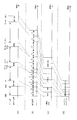
- FIG. 3 is a diagram illustrating a configuration of a digital stream in the transport stream format.
- FIG. 4 is a diagram for explaining the structure of a video stream.
- FIG. 5 is a diagram for explaining the internal configuration of the access unit of the video stream.
- FIG. 6 is a diagram for explaining cropping area information and scaling information.
- FIG. 7 is a diagram for explaining a specific designation method of cropping area information and scaling information.
- FIG. 8 is a diagram for explaining the configuration of the PES packet.
- FIG. 9 is a diagram illustrating a data structure of TS packets constituting the transport stream.
- FIG. 10 is a diagram for explaining the data structure of the PMT.
- FIG. 11 is a diagram for explaining a reference relationship of video streams.
- FIG. 12 is a diagram for explaining the structure of a source packet.
- FIG. 13 is a diagram for explaining conversion from a TS stream to a TTS stream.
- FIG. 14 is a diagram for explaining a video content distribution / viewing system that reflects personal preferences.
- FIG. 15 is a diagram for explaining a wide-angle shooting method of an event by a plurality of video shooting units.
- FIG. 16 is a diagram for explaining a wide-angle video generation method.
- FIG. 17 is a diagram for explaining a method of converting video position information into court position information.
- FIG. 18 is a diagram for explaining a video content generation method based on user preference information.
- FIG. 19 is a diagram for explaining a video cutout (cropping) method from a wide-angle video.
- FIG. 20 is a diagram for explaining a modification of the video cropping method from a wide-angle video.
- FIG. 21 is a diagram for explaining a method of generating audio data.
- FIG. 22 is a flowchart showing the flow of video providing processing performed by the editing system.
- FIG. 23 is a diagram for explaining a modification example of transmission from the video photographing unit to the editing system.
- FIG. 24 is a diagram for explaining a modification of the imaging control unit.
- FIG. 25 is a diagram for explaining an example of correction of subject position information.
- FIG. 26 is a diagram for explaining a cropping method from a wide-angle video for generating a video without a sense of incongruity.
- FIG. 26 is a diagram for explaining a cropping method from a wide-angle video for generating a video without a sense of incongruity.
- FIG. 27 is a diagram for explaining a method of deforming the size of the cropping area.
- FIG. 28 is a diagram for explaining a cropping method when a plurality of targets are set as user preference information.
- FIG. 29 is a diagram for explaining an automatic video content generation / viewing system reflecting personal preferences according to the second embodiment.
- FIG. 30 is a diagram for explaining an arrangement example of the spot video photographing units.
- FIG. 31 is a diagram for explaining an editing example by the automatic video selection editing unit.
- FIG. 32 is a diagram for explaining an editing example by the automatic video selection / editing unit using scene information.
- FIG. 33 is a diagram for explaining a method of scene separation.
- FIG. 34 is a diagram for explaining a flowchart of a scene segmentation algorithm.
- FIG. 34 is a diagram for explaining a flowchart of a scene segmentation algorithm.
- FIG. 35 is a diagram for explaining the temporal relationship of video scenes used for replay video.
- FIG. 36 is a diagram for explaining an example of video selection using a motion vector of a player by the automatic video selection / editing unit.
- FIG. 37 is a diagram for explaining an example of scene separation when the allowable delay amount is set.
- FIG. 38 is a diagram for explaining a method of performing scene division by offense and defense replacement.
- FIG. 39 is a diagram for explaining an application example 1 to which the first and second embodiments are applied.
- FIG. 40 is a diagram for explaining an application example 2 to which the present embodiment is applied.
- FIG. 41 is a diagram for describing a modification of the viewing system according to the present embodiment.
- FIG. 42 is a diagram for describing a user interface that reflects user preference data.
- FIG. 43 is a diagram for explaining Configuration 1 for displaying wide-angle video on a plurality of televisions.
- FIG. 44 is a diagram for explaining Configuration 2 for displaying wide-angle video on a plurality of televisions.
- FIG. 45 is a diagram for explaining a method for realizing highlight reproduction reflecting user preferences.
- FIG. 46 is a diagram for explaining a person recognition method using a plurality of cameras.
- FIG. 47 is a diagram for explaining a configuration having a face authentication database for each age.
- FIG. 48 is a diagram for explaining a method of distributing an electronic comic.
- the distribution / viewing system 10 includes a broadcasting system 100 that is a broadcasting station system that produces and transmits video content, and a playback device 110 that receives the video content from broadcast waves.
- a broadcasting system 100 that is a broadcasting station system that produces and transmits video content
- a playback device 110 that receives the video content from broadcast waves.
- the broadcast system 100 includes a broadcast video photographing unit 101, a broadcast video editing unit 102, and a broadcast stream creation unit 103.
- the broadcast video shooting unit 101 mainly refers to a video camera of a broadcasting station, and takes video and collects sound (hereinafter simply referred to as “video shooting”). That is, a video is generally photographed by a plurality of cameramen using the broadcast video photographing unit 101 from various angles. For example, when creating soccer content, various positions are used to shoot video from various viewpoints, such as a soccer pitch bird's-eye view, a player's zoomed-in video, and a different viewpoint video from behind the goal. Then, the cameraman performs shooting using the broadcast video shooting unit 101.
- the broadcast video editing unit 102 edits the video and audio recorded by being shot by the broadcast video shooting unit 101.
- the broadcast video editing includes selection of a scene to be broadcast among videos shot by a plurality of broadcast video shooting units 101, and image processing for overlaying graphics such as score information and subtitle information on the shot video. This is performed by the unit 102.
- Selection of a scene video to be broadcast from videos captured by a plurality of broadcast video imaging units 101 is performed by a director who specializes in scene selection. The director makes a determination according to the situation of the photographed content, and selects a scene to be used as appropriate. For example, in the soccer example, the director selects an image of a camera in which the player and the ball are well captured while watching the game situation.
- the broadcast stream creation unit 103 converts the video and audio content edited by the broadcast video editing unit 102 into a broadcast stream 104 that is a format for flowing the broadcast wave.
- the broadcast stream creation unit 103 generates a video stream by encoding with a video codec such as MPEG-2 or MPEG-4 AVC for video, and encodes with an audio codec such as AC3 or AAC for audio. Audio streams are generated and multiplexed into a single system stream such as MPEG-2 TS.
- the playback device 110 includes a tuner 111 and a broadcast stream decoding unit 112.
- the tuner 111 has a function of receiving a system stream and demodulating the received signal.
- the broadcast stream decoding unit 112 decodes the system stream.
- the broadcast stream decoding unit 112 generates a non-compressed image video by decoding a compression-encoded video stream in the system stream, outputs it to a video plane, and outputs it to a television or the like.
- the broadcast stream decoding unit 112 also decodes the audio stream compressed and encoded in the system stream, generates an uncompressed LPCM (Linear Pulse Code Modulation) state audio frame, and outputs the audio frame to a speaker such as a television.
- LPCM Linear Pulse Code Modulation
- the above is the configuration of the video content distribution / viewing system 10 using broadcast waves that has been widely spread.
- the user can view the video content created by the broadcast station, but the video content edited to reflect the user's intention is displayed. I can't enjoy it. That is, the content of the video content is determined by the intention of the cameraman who uses the broadcast video photographing unit 101 and the director who selects the video from a plurality of scenes using the broadcast video editing unit 102, and reflects the user's preference. None happen.
- a video providing method is a video providing method for a computer to provide a video to a user, and (i) a part of a shooting space. A first main image in which the first shooting space is shot; and (ii) a second space in which a second shooting space that is a part of the shooting space and includes a space other than the first space is shot.
- the video according to the preference information can be provided to the user.
- the user preference information indicates a viewing target that the user wants to view
- the video providing method further performs image recognition on the wide-angle video based on the user preference information.
- a position specifying step of specifying the position of the viewing target in the wide-angle video, and in the region calculating step, using the position of the viewing target specified in the position specifying step in the wide-angle video, An area including the viewing target may be calculated as the cropping area.
- the viewing target in the wide-angle video is captured by performing image recognition on the wide-angle video for the viewing target that is specified by the user based on the user preference information. Since the area can be specified as the cropping area, it is possible to provide the user with an image in which the object that the user wants to view is reflected.
- the region calculating step when the position of the viewing target in the wide-angle video is matched with a predetermined reference position in a cropping frame having a predetermined size for cropping the wide-angle video.
- An area specified by the cropping frame may be calculated as the cropping area.
- the cropping region is specified so that the position of the viewing target matches the reference position of the cropping frame for cropping, the video including the viewing target can be reliably used as the cropping video.
- an area specified by the cropping frame may be calculated as the cropping area.
- the video providing method further includes: each of the cropped video cropped in the cropping step and the sub-video acquired in the video acquisition step.
- a scene dividing step of dividing into a plurality of scenes based on a predetermined algorithm, and the cropped video and the sub-video for each of the plurality of scenes based on the user preference information acquired in the information acquiring step A video selecting step of selecting any of the above, and in the video providing step, One of the cropping image and the sub images that are selected in the image selection step may be provided to the user.
- a plurality of videos can be divided into a plurality of scenes, and an optimum video can be selected for each of the plurality of scenes according to the user's preference information, it is possible to provide a more suitable video for the user. .
- each of the cropped video and the sub-video when divided into the plurality of scenes, it may be divided every predetermined time apart from the predetermined algorithm.
- the processing unit related to the video providing method can be reduced, so that a plurality of videos can be processed almost in real time.
- the predetermined algorithm may be different for each type of event being performed in the shooting space.
- the predetermined algorithm is different for each event type, it is possible to perform scene division suitable for the event type.
- the state of the event is “in game” or “not in game”.
- a plurality of the cropped video and the sub-video are respectively determined at a timing when the determination result is switched from one of the “in game” and the “non-game” to the other. It may be divided into scenes.
- the scene is divided according to whether the event state is “in game” or “not in game”, so the scene can be divided appropriately.
- the “non-game” instead of selecting the “medium” scene, it may be selected from the video of the immediately preceding “in game” scene.
- each of the cropped video and the sub-video may be divided into a plurality of scenes by determining whether or not by the predetermined algorithm.
- the scene is divided according to whether the event state is “playing” or “not playing”, so the scene can be divided appropriately.
- Each of the cropped video and the sub-video may be divided into a plurality of scenes by determining the alternation of speakers using the predetermined algorithm.
- the scene is divided at the timing when the speaker changes, so the scene can be divided appropriately.
- each of the plurality of scenes divided in the scene dividing step is further based on the user preference information acquired in the information acquiring step and a predetermined evaluation index.
- the video selection step may select either the cropped video or the sub-video for each of the plurality of scenes based on the result evaluated in the evaluation step. .
- the video to be provided is selected according to the evaluation result for each of the plurality of scenes, it is possible to provide a video more suitable for the user's preference.
- the predetermined evaluation index is an image captured by a camera in which the viewing target is included in an angle of view and the distance to the viewing target is close among a plurality of cameras that have captured the video.
- An index that is highly evaluated as the scene may be included.
- the predetermined evaluation index is a camera in which the viewing target is included in an angle of view and the number of objects between the viewing target is small among a plurality of cameras that have captured a video. May include an index that is highly evaluated as the scene of the video imaged by.
- the predetermined evaluation index includes, among a plurality of cameras that have shot a video, the viewing target is included in an angle of view, and the viewing target reflected in the video has a large area.
- An index that is highly evaluated as a scene of a video shot by a camera may be included.
- the predetermined evaluation index is an image captured by a camera in which the viewing target is included in an angle of view and the distance to the viewing target is close among a plurality of cameras that have captured the video.
- the plurality of cameras that photographed the first index that is highly evaluated as the above-mentioned scene the viewing target is included in the angle of view, and the number of objects between the viewing target is small
- the second index that is highly evaluated as the video scene shot by the camera, and the viewing target of the plurality of cameras that shot the video includes the viewing target and is reflected in the video.
- a plurality of results which are evaluated by the two or more indicators for the scene, may be evaluated on the basis of the added value obtained by adding weighted by predetermined weighting that is associated with an index to the two or more.
- the user preference information input by the user may be acquired via the network with respect to an information terminal connected to the computer via the network. Good.
- the user can acquire the video reflecting the preference information by operating the information terminal at hand, the user can easily browse the video suitable for the user's preference.
- the user plays the video content received through the communication I / F using the receiving device.
- a digital television 202 will be described as an example of a receiving apparatus as shown in FIG.
- the digital television 202 is provided with a remote controller 201 as a user interface, and the user operates the digital television 202 by inputting to the remote controller 201.
- the digital television 202 displays a menu screen for reflecting user preferences.
- the digital television 202 displays a screen that allows the user to select what the video focused on is favorite for soccer. For example, when the user wants to see “ball” as the center, if the “ball” button on the menu screen is selected, an image focused on the ball is displayed as shown in FIG.
- the user can view a video centered on the ball. For example, when the user wants to view “player A” mainly, if the “player A” button is selected, an image focused on player A is displayed as shown in FIG.
- the user can view a video centering on the player A.
- MPEG-2 transport stream format Digital stream in MPEG-2 transport stream format is used for transmission on digital television broadcast waves.
- the MPEG-2 transport stream is a standard for multiplexing and transmitting various streams such as video and audio. It is standardized in ISO / IEC13818-1 and ITU-T recommendation H222.0.
- FIG. 3 is a diagram showing the structure of a digital stream in the MPEG-2 transport stream format.
- a transport stream is obtained by multiplexing a video stream, an audio stream, a subtitle stream, and the like.
- the video stream stores the main video of the program
- the audio stream stores the main audio portion and sub-audio of the program
- the subtitle stream stores the subtitle information of the program.
- the video stream is encoded and recorded using a method such as MPEG-2, MPEG-4 AVC.
- the audio stream is compressed and encoded and recorded by a method such as Dolby AC-3, MPEG-2 AAC, MPEG-4 AAC, HE-AAC.
- moving image compression coding such as MPEG-2, MPEG-4 AVC, SMPTE VC-1, etc.
- data amount is compressed using redundancy in the spatial direction and temporal direction of moving images.
- inter-picture predictive coding is used as a method of using temporal redundancy.
- inter-picture predictive coding when a certain picture is coded, a picture that is forward or backward in display time order is used as a reference picture. Then, the amount of motion from the reference picture is detected, and the amount of data is compressed by removing the redundancy in the spatial direction from the difference value between the motion compensated picture and the picture to be coded.
- FIG. 11 shows a picture reference structure of a general video stream. The arrow indicates that it is compressed by reference.
- a picture that does not have a reference picture and performs intra-picture predictive coding using only a picture to be coded is called an I picture.
- a picture is a unit of encoding that includes both a frame and a field.
- a picture that is inter-picture prediction encoded with reference to one already processed picture is called a P picture, and a picture that is inter-picture predictively encoded with reference to two already processed pictures at the same time is called a B picture.
- a picture that is referred to by other pictures in the B picture is called a Br picture.
- the frame in the case of the frame structure and the field in the field structure are referred to as a video access unit here.
- the video stream has a hierarchical structure as shown in FIG.
- the video stream is composed of a plurality of GOPs (Group of Pictures). By using this as a basic unit of the encoding process, editing of moving images and random access are possible.
- a GOP is composed of one or more video access units.
- the video access unit is a unit for storing coded data of a picture. In the frame structure, one frame is stored, and in the field structure, data of one field is stored.
- Each video access unit includes an AU identification code, a sequence header, a picture header, supplementary data, compressed picture data, padding data, a sequence end code, a stream end code, and the like.
- each data is stored in units called NAL units.
- AU identification code is a start code indicating the head of the access unit.
- the sequence header is a header that stores common information in a playback sequence composed of a plurality of video access units, and stores information such as resolution, frame rate, aspect ratio, and bit rate.
- the picture header is a header that stores information such as the coding method of the entire picture.
- the supplemental data is additional information that is not essential for decoding the compressed data, and stores, for example, closed caption character information displayed on the TV in synchronization with the video, GOP structure information, and the like.
- the compressed picture data stores compression-encoded picture data.
- the padding data stores meaningless data for formatting. For example, it is used as stuffing data for maintaining a predetermined bit rate.
- the sequence end code is data indicating the end of the reproduction sequence.
- the stream end code is data indicating the end of the bit stream.
- the contents of the AU identification code, sequence header, picture header, supplemental data, compressed picture data, padding data, sequence end code, and stream end code differ depending on the video encoding method.
- the AU identification code is AU delimiter (Access Unit Delimiter)
- the sequence header is SPS (Sequence Parameter Set)
- the picture header is PPS (Picture Parameter Set)
- the compressed picture The data corresponds to a plurality of slices
- the supplemental data corresponds to SEI (Supplemental Enhancement Information)
- the padding data corresponds to FillerData
- the sequence end code corresponds to End of Sequence
- the stream end code corresponds to End of Stream.
- the sequence header is sequence_Header, sequence_extension, group_of_picture_header, the picture header is picture_header, picture_coding_extension, the compressed picture data is in a plurality of slices, d Corresponds to sequence_end_code, respectively.
- sequence_end_code corresponds to sequence_end_code
- the sequence header may be necessary only in the video access unit at the head of the GOP and may not be present in other video access units.
- the picture header may refer to that of the previous video access unit in the code order, and there is no picture header in its own video access unit.
- the video access unit at the head of the GOP stores I picture data as compressed picture data, and always stores an AU identification code, a sequence header, a picture header, and compressed picture data. Padding data, sequence end code, and stream end code are stored. Video access units other than the head of the GOP always store the AU identification code and compressed picture data, and store supplementary data, padding data, a sequence end code, and a stream end code.
- the encoded frame area and the actual display area can be changed.
- an area to be actually displayed from the encoded frame area can be designated as a “cropping area”.
- the frame_cropping information indicates the difference between the upper line / underline / left line / right line of the cropping area and the upper line / underline / left line / right line of the encoded frame area. Specify as the left and right crop amount.
- frame_cropping_flag is set to 1, and frame_crop_top_offset / frame_crop_bottom_offset / frame_crop_left_offset / _crop_crop_right / crop_crop
- the vertical and horizontal sizes of the cropping area (display_horizontal_size of display_display_extension, display_vertical_size) and the difference information between the center of the encoded frame area and the center of the cropping area
- the cropping area can be specified using (picture_display_extension frame_center_horizontal_offset, frame_center_vertical_offset).
- scaling information indicating a scaling method when the cropping area is actually displayed on a television or the like. This is set as an aspect ratio, for example.
- the playback device uses the aspect ratio information to up-convert the cropping area for display.
- aspect ratio information (aspect_ratio_idc) is stored in the SPS as scaling information.
- the aspect ratio is specified as 4: 3.
- aspect ratio information (aspect_ratio_information) is stored in the sequence_header.
- Each stream included in the transport stream is identified by a stream identification ID called PID.
- PID stream identification ID
- the decoding apparatus can extract the target stream.
- the correspondence between the PID and the stream is stored in the descriptor of the PMT packet described later.
- FIG. 3 schematically shows how the transport stream is multiplexed.
- a video stream 501 composed of a plurality of video frames and an audio stream 504 composed of a plurality of audio frames are converted into PES packet sequences 502 and 505, respectively, and converted into TS packets 503 and 506.
- the data of the subtitle stream 507 is converted into a PES packet sequence 508 and further converted into a TS packet 509.
- the MPEG-2 transport stream 513 is configured by multiplexing these TS packets into one stream.
- FIG. 8 shows in more detail how the video stream is stored in the PES packet sequence.
- the first level in the figure shows a video frame sequence of the video stream.
- the second level shows a PES packet sequence.
- a plurality of video presentation units in a video stream are divided into pictures, B pictures, and P pictures, and are stored in the payload of the PES packet.
- Each PES packet has a PES header, and a PTS (Presentation Time-Stamp) that is a display time of a picture and a DTS (Decoding Time-Stamp) that is a decoding time of a picture are stored in the PES header.
- PTS Presentation Time-Stamp
- DTS Decoding Time-Stamp
- FIG. 9 is a diagram showing the data structure of TS packets constituting the transport stream.
- the TS packet is a 188-byte fixed-length packet composed of a 4-byte TS header, an adaptation field, and a TS payload.
- the TS header is composed of transport_priority, PID, adaptation_field_control, and the like.
- the PID is an ID for identifying a stream multiplexed in the transport stream as described above.
- the transport_priority is information for identifying the type of packet in TS packets having the same PID.
- Adaptation_field_control is information for controlling the configuration of the adaptation field and the TS payload.
- adaptation_field_control indicates the presence / absence thereof.
- adaptation_field_control is 1, only the TS payload is present, when adaptation_field_control is 2, only the adaptation field is present, and when adaptation_field_control is 3, both the TS payload and the adaptation field are present.
- the adaptation field is a storage area for storing data such as PCR and stuffing data for making the TS packet a fixed length of 188 bytes.
- a PES packet is divided and stored in the TS payload.
- TS packets included in the transport stream include PAT (Program Association Table), PMT (Program Map Table), PCR (Program Clock Reference), and the like in addition to video, audio, and subtitle streams. These packets are called PSI (Program Specific Information).
- PAT indicates what the PID of the PMT used in the transport stream is, and the PID of the PAT itself is registered as 0.
- the PMT has PID of each stream such as video / audio / subtitles included in the transport stream and stream attribute information corresponding to each PID, and has various descriptors related to the transport stream.
- the descriptor includes copy control information for instructing permission / non-permission of copying of the AV stream.
- the PCR is information on the STC time corresponding to the timing when the PCR packet is transferred to the decoder.
- FIG. 10 is a diagram for explaining the data structure of the PMT in detail.
- a PMT header describing the length of data included in the PMT is arranged at the head of the PMT. After that, a plurality of descriptors related to the transport stream are arranged.
- the copy control information described above is described as a descriptor.
- a plurality of pieces of stream information regarding each stream included in the transport stream are arranged after the descriptor.
- the stream information includes a stream descriptor in which a stream type, a stream PID, and stream attribute information (frame rate, aspect ratio, etc.) are described to identify a compression codec of the stream.
- the transport stream shown in FIG. 9 is a stream in which TS packets are arranged, and a stream generally used for a broadcast wave is in this format.
- the transport stream shown in FIG. 9 will be referred to as a TS stream.
- the transport stream shown in FIG. 12 is a stream in which source packets each having a 4-byte time stamp are arranged at the head of a 188-byte TS packet, and a stream generally transmitted by communication has this format.
- the transport stream shown in FIG. 12 is hereinafter referred to as a TTS stream.
- the first time stamp added to the TS packet is hereinafter referred to as ATS (Arrival_time_stamp), and ATS indicates the transfer start time of the TS packet to the stream decoder.
- ATS Arriv_time_stamp
- the source packets are arranged in the TTS stream as shown in FIG. 12, and the number incremented from the head of the TTS stream is called SPN (source packet number).
- a full TS is a TS stream composed of a 188-byte fixed-length TS packet sequence.
- a storage medium such as a BD-RE or HDD
- only necessary channel data is extracted from the full TS and recorded as a partial TS.
- the partial TS is a TTS stream.
- the TS stream is converted into the TTS stream, if the TS packets that are no longer necessary from the full TS are simply collected and recorded, there is no time interval information between the TS packets.
- FIG. 13 shows a method for converting a TS stream into a TTS stream, and the method is composed of TS packet filtering, an ATS adder, an ATC counter, and a high-frequency transmitter.
- the crystal resonator is a device that oscillates with high frequency accuracy by utilizing the piezoelectric effect of quartz (quartz), and in this case, oscillates a 27 Mhz clock.
- the ATC counter is a counter that ticks the ATC time axis in accordance with the crystal oscillator clock.
- the ATC counter is initialized with the ATS of the TS packet input from the data buffer, and increments the value at a frequency of 27 Mhz.
- TS packet filtering uses the EIT program information and the stream configuration information in the PMT packet program to filter only the TS packets that make up the program selected by the user and input them to the ATS appender.
- the ATS adder refers to the ATC value of the ATC counter for the 188-byte TS packet input via TS packet filtering, adds an ATS value to the head of the TS packet, and provides a 192-byte TS packet. Is generated. Since the ATS field is 4 bytes, a value from 0x0 to 0xFFFFFFFF is taken, and when the ATC value becomes a value greater than or equal to 0xFFFFFFFFFF, Wrap-around again and return to 0. In the case of Blu-ray (registered trademark), the first 2 bytes of the first 4 bytes of the TS packet are used for the copy control information, so the ATS value is 30 bits, and Wrap-around is performed with 30 bits.
- FIG. 14 shows an overview of the distribution / viewing system.
- the distribution / viewing system 1400 includes an imaging system 1410, an editing system 1420, and a playback system 1430.
- the shooting system 1410 includes a shooting control unit 1401, a plurality of video shooting units 1402, and a communication I / F 1403.
- the shooting system 1410 uses a plurality of video shooting units 1402 controlled by the shooting control unit 1401 to take an event, compress and code the shot video, and edit the compressed video through the communication I / F 1403. Transmit to.
- the video shooting unit 1402 mainly refers to a video camera, takes a video (including audio) based on the control of the shooting control unit 1401, and transmits the compressed and encoded video data to the communication I / F 1403.
- a video photographing unit one or a plurality of video photographing units exist, and the entire event is arranged so as to enter at a wide angle as shown in FIG.
- FIG. 15A shows an example of shooting a soccer game.
- the first camera 1501, the second camera 1502, and the third camera 1503, which are a plurality of video shooting units, are wide-angle so that the entire court can be seen. Placed in.
- FIG. 15B schematically shows images taken by the cameras 1501 to 1503.
- the first main video 1511 is a video shot by the first camera 1501
- the second main video 1512 is a video shot by the second camera 1502
- the third main video 1513 is a video shot by the third camera 1503.
- the video shot by the first camera 1501 is the first main video 1511 in which a part of the first shooting space in the shooting space is shot.
- the video shot by the second camera 1502 is a second main video 1512 in which a second shooting space including a space other than the first space, which is a part of the shooting space, is shot.
- the video shot by the third camera 1503 is a third main video 1513 in which a third shooting space including a space other than the first space and the second space in the shooting space is shot.
- one or a plurality of video photographing units 1402 are arranged with their orientations and positions fixed so that the entire event can be captured.
- the video photographing unit 1402 is configured by three cameras 1501 to 1503, but may be configured by a plurality of cameras, and may be configured by at least two cameras 1501 and 1502.
- the shooting control unit 1401 controls the start and stop of synchronized shooting for the plurality of video shooting units 1402.
- the imaging control unit 1401 is a tablet terminal 1504.
- the tablet terminal 1504 has a communication unit that can communicate with the first camera 1501, the second camera 1502, and the third camera 1503, which are a plurality of video photographing units 1402, wirelessly or by wire, and the like.
- the operations of the first camera 1501, the second camera 1502, and the third camera 1503 can be controlled by the application executed in the above. Specifically, the tablet terminal 1504 can instruct the first camera 1501, the second camera 1502, and the third camera 1503 to start and stop shooting.
- the tablet terminal 1504 sends a synchronization signal to the first camera 1501, the second camera 1502, and the third camera 1503 through a communication unit by wireless or wired communication.
- This synchronization signal is embedded in a stream that is captured and generated by the first camera 1501, the second camera 1502, and the third camera 1503, so that in the subsequent processing, if this synchronization signal is used, a plurality of streams are Synchronization can be achieved. That is, it is easy to determine where the frame of another stream is the same as the time of the frame of a certain stream.
- the synchronization signal may be signal information from an NTP server, for example.
- any one of the video photographing units 1402 may have the function of the photographing control unit 1401.
- the GUI for controlling the first camera 1501, the second camera 1502, and the third camera 1503 displayed on the tablet terminal 1504 is realized by an application such as HTML5 or Java (registered trademark). Also good.
- the communication I / F 1403 indicates an I / F for connecting to the Internet, for example, a router or the like.
- the video streams shot by the cameras 1501 to 1503 are transmitted to the editing system 1420 on the Internet through a router or the like as the communication I / F 1403.
- the communication I / F 1403 may be an I / F for transmission to an editing system existing on the network, and may be connected to a mobile phone network (3G, LTE, etc.), for example.
- the video shot by the video shooting unit 1402 may be stored in a local storage (memory or HDD) inside the terminal, and after shooting, the data may be uploaded to the editing system using an information terminal such as a personal computer. .
- the editing system 1420 includes a position specifying unit 1422, a video generation unit 1423, an automatic video editing unit 1424, an information acquisition unit 1425, a video providing unit 1426, and communication I / Fs 1421 and 1427.
- the editing system 1420 generates a wide-angle video from the video stream of the event shot by the shooting system 1410, identifies the position information of the subject by performing image recognition, and uses the position information and the user preference information to determine the user's position information. Generate an optimal video stream.
- the editing system 1420 is configured by a computer and functions as a transmission device that provides a video edited based on user preference information.
- the communication I / F 1421 functions as a video acquisition unit.
- the video generation unit 1423 generates a wide-angle video (panoramic video) from a plurality of video streams shot by the shooting system 1410. That is, the video generation unit 1423 generates a wide-angle video by combining the first main video 1511, the second main video 1512, and the third main video 1513, which are a plurality of video streams.
- FIG. 16 is a diagram schematically showing a specific method for generating a wide-angle image.
- FIG. 16A shows a plurality of videos shot by the shooting system 1410, which are the first main video 1511, the second main video 1512, and the third main video 1513 shown in the example of FIG.
- the first main video 1511 and the second main video 1512 include an overlap area that is an area in which the same space is captured, and the second main video 1512 and the second main video 1512
- the three main videos 1513 include an overlap area.
- the video generation unit 1423 generates a single wide-angle video as shown in FIG. 16C by superimposing overlapping areas included in the videos.
- the video generation unit 1423 performs the following processing.
- the video generation unit 1423 (1) extracts image feature points from the overlap area included in each video, and performs matching of the image feature points between the videos.
- an algorithm such as SIFT or SURF is used to extract the image feature points.
- a circled portion is a feature point, and between the first main video 1511 and the second main video 1512 of the feature point. Matching is indicated by an arrow.
- the video generation unit 1423 (2) transforms the image so that the image feature points between the videos 1511 to 1513 match.
- the first main video 1511 is reduced or reduced.
- the connection between the first main video 1511 and the second main video 1512 can be made seamless.
- a matrix such as a homography matrix can be generated from the feature points for shape transformation, and matrix transformation can be performed on the image.
- the video generation unit 1423 (3) synthesizes the transformed video into one wide-angle video.
- the overlap area portion included in each of the videos 1511 to 1513 may be blended, or one of the overlap areas may be deleted.
- Such means for generating a wide-angle image from a plurality of images is generally called “stitching” and has been widely used as a means for generating a wide-angle image, and is implemented by various software such as OpenCV. .
- the image distortion is specified by using the position, orientation information, angle-of-view parameter, etc. of each of the plurality of cameras 1501 to 1503 instead of the feature point matching.
- the videos 1511 to 1513 may be combined using
- the video generation unit 1423 When generating a wide-angle video using a plurality of videos 1511 to 1513, the video generation unit 1423 combines the above-described image synthesis with respect to three frames shot at the same timing among the plurality of videos 1511 to 1513. I do. That is, the video generation unit 1423 generates the first main video 1511, the second main video 1512, and the third main video 1513 embedded in the first main video 1511, the second main video 1512, and the third main video 1513, respectively. Based on a synchronization signal for synchronization, image synthesis is performed on each frame of the first main video 1511, the second main video 1512, and the third main video 1513 that are captured at the same timing while performing synchronization. .
- the position specifying unit 1422 analyzes and specifies the position information of the subject by performing image recognition processing on the wide-angle video generated by the video generating unit 1423 while referring to the content database.
- the “content database” stores information such as the shape of the ball, the shape of the ground, the name of the player, the position, the spine number, and the face photo.
- the position information of the ball is specified by performing pattern matching with the shape and color of the ball on the wide-angle video generated by the video generation unit 1423.
- the position information of the player is specified by performing pattern matching such as the player's face, uniform, back number, and body shape on the wide-angle video.
- the position specifying unit 1422 performs image recognition on the wide-angle video while referring to the content database based on the viewing target, so that the viewing target in the wide-angle video is displayed. Specify the position of.
- the position information of the player and the ball can be specified.
- tracking processing of an object such as a player or a ball can be realized by performing background subtraction, extracting only a moving object, and measuring the movement of the image.
- an object tracking process by image processing an optical flow or the like is well known, and is implemented by various software such as OpenCV.
- interpolation may be performed between the position information of the player immediately before the tracking is lost and the position information where the player is detected next.
- the court area may be specified, and the person position information may be converted into two-dimensional coordinate information on the court area.
- a conversion matrix such as a homography matrix is created from the correspondence between the end points of the court on the wide-angle image and the end points of the court on the two-dimensional coordinates, and the player on the wide-angle image
- the ball position information is converted into two-dimensional coordinates by applying a matrix operation. If each camera of the photographing system 1410 is a stereo camera, a wide-angle video can be generated as a stereo image and depth information can be obtained. For this reason, it becomes possible to obtain the position information of the player and the ball with higher accuracy by using the depth information.
- the “depth sensor” measures the distance to the target in units of each pixel by using a method (TOF) that irradiates the target with a laser such as infrared rays and measures the time required to reciprocate. It is a sensor.
- TOF a method that irradiates the target with a laser such as infrared rays and measures the time required to reciprocate. It is a sensor.
- Microsoft's Kinect is famous. If the depth map generated in this way is used, not only the position of the person but also the skeletal information can be acquired, so that the event to be imaged can be reproduced in CG or the like in the three-dimensional space.
- the information acquisition unit 1425 acquires user preference information via the communication I / F 1427. That is, the information acquisition unit 1425 acquires user preference information via the network.
- the user preference information is information describing how the user likes the video content. For example, in the example of FIG. 2, the user preference information is a value selected by the user from among the options “video centered on the ball”, “video centered on the player A”, and “video centered on the player B”. That is, the user preference information is information indicating a viewing target that is a target that the user wants to view.
- the automatic video editing unit 1424 includes the wide-angle video generated by the video generation unit 1423, the subject position information indicating the position of the viewing target generated by the position specifying unit 1422, and the user preference information acquired by the information acquisition unit 1425. Use to generate a video stream that suits the user's preference.
- the automatic video editing unit 1424 includes an area calculation unit 1424a and a cropping unit 1424b.
- the area calculation unit 1424a is a partial area of the wide-angle video generated by the video generation unit 1423 based on the user preference information acquired by the information acquisition unit 1425, and is larger than the area of the wide-angle video. Calculate a small cropping area. More specifically, the region calculation unit 1424a calculates a region including the viewing target as a cropping region using the position of the viewing target specified by the position specifying unit 1422 in the wide-angle video. Here, when the position of the viewing target in the wide-angle video matches the predetermined reference position in the cropping frame having a predetermined size for cropping the wide-angle video, the region calculation unit 1424a performs the cropping frame.
- the area specified in (1) may be calculated as the cropping area.
- the cropping unit 1424b crops the wide-angle video generated by the video generation unit 1423 in the cropping area calculated by the area calculation unit 1424a.
- FIG. 18 shows an example.
- the area calculation unit 1424a determines the position of the cropping frame so that, for example, the position information of the ball is positioned in the middle from the wide-angle video. Determine.
- the cropping unit 1424b generates a user's favorite video by cropping the wide-angle video in the cropping area specified by the cropping frame. That is, in the example of FIG. 18A, the cropping area surrounded by the black frame (cropping frame) is the video (cropping video) provided to the user.
- the user's preference information indicates "a video centered on a specific player"
- cropping is performed so that the location information of the specific player is located in the middle from the wide-angle video, and the video of the user's preference Is generated. That is, in the example of FIG. 18B, when a specific player (that is, a viewing target) is the player A, the cropping video in the cropping area surrounded by the black frame (cropping frame) is provided to the user.
- the video cropped by the cropping unit 1424b is compressed and encoded by the video providing unit 1426, multiplexed with audio, and output as a system stream. That is, the video providing unit 1426 provides the user with the cropped video generated by the cropping by the cropping unit 1424b as a system stream.
- the system stream generated by the automatic video editing unit 1424 will be referred to as a communication stream hereinafter.
- FIG. 19A shows a method of cutting a rectangular area from a wide-angle video.
- the methods of (b) and (c) of FIG. 19 are methods for displaying a wide-angle image by forming a three-dimensional object. This method is generally used as a wide-angle video display method. Specifically, using a three-dimensional drawing library such as OpenGL, a cylindrical model is generated on three-dimensional coordinates, and a panoramic image is used as a texture. Paste. According to the frame rate of the wide-angle video, the wide-angle video is decoded and the texture is updated.
- FIG. 19A shows a method of cutting a rectangular area from a wide-angle video.
- the methods of (b) and (c) of FIG. 19 are methods for displaying a wide-angle image by forming a three-dimensional object. This method is generally used as a wide-angle video display method. Specifically, using a three-dimensional drawing library such as OpenGL, a cylindrical model is generated on three-dimensional coordinates, and a panoramic
- 19C is a view of the cylinder shown in FIG. 19B as viewed from above.
- the user's viewpoint is placed at the center of the cylinder on the three-dimensional coordinate, and the perspective view of the image in which the three-dimensional model of the cylinder is viewed from the viewpoint position in the line-of-sight direction indicated by the arrow.
- “ball” specify the coordinates of the ball position on the surface of the cylinder to which the texture of the wide-angle video is pasted, and set the direction from the viewpoint position to this ball position. For example, cropping reproduction centering on the ball position is possible.
- video may be affixed on a spherical model instead of a cylinder model.
- the cropping image can be obtained by arranging the viewpoint position at the center of the sphere and performing perspective projection from the direction and the angle of view in the same manner as the cylindrical model.
- the viewpoint position is arranged at the center of the cylinder and cropping is performed by changing the direction and the angle of view
- the viewpoint position does not necessarily have to be the center as shown in FIG.
- (a) of FIG. 20 it arrange
- the distortion is reduced by arranging the viewpoint position behind the center, and this may be better depending on the video.
- the angle of view is half the center by the circumference angle theorem, and calculation is easy.
- the orientation of the viewpoint is fixed, and the cylinder itself is rotated around the axis connecting the center of the circle and the center of the circle as shown in FIG.
- FIG. 20B when the ball moves to the left in the wide-angle image, the cylinder is rotated to the right. With this configuration, a cropping image can be generated following the ball position even when the viewpoint is fixed.
- sound data can be generated by using sound data collected by the video shooting unit.
- a wide-angle video is generated by a plurality of video imaging units as shown in FIG. 15, if the audio data of the video imaging unit that captures the cropped area is selected, the relationship between the video and audio Because of the increased nature, realistic sound data can be generated.
- video data is generated by changing the audio synthesis coefficient of the video imaging unit according to the position of the cropped region. Also good.
- FIG. The image in FIG. 21 is a wide-angle video obtained by synthesizing videos taken by a plurality of video shooting units. Indicates the area.
- Examples of speech synthesis coefficients for speech data collected by these cameras are shown by arrows at the bottom of the image.
- k1 is a voice synthesis coefficient for the voice data of the first camera
- k2 is a voice synthesis coefficient for the voice data of the second camera
- k3 is a voice synthesis coefficient for the voice data of the third camera.
- the example of the speech synthesis coefficient is assumed to vary depending on the center position to be cropped. For example, in FIG. 21, when the cropping area is a black frame area and the center is a black circle point, k1 is 0.5, k2 is 0.5, and k3 is 0.0.
- the synthesized voice data is generated by combining the coefficient with the coefficient.
- sound data may be generated by synthesizing sound effects by analyzing the meaning of the scene using subject position information or video data generated by the position specifying unit 1422.
- subject position information For example, in the case of soccer, immediately after the ball position information is close to the player position information, if the ball position information is separated from the player position information and the ball position information goes to the goal at a certain speed or more, the player shot. The timing can be specified. For this reason, you may synthesize
- it is determined by subject position information or image analysis of video data that the keeper hits the goal post or the keeper catches the ball by synthesizing a sound effect corresponding to the action, powerful sound can be obtained. It can be provided to the user.
- Communication I / Fs 1421 and 1427 indicate I / Fs for connecting to the Internet, and are, for example, NICs and are I / Fs connected to the Internet through a router or the like.
- the editing system 1420 performs the following processing as a video providing method.
- FIG. 22 is a flowchart showing a flow of video providing processing performed by the editing system 1420.
- the communication I / F 1421 as the video acquisition unit acquires the first main video 1511, the second main video 1512, and the third main video 1513 (S2201: video acquisition step).
- the video generation unit 1423 generates a wide-angle video from the first main video 1511, the second main video 1512, and the third main video 1513 acquired by the communication I / F 1421 (S2202: video generation step).
- the position specifying unit 1422 specifies the position of the viewing target in the wide angle video by performing image recognition on the wide angle video based on the user preference information (S2204: position specifying step).
- the region calculation unit 1424a calculates a region including the viewing target as a cropping region using the position of the viewing target specified by the position specifying unit 1422 (S2205: region calculation step).
- the video providing unit 1426 provides the user with the cropped video generated by the cropping by sending it to the playback system (S2206: video providing step).
- the reproduction system 1430 includes a communication I / F 1431, a stream decoding unit 1432, an application execution unit 1434, and an input I / F 1433, and is a terminal such as a digital television that reproduces a communication stream generated by the editing system 1420. .
- the playback system 1430 functions as a reception device connected via a network to the editing system 1420 that functions as a transmission device, and receives video transmitted from the editing system 1420.
- the communication I / F 1431 is, for example, an NIC and is an I / F for connecting to the Internet.
- Stream decoding unit 1432 decodes the communication stream.
- the stream decoding unit 1432 decodes the compression-encoded video stream in the communication stream, generates an uncompressed image video, outputs it to the video plane, and outputs it to a television or the like.
- the stream decoding unit 1432 decodes the audio stream compressed and encoded in the communication stream, generates an uncompressed LPCM audio frame, and outputs the audio frame to a speaker such as a television.
- the application execution unit 1434 is an execution control unit that executes an application transmitted via the communication I / F 1431.
- the application execution unit 1434 is a Web browser.
- the application is Java (registered trademark)
- the application execution unit 1434 becomes a Java (registered trademark) VM, and is played back via various APIs. It is possible to access each processing unit.
- the application controls reproduction, stop, and the like of the stream decoding unit 1432 via the reproduction control API.
- the application outputs graphics data to the graphics plane via the graphics drawing API, combines it with the video plane output by the stream decoding unit 1432, and outputs it to a television or the like. You can present menus etc.
- the application acquires data from the input I / F 1433 and changes the display content of the screen according to the user's instruction, thereby realizing a graphical user interface.
- the input I / F 1433 is an I / F for inputting information indicating the user's intention to the playback system, and is a remote controller, for example.
- the input information is input to the application execution control unit.
- each of the image capturing units 1402 is equipped with a GPS receiver, GPS information from GPS satellites can be received. Since the GPS information stores time data based on an atomic clock mounted on the satellite, it is possible to synchronize the streams created by the plurality of video photographing units 1402 by using this information. Further, by using the location information of the GPS information, the relationship between the streams created by the plurality of video photographing units 1402 can be specified. That is, when there are a plurality of video streams uploaded to the server, it is possible to determine a combination of streams for forming a wide-angle video using the position information. Note that only the imaging control unit 1401 may have a GPS information receiver. In this case, the imaging control unit 1401 acquires the GPS information and passes the information through a communication unit such as wireless or wired.
- the video transmission unit 1402 is configured to transmit to each video shooting unit 1402.
- FIG. 23 has a synchronization control unit 2301 added to the configuration of FIG.
- the synchronization control unit 2301 inputs the video taken from the cameras 1501 to 1503 as it is via wired (for example, HDMI (registered trademark)) or wirelessly, gives a synchronization signal to each video stream, It is stored in the device or uploaded to the editing system on the network via the communication I / F. Therefore, synchronization can be achieved without setting a synchronization signal on each camera 1501 to 1503 side.
- wired for example, HDMI (registered trademark)
- wirelessly gives a synchronization signal to each video stream
- Method of irradiating a plurality of image capturing units 1402 with light with varying intensity By irradiating a plurality of image capturing units 1402 with light with varying intensity, a plurality of image capturing units 1402 Each image includes an image irradiated with the same light.
- frames having the same intensity can be specified by performing image analysis for specifying a difference in temporal intensity of light for a plurality of streams irradiated with the same light. Since frames with the same strength can be specified in this way, a plurality of streams can be synchronized.
- the plurality of video shooting units 1402 are fixed in orientation and position so that the entire event can be captured, but for the user to assist in setting the orientation and position of the plurality of video shooting units 1402.
- the following method may be introduced.
- the video data of a plurality of video imaging units 1402 is transmitted to the imaging control unit 1401 so that the video at the time of composition can be confirmed.
- FIG. 24 differs from FIG. 15 in the configuration of a tablet-type terminal 2404 that is a photographing control unit.
- a tablet terminal 2404 in FIG. 24 has the same function as the video generation unit 1423 included in the editing system 1420 described above.
- the tablet terminal 2404 displays each video stream shot by the plurality of video shooting units 1402 and a wide-angle video in which each video stream is synthesized by the function of the video generation unit. In this way, the user can confirm the positions and orientations of the plurality of video photographing units 1402 while viewing the video.
- an overlapping area (overlapping area) is displayed with a surrounding frame, color, or the like as shown in each of the videos 1511, 1512, and 1513 in FIG. May be.
- the video displayed on the tablet-type terminal 2404 is a video for confirming the setting of the orientation and position of the plurality of video shooting units 1402, so it is not necessarily a video, and is a still image at the same time. Also good.
- the wide-angle video does not have to be created by the tablet terminal 2404.
- a plurality of videos shot by the plurality of video shooting units 1402 may be uploaded to a server on the network, and a wide angle video may be generated by a video generation unit included in the server.
- the wide-angle video generated by the server may be downloaded and displayed on the tablet. With this configuration, it is possible to reduce the processing load related to the generation of the wide-angle video of the tablet terminal 2404.
- advice for matching may be presented together with a warning message.
- the message is “Please change the zoom rate of the right camera” or “Please move the left camera to the right”. If comprised in this way, the user can implement
- the image capturing control unit 1401 calculates pan / tilt zoom and the control code is transmitted to each image capturing unit 1402.
- the camera settings may be automatically adjusted so as to obtain the optimum camera orientation and zoom ratio. For example, if a wide-angle video cannot be generated correctly, such as when a blind spot occurs between cameras and the subject is hidden, shooting control is performed so that the camera moves inward so that the blind spot does not occur.
- the code is transmitted by the unit 1401.
- a PTZ camera is well known as a camera that realizes the automatic pan / tilt operation of the camera by such a program operation, and the video photographing unit 1402 can be realized by using such a camera.
- the imaging control unit 1401 may notify the shortage portion by an alarm or a message.
- the shooting control unit 1401 can control the camera parameters of the video shooting unit 1402 to be uniform.
- the video photographing unit 1402 can reduce a color difference when a wide-angle video is obtained by matching camera parameters such as white balance.
- the camera parameters may be adjusted to the lowest performance in the plurality of video photographing units 1402. For example, when the first camera is a camera that can shoot 1920 ⁇ 108060p video, the second camera is a camera that can shoot 1920 ⁇ 108030p video, and the third camera 3 is a camera that can shoot 1280 ⁇ 72030p video, all the cameras are operated at 1280 ⁇ 72030p. By doing so, it is possible to reduce distortion of the quality of the synthesized wide-angle video and to reduce processing such as video up-conversion and down-conversion.
- the automatic video editing unit 1424 generates a video by cropping following the position information of the subject from the wide-angle video using the user's preference information, if any of the following methods is used, Can produce more comfortable video.
- FIG. 25A shows a temporal transition of subject position information (here, the value of the X coordinate).
- subject position information here, the value of the X coordinate.
- the position information calculated by using the position information obtained by applying the low-pass filter using the front and rear position information is used for cropping. It is possible to provide a user with easy-to-view video with less image quality.
- a specific position information calculation method is performed as follows.
- N + M + 1 the total position information of the subject from time (t ⁇ N) to time (t + M) is divided by N + M + 1.
- the calculation formula is shown in the lower part of FIG.
- the values of N and M are adjusted so that k does not exceed the negative value or the stream end.
- the values of N and M may be set to different values for each content.
- the values of N and M are, for example, 0.5 seconds for soccer and 0.4 seconds for basketball. With this configuration, it is possible to perform control in accordance with the content characteristics. Note that the user may be able to set the values of N and M. If comprised in this way, it will become possible to reflect a user's liking.
- FIG. 26 schematically shows an example in which the cropping area is set following the ball position information.
- FIG. 26A shows an example in which the cropping area is moved simultaneously with the movement of the ball position information. In this case, the cropping area follows the ball position information too much, which makes the user feel uncomfortable. This is because the movement of the cropping gives the impression that the movement of the ball is predicted. Therefore, as shown in FIG. 26B, the cropping area is moved later than the movement of the ball position information.
- FIG. 26A shows an example in which the cropping area is moved simultaneously with the movement of the ball position information. In this case, the cropping area follows the ball position information too much, which makes the user feel uncomfortable. This is because the movement of the cropping gives the impression that the movement of the ball is predicted. Therefore, as shown in FIG. 26B, the cropping area is moved later than the movement of the ball position information.
- the black circle that is the reference for the cropping area indicates the position information of the ball at the point of time (tD) slightly later than the display time (t) of the video frame, and identifies the cropping area.
- the black frame (cropping frame) for performing this indicates a region cropped so that the position information of the ball at the time (tD) point is set in the middle.
- the region calculation unit 1424a determines that the position (black dot) of the viewing target in the frame before the processing target frame in the wide-angle video before the predetermined time (delay amount D) is the predetermined reference position of the cropping frame (black frame). When matched with (the center of the cropping frame), the region specified by the cropping frame is calculated as the cropping region.
- the relationship between the position information of the ball and the cropping area is relaxed, and the image gives an impression as if it was taken by a human without a sense of incongruity. That is, if a person tries to pan the camera, the movement follows the movement of the viewing target. Therefore, the pan operation by the person is basically performed after the subject moves. For this reason, by delaying the movement of the camera based on a predetermined reference, it is possible to present the user with a natural impression as if a person is shooting.
- the delay amount D may be set by the user or may be changed according to the characteristics of the content.
- FIG. 27A shows an image before the size of the cropping area is changed
- FIG. 27B shows an image after the size of the cropping area is changed.
- the size of the cropping area can be changed by using the vertical coordinate value in the position information. Note that the size of the cropping area may be set by the user. For example, if the size of the cropping area can be enlarged or reduced by a pinch operation on a tablet, it is easy for the user to understand.
- the position of the cropping area may be set so that the average value of the position information of a plurality of viewing targets is in the middle of the screen.
- the example is shown in FIG. 28.
- the cropping area is set so that the average value of the position information of the player A and the ball comes to the center. If comprised in this way, it will become possible to enjoy the image
- a weighted average value may be used instead of an average value of position information of a plurality of viewing targets. For example, when the priority of the player A is higher than the ball, the weighted average value can be obtained by setting (ball position information * 2 + player A position information * 1) / 3.
- “player” or “ball” is designated as the user preference information, it may be information for designating a desired video angle such as “overlook” or “zoom”.
- the automatic image editing unit 1424 distributes mainly an image that allows the entire court to be viewed from the wide angle image.
- the automatic video editing unit 1424 delivers a video that is slightly zoomed when cropping from a wide-angle video.
- the user may more specifically notify the cropping area.
- both the wide-angle image and the cropping frame indicating the cropping area are displayed on the tablet terminal or the like, and the user changes the size and / or position by pinching in / pinch out the cropping area.
- the editing system 1420 may be notified of the area information of the cropping area.
- the user can reflect not only the preference of the viewing target as the target but also the preference of the type of video.
- the television size may be notified to the editing system 1420 as user preference information. More specifically, if the cropping area is changed so that an overhead image is obtained if the TV is large, and if the cropping area is changed so that a zoom image is obtained if the TV is small, the user can increase the size of the device. A suitable video viewing can be realized.
- the editing system 1420 compresses and encodes the video cropped from the wide-angle video according to the user's preference information and transmits the video to the user's terminal.
- the wide-angle video itself may be compressed and encoded and transmitted to the user's terminal, and the processing related to the cropping may be performed by the playback system 1430 that is the user's terminal.
- coordinate information indicating the ball position and person position with respect to each frame is stored in the supplemental data of the video stream of the stream transmitted to the user.
- the playback system 1430 has an automatic video editing unit
- the cropping process is performed in the playback system using the wide-angle video and the coordinate information embedded in the stream according to the user's preference information, and the TV It can be displayed on a display terminal. If comprised in this way, it will become unnecessary to transmit user preference information on a network, and it will become possible to speed up a response.
- the position information is embedded in the stream
- the ID, person name, and still image are stored in association with the head of the GOP or the scene, and the ID and position information are stored in the subsequent frames. Good. If stored in this way, the amount of data is smaller and more efficient than storing person names and still images in all frames. Needless to say, this stream structure and reproduction method may be realized by broadcast waves.
- some or all of the networks connected by the communication I / Fs 1403, 1421, 1427, and 1431 may be networks on the local area, not the Internet.
- the video generation unit 1423 may exist on the imaging system.
- the imaging system 1410 generates a wide-angle video stream and transmits the generated wide-angle video stream to the editing system.
- the editing system is configured to use the transmitted stream as a wide-angle video.
- the video shooting unit 1402 stores a wide lens capable of shooting a wide-angle video and is a high-resolution camera such as 8K4K
- the video generation unit 1423 is not necessary, and the video shooting unit 1402 takes a picture.
- the video stream may be transmitted to the editing system. That is, in such a case, the video generation unit does not have to be installed in the photographing system or the editing system.
- the video shooting unit 1402 is not limited to a video camera, and may be configured by a smartphone or the like equipped with a camera function.
- the problem with shooting smartphones side by side is the case where a call is made to the corresponding terminal while shooting an event. In this case, you may make it transfer the telephone call which came to the proxy handset by making into a handset, such as a friend, wife, etc. who were authenticated with the applicable smart phone. For example, when using a daddy's smartphone for shooting, if a phone call is received, it may be indicated on the mom ’s mobile phone by displaying “call from XX to dad” so that the mobile phone can make a call. .
- the video content is not sent from each terminal via the network, but is collected and transmitted to one terminal at a time. Also good.
- B and C video content may be collected in A.
- wireless transmission such as Wi-Fi or WiGig, or data transfer with an SD card can be considered.
- the video contents are collectively transmitted to the editing system by the smartphone of A.
- wireless transmission such as Wi-fi, LTE, and 3G, and wired transmission such as a wired LAN can be considered. In this way, video contents are not transmitted separately, but are transmitted all at once, making it easy to manage and link the contents.
- Embodiment 2 In the first embodiment, the distribution / viewing system 1400 for realizing the viewing of the video content reflecting the personal preference has been described. However, in the present embodiment, the video content that produces more enjoyment of viewing. A method for realizing a distribution / viewing system 2900 for realizing advanced editing of the above will be described.
- FIG. 29 shows a distribution / viewing system according to the second embodiment. Since the basic configuration is the same as that of the system described with reference to FIG.
- the imaging system 2910 includes a spot video imaging unit 2901 in addition to the imaging control unit 1401, a video imaging unit 1402 that generates a wide-angle video, and a communication I / F 1403.
- the spot image capturing unit 2901 is a fixed camera that captures an event from a different viewpoint than the wide-angle image.
- cameras 1501 to 1503 are arranged as video photographing units for photographing wide-angle video of the entire event, but cameras 3001 to 3007 are arranged as spot video photographing units 2901 separately from the cameras. .
- Cameras 3001 to 3007 capture images from respective viewpoints.
- the spot video shooting unit 2901 is controlled by the shooting control unit 1401 in the same manner as the video shooting unit 1402, and the shot video stream is transmitted to the editing system 2920 via the communication I / F 1403.
- the video stream shot by the spot video shooting unit 2901 can be synchronized by the same means as the video stream shot by the video shooting unit 1402.
- the spot video shooting unit 2901 has the same timing as the first main video 1511, the second main video 1512, and the third main video 1513, and at least a part of the shooting space is the first main video 1511, the second main video 1511, and the second main video 1511.
- a spot video as a sub video shot at an angle different from that of the video 1512 and the third main video 1513 is taken.
- the editing system 2920 is different from the editing system 1420 of FIG. 14 in that an automatic video selection / editing unit 2902 is used instead of the automatic video editing unit 1424. Further, the communication I / F 1421 is different from the first main video 1511, the second main video 1512, and the third main video 1513 in that it further acquires a spot video.
- the automatic video selection / editing unit 2902 acquires the wide-angle video generated by the video generation unit 1423, the spot video captured by the spot video capturing unit 2901, the subject position information generated by the position specifying unit 1422, and the information acquisition unit 1425. Using the user's preference information, a video stream that matches the user's preference is generated.
- the automatic video selection / editing unit 2902 includes an area calculation unit 1424a and a cropping unit 1424b as compared to the automatic video editing unit 1424 of FIG. The difference is that it has a selector 2902c.
- the automatic video selection / editing unit 2902 differs from the automatic video editing unit 1424 in that the video captured by the spot video capturing unit 2901 is used for generating the provided video, and when the video reflecting the user intention is generated.
- the difference is that an optimum video is selected from a wide-angle video and a spot video to generate a communication stream.
- the scene division unit 2902a divides each of the cropped video cropped by the cropping unit 1424b and the spot video acquired by the communication I / F 1421 as the video acquisition unit into a plurality of scenes based on a predetermined algorithm.
- the evaluation unit 2902b evaluates each of the plurality of scenes divided by the scene division unit 2902a based on the user preference information acquired by the information acquisition unit 1425 and a predetermined evaluation index.
- the video selection unit 2902c selects either the cropped video or the spot video for each of the plurality of scenes divided by the scene division unit 2902a based on the user preference information acquired by the information acquisition unit 1425.
- the video selection unit 2902c may select either a cropping video or a spot video for each of a plurality of scenes based on the result evaluated by the evaluation unit 2902b.
- FIG. 31 shows an editing example by the automatic video selection / editing unit 2902.
- the left side of FIG. 31 shows a configuration of a scene to be imaged and a camera.
- FIG. 31 is an example of one scene of soccer. Specifically, a scene in which player 1 and player 2 are on the court, player 1 drove down and dribbling, and player 2 defends against player 1's attack, where player 1 This shows a scene where 2 is dribbled.
- both “player 1” and “ball” are selected as the user preference information.
- a camera C composed of a plurality of cameras is arranged as an image capturing unit 1402 so as to overlook the entire court, and the image generating unit 1423 generates a wide-angle image from the plurality of images captured by the camera C. .
- the automatic video selection / editing unit 2902 performs a cropping process on the wide-angle video generated by the video generation unit 1423 based on user preference information, and generates a video stream including the cropped video. Since the player 1 and the ball are selected as the user preference information, a video cropped from the wide-angle video is generated so that the average value of the position information of the player 1 and the ball is in the middle of the screen.
- the screen image is shown in the column 3103.
- camera A and camera B are arranged as the spot video shooting unit 2901, and the event video is shot at a fixed position. These videos are transmitted to the automatic video selection / editing unit 2902.
- the screen images are shown in 3101 and 3102, respectively.
- the automatic video selection / editing unit 2902 selects one video from these videos and generates a communication stream. Since the cropped video cropped from the wide-angle video and the spot video shot by the spot video shooting unit 2901 are synchronized, if one video is selected and connected from these multiple videos, the flow of time is constant. Can generate content. That is, it is possible to generate video content that does not return to the past or fly to the future.
- the automatic video selection / editing unit 2902 uses the subject position information generated by the position specifying unit 1422 to select one video from a plurality of videos (cropping video and a plurality of spot videos).
- a plurality of videos cropping video and a plurality of spot videos.
- the position information at time t1 is indicated by 3104
- the position information at time t2 is indicated by 3105
- the position information at time t3 is indicated by 3106.
- Each circled object indicates the position of the person, the ball and the camera. That is, the numbers “1” and “2” indicate the position of the person, the alphabets “A”, “B”, and “C” indicate the position of the camera, and the black circle indicates the ball.
- the video selection unit 2902c performs a video selection process for each frame of each video.
- the region calculation unit 1424a, the cropping unit 1424b, and the video selection unit 2902c function, and the scene division unit 2902a and the evaluation unit 2902b do not function. Is shown. That is, in the process described with reference to FIG. 31, the scene division unit 2902a and the evaluation unit 2902b may not be configured.
- the player 1 and the ball to be viewed are closest to the camera A among the plurality of cameras, and no object other than the viewing target exists between the camera A and the viewing target. .
- the video selection unit 2902c selects the video of the camera A closest to the viewing target from the plurality of cameras.
- the video selection unit 2902c selects the video of the camera C that is the second closest camera to the viewing target among the plurality of cameras.
- the video selection unit 2902c selects the video of the camera B closest to the viewing target from the plurality of cameras.
- the automatic video selection / editing unit 2902 compresses and encodes the selected video and multiplexes to generate a communication stream. Then, the video providing unit 1426 provides either the cropped video or the spot video selected by the video selection unit 2902c of the automatic video selection / editing unit 2902 to the user via the communication I / F 1427.
- the image to be used is selected according to the frame at each time.
- the content is divided into a plurality of scenes on the time axis, a plurality of synchronized videos are evaluated based on the positional relationship of the subject with respect to each scene, and the corresponding scene is displayed based on the evaluation result.
- One video may be selected. For this reason, the video selected in the same scene is a video shot by the same camera.
- all of the area calculation unit 1424a, the cropping unit 1424b, the scene division unit 2902a, the evaluation unit 2902b, and the video selection unit 2902c of the automatic video selection / editing unit 2902 function.
- the scene dividing unit 2902a of the automatic video selection / editing unit 2902 divides the scene on the time axis from the subject position information as shown in FIG.
- the scene dividing unit 2902a uses a predetermined algorithm to select the scene 1 until the player 1 pulls out the player 2 from the subject position information and the player 1 pulls out the player 2 from the subject position information. It is divided into scene 2 after that.
- the scene dividing unit 2902a distinguishes scenes by referring to the scene database according to the subject position information. Details of “how to divide scenes” will be described later.
- the evaluation unit 2902b evaluates each of a plurality of synchronized videos for each scene divided by the scene division unit 2902a.
- the video of camera A, the video of camera B, and the video of camera C are evaluated within the range of scene 1. For example, if the logic is “the object is close and there is little interference between the camera and the object”, the evaluation is performed using the subject position information within the range of the scene 1 and the “object is close, the camera and the object are close to each other”. Select the video that best fits the logic of “There are few obstacles”.
- the evaluation unit 2902b counts the total distance from the camera to the viewing target (player A and ball position information) in the scene 1, and there is an object other than the target from the camera to the target. You may count based on the total of the frequency
- the video selection unit 2902c selects the video of the camera C in the scene 1 based on the evaluation result of the evaluation unit 2902b.
- the evaluation unit 2902b performs the evaluation
- the video selection unit 2902c selects the video of the camera B in the example of FIG.
- the automatic video selection / editing unit 2902 divides a plurality of synchronized videos into a plurality of scenes, and selects one video for each of the divided scenes, thereby suppressing camera switching and providing a user-friendly video. Can provide.
- the simplest way to divide scenes is to divide them at regular intervals. That is, the scene dividing unit 2902a may divide each of the plurality of videos into a plurality of scenes at predetermined intervals by a predetermined algorithm. For example, a constant such as 5 seconds is provided, and the scene is divided in units of 5 seconds. With this configuration, it is possible to suppress camera switching. However, on the other hand, there is a possibility that the angle is switched without being linked to the content, and that the video is hard to see. For example, there is a possibility that the scene is divided in a scene where a soccer shoot is hit, and the player may be switched from a bird's-eye view video to a player up, and the user will not know the movement or positional relationship of the ball or the player. Therefore, it is preferable that the way of dividing the scene is linked with the contents occurring on the event.
- FIG. 33 shows a scene in the video content of a soccer game.
- Each scene defines a scene content and an algorithm for detecting a break (start point and end point) of each scene. Detection of a break in each scene is obtained by executing a detection algorithm on subject position information, video, or audio.
- Each scene includes a scene ID, a scene content, a scene start, a scene start detection algorithm, a scene end, and a scene end detection algorithm.
- “Scene ID” is a unique number of the scene
- “Scene content” is information describing the content of the scene
- “Scene start” means the content at the start of the scene
- “Scene start detection algorithm” detects the start of the scene
- “Scene end” means the end of the scene on the content
- “Scene end detection algorithm” means the algorithm for detecting the end of the scene.
- Non-game means a situation where no score can be generated by the action of the player, and means a situation opposite to that during the game.
- the scene division unit 2902a determines whether it is “in game” or “not in game” with a predetermined algorithm when the type of event being performed in the shooting space is sports.
- each of the plurality of videos may be divided into a plurality of scenes at the timing when the determination result is switched from one to the other during the game and the non-game.
- FIG. 33 is a diagram for describing a predetermined algorithm executed in the scene division processing by the scene division unit 2902a when the event being performed in the shooting space is a soccer game.
- the scene start detection algorithm is the end of “non-game” in scene IDs 1 to 4
- the scene end detection algorithm is “ It is defined as the start of “non-game”.
- the scene start detection algorithm is “the ball position information comes out of the court area”, and the scene start detection algorithm is “the ball position information enters the court area”. Execution of this algorithm can be realized by using subject position information. That is, the determination can be made by detecting whether the position information of the ball exits or enters the court area. Whether or not a certain point exists in a certain polygonal region can be determined by calculating the number of line segments of a polygon that intersects a ray originating from the point. If this number is an odd number, it means that the point exists inside, and if it is an even number, it means that the point exists outside. This problem is called Point-in-Polygon and is implemented by software such as opencv.
- the scene start detection algorithm is “a plurality of player position information comes out of the court area”, and the scene start detection algorithm is “a plurality of player position information comes out of the court area”. Execution of this algorithm can be realized by using subject position information. That is, it can be determined by detecting whether a plurality of player position information exits or enters the court area.
- the detection algorithm may be “sound of whistle”. Since the whistle sound that informs the timeout has a characteristic, it can be judged by detecting the characteristic of the wavelength of the sound by pattern matching.
- the scene start detection algorithm is “the sound of the referee's whistle and the player position information are temporarily stopped”, and the scene end detection algorithm is “the ball position information is temporarily stopped at a specific position and started”.
- the sound of the referee's whistle can be detected by pattern matching the characteristics of the wavelength of the sound, and the rest of the player position information can be determined by detecting the movement of the position information of the player.
- the rest of the ball position information can be determined by detecting the movement of the ball position information.
- the scene start detection algorithm is “the ball position information enters the goal area”, and the scene end detection algorithm is “the ball position information is temporarily stopped at a specific position and started”.
- the scene start detection algorithm if the position information of the ball is included in the goal area using the subject position information, it can be determined that a score has been made.
- the rest of the ball position information can be determined by detecting the movement of the ball position information using the subject position information.
- Fig. 34 shows a flowchart of the algorithm.
- the scene at time td is examined.
- FIG. 33 (b) shows an example of scene separation in a soccer game. After the start, if a foul or a ball comes out on the court or scores a point, the game moves from “in game” to “not in game”, otherwise it is “in game”.
- video evaluation method an evaluation index for evaluating a video is provided, and evaluation is performed on all or some frames of the corresponding scene, and a high evaluation value is selected. That is, a predetermined evaluation index serving as a reference for evaluation by the evaluation unit 2902b will be described below. It is not necessary to perform all the video items described below, and they may be changed according to the characteristics of the content and the user's preference.
- Evaluation index 1 Distance between viewing position information (eg, ball or player) specified by user's preference information and video shooting unit (including spot video shooting unit) Evaluation index 1 indicates that the viewing target is within the angle of view. This is an index for increasing the evaluation of the video shot by the video shooting unit at a position close to the viewing target. With this configuration, the user can view a video in which the viewing target is greatly reflected. In other words, the predetermined evaluation index is higher for a scene of a video shot by a camera whose viewing angle is included in the angle of view and is closer to the viewing target among a plurality of cameras that shot the video. Indices to include.
- Evaluation index 2 Number of objects existing between the position information of the viewing target specified by the user's preference information and the position information of the video shooting unit (including the spot video shooting unit)
- the evaluation index 2 is the video shooting unit If there are many objects other than the viewing target between and the viewing target, this is an index for lowering the evaluation. In particular, the evaluation is lowered in the case of a person other than a player such as a referee. With this configuration, the user can view a video in which the viewing target is captured without being obstructed.
- the predetermined evaluation index is an image captured by a camera whose viewing angle is included in the angle of view and the number of objects between the viewing target is small among a plurality of cameras that have captured the image. The index which is highly evaluated as the scene of
- Evaluation index 3 Area where the viewing target specified by the user's preference information appears in the video shot by the corresponding video shooting unit (including the spot video shooting unit)
- Evaluation index 3 the video shot by the corresponding video shooting unit
- the evaluation is high when the area of the viewing object shown in is large. It can be obtained by specifying a viewing target (player, etc.) for the video data by face recognition or the like and determining the area of the person.
- the evaluation index 1 since it is not a meaningful video unless the angle of view is satisfied, for example, if the face is not included, the evaluation may be lowered. With this configuration, the user can view a video in which the viewing target is greatly reflected.
- the predetermined evaluation index is taken by a camera whose viewing angle is included in the angle of view and the area of the viewing target reflected in the video is large among a plurality of cameras that have shot the video. It includes indicators that are highly evaluated for video scenes.
- index may be changed with a user preference and a scene.
- the predetermined evaluation index includes two or more of the first index (evaluation index 1), the second index (evaluation index 2), and the third index (evaluation index 3).
- the evaluation unit 2902b adds, for each of a plurality of scenes, weighted addition by a predetermined weight associated with the index to a plurality of results evaluated by the index of two or more for the scene. You may evaluate based on a value.
- the scene division unit 2902a divides the scene to realize the scene division according to the contents, and the video evaluation by the evaluation unit 2902b is performed using this characteristic.
- the video selection unit 2902c by changing the selection method by the video selection unit 2902c, it is possible to generate video content that is effectively edited for the user.
- the sports content can be largely separated into two scenes, “in game” and “in non-game”, and tension (in the game) and relaxation (in the non-game) are repeated.
- the video of the viewpoint that the user wants to see differs greatly between “in game” and “not in game”.
- “in game” because of the tense situation of whether or not to score, a video that can grasp the positional relationship between the player, the ball, and the court, for example, a bird's-eye view video is preferable, rather than a video that shows only one player with a zoom .
- “not playing a game” is not a situation where a score is generated, but is a situation where the user takes a break or recalls the previous game, and thus a video or replay video focusing on each player is preferable.
- specific video methods for realizing video selection in accordance with the characteristics of the “in game” and “non-game” scenes are listed. The video selection method described below does not have to be performed all, and may be changed according to the characteristics of the content and the user's preference.
- the automatic video selection / editing unit 2902 may switch to a video in which the player who touched the ball last in “game in progress” immediately before the “non-game” scene section is shown.
- the player who touched the ball is a player whose position information is in contact with the ball position information.
- the automatic video selection / editing unit 2902 may switch to a video in which the player's favorite player in the user's preference information is captured in the “non-game” scene section. With this configuration, it is possible to provide an image focused on a player favorite user during “not playing a game”.
- the automatic video selection / editing unit 2902 may switch to a video in which a player of his / her favorite team in the user's preference information is captured in the “non-game” scene section. By configuring in this way, it is possible to provide an image focused on the players of the user's favorite team during “non-game”.
- the automatic video selection / editing unit 2902 may switch to the previous “in-game” replay video in the “non-game” scene section. With this configuration, the user can recall the scene in the previous game during “not playing a game”. In other words, the video selection unit 2902c of the automatic video selection / editing unit 2902 displays the “ Instead of selecting the “non-game” scene, it may be selected from the video of the immediately preceding “game” scene.
- the “in game” scene used for the replay video is set to end at the immediately preceding “in game” scene end time.
- FIG. 35 shows the time relationship of sections used for replay video. In FIG.
- t1 is the start time of “in game”
- t2 is the end time of “in game”
- t4 is the end time of “not in game”
- the next “game” It is the start time of “medium”.
- the replay video playback may be started from time t3.
- the replay video playback time is t4-t3.
- the reproduction speed here is a reproduction speed slower than a predetermined real time.
- the automatic video selection / editing unit 2902 may switch to a camera video that captures a spectator in the “non-game” scene section. With this configuration, the user can know the surrounding situation where the event is performed during “not playing a game”.
- the automatic video selection / editing unit 2902 may switch to a video in which a player with a ball (a player with position information close to the ball position information) is captured at the timing of switching from “not playing a game” to “playing a game”.
- a player with a ball a player with position information close to the ball position information
- it is often resumed by a specific single player. For example, throw-in and corner kick in soccer, and serve in volleyball. Etc.
- At the timing of switching from “not playing a game” to “playing a game” it is possible to accurately tell the user that the game is restarted by switching to a video in which a player with the ball is shown.
- the automatic video selection / editing unit 2902 may switch to a bird's-eye view video during the “game in progress” scene section.
- the bird's-eye view video can be generated by cropping a wide-angle video shot by the video generation unit based on the ball or player position information specified by the user. Since the bird's-eye view video is a video that can grasp the positional relationship between the ball, the player, and the court, the user can watch and watch the whole scene without overlooking the scoring scene in a tight “game” where a score may occur.
- the automatic video selection / editing unit 2902 may switch to a video in which a specific player or ball is temporarily zoomed in the “game” scene section.
- the user can view the video reflecting the user's preference by using the video obtained by zooming the specific player or the ball.
- the zoom image of a specific player if the point scene is missed, the user's enjoyment will be lost, so it is limited to the section where no score is generated in “in game” It is preferable.
- the automatic video selection / editing unit 2902 may switch to the video of the camera positioned in the direction of the motion vector of the player holding the ball and behind the motion vector in the “game” scene section. For example, in the case of the example of FIG. 35A, when the motion vector of the player with the ball is an arrow, the camera 3006 located behind the motion vector is switched to the example of FIG. In this case, when the motion vector of the player holding the ball is an arrow, the camera 3007 located behind the motion vector is switched. With this configuration, it is possible to view a video with the ball attacking in the back and to provide a user with a powerful video that gives the impression that the player is attacking.
- real-time characteristics providing an event to the user in real time
- (1) transmission from the imaging system to the editing system, (2) editing system Needless to say, if the video generation process and (3) the transmission of the stream from the editing system to the playback system are shortened, the real-time performance approaches, that is, the live broadcast can be realized. For example, if there is a delay of 1 second for the transmission of (1), 10 seconds for the video generation processing of (2), and 1 second for the transmission of (3), the user is close to the live broadcast although it is 12 seconds behind You can enjoy watching the contents of the event. That is, the scene dividing unit 2902a may divide each of the cropped video and the plurality of spot videos into a plurality of scenes at predetermined time intervals separately from a predetermined algorithm.
- FIG. 37 shows how the scene is divided in this case.
- FIG. 37A is an example of offline (that is, when the editing system is executed after shooting all events).
- the automatic video selection / editing unit since the automatic video selection / editing unit only needs to generate video, sections of the same status (during game or non-game) are not divided as scenes.
- FIG. 37B shows an example when the automatic video selection / editing unit 2902 allows a delay time of 5 seconds. That is, the automatic video selection / editing unit 2902 may determine a scene after 5 seconds. In this case, if the end of the scene is detected, the process is delayed.
- the process will not be in time if waiting for a scene break after 10 seconds. Therefore, if the allowable delay amount is determined, the scene is divided even if the status is the same if the scene separation does not occur between the start of the scene and the allowable delay amount.
- the automatic video selection / editing unit performs the above-described video evaluation / selection in the divided scenes. By doing in this way, a scene delimiter can be realized even in a form close to a live broadcast.
- scenes having the same status are continuous (for example, # 1 and # 2 in FIG. 37B)
- videos of the same angle are selected as much as possible. With this configuration, the number of angle switching can be reduced.
- player or “ball” is designated as user preference information, for example, a unit of “team” may be used. If a favorite team is set as the user's preference information, the automatic video selection / editing unit 2902 selects a video so that many players of the favorite team are captured. In this way, the user can realize viewing that reflects his / her preference in viewing the video content.
- the automatic video selection / editing unit 2902 selects video data, it goes without saying that only the region of interest may be cut out and used so as to generate a video by cropping from a wide-angle video.
- sports events are taken up as examples of content in the present embodiment, it goes without saying that they can be applied to other events.
- a concert video as shown in FIG. 39 may be used.
- fans do not necessarily want to see an image showing all members of the group, but have a strong desire to see an image focused on a specific member of the group.
- the automatic video content generation / viewing system reflecting the personal preference in the present embodiment is effective, and can be realized with the same configuration as in sports. How to separate scenes in a concert will be explained.
- the structure of the concert can be largely divided into two scenes. “Performing” and “Non-performing”.
- the scene division unit 2902a determines whether the event is “playing” or “not playing” using a predetermined algorithm.
- each of the cropping video and the plurality of spot videos may be divided into a plurality of scenes.
- “Performing” indicates the time of singing or dancing in the idol group.
- “Non-playing” indicates a time other than singing or dancing in the idol group. Other than performance, it is called MC, and if it is an idol group, it will have a conversation between groups or talk to the audience.
- the distinction between “playing” and “not playing” is made by analyzing the sound collected by the video photographing unit.
- the voice analysis is, for example, a method in which a pitch is measured with respect to a digitized sound and is judged from characteristics of the pitch. By registering in the database of the pitch of the music to be performed in advance and matching the pitch of the collected sound with the pitch in the database, it is currently “playing” or “not playing” It becomes possible to judge.
- Sony Corporation's “12 sound analysis” is well known.
- Lighting can be used as an aid in scene separation by analyzing images and measuring luminance values.
- the audience's voice can be used as an aid in scene separation by measuring the loudness of the sound.
- video selection suitable for the scenes. For example, since “talking” is often performed during “not playing”, it is possible to identify a person who is actually producing a voice and switch to a video focused on that person. Identification of a person who is generating a voice can be realized by measuring the volume of each person's microphone. With this configuration, the user can view the voice and video of the person who is actually speaking at the same time, so that an easy-to-understand video can be provided to the user.
- the voice of the talk may be analyzed and its content displayed as a subtitle on the screen. In this way, the content of the story can be presented to the user in an easy-to-understand manner.
- the voice analysis is further utilized to match the pitch of the music in the database, and the scene is expressed in units such as “Intro”, “A Melo”, “B Melo”, “Chibi”, “Interlude”. It may be separated. By configuring in this way and switching the video for each scene, it is possible to provide powerful video content that does not bore the user. As scene separation during performance, the same effect can be obtained even if separation is performed in units of lyrics (for example, every line).
- sports events are taken up as examples of content in the present embodiment, it goes without saying that they can be applied to other events.
- it may be event shooting of a discussion meeting or a meeting as shown in FIG.
- the spot video shooting unit is prepared for each debate, and a video shooting unit for generating a wide-angle video is prepared separately.
- the scene division unit 2902a when the type of event being performed in the shooting space is a debate, of the speakers participating in the debate among the plurality of participants participating in the debate
- Each of the cropped video and the plurality of spot videos may be divided into a plurality of scenes by determining the alternation with a predetermined algorithm.
- the measurement result of the volume of each person's microphone, the feature amount of the pitch of the speaker's voice, and the like are registered in advance in a database. And by matching the database with the currently generated voice, it is possible to identify who is currently speaking.
- the current speaker may be specified by detecting the movement of a person's mouth by image recognition.
- the automatic video selection / editing unit 2902 selects the video focused on the speaker of the scene, the user can simultaneously view the voice and video of the person who is actually speaking. it can. For this reason, an easy-to-understand video can be provided to the user.
- the operator may be able to manually set a scene while viewing a video such as a wide-angle video. For example, an operator prepares buttons indicating “in game” and “not in game” on a display device such as a tablet, and presses the button while viewing a wide-angle video to set a scene. Notify the automatic video selection / editing unit 2902 of the editing system. In this way, the automatic video selection / editing unit can set a scene without analyzing position information.
- the generated scene information may be used as chapter information for video viewing by the user.
- the chapter information is displayed on a TV or the like as a chapter menu and the user selects chapter information with a remote controller or the like, the user can easily search for and play the video of interest by starting playback from that chapter position. Is possible.
- the editing system 2920 may be configured to generate a highlight video and provide it to the user using the generated scene information. For example, in a match between Team A and Team B, if the user is a fan of Team A, only the scenes “in game” and “Team A is attacking” are selected, and a video stream is generated to the user. May be provided. If the highlight video is generated using the scene information in this way, the user can reproduce only the scene of interest in a short time.
- the generated scene information may be used for replay video playback that is played back in a scene section such as “Non-Game”. For example, it is assumed that a replay video is performed from a point where the offense and defense are changed. With this configuration, the user can view the video of the key scene as a replay video.
- the remote controller is used as the input I / F.
- the tablet-type terminal 4101 in FIG. It is good also as a device (information terminal) with a display.
- Buttons (icons) such as balls and player names are arranged on the tablet terminal, and when the user selects a button, the selection information is transmitted to the editing systems 1420 and 2920 as user preference information. It may be. That is, the information acquisition unit 1425 may acquire the user preference information input by the user via the network with respect to the information terminal connected to the computer via the network.
- the editing systems 1420 and 2920 generate video from the cropping of the wide-angle video focused on the target of the user's preference information or the video of the spot video shooting unit, transmit the video to the playback system 1430, and display it on the television or the like. At this time, the editing systems 1420 and 2920 generate a wide-angle video stream that matches the resolution of the tablet terminal 4101, plays it on the tablet terminal 4101, and synthesizes a rectangular area where the cropping is currently performed. May be displayed. With this configuration, the user can comfortably view with an easy-to-understand operation.
- the position and rectangular size information are notified to the editing systems 1420 and 2920, and the editing systems 1420 and 2920 are notified. May be cropped from the wide-angle video of the position or rectangular size, generate a stream, transmit it to a viewing system, and display it on a television or the like. By doing so, the user can more directly manipulate the viewpoint he / she wants to see. The same effect can be obtained even if the position of the cropping area is changed by arranging the slide bar on the tablet and moving the slide bar.
- a “name” button such as a person or a ball is prepared and selected to reflect user preference information.
- the “still image” button clipped from the wide-angle video image is displayed on the information terminal such as the tablet-type terminal 4101 using the subject position information instead of the “name” and is selected.
- An ID is assigned to the subject position information for each subject, and information is transmitted to the tablet terminal 4101 as a pair of a still image and an ID.
- an ID corresponding to the still image is transmitted to the editing system as user preference information.
- the editing system uses the subject position information of the corresponding ID to perform wide-angle video cropping or spot video selection, generate video content, transmit it to the viewing system, and display it on a television or the like.
- the user can reproduce a video reflecting the user's preference even when the name (person or the like) on the wide-angle video cannot be associated with the name.
- the STB is connected to the Internet and receives a wide-angle video from a shooting system on the network, and the STB crops the video of the left half of the wide-angle video to the TV 1 from the HDMI (registered trademark) 1. Then, the right half of the wide-angle video is cropped and output from the HDMI (registered trademark) 2 to the television 2.
- the user can view an ultra-wide video.
- selection of video output from each HDMI (registered trademark) may be set by the user through a GUI or the like.
- each television is connected to the network, the television 1 installed on the left side receives the video stream on the left side of the wide-angle video from the imaging system, and the television 2 installed on the right side
- the right-side video stream may be received from the wide-angle video from the imaging system and displayed.
- the real time information of the TV 1 and the TV 2 is synchronized with an NTP server or the like, and the real time information to be displayed in each frame is added to supplementary data or the like in each video stream.
- Each television can be synchronized with a plurality of televisions by displaying the corresponding frame in the real time information. With this configuration, wide-angle video can be displayed on a plurality of televisions, and the STB of FIG. 43 is not necessary.
- FIG. 45 is an example of a soccer game.
- the editing system deletes “non-game” other than the goal interruption from the non-game scene shown in FIG. The result is shown in FIG. Since there is little interest in non-games, the user's region of interest can be extracted by cutting the scene here.
- the editing system extracts a scene on the attacking side of his / her favorite team from the offense / defense replacement scene shown in FIG. FIG. 45 (c) shows the result when the user's preference is Team B.
- the region of interest for the user can be extracted.
- the editing system extracts a scene in which the player's favorite player shown in FIG. 45C is close to the ball position information.
- the result when the user's preference is X player is shown in FIG.
- the favorite player can extract the region of interest for the user by extracting a scene close to the ball position information. In this way, it is possible to generate a short time highlight reproduction content reflecting the user's interest.
- FIG. 45 is an example. For example, the order of scene extraction may be changed, or only one may be used.
- the position specifying unit 1422 specifies the subject position information by performing image recognition processing on the wide-angle video, but the video generating unit In addition to the wide-angle video generated by 1423, a plurality of spot videos shot by the spot video shooting unit 2901 and a second wide-angle video shot from a viewpoint different from the wide-angle video as shown in FIG. It may be used for recognition processing.
- image resolution is raised. In the case of the example in FIG. 46, if there is a person at the lower part of the court (front side), the cameras 1501 to 1503 can photograph the person large, so that the face and the like can be recognized.
- the face when performing person recognition with a face, the face can be recognized if the person is facing down the court in FIG. 46, but not when the person is facing in the opposite direction. Therefore, if a means for photographing from the opposite side, such as the cameras 4401, 4402, and 4403, is provided, face recognition can be performed even if a person is facing the court upward direction (the direction of the court heel side). Similarly, for example, when performing person recognition with a back number on the back, the number of the uniform can be recognized if the person is facing upward on the court in FIG. 46, but not when the person is facing the other side.
- the position specifying unit 1422 of the editing systems 1420 and 2920 stores a child face recognition database, specifies and tracks a person using the face recognition database, and the automatic video selection / editing unit According to the position information of the child specified by the preference information, it is possible to meet this demand by switching from the wide-angle video to the cropping or the video of the spot video shooting unit.
- the face recognition database may be managed for each age from the personal content photographed by the user.
- the arrows in FIG. 47 indicate the time axis of the shooting time, and the individual content of a moving image or a photograph is indicated by a white square.
- the face recognition database is generated in accordance with the shooting time of the moving image or the photo.
- the face recognition database 1 (face DB1) is generated by moving pictures and photos taken in 2012-2013
- the face recognition database 2 (face DB2) is taken moving pictures in 2013-2014.
- the face recognition database 3 (face DB3) is generated by moving pictures and photos taken in 2014-2015
- the face recognition database 4 (face DB4) is taken by 2015-2016. And produced by photos.
- the position specifying unit 1422 can accurately perform face recognition and specify a person even for a growing face of a person.
- the position specifying unit 1422 generates the subject position information using the face recognition database.
- the generation of the subject position information is not limited to once, You may make it add after leaving time.
- the accuracy of the face recognition database is improved by increasing the personal content over time because the face recognition database increases as the number of photographs increases as learning increases.
- the spot video shooting unit 2901 is shot with a fixed camera.
- the spot video shooting unit 2901 is configured with a PTZ camera or the like capable of pan / tilt zoom, and an editing system 2920.
- the position specifying unit 1422 is analyzed in real time, the subject position information is transmitted to the shooting control unit 1401, and the shooting control unit 1401 controls the pan / tilt zoom of the spot video shooting unit 2901 so as to focus around the person or the ball. May be. With this configuration, a more powerful video can be taken and provided to the user.
- the editing systems 1420 and 2920 generate a video stream suitable for personal preference and provide it to the user.
- a stream it may be provided as an electronic book, particularly a comic.
- the automatic video editing unit 1424 or the automatic video selection editing unit 2902 generates a representative still image list from scene information, subject position information, and user preference information.
- the automatic video editing unit 1424 or the automatic video selection editing unit 2902 performs a comic frame from the representative still image information and inserts a still image. At this time, game progress information or the like may be presented as the narration in FIG. Further, as in the last frame in FIG.
- an effect or onomatopoeia may be synthesized.
- the conversation may be converted into character information, and the character information may be combined with a balloon next to the person position as shown in FIG.
- each component may be configured by dedicated hardware or may be realized by executing a software program suitable for each component.
- Each component may be realized by a program execution unit such as a CPU or a processor reading and executing a software program recorded on a recording medium such as a hard disk or a semiconductor memory.
- the software that realizes the image decoding apparatus of each of the above embodiments is the following program.
- this program is a video providing method for providing a computer with a video edited based on user preference information using a computer, and (i) a first part of the shooting space.
- the device according to one or more aspects of the present invention has been described based on the embodiment, but the present invention is not limited to this embodiment. Unless it deviates from the gist of the present invention, one or more of the present invention may be applied to various modifications that can be conceived by those skilled in the art, or forms constructed by combining components in different embodiments. It may be included within the scope of the embodiments.
- each of the above devices can be realized by a computer system including a microprocessor, a ROM, a RAM, a hard disk unit, a display unit, a keyboard, a mouse, and the like.
- a computer program is stored in the RAM or the hard disk unit.
- Each device achieves its functions by the microprocessor operating according to the computer program.
- the computer program is configured by combining a plurality of instruction codes indicating instructions for the computer in order to achieve a predetermined function.
- a part or all of the components constituting each of the above devices may be configured by one system LSI (Large Scale Integration).
- the system LSI is an ultra-multifunctional LSI manufactured by integrating a plurality of components on a single chip, and specifically, a computer system including a microprocessor, ROM, RAM, and the like. .
- a computer program is stored in the ROM.
- the system LSI achieves its functions by the microprocessor loading a computer program from the ROM to the RAM and performing operations such as operations in accordance with the loaded computer program.
- Part or all of the constituent elements constituting each of the above devices may be configured from an IC card or a single module that can be attached to and detached from each device.
- the IC card or module is a computer system that includes a microprocessor, ROM, RAM, and the like.
- the IC card or the module may include the super multifunctional LSI described above.
- the IC card or the module achieves its functions by the microprocessor operating according to the computer program. This IC card or this module may have tamper resistance.
- the present invention may be realized by the method described above. Further, these methods may be realized by a computer program realized by a computer, or may be realized by a digital signal consisting of a computer program.
- the present invention also relates to a computer readable recording medium such as a flexible disk, hard disk, CD-ROM, MO, DVD, DVD-ROM, DVD-RAM, BD (Blu-ray (registered trademark)). ) Disc), or recorded in a semiconductor memory or the like. Moreover, you may implement
- a computer program or a digital signal may be transmitted via an electric communication line, a wireless or wired communication line, a network represented by the Internet, a data broadcast, or the like.
- the present invention is also a computer system including a microprocessor and a memory.
- the memory stores a computer program, and the microprocessor may operate according to the computer program.
- program or digital signal may be recorded on a recording medium and transferred, or the program or digital signal may be transferred via a network or the like, and may be implemented by another independent computer system.
- the video content distribution / viewing system using the data creation apparatus according to the present invention can distribute new video content reflecting user preference information, which could not be realized by distribution by a conventional broadcasting station. Therefore, the present invention has high applicability in the video distribution industry such as the Internet video distribution business and the consumer equipment industry such as the television.
Abstract
Description
本発明者らは、「背景技術」の欄において記載した、配信・視聴システムに関し、以下の問題が生じることを見出した。
本実施の形態に係る映像コンテンツの作成および伝送し再生するための、映像提供方法、送信装置および受信装置について説明する。
次に本実施の形態に係る、個人嗜好を反映した映像コンテンツの自動生成・視聴システム(以下、「配信・視聴システム」という。)について、図面を参照しながら説明を行う。
撮影システム1410は、撮影制御部1401、複数の映像撮影部1402、通信I/F1403から構成される。撮影システム1410は、撮影制御部1401により制御された複数の映像撮影部1402を用いて、イベントを撮影し、撮影した映像を圧縮符号化し、圧縮符号化した映像を通信I/F1403を通じて編集システム1420に伝送する。
編集システム1420は、位置特定部1422、映像生成部1423、自動映像編集部1424、情報取得部1425、映像提供部1426、および通信I/F1421、1427から構成される。編集システム1420は、撮影システム1410によって撮影されたイベントの映像ストリームから広角映像を生成すると共に、画像認識を行うことにより被写体の位置情報を特定し、その位置情報とユーザの嗜好情報とから、ユーザ最適な映像ストリームを生成する。なお、編集システム1420は、コンピュータにより構成され、ユーザの嗜好情報に基づいて編集された映像を提供する、送信装置として機能する。
編集システム1420は、映像提供方法として以下の処理を行う。
再生システム1430は、通信I/F1431、ストリームデコード部1432、アプリケーション実行部1434、および入力I/F1433から構成され、編集システム1420が生成する通信ストリームを再生する、例えば、デジタルテレビなどの端末である。なお、再生システム1430は、送信装置として機能する編集システム1420にネットワークを介して接続される受信装置として機能し、編集システム1420から送信される映像を受信する。
映像撮影部1402にはそれぞれGPS受信機が搭載すれば、GPS衛星からのGPS情報を受信できる。GPS情報には、衛星に搭載された原子時計による時刻データが格納されているため、その情報を使えば、複数の映像撮影部1402によって作成されたストリーム間の同期を取ることが可能となる。また、GPS情報の場所情報を使うことで、複数の映像撮影部1402によって作成されたストリームの関係性が特定できる。つまり、サーバにアップロードされた複数の映像ストリームがある場合に、広角映像を構成するためのストリームの組み合わせを、位置情報を用いて判断することが可能となる。なお、撮影制御部1401のみがGPS情報の受信機を有していてもよく、この場合には、撮影制御部1401がGPS情報を取得して、その情報を無線や有線等の通信部を通じて、各映像撮影部1402に伝送するような構成となる。
図23は、図15の構成に対して、同期制御部2301が追加されている。同期制御部2301は、カメラ1501~1503から撮影された映像を有線(例えばHDMI(登録商標))または無線でそのまま入力し、各映像ストリームに対して、同期信号を付与して、SDカード等のデバイスに格納したり、通信I/Fを経由して、ネットワーク上の編集システムにアップロードしたりする。このため、各カメラ1501~1503側で、同期信号を設定することなく、同期を取ることが可能となる。
カチンコまたは時計を複数の映像撮影部1402で撮影した後に、複数の映像撮影部1402を所定の向きになるように画角を変えれば、複数の映像撮影部1402によって撮影された映像のそれぞれにカチンコまたは時計が含まれることになる。このため、カチンコや時計が撮影されたストリームに対して、画像解析を行うことで、カチンコであれば、カチンコがたたかれた瞬間、時計であれば同一時刻のフレームを特定することにより、複数のストリーム間の同期を取ることが可能となる。
強度が変動する光を複数の映像撮影部1402に対して照射することで、複数の映像撮影部1402によって撮影された映像のそれぞれに同一の光が照射された映像が含まれることになる。つまり、同一の光が照射された複数のストリームに対して、光の時間的な強度の差を特定するための画像解析を行うことで、同一強度のフレームを特定できる。このように同一強度のフレームを特定できるため、複数のストリームの同期を取ることが可能となる。
複数の映像撮影部1402からリアルタイムにサーバへアップロードされている場合には、サーバへの到着時刻を用いて同期を取るための参考値として利用してもよい。
図25の(a)は、被写体の位置情報(ここではX座標の値)の時間的な推移を示している。位置情報をそのまま使用して、クロッピングを行う場合には、被写体の小刻みな動きにも追従してしまうため、ぶれた映像になってしまい、ユーザにとって見づらい映像となってしまう。そこで図25の(b)に示すように、前後位置情報を使ってローパスフィルタをかけた位置情報を使って計算された位置情報(黒丸で記した点)をクロッピングに利用することで、画面ぶれの少ない見やすい映像をユーザに提供できる。具体的な位置情報の計算方法は、次のように行う。時刻Tの位置座標を求める場合には、時刻(t-N)から時刻(t+M)までの被写体の位置情報の合計を、N+M+1で割り算をすることで、求められる。計算式は図21下段に乗せている。NおよびMの値は、例えば、N=M=0.5秒分等の一定の間隔を与えるようにする。ただし、kがマイナス値やストリーム終端を越えないようにNおよびMの値は調整される。NおよびMの値は、コンテンツ毎に異なる値に定められていてもよい。NおよびMの値は、例えば、サッカーの場合0.5秒、バスケットボールの場合0.4秒等である。このように構成することで、コンテンツの特性に合わせた制御が可能となる。なお、ユーザがNおよびMの値を設定できるようにしてもよい。このように構成すれば、ユーザの好みを反映することが可能となる。
クロッピングを行う基準となる視聴対象の位置情報として、ストリームの再生時刻(t)よりも時間的に過去の時刻(t-D)の位置情報を利用する。図26にボール位置情報に追従してクロッピング領域を設定する場合の例を模式的に示している。図26の(a)は、ボール位置情報の移動と同時にクロッピング領域も移動する場合の例を示している。この場合、ボールの位置情報にクロッピング領域が追従しすぎてしまい、ユーザにとっては違和感がある。クロッピングの移動がボールの動きを予測しているかのような印象を与えてしまうからである。そこで図26の(b)のように、ボールの位置情報の移動よりも遅れて、クロッピング領域を移動させる。図26の(b)の例では、クロッピング領域の基準となる黒丸はビデオフレームの表示時刻(t)よりも少し遅れた時刻(t-D)地点におけるボールの位置情報を示し、クロッピング領域を特定するための黒枠(クロッピング枠)は、時刻(t-D)地点におけるボールの位置情報が真ん中に設定されるようにクロッピングされた領域を示す。つまり、領域算出部1424aは、広角映像のうち、処理対象のフレームよりも所定時間(遅延量D)以前のフレームでの視聴対象の位置(黒点)が、クロッピング枠(黒枠)の所定の基準位置(クロッピング枠の中心)に一致させた場合に当該クロッピング枠で特定される領域をクロッピング領域として算出する。
図27に示すように被写体の位置情報に応じて、チルトおよびズームが行われたかのようにクロッピング領域のサイズを変更するように構成してもよい。図27の(a)は、クロッピング領域のサイズが変更される前の映像を示しており、図27の(b)は、クロッピング領域のサイズが変更された後の映像を示している。クロッピング領域のサイズ変更は、位置情報における縦方向の座標値を用いることにより変更させることができる。なお、クロッピング領域のサイズは、ユーザによって設定できるようにしてもよい。例えば、タブレット上でピンチ操作によって、クロッピング領域のサイズの拡大・縮小ができれば、ユーザに分かりやすい。
本実施の形態1では、個人嗜好を反映した映像コンテンツの視聴を実現するための配信・視聴システム1400について説明を行ったが、本実施の形態では、より視聴の楽しさを演出する、映像コンテンツの高度な編集を実現するための配信・視聴システム2900の実現方法について説明する。
評価指標1は、視聴対象が画角内にあり、視聴対象との距離が近い位置にある映像撮影部によって撮影される映像の評価を高くするための指標である。このように構成することで、ユーザは視聴対象が大きく写る映像を視聴することができる。つまり、所定の評価指標は、映像を撮影した複数のカメラのうちで、視聴対象が画角に含まれており、かつ、視聴対象への距離が近いカメラによって撮影された映像のシーンほど高く評価する指標を含む。
評価指標2は、当映像撮影部と視聴対象までの間に、視聴対象以外のオブジェクトが多くあれば、評価を下げるための指標である。特に審判等の選手以外の人物の場合に評価を下げる。このように構成することで、ユーザは邪魔に隠されずに視聴対象が写る映像を視聴することができる。つまり、所定の評価指標は、映像を撮影した複数のカメラのうちで、視聴対象が画角に含まれており、かつ、視聴対象との間にあるオブジェクトの数が少ないカメラによって撮影された映像のシーンほど高く評価する指標を含む。
評価指標3は、該当映像撮影部によって撮影される映像の中に写る視聴対象の面積が大きいものを評価が高いとする。映像データに対して、顔認識等で視聴対象(選手等)を特定し、その人物の面積を求めることで得られる。ただし、評価指標1と同様に、画角に入りきらなければ意味のある映像ではないため、例えば、顔が入っていなければ、逆に評価を下げるとしてもよい。このように構成することで、ユーザは視聴対象が大きく写る映像を視聴することができる。つまり、所定の評価指標は、映像を撮影した複数のカメラのうちで、視聴対象が画角に含まれており、かつ、当該映像に映り込んでいる視聴対象の面積が大きいカメラによって撮影された映像のシーンほど高く評価する指標を含む。
100 放送システム
101 放送映像撮影部
102 放送映像編集部
103 放送ストリーム作成部
104 放送ストリーム
110 再生装置
111 チューナ
112 放送ストリームデコード部
201 リモコン
202 デジタルテレビ
501 ビデオストリーム
502 PESパケット列
503 TSパケット
504 オーディオストリーム
505 PESパケット列
506 TSパケット
507 字幕ストリーム
508 PESパケット列
509 TSパケット
513 トランスポートストリーム
1400、2900 配信・視聴システム
1401 撮影制御部
1402 映像撮影部
1403 通信I/F
1410 撮影システム
1420 編集システム
1421、1427 通信I/F
1422 位置特定部
1423 映像生成部
1424 自動映像編集部
1424a 領域算出部
1424b クロッピング部
1425 情報取得部
1426 映像提供部
1430 再生システム
1431 通信I/F
1432 ストリームデコード部
1433 入力I/F
1434 アプリケーション実行部
1501 第一カメラ
1502 第二カメラ
1503 第三カメラ
1504 タブレット型端末
1511 第一主映像
1512 第二主映像
1513 第三主映像
2301 同期制御部
2404 タブレット型端末
2901 スポット映像撮影部
2902 自動映像選択編集部
2902a シーン分割部
2902b 評価部
2902c 映像選択部
2910 撮影システム
2920 編集システム
3001~3007 カメラ
4101 タブレット型端末
4401 カメラ
Claims (19)
- コンピュータが映像をユーザに提供するための映像提供方法であって、
(i)撮影空間のうちの一部の第一撮影空間が撮影された第一主映像と、(ii)前記撮影空間のうちの一部の空間であって、前記第一空間以外の空間を含む第二撮影空間が撮影された第二主映像と、を取得する映像取得ステップと、
前記映像取得ステップにおいて取得された前記第一主映像および前記第二主映像を合成することにより広角映像を生成する映像生成ステップと、
ネットワークを経由して、前記ユーザの嗜好情報を取得する情報取得ステップと、
前記情報取得ステップにおいて取得された前記ユーザの嗜好情報に基づいて、前記広角映像のうちの一部の領域であって、前記広角映像の領域よりも小さいクロッピング領域を算出する領域算出ステップと、
前記映像生成ステップにおいて生成された前記広角映像を、前記領域算出ステップにおいて算出された前記クロッピング領域でクロッピングするクロッピングステップと、
前記クロッピングステップにおいてクロッピングされることにより生成されたクロッピング映像を前記ユーザに提供する映像提供ステップと、を含む
映像提供方法。 - 前記ユーザの嗜好情報は、ユーザが視聴したい対象である視聴対象を示し、
前記映像提供方法は、さらに、
前記ユーザの嗜好情報に基づいて前記広角映像に対して画像認識を行うことで、前記広角映像における前記視聴対象の位置を特定する位置特定ステップを含み、
前記領域算出ステップでは、前記広角映像のうち、前記位置特定ステップにおいて特定された前記視聴対象の位置を用いて、前記視聴対象が含まれる領域を、前記クロッピング領域として算出する
請求項1に記載の映像提供方法。 - 前記領域算出ステップでは、
前記広角映像のうち、前記視聴対象の位置を、前記広角映像をクロッピングするための予め定められたサイズのクロッピング枠における所定の基準位置に一致させた場合に前記クロッピング枠で特定される領域を前記クロッピング領域として算出する
請求項2に記載の映像提供方法。 - 前記領域算出ステップでは、
前記広角映像のうち、処理対象のフレームよりも所定時間以前のフレームでの前記視聴対象の位置が、前記クロッピング枠の前記所定の基準位置に一致させた場合に前記クロッピング枠で特定される領域を前記クロッピング領域として算出する
請求項3に記載の映像提供方法。 - 前記映像取得ステップでは、さらに、
前記第一主映像および前記第二主映像と同じタイミングで、前記撮影空間のうちの少なくとも一部の空間が前記第一主映像及び前記第二主映像とは異なる角度で撮影された副映像を取得し、
前記映像提供方法は、さらに、
前記クロッピングステップでクロッピングされた前記クロッピング映像と、前記映像取得ステップで取得された前記副映像とのそれぞれを、所定のアルゴリズムに基づいて複数のシーンに分割するシーン分割ステップと、
前記情報取得ステップにおいて取得された前記ユーザの嗜好情報に基づいて、前記複数のシーンのそれぞれについて、前記クロッピング映像および前記副映像のいずれかを選択する映像選択ステップと、を含み、
前記映像提供ステップでは、前記映像選択ステップにおいて選択された前記クロッピング映像および前記副映像のいずれかをユーザに提供する
請求項1から4のいずれか1項に記載の映像提供方法。 - 前記シーン分割ステップでは、
前記クロッピング映像および前記副映像のそれぞれを前記複数のシーンに分割するときに、前記所定のアルゴリズムとは別に、所定時間毎に分割する
請求項5に記載の映像提供方法。 - 前記所定のアルゴリズムは、前記撮影空間内で行われているイベントの種類毎に異なる
請求項6に記載の映像提供方法。 - 前記シーン分割ステップでは、
前記撮影空間内で行われているイベントの種類がスポーツである場合には、当該イベントの状態が「ゲーム中」であるか、「非ゲーム中」であるかを前記所定のアルゴリズムで判定することにより、判定結果が前記「ゲーム中」および前記「非ゲーム中」の一方から他方へ切り替わったタイミングで、前記クロッピング映像と前記副映像とのそれぞれを、複数のシーンに分割する
請求項7に記載の映像提供方法。 - 前記映像選択ステップでは、前記撮影空間内で行われているイベントの種類がスポーツである場合、前記「ゲーム中」から前記「非ゲーム中」に切り替わったときに、当該「非ゲーム中」のシーンを選択する代わりに直前の「ゲーム中」のシーンの映像の中から選択する
請求項8に記載の映像提供方法。 - 前記シーン分割ステップでは、
前記撮影空間内で行われているイベントの種類がコンサートである場合には、当該イベントの状態が「演奏中」であるか、「非演奏中」であるかを前記所定のアルゴリズムで判定することにより、前記クロッピング映像と前記副映像とのそれぞれを、複数のシーンに分割する
請求項7から9のいずれか1項に記載の映像提供方法。 - 前記シーン分割ステップでは、
前記撮影空間内で行われているイベントの種類が討論会である場合には、当該討論会に参加している複数の参加者のうちで当該討論会における話者の交代を前記所定のアルゴリズムで判定することにより、前記クロッピング映像と前記副映像とのそれぞれを、複数のシーンに分割する
請求項7から10のいずれか1項に記載の映像提供方法。 - 前記映像提供方法は、さらに、
前記シーン分割ステップにおいて分割された前記複数のシーンのそれぞれを、前記情報取得ステップにおいて取得された前記ユーザの嗜好情報と、所定の評価指標とに基づいて評価する評価ステップを含み、
前記映像選択ステップでは、前記評価ステップにおいて評価された結果に基づいて、前記複数のシーンのそれぞれについて、前記クロッピング映像および前記副映像のいずれかを選択する
請求項5から11のいずれか1項に記載の映像提供方法。 - 前記所定の評価指標は、映像を撮影した複数のカメラのうちで、前記視聴対象が画角に含まれており、かつ、前記視聴対象への距離が近いカメラによって撮影された映像のシーンほど高く評価する指標を含む
請求項12に記載の映像提供方法。 - 前記所定の評価指標は、映像を撮影した複数のカメラのうちで、前記視聴対象が画角に含まれており、かつ、前記視聴対象との間にあるオブジェクトの数が少ないカメラによって撮影された映像のシーンほど高く評価する指標を含む
請求項12または13に記載の映像提供方法。 - 前記所定の評価指標は、映像を撮影した複数のカメラのうちで、前記視聴対象が画角に含まれており、かつ、当該映像に映り込んでいる前記視聴対象の面積が大きいカメラによって撮影された映像のシーンほど高く評価する指標を含む
請求項12から14のいずれか1項に記載の映像提供方法。 - 前記所定の評価指標は、
映像を撮影した複数のカメラのうちで、前記視聴対象が画角に含まれており、かつ、前記視聴対象への距離が近いカメラによって撮影された映像のシーンほど高く評価する第一指標と、
映像を撮影した複数のカメラのうちで、前記視聴対象が画角に含まれており、かつ、前記視聴対象との間にあるオブジェクトの数が少ないカメラによって撮影された映像のシーンほど高く評価する第二指標と、
映像を撮影した複数のカメラのうちで、前記視聴対象が画角に含まれており、かつ、当該映像に映り込んでいる前記視聴対象の面積が大きいカメラによって撮影された映像のシーンほど高く評価する第三指標と、のうちの2以上の指標を含み、
前記評価ステップでは、前記複数のシーンのそれぞれについて、当該シーンに対する前記2以上の指標により評価された複数の結果について、前記2以上に指標に関連付けられている予め定められた重み付けによって重み付加算された加算値に基づいて評価する
請求項12に記載の映像提供方法。 - 前記情報取得ステップでは、
前記コンピュータに前記ネットワークを介して接続される情報端末に対して、前記ユーザにより入力された前記ユーザの嗜好情報を、前記ネットワークを経由して取得する
請求項1から16のいずれか1項に記載の映像提供方法。 - ユーザの嗜好情報に基づいて編集された映像を送信することで提供する送信装置であって、
(i)撮影空間のうちの一部の第一撮影空間が撮影された第一主映像と、(ii)前記撮影空間のうちの一部の空間であって、前記第一空間以外の空間を含む第二撮影空間が撮影された第二主映像と、を取得する映像取得部と、
前記映像取得部により取得された前記第一主映像および前記第二主映像を合成することにより広角映像を生成する映像生成部と、
ネットワークを経由して、前記ユーザの嗜好情報を取得する情報取得部と、
前記情報取得部により取得された前記ユーザの嗜好情報に基づいて、前記広角映像のうちの一部の領域であって、前記広角映像の領域よりも小さいクロッピング領域を算出する領域算出部と、
前記映像生成部により生成された前記広角映像を、前記領域算出部により算出された前記クロッピング領域でクロッピングするクロッピング部と、
前記クロッピング部によりクロッピングされることにより生成されたクロッピング映像を前記ユーザに提供する映像提供部と、を備える
送信装置。 - 請求項18に記載の送信装置にネットワークを介して接続される受信装置であって、
前記送信装置から送信される前記映像を受信する受信装置。
Priority Applications (3)
| Application Number | Priority Date | Filing Date | Title |
|---|---|---|---|
| CN201380003376.1A CN103959802B (zh) | 2012-08-10 | 2013-08-06 | 影像提供方法、发送装置以及接收装置 |
| JP2013555663A JP6267961B2 (ja) | 2012-08-10 | 2013-08-06 | 映像提供方法および送信装置 |
| US14/349,364 US9264765B2 (en) | 2012-08-10 | 2013-08-06 | Method for providing a video, transmitting device, and receiving device |
Applications Claiming Priority (2)
| Application Number | Priority Date | Filing Date | Title |
|---|---|---|---|
| JP2012-178623 | 2012-08-10 | ||
| JP2012178623 | 2012-08-10 |
Publications (1)
| Publication Number | Publication Date |
|---|---|
| WO2014024475A1 true WO2014024475A1 (ja) | 2014-02-13 |
Family
ID=50067728
Family Applications (1)
| Application Number | Title | Priority Date | Filing Date |
|---|---|---|---|
| PCT/JP2013/004742 WO2014024475A1 (ja) | 2012-08-10 | 2013-08-06 | 映像提供方法、送信装置および受信装置 |
Country Status (4)
| Country | Link |
|---|---|
| US (1) | US9264765B2 (ja) |
| JP (1) | JP6267961B2 (ja) |
| CN (1) | CN103959802B (ja) |
| WO (1) | WO2014024475A1 (ja) |
Cited By (32)
| Publication number | Priority date | Publication date | Assignee | Title |
|---|---|---|---|---|
| EP2940983A1 (en) * | 2014-04-29 | 2015-11-04 | Nokia Technologies OY | Method and apparatus for extendable field of view rendering |
| JP2015213284A (ja) * | 2014-05-07 | 2015-11-26 | 株式会社Nttドコモ | 情報処理装置および動画データ再生方法 |
| JP2015220745A (ja) * | 2014-10-06 | 2015-12-07 | 株式会社ユニモト | 全周動画配信システム、全周動画配信方法、通信端末装置およびそれらの制御方法と制御プログラム |
| CN105554513A (zh) * | 2015-12-10 | 2016-05-04 | Tcl集团股份有限公司 | 一种基于h.264的全景视频传输方法及系统 |
| JP2017079425A (ja) * | 2015-10-21 | 2017-04-27 | 日本ソフトウェアマネジメント株式会社 | 映像情報管理装置、映像情報管理システム、映像情報管理方法、及びプログラム |
| JP2017513385A (ja) * | 2014-04-03 | 2017-05-25 | ピクセルロット エルティーディー.Pixellot Ltd. | 自動的にテレビ番組を制作する方法及びシステム |
| US9741091B2 (en) | 2014-05-16 | 2017-08-22 | Unimoto Incorporated | All-around moving image distribution system, all-around moving image distribution method, image processing apparatus, communication terminal apparatus, and control methods and control programs of image processing apparatus and communication terminal apparatus |
| WO2018070244A1 (ja) * | 2016-10-13 | 2018-04-19 | ソニーセミコンダクタソリューションズ株式会社 | 情報処理装置、および情報処理方法、並びにプログラム |
| JP2018072939A (ja) * | 2016-10-25 | 2018-05-10 | 東芝デジタルソリューションズ株式会社 | 映像処理プログラム、映像処理方法、及び映像処理装置 |
| JP2018519679A (ja) * | 2016-04-22 | 2018-07-19 | 北京小米移動軟件有限公司Beijing Xiaomi Mobile Software Co.,Ltd. | ビデオ処理方法、装置、プログラム及び記録媒体 |
| JP2018521550A (ja) * | 2015-05-26 | 2018-08-02 | テンセント・テクノロジー・(シェンジェン)・カンパニー・リミテッド | ビデオを再生するための方法、クライアント及びコンピュータ記憶媒体 |
| JP2018152655A (ja) * | 2017-03-10 | 2018-09-27 | 株式会社Jvcケンウッド | 映像処理装置、マルチカメラシステム、映像処理方法、及び映像処理プログラム |
| JP2018182566A (ja) * | 2017-04-14 | 2018-11-15 | 富士通株式会社 | 視点選択支援プログラム、視点選択支援方法及び視点選択支援装置 |
| US10178414B2 (en) | 2015-10-14 | 2019-01-08 | International Business Machines Corporation | Aggregated region-based reduced bandwidth video streaming |
| JP2019075740A (ja) * | 2017-10-18 | 2019-05-16 | キヤノン株式会社 | 画像処理システム、画像処理装置、画像伝送方法、及び、プログラム |
| JP2019092025A (ja) * | 2017-11-14 | 2019-06-13 | 株式会社日立国際電気 | 編集システム |
| WO2019187493A1 (ja) * | 2018-03-26 | 2019-10-03 | ソニー株式会社 | 情報処理装置、情報処理方法、およびプログラム |
| JP2019176260A (ja) * | 2018-03-27 | 2019-10-10 | 富士通株式会社 | 表示プログラム、表示方法および表示装置 |
| JP2020022189A (ja) * | 2019-10-23 | 2020-02-06 | Kddi株式会社 | 映像配信システム、映像データ配信装置、映像データ配信装置制御プログラム、映像データ配信方法、端末装置、端末装置制御プログラム及び端末制御方法 |
| JPWO2019240295A1 (ja) * | 2018-06-15 | 2020-07-09 | 株式会社Mgrシステム企画 | 広告方法および広告装置 |
| JP2020527873A (ja) * | 2017-12-13 | 2020-09-10 | グーグル エルエルシー | 没入型ビデオコンテンツを生成およびレンダリングする方法、システム、および媒体 |
| WO2020246146A1 (ja) * | 2019-06-04 | 2020-12-10 | シャープ株式会社 | 映像処理装置、表示装置、および映像処理方法 |
| JP2020198652A (ja) * | 2017-03-10 | 2020-12-10 | 株式会社Jvcケンウッド | 映像処理装置、マルチカメラシステム、映像処理方法、及び映像処理プログラム |
| JP2021010114A (ja) * | 2019-07-01 | 2021-01-28 | 株式会社Nttドコモ | 情報処理装置 |
| JP2021087186A (ja) * | 2019-11-29 | 2021-06-03 | 富士通株式会社 | 映像生成プログラム、映像生成方法及び映像生成システム |
| US11082725B2 (en) | 2017-02-27 | 2021-08-03 | Kddi Corporation | Video distribution system, terminal device, and video data distribution device |
| JP2022003818A (ja) * | 2017-07-31 | 2022-01-11 | グリー株式会社 | 画像表示システム、画像表示プログラム、画像表示方法及びサーバ |
| JP2022060513A (ja) * | 2017-08-30 | 2022-04-14 | キヤノン株式会社 | 情報処理装置、情報処理装置の制御方法、情報処理システム及びプログラム |
| JP7118379B1 (ja) | 2021-02-19 | 2022-08-16 | 株式会社Gravitas | 映像編集装置、映像編集方法、及びコンピュータプログラム |
| TWI786409B (zh) * | 2020-06-01 | 2022-12-11 | 聚晶半導體股份有限公司 | 影像偵測裝置以及影像偵測方法 |
| WO2023276007A1 (ja) * | 2021-06-29 | 2023-01-05 | 三菱電機株式会社 | 映像配信装置、ユーザ端末、プログラム、映像配信システム及び映像配信方法 |
| WO2023286133A1 (ja) * | 2021-07-12 | 2023-01-19 | 日本電気株式会社 | 映像提供装置、映像提供システム、映像提供方法及び非一時的なコンピュータ可読媒体 |
Families Citing this family (149)
| Publication number | Priority date | Publication date | Assignee | Title |
|---|---|---|---|---|
| US10298834B2 (en) | 2006-12-01 | 2019-05-21 | Google Llc | Video refocusing |
| US11039109B2 (en) | 2011-08-05 | 2021-06-15 | Fox Sports Productions, Llc | System and method for adjusting an image for a vehicle mounted camera |
| US9417754B2 (en) | 2011-08-05 | 2016-08-16 | P4tents1, LLC | User interface system, method, and computer program product |
| JP2014529930A (ja) | 2011-08-05 | 2014-11-13 | フォックス スポーツ プロダクションズ,インコーポレイティッド | ネイティブ画像の一部の選択的キャプチャとその表示 |
| EP2847659B1 (en) | 2012-05-09 | 2019-09-04 | Apple Inc. | Device, method, and graphical user interface for transitioning between display states in response to a gesture |
| EP3410287B1 (en) | 2012-05-09 | 2022-08-17 | Apple Inc. | Device, method, and graphical user interface for selecting user interface objects |
| WO2013169842A2 (en) | 2012-05-09 | 2013-11-14 | Yknots Industries Llc | Device, method, and graphical user interface for selecting object within a group of objects |
| WO2013169875A2 (en) | 2012-05-09 | 2013-11-14 | Yknots Industries Llc | Device, method, and graphical user interface for displaying content associated with a corresponding affordance |
| WO2013169849A2 (en) | 2012-05-09 | 2013-11-14 | Industries Llc Yknots | Device, method, and graphical user interface for displaying user interface objects corresponding to an application |
| CN109298789B (zh) | 2012-05-09 | 2021-12-31 | 苹果公司 | 用于针对激活状态提供反馈的设备、方法和图形用户界面 |
| WO2013169865A2 (en) | 2012-05-09 | 2013-11-14 | Yknots Industries Llc | Device, method, and graphical user interface for moving a user interface object based on an intensity of a press input |
| WO2013169843A1 (en) | 2012-05-09 | 2013-11-14 | Yknots Industries Llc | Device, method, and graphical user interface for manipulating framed graphical objects |
| CN105260049B (zh) | 2012-05-09 | 2018-10-23 | 苹果公司 | 用于响应于用户接触来显示附加信息的设备、方法和图形用户界面 |
| CN107728906B (zh) | 2012-05-09 | 2020-07-31 | 苹果公司 | 用于移动和放置用户界面对象的设备、方法和图形用户界面 |
| WO2013169845A1 (en) | 2012-05-09 | 2013-11-14 | Yknots Industries Llc | Device, method, and graphical user interface for scrolling nested regions |
| JP6082458B2 (ja) | 2012-05-09 | 2017-02-15 | アップル インコーポレイテッド | ユーザインタフェース内で実行される動作の触知フィードバックを提供するデバイス、方法、及びグラフィカルユーザインタフェース |
| WO2013169851A2 (en) | 2012-05-09 | 2013-11-14 | Yknots Industries Llc | Device, method, and graphical user interface for facilitating user interaction with controls in a user interface |
| AU2013368440B2 (en) | 2012-12-29 | 2017-01-05 | Apple Inc. | Device, method, and graphical user interface for navigating user interface hierarchies |
| CN104903834B (zh) | 2012-12-29 | 2019-07-05 | 苹果公司 | 用于在触摸输入到显示输出关系之间过渡的设备、方法和图形用户界面 |
| WO2014105279A1 (en) | 2012-12-29 | 2014-07-03 | Yknots Industries Llc | Device, method, and graphical user interface for switching between user interfaces |
| WO2014105275A1 (en) | 2012-12-29 | 2014-07-03 | Yknots Industries Llc | Device, method, and graphical user interface for forgoing generation of tactile output for a multi-contact gesture |
| KR102001332B1 (ko) | 2012-12-29 | 2019-07-17 | 애플 인크. | 콘텐츠를 스크롤할지 선택할지 결정하기 위한 디바이스, 방법 및 그래픽 사용자 인터페이스 |
| EP2939095B1 (en) | 2012-12-29 | 2018-10-03 | Apple Inc. | Device, method, and graphical user interface for moving a cursor according to a change in an appearance of a control icon with simulated three-dimensional characteristics |
| US10999557B2 (en) * | 2013-06-04 | 2021-05-04 | Xevo Inc. | Redundant array of inexpensive cameras |
| US10298885B1 (en) * | 2014-06-04 | 2019-05-21 | Xevo Inc. | Redundant array of inexpensive cameras |
| WO2015013685A1 (en) | 2013-07-25 | 2015-01-29 | Convida Wireless, Llc | End-to-end m2m service layer sessions |
| US8917355B1 (en) * | 2013-08-29 | 2014-12-23 | Google Inc. | Video stitching system and method |
| JP5804007B2 (ja) | 2013-09-03 | 2015-11-04 | カシオ計算機株式会社 | 動画生成システム、動画生成方法及びプログラム |
| TWI504252B (zh) * | 2013-10-30 | 2015-10-11 | Vivotek Inc | 連續顯示畫面局部的方法與電腦可讀取媒體 |
| EP2882194A1 (en) * | 2013-12-05 | 2015-06-10 | Thomson Licensing | Identification of a television viewer |
| NL2012399B1 (en) * | 2014-03-11 | 2015-11-26 | De Vroome Poort B V | Autonomous camera system for capturing sporting events. |
| JP2016001464A (ja) * | 2014-05-19 | 2016-01-07 | 株式会社リコー | 処理装置、処理システム、処理プログラム、及び、処理方法 |
| JP2016046642A (ja) * | 2014-08-21 | 2016-04-04 | キヤノン株式会社 | 情報処理システム、情報処理方法及びプログラム |
| CN104159152B (zh) * | 2014-08-26 | 2017-10-13 | 中译语通科技(北京)有限公司 | 一种针对影视视频的时间轴自动产生方法 |
| US20160337718A1 (en) * | 2014-09-23 | 2016-11-17 | Joshua Allen Talbott | Automated video production from a plurality of electronic devices |
| CA2972257A1 (en) * | 2014-11-18 | 2016-05-26 | Ehren J. BRAV | Devices, methods and systems for visual imaging arrays |
| US11159854B2 (en) | 2014-12-13 | 2021-10-26 | Fox Sports Productions, Llc | Systems and methods for tracking and tagging objects within a broadcast |
| US11758238B2 (en) | 2014-12-13 | 2023-09-12 | Fox Sports Productions, Llc | Systems and methods for displaying wind characteristics and effects within a broadcast |
| US10015551B2 (en) * | 2014-12-25 | 2018-07-03 | Panasonic Intellectual Property Management Co., Ltd. | Video delivery method for delivering videos captured from a plurality of viewpoints, video reception method, server, and terminal device |
| JP2016127377A (ja) * | 2014-12-26 | 2016-07-11 | カシオ計算機株式会社 | 画像処理装置及び画像処理方法、画像再生装置及び画像再生方法、並びにプログラム |
| KR20160088719A (ko) * | 2015-01-16 | 2016-07-26 | 삼성전자주식회사 | 이미지를 촬영하는 전자 장치 및 방법 |
| US20160234522A1 (en) * | 2015-02-05 | 2016-08-11 | Microsoft Technology Licensing, Llc | Video Decoding |
| US10048757B2 (en) | 2015-03-08 | 2018-08-14 | Apple Inc. | Devices and methods for controlling media presentation |
| US9645732B2 (en) | 2015-03-08 | 2017-05-09 | Apple Inc. | Devices, methods, and graphical user interfaces for displaying and using menus |
| US9632664B2 (en) | 2015-03-08 | 2017-04-25 | Apple Inc. | Devices, methods, and graphical user interfaces for manipulating user interface objects with visual and/or haptic feedback |
| US10095396B2 (en) | 2015-03-08 | 2018-10-09 | Apple Inc. | Devices, methods, and graphical user interfaces for interacting with a control object while dragging another object |
| US9990107B2 (en) | 2015-03-08 | 2018-06-05 | Apple Inc. | Devices, methods, and graphical user interfaces for displaying and using menus |
| US9639184B2 (en) | 2015-03-19 | 2017-05-02 | Apple Inc. | Touch input cursor manipulation |
| US10067653B2 (en) | 2015-04-01 | 2018-09-04 | Apple Inc. | Devices and methods for processing touch inputs based on their intensities |
| US20170045981A1 (en) | 2015-08-10 | 2017-02-16 | Apple Inc. | Devices and Methods for Processing Touch Inputs Based on Their Intensities |
| US10275898B1 (en) * | 2015-04-15 | 2019-04-30 | Google Llc | Wedge-based light-field video capture |
| US10440407B2 (en) | 2017-05-09 | 2019-10-08 | Google Llc | Adaptive control for immersive experience delivery |
| US10546424B2 (en) | 2015-04-15 | 2020-01-28 | Google Llc | Layered content delivery for virtual and augmented reality experiences |
| US10469873B2 (en) | 2015-04-15 | 2019-11-05 | Google Llc | Encoding and decoding virtual reality video |
| US10419737B2 (en) | 2015-04-15 | 2019-09-17 | Google Llc | Data structures and delivery methods for expediting virtual reality playback |
| US10412373B2 (en) | 2015-04-15 | 2019-09-10 | Google Llc | Image capture for virtual reality displays |
| US10444931B2 (en) | 2017-05-09 | 2019-10-15 | Google Llc | Vantage generation and interactive playback |
| US10567464B2 (en) | 2015-04-15 | 2020-02-18 | Google Llc | Video compression with adaptive view-dependent lighting removal |
| US10341632B2 (en) | 2015-04-15 | 2019-07-02 | Google Llc. | Spatial random access enabled video system with a three-dimensional viewing volume |
| US10540818B2 (en) | 2015-04-15 | 2020-01-21 | Google Llc | Stereo image generation and interactive playback |
| AU2015396643A1 (en) * | 2015-05-22 | 2017-11-30 | Playsight Interactive Ltd. | Event based video generation |
| TWI610250B (zh) * | 2015-06-02 | 2018-01-01 | 鈺立微電子股份有限公司 | 監測系統及其操作方法 |
| US10200598B2 (en) | 2015-06-07 | 2019-02-05 | Apple Inc. | Devices and methods for capturing and interacting with enhanced digital images |
| US9860451B2 (en) | 2015-06-07 | 2018-01-02 | Apple Inc. | Devices and methods for capturing and interacting with enhanced digital images |
| US9830048B2 (en) | 2015-06-07 | 2017-11-28 | Apple Inc. | Devices and methods for processing touch inputs with instructions in a web page |
| US9891811B2 (en) | 2015-06-07 | 2018-02-13 | Apple Inc. | Devices and methods for navigating between user interfaces |
| US10346030B2 (en) | 2015-06-07 | 2019-07-09 | Apple Inc. | Devices and methods for navigating between user interfaces |
| CN105827932A (zh) * | 2015-06-30 | 2016-08-03 | 维沃移动通信有限公司 | 一种图像合成方法和移动终端 |
| US10686985B2 (en) | 2015-07-31 | 2020-06-16 | Kadinche Corporation | Moving picture reproducing device, moving picture reproducing method, moving picture reproducing program, moving picture reproducing system, and moving picture transmission device |
| US10248308B2 (en) | 2015-08-10 | 2019-04-02 | Apple Inc. | Devices, methods, and graphical user interfaces for manipulating user interfaces with physical gestures |
| US10235035B2 (en) | 2015-08-10 | 2019-03-19 | Apple Inc. | Devices, methods, and graphical user interfaces for content navigation and manipulation |
| US10416800B2 (en) | 2015-08-10 | 2019-09-17 | Apple Inc. | Devices, methods, and graphical user interfaces for adjusting user interface objects |
| US9880735B2 (en) | 2015-08-10 | 2018-01-30 | Apple Inc. | Devices, methods, and graphical user interfaces for manipulating user interface objects with visual and/or haptic feedback |
| CN105141968B (zh) * | 2015-08-24 | 2016-08-17 | 武汉大学 | 一种视频同源copy-move篡改检测方法及系统 |
| US9934823B1 (en) * | 2015-08-27 | 2018-04-03 | Amazon Technologies, Inc. | Direction indicators for panoramic images |
| WO2017051061A1 (en) * | 2015-09-22 | 2017-03-30 | Nokia Technologies Oy | Media feed synchronisation |
| US10468066B2 (en) | 2015-09-23 | 2019-11-05 | Nokia Technologies Oy | Video content selection |
| US10013763B1 (en) * | 2015-09-28 | 2018-07-03 | Amazon Technologies, Inc. | Increasing field of view using multiple devices |
| US20170132476A1 (en) * | 2015-11-08 | 2017-05-11 | Otobrite Electronics Inc. | Vehicle Imaging System |
| US10334209B2 (en) * | 2015-12-17 | 2019-06-25 | Nike, Inc. | Image stitching for footwear component processing |
| CN105611171B (zh) * | 2016-01-07 | 2018-12-21 | 贵州金意米科技有限公司 | 一种利用多终端联机拍摄视频文件的方法和装置 |
| CN107026973B (zh) * | 2016-02-02 | 2020-03-13 | 株式会社摩如富 | 图像处理装置、图像处理方法与摄影辅助器材 |
| US11012719B2 (en) * | 2016-03-08 | 2021-05-18 | DISH Technologies L.L.C. | Apparatus, systems and methods for control of sporting event presentation based on viewer engagement |
| EP3456058A1 (en) | 2016-05-13 | 2019-03-20 | VID SCALE, Inc. | Bit depth remapping based on viewing parameters |
| FR3052949B1 (fr) * | 2016-06-17 | 2019-11-08 | Alexandre Courtes | Procede et systeme de prise de vues a l'aide d'un capteur virtuel |
| US10623662B2 (en) * | 2016-07-01 | 2020-04-14 | Snap Inc. | Processing and formatting video for interactive presentation |
| US10622023B2 (en) | 2016-07-01 | 2020-04-14 | Snap Inc. | Processing and formatting video for interactive presentation |
| EP3482566B1 (en) | 2016-07-08 | 2024-02-28 | InterDigital Madison Patent Holdings, SAS | Systems and methods for region-of-interest tone remapping |
| WO2018009969A1 (en) * | 2016-07-11 | 2018-01-18 | Ftr Pty Ltd | Method and system for automatically diarising a sound recording |
| EP3488615A1 (en) * | 2016-07-22 | 2019-05-29 | VID SCALE, Inc. | Systems and methods for integrating and delivering objects of interest in video |
| US10218986B2 (en) * | 2016-09-26 | 2019-02-26 | Google Llc | Frame accurate splicing |
| CN109845274B (zh) * | 2016-10-25 | 2021-10-12 | 索尼公司 | 发送设备、发送方法、接收设备和接收方法 |
| WO2018097947A2 (en) | 2016-11-03 | 2018-05-31 | Convida Wireless, Llc | Reference signals and control channels in nr |
| JP6952456B2 (ja) * | 2016-11-28 | 2021-10-20 | キヤノン株式会社 | 情報処理装置、制御方法、及びプログラム |
| US10679361B2 (en) | 2016-12-05 | 2020-06-09 | Google Llc | Multi-view rotoscope contour propagation |
| CN110114803B (zh) * | 2016-12-28 | 2023-06-27 | 松下电器(美国)知识产权公司 | 三维模型分发方法、三维模型接收方法、三维模型分发装置以及三维模型接收装置 |
| US10499090B2 (en) * | 2016-12-30 | 2019-12-03 | Facebook, Inc. | Systems and methods to transition between media content items |
| US11765406B2 (en) | 2017-02-17 | 2023-09-19 | Interdigital Madison Patent Holdings, Sas | Systems and methods for selective object-of-interest zooming in streaming video |
| US10564425B2 (en) | 2017-02-27 | 2020-02-18 | Snap Inc. | Processing a media content based on device movement |
| JP7212611B2 (ja) * | 2017-02-27 | 2023-01-25 | パナソニック インテレクチュアル プロパティ コーポレーション オブ アメリカ | 画像配信方法、画像表示方法、画像配信装置及び画像表示装置 |
| WO2018164911A1 (en) | 2017-03-07 | 2018-09-13 | Pcms Holdings, Inc. | Tailored video streaming for multi-device presentations |
| US10594945B2 (en) | 2017-04-03 | 2020-03-17 | Google Llc | Generating dolly zoom effect using light field image data |
| US10474227B2 (en) | 2017-05-09 | 2019-11-12 | Google Llc | Generation of virtual reality with 6 degrees of freedom from limited viewer data |
| US10475483B2 (en) | 2017-05-16 | 2019-11-12 | Snap Inc. | Method and system for recording and playing video using orientation of device |
| US10354399B2 (en) | 2017-05-25 | 2019-07-16 | Google Llc | Multi-view back-projection to a light-field |
| US20180376034A1 (en) * | 2017-06-22 | 2018-12-27 | Christie Digital Systems Usa, Inc. | Atomic clock based synchronization for image devices |
| CN107295308A (zh) * | 2017-07-18 | 2017-10-24 | 国家电网公司客户服务中心南方分中心 | 一种基于机房人脸识别及告警的监控装置 |
| US10257568B2 (en) * | 2017-07-26 | 2019-04-09 | Oath Inc. | Selective orientation during presentation of a multidirectional video |
| CN107333031B (zh) * | 2017-07-27 | 2020-09-01 | 李静雯 | 一种适用于校园足球比赛的多路视频自动编辑方法 |
| US9992449B1 (en) * | 2017-08-10 | 2018-06-05 | Everysight Ltd. | System and method for sharing sensed data between remote users |
| CN107648847B (zh) * | 2017-08-22 | 2020-09-22 | 网易(杭州)网络有限公司 | 信息处理方法及装置、存储介质、电子设备 |
| CN107633545A (zh) * | 2017-08-25 | 2018-01-26 | 包谦 | 一种全景图像的处理方法 |
| CN107661630A (zh) * | 2017-08-28 | 2018-02-06 | 网易(杭州)网络有限公司 | 一种射击游戏的控制方法及装置、存储介质、处理器、终端 |
| CN107741818A (zh) * | 2017-09-01 | 2018-02-27 | 网易(杭州)网络有限公司 | 信息处理方法、装置、电子设备及存储介质 |
| CN107648848B (zh) * | 2017-09-01 | 2018-11-16 | 网易(杭州)网络有限公司 | 信息处理方法及装置、存储介质、电子设备 |
| CN107741819B (zh) * | 2017-09-01 | 2018-11-23 | 网易(杭州)网络有限公司 | 信息处理方法、装置、电子设备及存储介质 |
| CN107715454B (zh) * | 2017-09-01 | 2018-12-21 | 网易(杭州)网络有限公司 | 信息处理方法、装置、电子设备及存储介质 |
| CN107890664A (zh) * | 2017-10-23 | 2018-04-10 | 网易(杭州)网络有限公司 | 信息处理方法及装置、存储介质、电子设备 |
| US10965862B2 (en) | 2018-01-18 | 2021-03-30 | Google Llc | Multi-camera navigation interface |
| WO2019146184A1 (ja) * | 2018-01-29 | 2019-08-01 | 日本電気株式会社 | 処理装置、処理方法及びプログラム |
| EP3798978A4 (en) * | 2018-05-21 | 2021-08-04 | Panasonic Intellectual Property Management Co., Ltd. | BALL GAME VIDEO ANALYSIS DEVICE AND BALL GAME VIDEO ANALYSIS METHOD |
| JP2020005038A (ja) * | 2018-06-25 | 2020-01-09 | キヤノン株式会社 | 送信装置、送信方法、受信装置、受信方法、及び、プログラム |
| CN108833992A (zh) * | 2018-06-29 | 2018-11-16 | 北京优酷科技有限公司 | 字幕显示方法及装置 |
| JP7252236B2 (ja) * | 2018-07-25 | 2023-04-04 | マクセル株式会社 | 自動映像演出装置、自動映像演出方法、及び、それに用いる映像記録媒体 |
| EP3808086A1 (en) * | 2018-08-14 | 2021-04-21 | Huawei Technologies Co., Ltd. | Machine-learning-based adaptation of coding parameters for video encoding using motion and object detection |
| WO2020055279A1 (en) * | 2018-09-10 | 2020-03-19 | Huawei Technologies Co., Ltd. | Hybrid video and feature coding and decoding |
| US10999583B2 (en) * | 2018-09-14 | 2021-05-04 | Apple Inc. | Scalability of multi-directional video streaming |
| EP3853808A4 (en) * | 2018-09-21 | 2022-04-27 | INTEL Corporation | METHOD AND SYSTEM FOR FACE RESOLUTION UPSAMPLING FOR IMAGE PROCESSING |
| EP3858023A1 (en) | 2018-09-27 | 2021-08-04 | Convida Wireless, Llc | Sub-band operations in unlicensed spectrums of new radio |
| GB2580625B (en) | 2019-01-17 | 2023-04-19 | Mo Sys Engineering Ltd | Camera control |
| TWI694717B (zh) * | 2019-03-26 | 2020-05-21 | 瑞昱半導體股份有限公司 | 應用於高解析度多媒體介面的接收電路及相關的訊號處理方法 |
| WO2020242027A1 (ko) * | 2019-05-24 | 2020-12-03 | 엘지전자 주식회사 | 360 비디오를 전송하는 방법, 360 비디오를 수신하는 방법, 360 비디오 전송 장치, 360 비디오 수신 장치 |
| CN112437249B (zh) * | 2019-08-26 | 2023-02-07 | 杭州海康威视数字技术股份有限公司 | 一种人员跟踪方法及一种人员跟踪系统 |
| EP4016988A4 (en) * | 2019-09-03 | 2022-11-02 | Sony Group Corporation | IMAGING CONTROL DEVICE, IMAGING CONTROL METHOD, PROGRAM, AND IMAGING DEVICE |
| CN112565625A (zh) * | 2019-09-26 | 2021-03-26 | 北京小米移动软件有限公司 | 视频处理方法、装置及介质 |
| CN115104137A (zh) * | 2020-02-15 | 2022-09-23 | 利蒂夫株式会社 | 提供基于体育视频的平台服务的服务器的操作方法 |
| KR102112517B1 (ko) * | 2020-03-06 | 2020-06-05 | 모바일센 주식회사 | 실시간 영상 분석을 통한 카메라 위치 제어 및 영상 편집을 통한 무인 스포츠 중계 서비스 방법 및 이를 위한 장치 |
| US11197045B1 (en) * | 2020-05-19 | 2021-12-07 | Nahum Nir | Video compression |
| JP7380435B2 (ja) * | 2020-06-10 | 2023-11-15 | 株式会社Jvcケンウッド | 映像処理装置、及び映像処理システム |
| US20220060887A1 (en) * | 2020-08-18 | 2022-02-24 | Qualcomm Incorporated | Encoding a data set using a neural network for uplink communication |
| KR20220025600A (ko) * | 2020-08-24 | 2022-03-03 | 삼성전자주식회사 | 영상 생성 방법 및 장치 |
| JP6853910B1 (ja) * | 2020-09-15 | 2021-03-31 | Kddi株式会社 | 画像処理装置、画像処理方法及びプログラム |
| EP4248336A4 (en) * | 2020-11-19 | 2024-04-10 | Pixellot Ltd | SYSTEM AND METHOD FOR AUTOMATIC VIDEO PRODUCTION BASED ON A READY-TO-USE VIDEO CAMERA |
| CN112765399A (zh) * | 2020-12-25 | 2021-05-07 | 联想(北京)有限公司 | 一种视频数据处理方法及电子设备 |
| WO2022192883A1 (en) * | 2021-03-12 | 2022-09-15 | Snap Inc. | Automated video editing to add visual or audio effect corresponding to a detected motion of an object in the video |
| US11581019B2 (en) | 2021-03-12 | 2023-02-14 | Snap Inc. | Automated video editing |
| CN113709544B (zh) * | 2021-03-31 | 2024-04-05 | 腾讯科技(深圳)有限公司 | 视频的播放方法、装置、设备及计算机可读存储介质 |
| EP4099704A1 (en) * | 2021-06-04 | 2022-12-07 | Spiideo AB | System and method for providing a recommended video production |
| CN113628229B (zh) * | 2021-08-04 | 2022-12-09 | 展讯通信(上海)有限公司 | 图像裁剪方法及相关产品 |
Citations (2)
| Publication number | Priority date | Publication date | Assignee | Title |
|---|---|---|---|---|
| JP2005333552A (ja) * | 2004-05-21 | 2005-12-02 | Viewplus Inc | パノラマ映像配信システム |
| JP2008244922A (ja) * | 2007-03-28 | 2008-10-09 | Mitsubishi Electric Corp | 映像生成方法及び映像生成装置 |
Family Cites Families (13)
| Publication number | Priority date | Publication date | Assignee | Title |
|---|---|---|---|---|
| JPH10150593A (ja) * | 1996-11-19 | 1998-06-02 | Tokimec Inc | 目標抽出装置及び目標抽出方法 |
| US6525731B1 (en) * | 1999-11-09 | 2003-02-25 | Ibm Corporation | Dynamic view-dependent texture mapping |
| JP4186693B2 (ja) * | 2003-05-08 | 2008-11-26 | 日本電信電話株式会社 | 部分情報抽出方法及び映像切り出し方法及び映像表示方法及び映像出力方法及び装置及びプログラム及び映像出力プログラムを格納した記憶媒体 |
| JP4433286B2 (ja) | 2004-03-25 | 2010-03-17 | ソニー株式会社 | 送信装置および方法、受信装置および方法、記録媒体、並びにプログラム |
| JP2008028970A (ja) | 2006-07-18 | 2008-02-07 | Nihon Avis Kk | 動画配信システム |
| ATE473474T1 (de) * | 2007-03-30 | 2010-07-15 | Abb Research Ltd | Verfahren zum betrieb ferngesteuerter kameras in einem industriellen verfahren |
| US20090113505A1 (en) * | 2007-10-26 | 2009-04-30 | At&T Bls Intellectual Property, Inc. | Systems, methods and computer products for multi-user access for integrated video |
| CN101252687B (zh) * | 2008-03-20 | 2010-06-02 | 上海交通大学 | 实现多通道联合的感兴趣区域视频编码及传输的方法 |
| US8300081B1 (en) * | 2008-12-11 | 2012-10-30 | Adobe Systems Incorporated | Blending video feeds for visual collaboration |
| US20110251896A1 (en) * | 2010-04-09 | 2011-10-13 | Affine Systems, Inc. | Systems and methods for matching an advertisement to a video |
| JP2012175207A (ja) * | 2011-02-18 | 2012-09-10 | Panasonic Corp | 画像処理装置、画像処理方法、及びコンピュータプログラム |
| US10778905B2 (en) * | 2011-06-01 | 2020-09-15 | ORB Reality LLC | Surround video recording |
| US20130322689A1 (en) * | 2012-05-16 | 2013-12-05 | Ubiquity Broadcasting Corporation | Intelligent Logo and Item Detection in Video |
-
2013
- 2013-08-06 JP JP2013555663A patent/JP6267961B2/ja not_active Expired - Fee Related
- 2013-08-06 WO PCT/JP2013/004742 patent/WO2014024475A1/ja active Application Filing
- 2013-08-06 US US14/349,364 patent/US9264765B2/en not_active Expired - Fee Related
- 2013-08-06 CN CN201380003376.1A patent/CN103959802B/zh not_active Expired - Fee Related
Patent Citations (2)
| Publication number | Priority date | Publication date | Assignee | Title |
|---|---|---|---|---|
| JP2005333552A (ja) * | 2004-05-21 | 2005-12-02 | Viewplus Inc | パノラマ映像配信システム |
| JP2008244922A (ja) * | 2007-03-28 | 2008-10-09 | Mitsubishi Electric Corp | 映像生成方法及び映像生成装置 |
Cited By (56)
| Publication number | Priority date | Publication date | Assignee | Title |
|---|---|---|---|---|
| JP7123523B2 (ja) | 2014-04-03 | 2022-08-23 | ピクセルロット エルティーディー. | 自動的にテレビ番組を制作する方法及びシステム |
| JP2017513385A (ja) * | 2014-04-03 | 2017-05-25 | ピクセルロット エルティーディー.Pixellot Ltd. | 自動的にテレビ番組を制作する方法及びシステム |
| US10262692B2 (en) | 2014-04-03 | 2019-04-16 | Pixellot Ltd. | Method and system for automatic television production |
| EP2940983A1 (en) * | 2014-04-29 | 2015-11-04 | Nokia Technologies OY | Method and apparatus for extendable field of view rendering |
| US9930253B2 (en) | 2014-04-29 | 2018-03-27 | Nokia Technologies Oy | Method and apparatus for extendable field of view rendering |
| JP2015213284A (ja) * | 2014-05-07 | 2015-11-26 | 株式会社Nttドコモ | 情報処理装置および動画データ再生方法 |
| US9741091B2 (en) | 2014-05-16 | 2017-08-22 | Unimoto Incorporated | All-around moving image distribution system, all-around moving image distribution method, image processing apparatus, communication terminal apparatus, and control methods and control programs of image processing apparatus and communication terminal apparatus |
| EP3145199A4 (en) * | 2014-05-16 | 2018-04-25 | Unimoto Incorporated | 360-degree video-distributing system, 360-degree video distribution method, image-processing device, and communications terminal device, as well as control method therefor and control program therefor |
| JP2015220745A (ja) * | 2014-10-06 | 2015-12-07 | 株式会社ユニモト | 全周動画配信システム、全周動画配信方法、通信端末装置およびそれらの制御方法と制御プログラム |
| JP2018521550A (ja) * | 2015-05-26 | 2018-08-02 | テンセント・テクノロジー・(シェンジェン)・カンパニー・リミテッド | ビデオを再生するための方法、クライアント及びコンピュータ記憶媒体 |
| US10178414B2 (en) | 2015-10-14 | 2019-01-08 | International Business Machines Corporation | Aggregated region-based reduced bandwidth video streaming |
| US10560725B2 (en) | 2015-10-14 | 2020-02-11 | International Business Machines Corporation | Aggregated region-based reduced bandwidth video streaming |
| JP2017079425A (ja) * | 2015-10-21 | 2017-04-27 | 日本ソフトウェアマネジメント株式会社 | 映像情報管理装置、映像情報管理システム、映像情報管理方法、及びプログラム |
| CN105554513A (zh) * | 2015-12-10 | 2016-05-04 | Tcl集团股份有限公司 | 一种基于h.264的全景视频传输方法及系统 |
| JP2018519679A (ja) * | 2016-04-22 | 2018-07-19 | 北京小米移動軟件有限公司Beijing Xiaomi Mobile Software Co.,Ltd. | ビデオ処理方法、装置、プログラム及び記録媒体 |
| JP7033537B2 (ja) | 2016-10-13 | 2022-03-10 | ソニーセミコンダクタソリューションズ株式会社 | 情報処理装置、および情報処理方法、並びにプログラム |
| WO2018070244A1 (ja) * | 2016-10-13 | 2018-04-19 | ソニーセミコンダクタソリューションズ株式会社 | 情報処理装置、および情報処理方法、並びにプログラム |
| JPWO2018070244A1 (ja) * | 2016-10-13 | 2019-08-08 | ソニーセミコンダクタソリューションズ株式会社 | 情報処理装置、および情報処理方法、並びにプログラム |
| JP2018072939A (ja) * | 2016-10-25 | 2018-05-10 | 東芝デジタルソリューションズ株式会社 | 映像処理プログラム、映像処理方法、及び映像処理装置 |
| US11082725B2 (en) | 2017-02-27 | 2021-08-03 | Kddi Corporation | Video distribution system, terminal device, and video data distribution device |
| JP2020198652A (ja) * | 2017-03-10 | 2020-12-10 | 株式会社Jvcケンウッド | 映像処理装置、マルチカメラシステム、映像処理方法、及び映像処理プログラム |
| JP2018152655A (ja) * | 2017-03-10 | 2018-09-27 | 株式会社Jvcケンウッド | 映像処理装置、マルチカメラシステム、映像処理方法、及び映像処理プログラム |
| JP2018182566A (ja) * | 2017-04-14 | 2018-11-15 | 富士通株式会社 | 視点選択支援プログラム、視点選択支援方法及び視点選択支援装置 |
| JP2022003818A (ja) * | 2017-07-31 | 2022-01-11 | グリー株式会社 | 画像表示システム、画像表示プログラム、画像表示方法及びサーバ |
| JP7288022B2 (ja) | 2017-07-31 | 2023-06-06 | グリー株式会社 | 画像表示システム、画像表示プログラム、画像表示方法及びサーバ |
| JP7362806B2 (ja) | 2017-08-30 | 2023-10-17 | キヤノン株式会社 | 情報処理装置、情報処理装置の制御方法、情報処理システム及びプログラム |
| JP2022060513A (ja) * | 2017-08-30 | 2022-04-14 | キヤノン株式会社 | 情報処理装置、情報処理装置の制御方法、情報処理システム及びプログラム |
| JP2019075740A (ja) * | 2017-10-18 | 2019-05-16 | キヤノン株式会社 | 画像処理システム、画像処理装置、画像伝送方法、及び、プログラム |
| JP7104504B2 (ja) | 2017-10-18 | 2022-07-21 | キヤノン株式会社 | 画像処理システム、画像処理装置、画像伝送方法、及び、プログラム |
| JP2019092025A (ja) * | 2017-11-14 | 2019-06-13 | 株式会社日立国際電気 | 編集システム |
| US11012676B2 (en) | 2017-12-13 | 2021-05-18 | Google Llc | Methods, systems, and media for generating and rendering immersive video content |
| US11589027B2 (en) | 2017-12-13 | 2023-02-21 | Google Llc | Methods, systems, and media for generating and rendering immersive video content |
| JP2020527873A (ja) * | 2017-12-13 | 2020-09-10 | グーグル エルエルシー | 没入型ビデオコンテンツを生成およびレンダリングする方法、システム、および媒体 |
| JP6997219B2 (ja) | 2017-12-13 | 2022-01-17 | グーグル エルエルシー | 没入型ビデオコンテンツを生成およびレンダリングする方法、システム、および媒体 |
| JPWO2019187493A1 (ja) * | 2018-03-26 | 2021-04-22 | ソニー株式会社 | 情報処理装置、情報処理方法、およびプログラム |
| US11749309B2 (en) | 2018-03-26 | 2023-09-05 | Sony Corporation | Information processor, information processing method, and program |
| WO2019187493A1 (ja) * | 2018-03-26 | 2019-10-03 | ソニー株式会社 | 情報処理装置、情報処理方法、およびプログラム |
| JP2019176260A (ja) * | 2018-03-27 | 2019-10-10 | 富士通株式会社 | 表示プログラム、表示方法および表示装置 |
| JP6996384B2 (ja) | 2018-03-27 | 2022-01-17 | 富士通株式会社 | 表示プログラム、表示方法および表示装置 |
| CN112602105A (zh) * | 2018-06-15 | 2021-04-02 | 株式会社Mgr系统规划 | 广告方法以及广告装置 |
| JPWO2019240295A1 (ja) * | 2018-06-15 | 2020-07-09 | 株式会社Mgrシステム企画 | 広告方法および広告装置 |
| WO2020246146A1 (ja) * | 2019-06-04 | 2020-12-10 | シャープ株式会社 | 映像処理装置、表示装置、および映像処理方法 |
| JP7307611B2 (ja) | 2019-07-01 | 2023-07-12 | 株式会社Nttドコモ | 情報処理装置 |
| JP2021010114A (ja) * | 2019-07-01 | 2021-01-28 | 株式会社Nttドコモ | 情報処理装置 |
| JP2020022189A (ja) * | 2019-10-23 | 2020-02-06 | Kddi株式会社 | 映像配信システム、映像データ配信装置、映像データ配信装置制御プログラム、映像データ配信方法、端末装置、端末装置制御プログラム及び端末制御方法 |
| JP6994013B2 (ja) | 2019-10-23 | 2022-01-14 | Kddi株式会社 | 映像配信システム、映像データ配信装置、映像データ配信装置制御プログラム及び映像データ配信方法 |
| JP7384008B2 (ja) | 2019-11-29 | 2023-11-21 | 富士通株式会社 | 映像生成プログラム、映像生成方法及び映像生成システム |
| JP2021087186A (ja) * | 2019-11-29 | 2021-06-03 | 富士通株式会社 | 映像生成プログラム、映像生成方法及び映像生成システム |
| TWI786409B (zh) * | 2020-06-01 | 2022-12-11 | 聚晶半導體股份有限公司 | 影像偵測裝置以及影像偵測方法 |
| US11615536B2 (en) | 2020-06-01 | 2023-03-28 | Altek Semiconductor Corp. | Image detection device and image detection method |
| JP2022127469A (ja) * | 2021-02-19 | 2022-08-31 | 株式会社Gravitas | 映像編集装置、映像編集方法、及びコンピュータプログラム |
| JP7118379B1 (ja) | 2021-02-19 | 2022-08-16 | 株式会社Gravitas | 映像編集装置、映像編集方法、及びコンピュータプログラム |
| US11942115B2 (en) | 2021-02-19 | 2024-03-26 | Genevis Inc. | Video editing device, video editing method, and computer program |
| WO2023276007A1 (ja) * | 2021-06-29 | 2023-01-05 | 三菱電機株式会社 | 映像配信装置、ユーザ端末、プログラム、映像配信システム及び映像配信方法 |
| JP7462842B2 (ja) | 2021-06-29 | 2024-04-05 | 三菱電機株式会社 | 映像配信装置、プログラム、映像配信システム及び映像配信方法 |
| WO2023286133A1 (ja) * | 2021-07-12 | 2023-01-19 | 日本電気株式会社 | 映像提供装置、映像提供システム、映像提供方法及び非一時的なコンピュータ可読媒体 |
Also Published As
| Publication number | Publication date |
|---|---|
| US20140245367A1 (en) | 2014-08-28 |
| CN103959802B (zh) | 2018-01-26 |
| CN103959802A (zh) | 2014-07-30 |
| JPWO2014024475A1 (ja) | 2016-07-25 |
| JP6267961B2 (ja) | 2018-01-24 |
| US9264765B2 (en) | 2016-02-16 |
Similar Documents
| Publication | Publication Date | Title |
|---|---|---|
| JP6267961B2 (ja) | 映像提供方法および送信装置 | |
| JP5274359B2 (ja) | 立体映像および音声記録方法、立体映像および音声再生方法、立体映像および音声記録装置、立体映像および音声再生装置、立体映像および音声記録媒体 | |
| KR100904649B1 (ko) | 서브-프레임 메타데이터를 이용한 적응적 비디오 프로세싱회로 및 플레이어 | |
| JP5979499B2 (ja) | 再生装置、再生方法、集積回路、放送システム、及び放送方法 | |
| US7725015B2 (en) | Image pickup apparatus, image recording apparatus and image recording method | |
| JP5685732B2 (ja) | 映像抽出装置、プログラム及び記録媒体 | |
| WO2013021643A1 (ja) | 放送通信連携システム、データ生成装置及び受信装置 | |
| JP5370170B2 (ja) | 要約映像生成装置および要約映像生成方法 | |
| WO2009141951A1 (ja) | 映像撮影装置および映像符号化装置 | |
| JP2020043584A (ja) | 複数のメディアストリームの処理 | |
| KR20130138750A (ko) | 콘텐츠 송신 장치, 콘텐츠 송신 방법, 콘텐츠 재생 장치, 콘텐츠 재생 방법, 프로그램 및 콘텐츠 배신 시스템 | |
| WO2007126097A1 (ja) | 画像処理装置及び画像処理方法 | |
| TW200826662A (en) | Processing of removable media that stores full frame video & sub-frame metadata | |
| JP5457092B2 (ja) | デジタルカメラ及びデジタルカメラの合成画像表示方法 | |
| JP2005159592A (ja) | コンテンツ送信装置およびコンテンツ受信装置 | |
| JP2012004835A (ja) | 再生装置及びその制御方法及びプログラム | |
| KR20100121614A (ko) | 방송 시스템, 송신 장치 및 송신 방법, 수신 장치 및 수신 방법, 및 프로그램 | |
| JP2012151688A (ja) | 映像再生装置及びその制御方法、プログラム並びに記憶媒体 | |
| JP2008103802A (ja) | 映像合成装置 | |
| JP5963921B2 (ja) | デジタルカメラ及びカメラの合成画像表示方法 | |
| JP5654148B2 (ja) | デジタルカメラ及びデジタルカメラの合成画像表示方法 | |
| JP5774731B2 (ja) | デジタルカメラ及びデジタルカメラの合成画像表示方法 | |
| JP4506190B2 (ja) | 映像表示装置、映像表示方法、映像表示方法のプログラム及び映像表示方法のプログラムを記録した記録媒体 | |
| WO2013150724A1 (ja) | 送信装置、再生装置及び送受信方法 | |
| JP2010041515A (ja) | 画像処理装置 |
Legal Events
| Date | Code | Title | Description |
|---|---|---|---|
| ENP | Entry into the national phase |
Ref document number: 2013555663 Country of ref document: JP Kind code of ref document: A |
|
| 121 | Ep: the epo has been informed by wipo that ep was designated in this application |
Ref document number: 13828261 Country of ref document: EP Kind code of ref document: A1 |
|
| WWE | Wipo information: entry into national phase |
Ref document number: 14349364 Country of ref document: US |
|
| NENP | Non-entry into the national phase |
Ref country code: DE |
|
| 122 | Ep: pct application non-entry in european phase |
Ref document number: 13828261 Country of ref document: EP Kind code of ref document: A1 |