WO2023286133A1 - 映像提供装置、映像提供システム、映像提供方法及び非一時的なコンピュータ可読媒体 - Google Patents
映像提供装置、映像提供システム、映像提供方法及び非一時的なコンピュータ可読媒体 Download PDFInfo
- Publication number
- WO2023286133A1 WO2023286133A1 PCT/JP2021/026174 JP2021026174W WO2023286133A1 WO 2023286133 A1 WO2023286133 A1 WO 2023286133A1 JP 2021026174 W JP2021026174 W JP 2021026174W WO 2023286133 A1 WO2023286133 A1 WO 2023286133A1
- Authority
- WO
- WIPO (PCT)
- Prior art keywords
- user
- video
- image
- racer
- laser
- Prior art date
Links
- 238000000034 method Methods 0.000 title claims description 37
- 241000270281 Coluber constrictor Species 0.000 claims abstract description 117
- OQZCSNDVOWYALR-UHFFFAOYSA-N flurochloridone Chemical compound FC(F)(F)C1=CC=CC(N2C(C(Cl)C(CCl)C2)=O)=C1 OQZCSNDVOWYALR-UHFFFAOYSA-N 0.000 claims abstract description 117
- 241000270272 Coluber Species 0.000 claims abstract description 19
- 238000010586 diagram Methods 0.000 description 26
- 238000004891 communication Methods 0.000 description 15
- 238000004364 calculation method Methods 0.000 description 11
- 241000777300 Congiopodidae Species 0.000 description 4
- 238000004590 computer program Methods 0.000 description 4
- 230000006870 function Effects 0.000 description 4
- 230000004044 response Effects 0.000 description 4
- 241000283086 Equidae Species 0.000 description 2
- 238000010295 mobile communication Methods 0.000 description 2
- 230000003287 optical effect Effects 0.000 description 2
- 241001465754 Metazoa Species 0.000 description 1
- 240000004050 Pentaglottis sempervirens Species 0.000 description 1
- 235000004522 Pentaglottis sempervirens Nutrition 0.000 description 1
- 230000036772 blood pressure Effects 0.000 description 1
- 230000000694 effects Effects 0.000 description 1
- 238000005516 engineering process Methods 0.000 description 1
- 230000001815 facial effect Effects 0.000 description 1
- 238000003384 imaging method Methods 0.000 description 1
- 238000009434 installation Methods 0.000 description 1
- 230000000644 propagated effect Effects 0.000 description 1
- 238000010079 rubber tapping Methods 0.000 description 1
Images


Classifications
-
- G—PHYSICS
- G07—CHECKING-DEVICES
- G07C—TIME OR ATTENDANCE REGISTERS; REGISTERING OR INDICATING THE WORKING OF MACHINES; GENERATING RANDOM NUMBERS; VOTING OR LOTTERY APPARATUS; ARRANGEMENTS, SYSTEMS OR APPARATUS FOR CHECKING NOT PROVIDED FOR ELSEWHERE
- G07C1/00—Registering, indicating or recording the time of events or elapsed time, e.g. time-recorders for work people
- G07C1/22—Registering, indicating or recording the time of events or elapsed time, e.g. time-recorders for work people in connection with sports or games
- G07C1/24—Race time-recorders
-
- G—PHYSICS
- G06—COMPUTING; CALCULATING OR COUNTING
- G06T—IMAGE DATA PROCESSING OR GENERATION, IN GENERAL
- G06T5/00—Image enhancement or restoration
- G06T5/50—Image enhancement or restoration by the use of more than one image, e.g. averaging, subtraction
-
- G—PHYSICS
- G06—COMPUTING; CALCULATING OR COUNTING
- G06V—IMAGE OR VIDEO RECOGNITION OR UNDERSTANDING
- G06V20/00—Scenes; Scene-specific elements
- G06V20/50—Context or environment of the image
- G06V20/52—Surveillance or monitoring of activities, e.g. for recognising suspicious objects
-
- H—ELECTRICITY
- H04—ELECTRIC COMMUNICATION TECHNIQUE
- H04N—PICTORIAL COMMUNICATION, e.g. TELEVISION
- H04N21/00—Selective content distribution, e.g. interactive television or video on demand [VOD]
- H04N21/20—Servers specifically adapted for the distribution of content, e.g. VOD servers; Operations thereof
- H04N21/23—Processing of content or additional data; Elementary server operations; Server middleware
- H04N21/234—Processing of video elementary streams, e.g. splicing of video streams, manipulating MPEG-4 scene graphs
-
- H—ELECTRICITY
- H04—ELECTRIC COMMUNICATION TECHNIQUE
- H04N—PICTORIAL COMMUNICATION, e.g. TELEVISION
- H04N7/00—Television systems
- H04N7/18—Closed-circuit television [CCTV] systems, i.e. systems in which the video signal is not broadcast
-
- G—PHYSICS
- G06—COMPUTING; CALCULATING OR COUNTING
- G06T—IMAGE DATA PROCESSING OR GENERATION, IN GENERAL
- G06T2207/00—Indexing scheme for image analysis or image enhancement
- G06T2207/20—Special algorithmic details
- G06T2207/20212—Image combination
- G06T2207/20221—Image fusion; Image merging
Definitions
- the present disclosure relates to an image providing device, an image providing system, an image providing method, and a non-transitory computer-readable medium, and in particular, an image providing device, an image providing system, an image providing method, and a non-transitory computer-readable medium for providing race images. Regarding the medium.
- Patent Literature 1 discloses a live viewing system for professional golf competitions, etc., in which a plurality of players simultaneously perform at different positions.
- the video collecting and distributing equipment device stores a recommendation flag that has a predetermined signal state in a recommended scene where watching by spectators is recommended, and information for specifying a player recognized in the video, Add to broadcast signal. Then, the spectator terminal detects the recommended scene and information for identifying the player from the broadcast signal, and notifies the spectator.
- the object of the present disclosure is to provide a video providing device, a video providing system, a video providing method, and a non-temporary computer-readable medium that suitably provide a race video for a user related to a racer designated by the user. to provide.
- a video providing device includes: Designating means for acquiring a racer ID for identifying a racer designated by a user among the racers participating in the race; video collecting means for collecting videos related to the race captured in the same time interval from each of a plurality of cameras; generating means for generating a user image from images collected from the plurality of cameras based on the laser ID designated by the user; and output control means for outputting the user video to a user terminal used by the user.
- a video providing system includes: a video providing device; a user terminal used by a user, and the video providing device comprising: Designating means for acquiring a racer ID for identifying a racer designated by the user among the racers participating in the race; video collecting means for collecting videos related to the race captured in the same time interval from each of a plurality of cameras; generating means for generating a user image from images collected from the plurality of cameras based on the laser ID designated by the user; and output control means for outputting the user video to the user terminal.
- a video providing method includes: Acquiring a racer ID for identifying a racer specified by a user among racers participating in the race; collecting images of the race taken during the same time interval from each of a plurality of cameras; generating a user image from images collected from the plurality of cameras based on the laser ID specified by the user; The user video is output to a user terminal used by the user.
- a non-transitory computer-readable medium comprising: A designation process of acquiring a racer ID for identifying a racer designated by a user among the racers participating in the race; A video collection process for collecting videos related to the race captured in the same time interval from each of a plurality of cameras; a generating process for generating a user image from images collected from the plurality of cameras based on the laser ID specified by the user; A program for causing a computer to execute an output control process for outputting the user video to a user terminal used by the user is stored.
- a video providing device a video providing system, a video providing method, and a non-temporary computer-readable medium that suitably provide a race video for a user related to a racer designated by the user.
- FIG. 1 is a block diagram showing the configuration of an image providing device according to a first embodiment
- FIG. 4 is a flow chart showing the flow of the image providing method according to the first embodiment
- 2 is a block diagram showing the overall configuration of a video providing system according to a second embodiment
- FIG. 8 is a block diagram showing the configuration of a user terminal according to the second embodiment
- FIG. 11 is a block diagram showing the configuration of an image providing device according to a second embodiment
- FIG. 9 is a flow chart showing the flow of a video providing method according to the second embodiment
- FIG. 11 is a diagram showing an example of a display screen displayed on the user terminal according to the second embodiment
- FIG. 10 is a diagram showing another example of a display screen displayed on the user terminal according to the second embodiment;
- FIG. 10 is a diagram showing another example of a display screen displayed on the user terminal according to the second embodiment;
- FIG. FIG. 11 is a block diagram showing the configuration of an image providing device according to a third embodiment;
- FIG. FIG. 12 is a diagram for explaining an example of a camerawork priority rule according to the third embodiment;
- FIG. FIG. 12 is a diagram showing an example of a display screen displayed on the user terminal according to the third embodiment;
- FIG. FIG. 11 is a block diagram showing the overall configuration of a video providing system according to a fourth embodiment;
- FIG. 11 is a block diagram showing the configuration of an image providing device according to a fourth embodiment;
- FIG. 14 is a flow chart showing the flow of a video providing method according to the fourth embodiment
- FIG. 13 is a diagram showing an example of a display screen displayed on the user terminal according to the fourth embodiment
- FIG. 13 is a diagram showing an example of a display screen displayed on the user terminal according to the fourth embodiment
- FIG. 13 is a diagram showing an example of a display screen displayed on the user terminal according to the fourth embodiment
- FIG. 1 is a block diagram showing the configuration of an image providing device 10 according to the first embodiment.
- the image providing device 10 is a computer device that provides a user who is a spectator with an image of a race competition.
- a racing competition may be a competition in which a plurality of racers compete for speed on a track.
- the racing competition may be horse racing, boat racing, bicycle racing, car racing, track and field, speed skating, or the like.
- a racer may be an athlete in a race, an animal (eg a racehorse), or a device used in competition (eg a car or bicycle).
- the image providing device 10 is connected to a network (not shown).
- a network may be wired or wireless.
- User terminals (not shown) used by users are also connected to the network. That is, the image providing device 10 is communicably connected to the user terminal via the network.
- the video providing device 10 includes a specifying unit 11, a video collecting unit 12, a generating unit 15, and an output control unit 16.
- the designation unit 11 is also called designation means.
- the designation unit 11 acquires a racer ID for identifying a racer designated by a user among racers participating in the race.
- the racer designated by the user may be referred to as a designated racer.
- the video collection unit 12 is also called video collection means.
- the image collection unit 12 collects images of the race captured during the same time period from each of the cameras.
- the multiple cameras may include cameras with different camerawork.
- the camerawork may be an angle of view, presence or absence of movement of the camera, a movement mode, or the like.
- a time interval is a time interval at which the user can recognize that the images were shot at the same timing or in the same time period, such as one to several frame rates [fps], or several to several tens [s]. It can be an interval.
- the time interval may be predetermined based on the frame rates of multiple cameras.
- the generation unit 15 is also called generation means. Based on the laser ID of the designated laser, the generation unit 15 generates a user image from the images collected from the plurality of cameras described above.
- the output control unit 16 is also called output control means.
- the output control unit 16 outputs the user video to the user terminal.
- the output control unit 16 transmits (distributes) streaming data of the user video to the user terminal, and the user terminal displays the user video on a display unit (not shown) in real time.
- the output control unit 16 may collectively transmit the stock data of the user video to the user terminal, and the user terminal may display the user video on the display unit (not shown).
- such streaming data or stock data may be referred to as distribution data.
- FIG. 2 is a flow chart showing the flow of the video providing method according to the first embodiment.
- the designation unit 11 of the image providing device 10 acquires the racer ID of the racer designated by the user (S10).
- the image collection unit 12 collects images captured in the same time period from each of the cameras (S11).
- the generation unit 15 generates a user image from the image collected by the image collection unit 12 based on the laser ID acquired by the designation unit 11 (S12).
- the output control unit 16 outputs the user video to the user terminal (S13).
- the video providing device 10 can suitably provide a race video for the user related to the racer designated by the user. As a result, the user can preferably watch the desired race video, thereby improving the user's satisfaction.
- FIG. 3 is a block diagram showing the overall configuration of the image providing system 1000 according to the second embodiment.
- the image providing system 1000 is a computer system that provides a user who is a spectator with an image of a race competition.
- the image providing system 1000 includes one or more fixed cameras 310 , one or more drone cameras 320 , one or more onboard cameras 330 , an image providing device 100 and a user terminal 200 .
- the fixed camera 310, the drone camera 320, the onboard camera 330, and the image providing apparatus 100 are connected wirelessly.
- the fixed camera 310, the drone camera 320, the onboard camera 330, and the image providing apparatus 100 are connected by a 5G (5th Generation Mobile Communication System) or local 5G network.
- the various cameras and the image providing apparatus 100 may be connected by a network of another mobile communication system or a wireless LAN (Local Area Network) such as Wi-Fi (registered trademark).
- a wireless LAN Local Area Network
- the image providing device 100 and the user terminal 200 are connected to each other via a network N.
- the network N is a wired or wireless communication line.
- Fixed cameras 310 are installed at different locations in the race venue.
- each fixed camera 310 may be installed at a place where it is possible to photograph the scenery of the start point, middle point, and finish point of the track.
- the drone camera 320 is a camera that captures the scenery of the race in the air.
- the drone camera 320 may move to follow the one or more lasers and take an aerial image of the one or more lasers.
- the on-board camera 330 is a camera that is attached to the body of each racer or the tool that each racer uses and that moves as each racer moves.
- on-board camera 330 is a camera that captures the field of view of each laser.
- the video providing device 100 is an example of the video providing device 10 described above.
- the image providing apparatus 100 collects images from each of the fixed camera 310, the drone camera 320, and the onboard camera 330, which have different camerawork. Based on the collected images, the image providing apparatus 100 generates a user image related to the racer specified by the user. The image providing apparatus 100 then transmits the generated user image to the user terminal via the network N.
- FIG. 1 A block diagram illustrating an example of the video providing device 10 described above.
- the image providing apparatus 100 collects images from each of the fixed camera 310, the drone camera 320, and the onboard camera 330, which have different camerawork. Based on the collected images, the image providing apparatus 100 generates a user image related to the racer specified by the user. The image providing apparatus 100 then transmits the generated user image to the user terminal via the network N.
- the user terminal 200 is an information terminal used by the user.
- the user terminal 200 notifies the image providing device 100 of the racer ID of the designated racer.
- the user terminal 200 accesses a web page or application related to racing, displays a list of racers, and prompts the user to select a user ID.
- the user terminal 200 then notifies the image providing apparatus 100 of the selected user ID.
- the user terminal 200 notifies the image providing apparatus 100 of the ID of the racer linked to the betting ticket (for example, betting ticket) purchased by the user.
- the user terminal 200 may notify the image providing apparatus 100 of the racer ID of the designated racer by reading the QR code (registered trademark) printed on the purchased race voting ticket.
- the notification of the racer ID may be performed by an external device that manages the sale of voting tickets. Then, the user terminal 200 receives the distribution data of the user's video from the video providing device 100 at the start time of the race, and displays the user's video according to the distribution data.
- FIG. 4 is a block diagram showing the configuration of the user terminal 200 according to the second embodiment.
- the user terminal 200 includes a storage section 220 , a communication section 230 , a display section 240 , an audio output section 245 , an input section 250 and a control section 260 .
- the storage unit 220 is a storage device in which programs for realizing each function of the user terminal 200 are stored.
- the communication unit 230 is a communication interface with the network N.
- the display unit 240 is a display device.
- Audio output unit 245 includes a speaker that outputs audio.
- the input unit 250 is an input device that receives input.
- the display unit 240 and the input unit 250 may be configured integrally like a touch panel.
- the control unit 260 controls hardware of the user terminal 200 .
- the control unit 260 displays the received input screen on the display unit 240 in response to receiving the input screen for specifying the racer ID from the image providing device 100 via the communication unit 230 . Then, when receiving an input of a racer ID through the input unit 250 , the control unit 260 transmits the racer ID to the image providing apparatus 100 through the communication unit 230 . Alternatively, the control unit 260 transmits the racer ID acquired by reading the QR code written on the purchased voting ticket to the image providing device 100 . Then, in response to receiving distribution data including a user image from the image providing apparatus 100 via the communication unit 230, the control unit 260 displays the user image on the display unit 240 based on the received distribution data. do.
- FIG. 5 is a block diagram showing the configuration of the image providing device 100 according to the second embodiment.
- the image providing device 100 includes a storage unit 110 , a memory 120 , a communication unit 130 and a control unit 140 .
- the storage unit 110 is a storage device such as a hard disk or flash memory.
- Storage unit 110 stores program 111 , user DB 112 , racer DB 113 , and camera DB 114 .
- the program 111 is a computer program in which processing of the image providing method according to the second embodiment is implemented.
- the user DB 112 is a database that associates a user ID 1121 with a racer ID 1122.
- the user ID 1121 is information for identifying the user.
- the racer ID 1122 is information for identifying the designated racer designated by the user.
- the racer DB 113 is a database that associates the racer ID 1131 with the feature information 1132 .
- the racer ID 1131 is information for identifying each racer participating in the race.
- the feature information 1132 is information indicating a feature amount extracted from an image obtained by capturing the laser having the laser ID 1131 .
- the feature information 1132 may be information indicating facial features.
- the feature information 1132 is information indicating a feature amount extracted from an image of clothing worn by the racer (e.g., uniform or bib) or equipment used by the racer (e.g., automobile or bicycle). good too.
- the feature information 1132 may be information indicating the feature quantity of the number of the bib.
- the camera DB 114 is a database that associates a camera ID 1141, camera work type 1142, position information 1143, and video data 1144 with each other.
- the camera ID 1141 is information identifying each camera included in the fixed camera 310 , the drone camera 320 , and the onboard camera 330 .
- the camerawork type 1142 is information indicating the type of camerawork of the camera. As described above, the camera work may be the angle of view, the presence or absence of movement, the movement mode, etc.
- the camera work type 1142 is information indicating whether the fixed camera 310, the drone camera 320, or the onboard camera 330. It's okay.
- Position information 1143 is the position information of the camera.
- the position information 1143 may be the position information of the installation location of the camera. If the camera is the drone camera 320 or the onboard camera 330, the position information 1143 may be GPS (Global Positioning System) information received by the camera.
- the image data 1144 is image data captured by the camera and acquired by the image providing apparatus 100 from the camera.
- the memory 120 is a volatile storage device such as RAM (Random Access Memory), and is a storage area for temporarily holding information when the control unit 140 operates.
- Communication unit 130 includes a communication interface with network N and a communication interface with each camera.
- the control unit 140 is a processor that controls each component of the image providing device 100, that is, a control device.
- the control unit 140 loads the program 111 from the storage unit 110 into the memory 120 and executes the program 111 .
- the control unit 140 implements the functions of the specifying unit 141 , the image collection unit 142 , the degree of association calculation unit 143 , the priority setting unit 144 , the generation unit 145 and the output control unit 146 .
- the designation unit 141 is an example of the designation unit 11 described above.
- the designation unit 141 receives data from the user terminal 200 via the network N.
- the received data may include the user ID of the user of the user terminal 200 in addition to the racer ID of the designated racer.
- the designation unit 141 registers the racer ID in the user DB 112 in association with the user ID.
- the designation unit 141 acquires the race ID associated with the user ID from the user DB 112 and supplies the race ID to the degree-of-association calculation unit 143 .
- the video collection unit 142 is an example of the video collection unit 12 described above.
- the image collection unit 142 receives image data from each of a plurality of cameras including the fixed camera 310, the drone camera 320, and the onboard camera 330 at a predetermined frame rate, and collects a plurality of image data captured in the same time period. to collect.
- the degree-of-relevance calculation unit 143 is also called degree-of-relevance calculation means.
- the degree-of-association calculator 143 calculates the degree of association between the image data collected from each of the plurality of cameras and the laser ID. The degree of association may be calculated based on whether or not the designated racer appears in the video data. For example, the relevance calculator 143 first calculates the relevance of each image data using the feature information 1132 associated with the racer ID of the designated racer in the racer DB 113 . Specifically, the relevance calculator 143 calculates the relevance by extracting feature information from the frame image of the video data and comparing the extracted feature information with the feature information 1132 for each video data. The degree of relevance is based on the size of the image area of the specified laser, the position of the image area in the frame image, the degree of focus, etc., in addition to whether or not the specified laser is shown in the video data. may be calculated.
- the relevance calculator 143 may calculate the relevance between the video data collected from each camera having that camerawork type and the laser ID.
- the degree-of-relevance calculator 143 calculates the degree of relevance between each piece of video data collected from the plurality of fixed cameras 310 and the racer ID, and for each piece of video data collected from the plurality of on-board cameras 330 , A degree of association between IDs may be calculated.
- the degree-of-relevance calculation unit 143 may calculate the degree of relevance for the image of the on-board camera 330 based on whether or not the on-board camera 330 is attached to the designated laser.
- the relevance calculation unit 143 calculates the relevance based on the position information of the laser and the position information of the camera from which the image was captured. You may Specifically, the degree-of-association calculation unit 143 first identifies, from the camera DB 114, the position information 1143 corresponding to the camera ID of the camera that shot the video for each piece of collected video data. Then, the degree-of-association calculating unit 143 may calculate the degree of association such that the closer the camera is to the designated laser, the higher the degree of association. Note that the degree-of-association calculator 143 may estimate the position information of the laser from the position information of the onboard camera 330 . Also in this case, the degree of association may be calculated by this method only for video data of cameras other than the on-board camera 330 .
- the priority setting unit 144 is also called priority setting means.
- the priority setting unit 144 sets the priority of each of the multiple cameras including the fixed camera 310 , the drone camera 320 and the onboard camera 330 .
- the priority setting unit 144 sets the priority of each camera based on the degree of association of each piece of video data calculated by the degree of association calculation unit 143 .
- the priority setting unit 144 sets a higher priority to a camera that captured video data having a higher degree of association with the laser ID.
- the generation unit 145 is an example of the generation unit 15 described above.
- the generation unit 145 generates distribution data of user video based on the priority set by the priority setting unit 144 .
- the generation unit 145 selects one or more pieces of image data to be displayed on the display means of the user terminal 200 from image data collected from a plurality of cameras, based on priority.
- the generation unit 145 may select video data from video data collected from each camera having the camerawork type based on the priority for each camerawork type.
- the generation unit 145 generates one image data from the image data of the plurality of fixed cameras 310, one image data from the image data of the plurality of drone cameras 320, and one image data from the image data of the plurality of onboard cameras 330.
- Video data may be selected. Then, when there is a plurality of selected video data, the generation unit 145 may determine the display mode of the selected video data on the display unit 240 of the user terminal 200 based on the priority.
- the display mode may be the display position or the display size, or may be whether or not the video data is activated on the display unit 240 .
- the generation unit 145 may determine the display mode such that the higher the priority of the selected image data, the higher the priority displayed in the center of the screen of the display unit 240, or the larger the display size. Further, for example, the generation unit 145 may determine the image data with the highest priority among the selected image data as the image data to be actively displayed on the display unit 240 .
- the generation unit 145 supplies the user video distribution data including the selected video data and information about the display mode to the output control unit 146 .
- the output control unit 146 is an example of the output control unit 16 described above.
- the output control unit 146 transmits the distribution data of the user video to the user terminal 200 and causes the display unit 240 of the user terminal 200 to display the user video.
- FIG. 6 is a flow chart showing the flow of the video providing method according to the second embodiment.
- the designation unit 141 of the image providing apparatus 100 acquires the racer ID of the racer designated by the user and associated with the user ID from the user DB 112 in response to the start time of the race. (S20).
- the designation unit 141 supplies the racer ID to the association degree calculation unit 143 .
- the image collection unit 142 starts collecting image data captured in the same time period from each of the cameras (S21).
- the degree-of-association calculation unit 143 calculates the degree of association between each piece of image data and the designated laser based on the racer ID and the image data (S22).
- the priority setting unit 144 sets the priority of the camera that captured the video data based on the degree of association of each video data (S23).
- the generation unit 145 generates distribution data of user video based on the priority of each camera (S24). For example, the generation unit 145 generates video data selected based on the priority of each camera and information on the display mode determined based on the priority of each camera as user video distribution data.
- the output control unit 146 then transmits the distribution data to the user terminal 200 via the network N, and causes the user terminal 200 to display the user video (S25).
- FIG. 7 is a diagram showing an example of a display screen displayed on the user terminal 200 according to the second embodiment.
- the user images included in the distribution data include an image 501 of the fixed camera 310 showing the racer with the racer ID "2" and an onboard camera attached to the racer with the racer ID "2".
- 330 images 502 are included.
- the user terminal 200 displays the image 501 and the image 502 on the display unit 240 so as to form a two-screen configuration based on the information regarding the display mode included in the distribution data.
- the display unit 240 may display information about the designated racer in addition to the user image described above.
- Information about the designated racer may include the name of the designated racer, racer number (horse number or frame number), age, gender, race record, and, if the designated racer is a horse, the name of the jockey.
- the distribution data includes the image 501 of the fixed camera 310 described above, the image 504 (not shown) of the drone camera 320 in which the laser with the racer ID "2" is captured, and the image 502 of the onboard camera 330 described above.
- the user terminal 200 actively displays only one image among the images included in the distribution data on the display unit 240, and inactively displays (that is, hides) the remaining images.
- image 502 of drone camera 320 is actively displayed and the rest of the image is displayed inactive.
- the user can switch the active video by tapping a tab indicating the type of camera work displayed on the display unit 240 .
- the user terminal 200 may change the active display image before switching to inactive display, and switch the image of the camera corresponding to the switched tab to active display.
- the distribution data may include video data of cameras with low priority (for example, with low relevance to the designated laser).
- the distribution data includes a video 503 (not shown) of the leading racehorse.
- video 503 may be video from any fixed camera 310 .
- the display screen shown in FIG. 8 shifts to the display screen shown in FIG. In FIG. 9, the image 503 of the fixed camera 310 showing the leading racehorse is actively displayed.
- the display screen of the user terminal 200 may have a tab for switching to the image of the camera. When the user selects the tab, the image of the camera can be switched to the active display.
- the image providing apparatus 100 can provide the user with the user image configured so that the camera image highly related to the designated racer is preferentially displayed. .
- the user can preferably watch the race video of the desired racer, thereby improving the user's satisfaction.
- Embodiment 3 of the present disclosure will be described.
- the camera video to be broadcast is manually selected and edited according to the stages such as the beginning, middle, and end of the race.
- the camera images to be broadcast are manually selected and edited according to the racer's performance.
- Embodiment 3 is characterized in that the image providing apparatus changes the priority of each camera according to the situation of such a race, thereby automatically editing the user's image.
- FIG. 10 is a block diagram showing the configuration of the image providing device 100a according to the third embodiment.
- the image providing apparatus 100a has basically the same configuration and functions as the image providing apparatus 100, but differs in that it includes a storage section 110a and a control section 140a instead of the storage section 110 and the control section 140.
- Storage unit 110 a stores program 111 a instead of program 111 .
- the program 111a is a computer program in which processing of the image providing method according to the third embodiment is implemented.
- the storage unit 110a also stores a camerawork priority rule 115.
- the camerawork priority rule 115 is a rule for changing the priority according to the race situation.
- the camerawork priority rule 115 is a rule for determining the camerawork priority indicating the priority of the camera having that camerawork for each camerawork type.
- the status of the race may be at least one of the positional information of each racer, the positional relationship between the racers, and the elapsed time from the start of the race.
- the control unit 140a differs from the control unit 140 in that it has a priority setting unit 144a instead of the priority setting unit 144.
- the priority setting unit 144a sets the priority of each camera based on the degree of association and the camera work priority rule 115. For example, first, the priority setting unit 144a sets camerawork priority for each camerawork type based on the camerawork priority rule 115 . That is, the priority setting unit 144a sets the camerawork priority for each camerawork type based on at least one of the positional information of the designated laser, the positional relationship between the designated laser and other lasers, and the elapsed time from the start of the race. do. Also, the priority setting unit 144a sets the individual priority of each camera based on the degree of association of video data collected from a plurality of cameras, as in the second embodiment described above. A method for setting individual priorities may be the same as the method for setting priorities according to the second embodiment. Then, the priority setting unit 144a sets the priority of each camera based on the camera work priority and the individual priority.
- the generation unit 145 generates distribution data of user video based on the priority set by the priority setting unit 144a.
- FIG. 11 is a diagram for explaining an example of the camerawork priority rule 115 according to the third embodiment.
- the camerawork priority rule 115 in this figure defines the camerawork type to be prioritized according to the elapsed time from the start of the race.
- the priority setting unit 144a adds a predetermined amount to the camerawork priority of a camera whose camerawork type is a fixed camera from t 1 to t 2 from the start of the race.
- the priority setting unit 144a adds a predetermined amount to the camera work priority of the camera whose camera work type is a drone camera from t 2 to t 3 from the start of the race.
- the priority setting unit 144a adds a predetermined amount to the camera work priority of the camera whose camera work type is the on-board camera during t 3 to t 4 from the start of the race. Further, for example, after t4 from the start of the race, the priority setting unit 144a adds a predetermined amount to the camerawork priority of the camera whose camerawork type is the fixed camera.
- the priority setting unit 144a employs a rule that, when some event is detected, the priority of the camera capturing the scene is increased by a predetermined amount. You may Some event may be, for example, when racers are racing and are in close proximity to each other or collide, or when racers are horses and jockeys fall off their horses. Specifically, when the distance between the lasers is within a predetermined threshold or when an impact is detected from one of the lasers, the priority setting unit 144a sets the priority of the on-board camera of that laser and the priority of that laser. A predetermined amount may be added to the priority of the imaging camera.
- the priority setting unit 144a employs a rule that, when there is a racer arriving near a predetermined point (for example, a goal point), the priority of a fixed camera installed near the goal point is added by a predetermined amount. good too. Specifically, if the priority setting unit 144a determines that any one of the lasers has arrived within a predetermined distance from a predetermined point based on the position information of each laser, the priority setting unit 144a may be added by a predetermined amount. When an event as described above is detected, the priority of the camera capturing the scene may be set higher than the other cameras. As a result, the image of that scene can be reliably interrupted and displayed on the user terminal 200 .
- a predetermined point for example, a goal point
- FIG. 12 is a diagram showing an example of a display screen displayed on the user terminal 200 according to the third embodiment.
- FIG. 12 shows user images from the start of the race to t 1 to t 2 .
- the user images included in the distribution data of this example include an image 501 of the fixed camera 310 showing the designated laser, an image 504 of the drone camera 320 showing the designated laser, and an onboard camera attached to the designated laser.
- An image 502 of the camera 330 is included. From the start of the race to t 1 to t 2 , the display size of the image 501 is increased because the fixed camera is prioritized.
- An image 504 of the drone camera 320 and an image 502 of the onboard camera 330 having lower priority than the fixed camera are displayed smaller than the image 501 .
- the image providing device 100a can automatically edit the user's image according to the camera work priority rule 115 determined according to the situation of the race.
- the image providing device 100a can perform editing such as preferentially displaying the fixed camera in the early stage of the race, the drone camera or onboard camera in the middle of the race, and the fixed camera near the goal in the final stage of the race, which satisfies the user. can be further increased.
- the priority setting unit 144a may set the camera work priority of each camera using a learned camera work priority setting model that outputs the camera work priority according to the race situation.
- the camerawork priority setting model may be a model that receives camerawork types of broadcast video and broadcast timings as inputs and outputs camerawork priorities at predetermined timings for each camerawork type. By repeatedly learning, it is possible to realize more natural automatic switching of camera work.
- Embodiment 4 is characterized in that the image providing device gives an effect expressing the state of the designated racer to the image based on the positional information or vitals (biological information) of the designated racer.
- FIG. 13 is a block diagram showing the overall configuration of a video providing system 1000b according to the fourth embodiment.
- the image providing system 1000b includes an image providing device 100b, one or more biological information measuring devices 400, and one or more position information measuring devices 410 instead of the image providing device 100a.
- the biological information measuring instrument 400 is a measuring instrument that is attached to the body of each laser and measures the biological information of each laser.
- the biological information is, for example, heartbeat, pulse, blood pressure, and the like.
- the biological information measuring instrument 400 transmits the measured biological information together with the laser ID to the image providing apparatus 100b.
- the position information measuring device 410 is a measuring device that is attached to the body of each racer or the tool used by each racer and measures the position information of each racer. Position information measuring device 410 may be mounted on on-board camera 330 . The position information measuring device 410 may measure position information by receiving GPS information. The position information measuring device 410 transmits the measured position information together with the laser ID to the image providing device 100b.
- the video providing device 100b uses at least one of the biometric information of each laser and the positional information of each laser to generate user video distribution data. The video providing device 100b then transmits the distribution data to the user terminal 200.
- FIG. 1 A block diagram
- FIG. 14 is a block diagram showing the configuration of the image providing device 100b according to the fourth embodiment.
- the image providing device 100b differs from the image providing device 100a in that it includes a storage unit 110b and a control unit 140b instead of the storage unit 110a and the control unit 140a.
- the storage unit 110b stores the program 111b instead of the program 111a.
- the program 111b is a computer program in which processing of the image providing method according to the fourth embodiment is implemented.
- the control unit 140b differs from the control unit 140a in that it includes a generation unit 145b instead of the generation unit 145.
- the generation unit 145b generates a first user image from images collected from a plurality of cameras based on the priority set by the priority setting unit 144a.
- the priority is set based on the degree of association calculated based on the racer ID of the designated racer.
- the priority is set based on the camerawork priority rule 115 in addition to the degree of association, as in the third embodiment.
- the method for generating the first user video may be the same as the method for generating the user video according to the second embodiment.
- the generation unit 145b generates a superimposed image showing the state of the designated laser.
- the state of the designated laser may be location information or biometric information of the designated laser.
- the generation unit 145b generates a superimposed image showing positional information based on the positional information of the designated laser, or generates a superimposed image showing biological information based on the biological information of the designated laser.
- the generation unit 145b generates a video for the second user by superimposing the generated superimposed image on the video for the first user.
- the generation unit 145b may determine whether to superimpose the superimposed image and the superimposed position of the superimposed image according to the camerawork type of the camera that shot the video included in the first user video.
- the generation unit 145b may also determine the type of superimposed image to be superimposed (either the superimposed image indicating biometric information or the superimposed image indicating position information) according to the camerawork type.
- the generation unit 145 b generates distribution data of the user video including the second user video and information about the display mode, and supplies the distribution data to the output control unit 146 .
- the output control unit 146 transmits the distribution data including the second user video described above to the user terminal 200, and causes the display unit 240 of the user terminal 200 to display the second user video.
- FIG. 15 is a flowchart showing the flow of the image providing method according to the fourth embodiment. The steps shown in FIG. 15 include S30 to S36 in addition to S20 to S22 shown in FIG.
- the priority setting unit 144a determines the priority of each camera based on the degree of relevance and the camera work priority rule 115. is set (S30).
- the generation unit 145b generates the first user video based on the priority of each camera (S31).
- the generation unit 145b acquires the biological information or the positional information of the designated laser from the biological information measuring device 400 or the positional information measuring device 410 (S33).
- the generation unit 145b generates a superimposed image indicating the state of the designated laser based on the biometric information or position information of the designated laser (S34).
- the generating unit 145b generates distribution data of the video for the second user by superimposing the superimposed image on the video for the first user (S35).
- the output control unit 146 then transmits the distribution data to the user terminal 200 and causes the user terminal 200 to display the second user video (S36).
- FIG. 16 and 17 are diagrams showing examples of display screens displayed on the user terminal 200 according to the fourth embodiment.
- FIG. 16 shows a video image for the second user in which a superimposed image 600 indicating biological information of the designated laser is superimposed on the video image 502 of the on-board camera 330 attached to the designated laser.
- the superimposed image 600 in this figure shows how high the heart rate of the designated laser is. As a result, the user can easily grasp the current state of the designated racer and feel more realistic about the race.
- the image for the second user includes a superimposed image 601 indicating the speed of the designated racer, showing the current state of the designated racer in more detail.
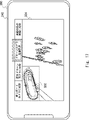
- FIG. 17 shows a video for the second user in which a superimposed image 602 indicating the position information of the designated laser is superimposed on the video 504 of the drone camera 320 in which the designated laser is captured.
- a superimposed image 602 in this figure indicates where on the track the designated racer is running. Note that the superimposed image 602 may further indicate the position of the leading laser. As a result, the user can easily grasp the situation of the entire race while confirming the state of the designated racer on the video.
- the hardware configuration is described, but it is not limited to this.
- the present disclosure can also implement arbitrary processing by causing a processor to execute a computer program.
- the program includes instructions (or software code) that, when read into a computer, cause the computer to perform one or more of the functions described in the embodiments.
- the program may be stored in a non-transitory computer-readable medium or tangible storage medium.
- computer readable media or tangible storage media may include random-access memory (RAM), read-only memory (ROM), flash memory, solid-state drives (SSD) or other memory technology, CDs - ROM, digital versatile disc (DVD), Blu-ray disc or other optical disc storage, magnetic cassette, magnetic tape, magnetic disc storage or other magnetic storage device.
- the program may be transmitted on a transitory computer-readable medium or communication medium.
- transitory computer readable media or communication media include electrical, optical, acoustic, or other forms of propagated signals.
- the image providing apparatus 100b may generate distribution data for user images using biological information from the biological information measuring device 400 attached to the body of each racer.
- the biological information measuring device 400 is attached to the body of the horse, but instead of or in addition to this, it may be attached to the body of the jockey to measure the biological information of the jockey.
- the image providing device 100b may generate the distribution data of the user image using the biometric information of each jockey.
- the racer is a boat racer
- a measuring instrument used by the racer to measure the condition of the boat may be attached to the boat.
- the image providing device 100b may acquire the state of the ship used by the designated racer and superimpose a superimposed image showing the state of the ship on the first user image, thereby generating distribution data of the user image.
- (Appendix 2) further comprising priority setting means for setting the priority of each of the plurality of cameras;
- the image providing apparatus according to appendix 1, wherein the generating means generates the user image based on the priority.
- (Appendix 3) The image according to appendix 2, wherein the priority setting means sets the priority of each of the plurality of cameras based on the degree of association between the image collected from each of the plurality of cameras and the laser ID. delivery device.
- the priority setting means sets the priority of each of the plurality of cameras based on at least one of the position information of the laser having the laser ID and the elapsed time from the start of the race. Video providing device. (Appendix 5) 5.
- the generating means selects one or more images to be displayed on the display means of the user terminal from the images collected from the plurality of cameras, based on the priority.
- video providing device (Appendix 6) 6.
- the generating means is generating a first user image from images collected from the plurality of cameras based on the user-designated laser ID; generating a superimposed image showing the state of the laser based on the position information of the laser having the laser ID specified by the user or the biological information of the laser; generating a video for a second user by superimposing the superimposed image on the video for the first user; 7.
- the video providing device according to any one of additional notes 1 to 6, wherein the output control means causes the user terminal to output the video for the second user.
- (Appendix 8) a video providing device; a user terminal used by a user, and the video providing device comprising: Designating means for acquiring a racer ID for identifying a racer designated by the user among the racers participating in the race; video collecting means for collecting videos related to the race captured in the same time interval from each of a plurality of cameras; generating means for generating a user image from images collected from the plurality of cameras based on the laser ID designated by the user; and output control means for outputting the user video to the user terminal.
- (Appendix 9) Acquiring a racer ID for identifying a racer designated by a user among the racers participating in the race; collecting images of the race taken during the same time interval from each of a plurality of cameras; generating a user image from images collected from the plurality of cameras based on the laser ID specified by the user;
- a video providing method comprising outputting the video for the user to a user terminal used by the user.
- a non-temporary computer-readable medium storing a program for causing a computer to execute an output control process for outputting the user video to a user terminal used by the user.
- Reference Signs List 10 100, 100a, 100b Image providing device 11, 141 Designating unit 12 Image collecting unit 142 Image collecting unit 15, 145, 145b Generation unit 16, 146 Output control unit 110, 110a, 110b Storage unit 111, 111a, 111b Program 112 User database 1121 User ID 1122 Racer ID 113 Racer DB 1131 Racer ID 1132 Feature information 114 Camera DB 1141 Camera ID 1142 camerawork type 1143 position information 1144 video data 115 camerawork priority rule 120 memory 130 communication unit 140, 140a, 140b control unit 143 relevance calculation unit 144 priority setting unit 144a priority setting unit 200 user terminal 220 storage unit 230 communication Section 240 Display Section 245 Audio Output Section 250 Input Section 260 Control Section 310 Fixed Camera 320 Drone Camera 330 Onboard Camera 400 Biological Information Measuring Instrument 410 Position Information Measuring Instrument 501, 502, 503, 504 Video 600, 601 Superimposed Image 1000, 1000b Video providing system N network
Abstract
映像提供装置(10)は、レースに出場するレーサのうち、ユーザが指定したレーサを識別するレーサIDを取得する指定部(11)と、複数のカメラの各々から、同じ時間区間に撮影された、レースに関する映像を収集する映像収集部(12)と、ユーザが指定したレーサIDに基づいて、複数のカメラから収集した映像からユーザ用映像を生成する生成部(15)と、ユーザ用映像を、ユーザが使用するユーザ端末に出力させる出力制御部(16)とを備える。
Description
本開示は、映像提供装置、映像提供システム、映像提供方法及び非一時的なコンピュータ可読媒体に関し、特に、レース映像を提供する映像提供装置、映像提供システム、映像提供方法及び非一時的なコンピュータ可読媒体に関する。
競馬などの競技会場では、観戦客は、大型映像ディスプレイに表示される一律の競技映像を見ることにより、競技を観戦している。そして近年、観戦客がレーサのパフォーマンスを好適に観戦するための映像配信システムが開発されている。
例えば特許文献1では、複数の選手が同時並行的に異なる位置でパフォーマンスを行うプロゴルフ競技等のライブ観戦システムが開示されている。このライブ観戦システムでは、映像収集配信設備装置が、観戦者による観視を推奨する推奨場面で所定の信号状態となる推奨フラグと、映像中に認識される選手を特定するための情報とを、放送信号に付加する。そして観戦者端末は、放送信号から推奨場面及び選手を特定するための情報を検出し、観戦者に報知する。
ここで競馬等の競技観戦においては、観戦者が所望のレーサにフォーカスした自分用のレース映像を容易に観たいというニーズがある。しかし上述の特許文献1に記載のライブ観戦システムでは、映像収集配信設備装置が、各観戦者に適した映像を直接提供することができない。このため、観戦者は、放送される映像の中から所望のレーサの映像を選択して切り替えなければならないという問題がある。
本開示の目的は、上述した課題に鑑み、ユーザが指定したレーサに関連するユーザ用のレース映像を好適に提供する映像提供装置、映像提供システム、映像提供方法及び非一時的なコンピュータ可読媒体を提供することにある。
本開示の一態様にかかる映像提供装置は、
レースに出場するレーサのうち、ユーザが指定したレーサを識別するレーサIDを取得する指定手段と、
複数のカメラの各々から、同じ時間区間に撮影された、前記レースに関する映像を収集する映像収集手段と、
前記ユーザが指定したレーサIDに基づいて、前記複数のカメラから収集した映像からユーザ用映像を生成する生成手段と、
前記ユーザ用映像を、前記ユーザが使用するユーザ端末に出力させる出力制御手段と
を備える。
レースに出場するレーサのうち、ユーザが指定したレーサを識別するレーサIDを取得する指定手段と、
複数のカメラの各々から、同じ時間区間に撮影された、前記レースに関する映像を収集する映像収集手段と、
前記ユーザが指定したレーサIDに基づいて、前記複数のカメラから収集した映像からユーザ用映像を生成する生成手段と、
前記ユーザ用映像を、前記ユーザが使用するユーザ端末に出力させる出力制御手段と
を備える。
本開示の一態様にかかる映像提供システムは、
映像提供装置と、
ユーザが使用するユーザ端末と
を備え
前記映像提供装置は、
レースに出場するレーサのうち、前記ユーザが指定したレーサを識別するレーサIDを取得する指定手段と、
複数のカメラの各々から、同じ時間区間に撮影された、前記レースに関する映像を収集する映像収集手段と、
前記ユーザが指定したレーサIDに基づいて、前記複数のカメラから収集した映像からユーザ用映像を生成する生成手段と、
前記ユーザ用映像を、前記ユーザ端末に出力させる出力制御手段と
を有する。
映像提供装置と、
ユーザが使用するユーザ端末と
を備え
前記映像提供装置は、
レースに出場するレーサのうち、前記ユーザが指定したレーサを識別するレーサIDを取得する指定手段と、
複数のカメラの各々から、同じ時間区間に撮影された、前記レースに関する映像を収集する映像収集手段と、
前記ユーザが指定したレーサIDに基づいて、前記複数のカメラから収集した映像からユーザ用映像を生成する生成手段と、
前記ユーザ用映像を、前記ユーザ端末に出力させる出力制御手段と
を有する。
本開示の一態様にかかる映像提供方法は、
レースに出場するレーサのうち、ユーザが指定したレーサを識別するレーサIDを取得し、
複数のカメラの各々から、同じ時間区間に撮影された、前記レースに関する映像を収集し、
前記ユーザが指定したレーサIDに基づいて、前記複数のカメラから収集した映像からユーザ用映像を生成し、
前記ユーザ用映像を、前記ユーザが使用するユーザ端末に出力させる。
レースに出場するレーサのうち、ユーザが指定したレーサを識別するレーサIDを取得し、
複数のカメラの各々から、同じ時間区間に撮影された、前記レースに関する映像を収集し、
前記ユーザが指定したレーサIDに基づいて、前記複数のカメラから収集した映像からユーザ用映像を生成し、
前記ユーザ用映像を、前記ユーザが使用するユーザ端末に出力させる。
本開示の一態様にかかる非一時的なコンピュータ可読媒体は、
レースに出場するレーサのうち、ユーザが指定したレーサを識別するレーサIDを取得する指定処理と、
複数のカメラの各々から、同じ時間区間に撮影された、前記レースに関する映像を収集する映像収集処理と、
前記ユーザが指定したレーサIDに基づいて、前記複数のカメラから収集した映像からユーザ用映像を生成する生成処理と、
前記ユーザ用映像を、前記ユーザが使用するユーザ端末に出力させる出力制御処理と
をコンピュータに実行させるためのプログラムが格納される。
レースに出場するレーサのうち、ユーザが指定したレーサを識別するレーサIDを取得する指定処理と、
複数のカメラの各々から、同じ時間区間に撮影された、前記レースに関する映像を収集する映像収集処理と、
前記ユーザが指定したレーサIDに基づいて、前記複数のカメラから収集した映像からユーザ用映像を生成する生成処理と、
前記ユーザ用映像を、前記ユーザが使用するユーザ端末に出力させる出力制御処理と
をコンピュータに実行させるためのプログラムが格納される。
本開示により、ユーザが指定したレーサに関連するユーザ用のレース映像を好適に提供する映像提供装置、映像提供システム、映像提供方法及び非一時的なコンピュータ可読媒体を提供できる。
以下では、本開示の実施形態について、図面を参照しながら詳細に説明する。各図面において、同一又は対応する要素には同一の符号が付されており、説明の明確化のため、必要に応じて重複説明は省略される。
<実施形態1>
まず、本開示の実施形態1について説明する。図1は、実施形態1にかかる映像提供装置10の構成を示すブロック図である。映像提供装置10は、レース競技の映像を観戦者であるユーザに提供するコンピュータ装置である。レース競技は、トラック上を複数のレーサが速さを競い合う競技であってよい。例えば、レース競技は、競馬、競艇、競輪、カーレース、陸上トラック競技、又はスピードスケート等であってよい。レーサは、競争を行う競技者、動物(例えば競走馬)、又は競争に使用する用具(例えば自動車若しくは自転車)であってよい。
まず、本開示の実施形態1について説明する。図1は、実施形態1にかかる映像提供装置10の構成を示すブロック図である。映像提供装置10は、レース競技の映像を観戦者であるユーザに提供するコンピュータ装置である。レース競技は、トラック上を複数のレーサが速さを競い合う競技であってよい。例えば、レース競技は、競馬、競艇、競輪、カーレース、陸上トラック競技、又はスピードスケート等であってよい。レーサは、競争を行う競技者、動物(例えば競走馬)、又は競争に使用する用具(例えば自動車若しくは自転車)であってよい。
ここで、映像提供装置10は、ネットワーク(不図示)に接続される。ネットワークは、有線であっても無線であってもよい。また、当該ネットワークには、ユーザが使用するユーザ端末(不図示)が接続されている。つまり、映像提供装置10は、ネットワークを介してユーザ端末と通信可能に接続される。
映像提供装置10は、指定部11と、映像収集部12と、生成部15と、出力制御部16とを備える。
指定部11は、指定手段とも呼ばれる。指定部11は、レースに出場するレーサのうち、ユーザが指定したレーサを識別するレーサIDを取得する。以下では、ユーザが指定したレーサを、指定レーサと呼ぶことがある。
映像収集部12は、映像収集手段とも呼ばれる。映像収集部12は、複数のカメラの各々から、同じ時間区間に撮影された、レースに関する映像を収集する。複数のカメラは、異なるカメラワークを有するカメラを含んでよい。カメラワークとは、画角、カメラの移動の有無、又は移動態様等であってよい。時間区間とは、同じタイミング又は同じ時間帯に撮影された映像であるとユーザが認識できる程度の時間間隔であり、例えば1~数フレームレート[fps]、又は数~数十[s]といった時間間隔であってよい。時間間隔は、複数のカメラのフレームレートに基づいて予め定められてよい。
生成部15は、生成手段とも呼ばれる。生成部15は、指定レーサのレーサIDに基づいて、上述した複数のカメラから収集した映像から、ユーザ用映像を生成する。
出力制御部16は、出力制御手段とも呼ばれる。出力制御部16は、ユーザ用映像をユーザ端末に出力させる。例えば、出力制御部16は、ユーザ用映像のストリーミングデータをユーザ端末に送信(配信)し、ユーザ端末は、リアルタイムで表示部(不図示)にユーザ用映像を表示する。あるいは出力制御部16は、ユーザ用映像のストックデータをまとめてユーザ端末に送信し、ユーザ端末は表示部(不図示)にそのユーザ用映像を表示してもよい。以下では、このようなストリーミングデータ又はストックデータを、配信データと呼ぶことがある。
図2は、実施形態1にかかる映像提供方法の流れを示すフローチャートである。まず映像提供装置10の指定部11は、ユーザが指定したレーサのレーサIDを取得する(S10)。次に、映像収集部12は、複数のカメラの各々から、同じ時間区間に撮影された映像を収集する(S11)。次に、生成部15は、指定部11が取得したレーサIDに基づいて、映像収集部12が収集した映像からユーザ用映像を生成する(S12)。次に、出力制御部16は、ユーザ用映像をユーザ端末に出力させる(S13)。
このように実施形態1によれば、映像提供装置10は、ユーザが指定したレーサに関連するユーザ用のレース映像を好適に提供することができる。これにより、ユーザは所望のレース映像を好適に観ることができるため、ユーザの満足度が向上する。
<実施形態2>
次に、本開示の実施形態2について説明する。図3は、実施形態2にかかる映像提供システム1000の全体構成を示すブロック図である。映像提供システム1000は、レース競技の映像を観戦者であるユーザに提供するコンピュータシステムである。映像提供システム1000は、1又は複数の固定カメラ310と、1又は複数のドローンカメラ320と、1又は複数のオンボードカメラ330と、映像提供装置100と、ユーザ端末200とを備える。固定カメラ310、ドローンカメラ320及びオンボードカメラ330と、映像提供装置100とは、無線で接続されている。本実施形態2では、固定カメラ310、ドローンカメラ320及びオンボードカメラ330と映像提供装置100とは、5G(5th Generation Mobile Communication System)又はローカル5Gのネットワークで接続されている。しかしこれに代えて、各種カメラと映像提供装置100とは、他の移動体通信システムのネットワーク、又はWi-Fi(登録商標)といった無線LAN(Local Area Network)で接続されていてもよい。あるいは、各種カメラのうち、有線で映像提供装置100と接続されているカメラがあってもよい。そして映像提供装置100とユーザ端末200とは、ネットワークNを介して互いに接続されている。ここで、ネットワークNは、有線又は無線の通信回線である。
次に、本開示の実施形態2について説明する。図3は、実施形態2にかかる映像提供システム1000の全体構成を示すブロック図である。映像提供システム1000は、レース競技の映像を観戦者であるユーザに提供するコンピュータシステムである。映像提供システム1000は、1又は複数の固定カメラ310と、1又は複数のドローンカメラ320と、1又は複数のオンボードカメラ330と、映像提供装置100と、ユーザ端末200とを備える。固定カメラ310、ドローンカメラ320及びオンボードカメラ330と、映像提供装置100とは、無線で接続されている。本実施形態2では、固定カメラ310、ドローンカメラ320及びオンボードカメラ330と映像提供装置100とは、5G(5th Generation Mobile Communication System)又はローカル5Gのネットワークで接続されている。しかしこれに代えて、各種カメラと映像提供装置100とは、他の移動体通信システムのネットワーク、又はWi-Fi(登録商標)といった無線LAN(Local Area Network)で接続されていてもよい。あるいは、各種カメラのうち、有線で映像提供装置100と接続されているカメラがあってもよい。そして映像提供装置100とユーザ端末200とは、ネットワークNを介して互いに接続されている。ここで、ネットワークNは、有線又は無線の通信回線である。
固定カメラ310は、レース会場の異なる場所に設置されている。例えば各固定カメラ310は、トラックのスタート地点、中盤地点及びゴール地点のそれぞれの風景を撮影できるような場所に設置されていてよい。
ドローンカメラ320は、レース風景を空中で撮影するカメラである。ドローンカメラ320は、1又は複数のレーサに追従するように移動し、1又は複数のレーサを空中で撮影してよい。
オンボードカメラ330は、各レーサの身体、又は各レーサが使用する用具に取り付けられ、各レーサの移動に伴って移動するカメラである。例えばオンボードカメラ330は、各レーサの視野を撮影するカメラである。
映像提供装置100は、上述した映像提供装置10の一例である。映像提供装置100は、互いにカメラワークの異なる固定カメラ310、ドローンカメラ320、及びオンボードカメラ330の各々から、映像を収集する。そして映像提供装置100は、収集した映像に基づいて、ユーザが指定したレーサに関連するユーザ用映像を生成する。そして映像提供装置100は、生成したユーザ用映像を、ネットワークNを介してユーザ端末に送信する。
ユーザ端末200は、ユーザが使用する情報端末である。ユーザ端末200は、映像提供装置100に対して、指定レーサのレーサIDを通知する。例えばユーザ端末200は、レースに関するウェブページ又はアプリにアクセスし、レーサの一覧を表示させてユーザにユーザIDの選択を促す。そしてユーザ端末200は、選択されたユーザIDを映像提供装置100に通知する。また例えばユーザ端末200は、ユーザが購入した投票券(例えば、馬券)に紐づけられたレーサのIDを、映像提供装置100に通知する。一例としてユーザ端末200は、購入したレースの投票券に記載されたQRコード(登録商標)を読み取ることにより、映像提供装置100に指定レーサのレーサIDを通知してよい。尚、レーサIDの通知は、ユーザ端末200に代えて、投票券の販売を管理する外部装置が行ってもよい。そしてユーザ端末200は、レースの開催時間に映像提供装置100からユーザ用映像の配信データを受信し、配信データに従ってユーザ用映像を表示する。
図4は、実施形態2にかかるユーザ端末200の構成を示すブロック図である。ユーザ端末200は、記憶部220と、通信部230と、表示部240と、音声出力部245と、入力部250と、制御部260とを備える。
記憶部220は、ユーザ端末200の各機能を実現するためのプログラムが格納される記憶装置である。通信部230は、ネットワークNとの通信インタフェースである。表示部240は、表示装置である。音声出力部245は、音声を出力するスピーカを含む。入力部250は、入力を受け付ける入力装置である。表示部240及び入力部250は、タッチパネルのように、一体的に構成されていてもよい。制御部260は、ユーザ端末200が有するハードウェアの制御を行う。
例えば、制御部260は、通信部230を介して映像提供装置100から、レーサIDを指定するための入力画面を受信したことに応じて、受信した入力画面を表示部240に表示する。そして、制御部260は、入力部250を介してレーサIDの入力を受け付けた場合、通信部230を介して、レーサIDを映像提供装置100に送信する。あるいは、制御部260は、購入した投票券に記載されたQRコードを読み取ることで取得したレーサIDを、映像提供装置100に送信する。そして制御部260は、通信部230を介して映像提供装置100から、ユーザ用映像を含む配信データを受信したことに応じて、受信した配信データに基づいて、ユーザ用映像を表示部240に表示する。
図5は、実施形態2にかかる映像提供装置100の構成を示すブロック図である。映像提供装置100は、記憶部110、メモリ120、通信部130、及び制御部140を備える。
記憶部110は、ハードディスク、フラッシュメモリ等の記憶装置である。記憶部110は、プログラム111と、ユーザDB112と、レーサDB113と、カメラDB114とを記憶する。プログラム111は、本実施形態2にかかる映像提供方法の処理が実装されたコンピュータプログラムである。
ユーザDB112は、ユーザID1121と、レーサID1122とを対応付けるデータベースである。ここで、ユーザID1121は、ユーザを識別する情報である。そしてレーサID1122は、ユーザが指定した指定レーサを識別する情報である。
レーサDB113は、レーサID1131と、特徴情報1132とを対応付けるデータベースである。レーサID1131は、レースに出場する各レーサを識別する情報である。特徴情報1132は、レーサID1131を有するレーサを撮影した画像から抽出される特徴量を示す情報である。例えばレーサが選手である場合、特徴情報1132は顔の特徴量を示す情報であってよい。特徴情報1132は、これに代えて、レーサが装着する服装(例えばユニフォーム若しくはゼッケン)、又はレーサが使用する用具(例えば自動車若しくは自転車)を撮影した画像から抽出される特徴量を示す情報であってもよい。例えばレーサがゼッケンを装着している場合、特徴情報1132は、ゼッケンの数字の特徴量を示す情報であってよい。
カメラDB114は、カメラID1141と、カメラワーク種別1142と、位置情報1143と、映像データ1144とを対応付けるデータベースである。
カメラID1141は、固定カメラ310、ドローンカメラ320、及びオンボードカメラ330に含まれる各カメラを識別する情報である。カメラワーク種別1142は、そのカメラのカメラワークの種別を示す情報である。上述の通り、カメラワークとは、画角、移動の有無、又は移動態様等であってよく、カメラワーク種別1142は、固定カメラ310、ドローンカメラ320、及びオンボードカメラ330の別を示す情報であってよい。位置情報1143は、そのカメラの位置情報である。例えばカメラが固定カメラ310である場合、位置情報1143はそのカメラの設置場所の位置情報であってよい。またカメラがドローンカメラ320やオンボードカメラ330である場合、位置情報1143は、そのカメラが受信したGPS(Global Positioning System)情報であってよい。映像データ1144は、そのカメラが撮影し、映像提供装置100がそのカメラから取得した映像データである。
カメラID1141は、固定カメラ310、ドローンカメラ320、及びオンボードカメラ330に含まれる各カメラを識別する情報である。カメラワーク種別1142は、そのカメラのカメラワークの種別を示す情報である。上述の通り、カメラワークとは、画角、移動の有無、又は移動態様等であってよく、カメラワーク種別1142は、固定カメラ310、ドローンカメラ320、及びオンボードカメラ330の別を示す情報であってよい。位置情報1143は、そのカメラの位置情報である。例えばカメラが固定カメラ310である場合、位置情報1143はそのカメラの設置場所の位置情報であってよい。またカメラがドローンカメラ320やオンボードカメラ330である場合、位置情報1143は、そのカメラが受信したGPS(Global Positioning System)情報であってよい。映像データ1144は、そのカメラが撮影し、映像提供装置100がそのカメラから取得した映像データである。
メモリ120は、RAM(Random Access Memory)等の揮発性記憶装置であり、制御部140の動作時に一時的に情報を保持するための記憶領域である。通信部130は、ネットワークNとの通信インタフェースと、各カメラとの通信インタフェースとを含む。
制御部140は、映像提供装置100の各構成を制御するプロセッサつまり制御装置である。制御部140は、記憶部110からプログラム111をメモリ120へ読み込ませ、プログラム111を実行する。これにより、制御部140は、指定部141、映像収集部142、関連度算出部143、優先度設定部144、生成部145及び出力制御部146の機能を実現する。
指定部141は、上述した指定部11の一例である。指定部141は、ユーザ端末200からネットワークNを介してデータを受信する。ここで、受信したデータには、指定レーサのレーサIDに加えて、ユーザ端末200のユーザのユーザIDが含まれてよい。そして指定部141は、ユーザDB112に、ユーザIDに対応付けてレーサIDを登録する。指定部141は、レースの開催時間になった場合、ユーザIDに対応付けられたレースIDを、ユーザDB112から取得し、関連度算出部143に供給する。
映像収集部142は、上述した映像収集部12の一例である。映像収集部142は、所定のフレームレートで、固定カメラ310、ドローンカメラ320及びオンボードカメラ330を含む複数のカメラの各々から、映像データを受信し、同じ時間区間に撮影された複数の映像データを収集する。
関連度算出部143は、関連度算出手段とも呼ばれる。関連度算出部143は、複数のカメラの各々から収集した映像データと、レーサIDとの間の関連度を算出する。関連度は、その映像データに指定レーサが映っているか否かに基づいて、算出されてよい。例えば、まず関連度算出部143は、各映像データについて、レーサDB113において指定レーサのレーサIDに対応付けられた特徴情報1132を用いて、関連度を算出する。具体的には、関連度算出部143は、各映像データについて、その映像データのフレーム画像から特徴情報を抽出し、抽出した特徴情報と特徴情報1132とを比較することで関連度を算出する。また関連度は、その映像データに指定レーサが映っているか否かに加えて、指定レーサの画像領域の大きさ、フレーム画像におけるその画像領域の位置及びピントがどの程度合っているか等に基づいて算出されてもよい。
ここで、関連度算出部143は、カメラワーク種別ごとに、そのカメラワーク種別を有するカメラの各々から収集した映像データと、レーサIDとの間の関連度を算出してよい。例えば関連度算出部143は、複数の固定カメラ310から収集した映像データの各々について、レーサIDとの間の関連度を算出し、複数のオンボードカメラ330から収集した映像データの各々について、レーサIDとの間の関連度を算出してよい。
尚、オンボードカメラ330の場合、撮影した映像は取り付け先のレーサと関連性が強いものの、映像中に取り付け先のレーサが映らない。このため、上述の方法では、関連度が正しく算出されない可能性がある。したがって、上述した方法により関連度を算出するのは、オンボードカメラ330を除くカメラの映像データについてのみであってよい。そして関連度算出部143は、オンボードカメラ330の映像については、そのオンボードカメラ330が指定レーサに取り付けられているか否かに基づいて関連度を算出してよい。
また、関連度算出部143は、映像を撮影したタイミングのレーサの位置情報が把握できる場合には、レーサの位置情報と、映像の撮影元のカメラの位置情報とに基づいて、関連度を算出してもよい。具体的には、まず関連度算出部143は、収集した各映像データについて、その映像を撮影したカメラのカメラIDに対応する位置情報1143をカメラDB114から特定する。そして関連度算出部143は、指定レーサの近くに位置するカメラほど、関連度が高くなるように関連度を算出してよい。尚、関連度算出部143は、レーサの位置情報を、オンボードカメラ330の位置情報から推定してよい。この場合も、この方法により関連度を算出するのは、オンボードカメラ330を除くカメラの映像データについてのみであってよい。
優先度設定部144は、優先度設定手段とも呼ばれる。優先度設定部144は、固定カメラ310、ドローンカメラ320及びオンボードカメラ330を含む、複数のカメラの各々の優先度を設定する。本実施形態2では、優先度設定部144は、関連度算出部143が算出した、各映像データについての関連度に基づいて、各カメラの優先度を設定する。例えば優先度設定部144は、レーサIDとの間の関連度が高い映像データを撮影したカメラほど、優先度を高く設定する。これにより、指定レーサと関連性が強い映像、例えばそのレーサがメインとして映っている映像の優先度を高めて、ユーザ端末200に表示することができる。
生成部145は、上述した生成部15の一例である。生成部145は、優先度設定部144が設定した優先度に基づいてユーザ用映像の配信データを生成する。例えば生成部145は、優先度に基づいて、複数のカメラから収集した映像データから、ユーザ端末200の表示手段において表示させる1又は複数の映像データを選択する。このとき生成部145は、カメラワーク種別ごとに、優先度に基づいて、そのカメラワーク種別を有するカメラの各々から収集した映像データから映像データを選択してよい。一例として、生成部145は、複数の固定カメラ310の映像データから1の映像データを、複数のドローンカメラ320の映像データから1の映像データを、複数のオンボードカメラ330の映像データから1の映像データを選択してよい。そして生成部145は、選択した映像データが複数ある場合、優先度に基づいて、ユーザ端末200の表示部240において選択した映像データの表示態様を決定してよい。表示態様とは、表示位置若しくは表示サイズであってもよいし、その映像データを表示部240上でアクティブにさせるか否かであってもよい。例えば生成部145は、選択した映像データのうち、優先度が高い映像データほど表示部240の画面中心に表示されるように、又は表示サイズが大きくなるように、表示態様を決定してよい。また例えば生成部145は、選択した映像データのうち、優先度が最も高い映像データを、表示部240上でアクティブに表示される映像データとして決定してよい。
そして生成部145は、選択した映像データと、表示態様に関する情報とを含むユーザ用映像の配信データを、出力制御部146に供給する。
出力制御部146は、上述した出力制御部16の一例である。出力制御部146は、ユーザ用映像の配信データを、ユーザ端末200に送信し、ユーザ端末200の表示部240にユーザ用映像を表示させる。
図6は、実施形態2にかかる映像提供方法の流れを示すフローチャートである。まず映像提供装置100の指定部141は、レースの開催時間になったことに応じて、ユーザが指定したレーサのレーサIDであって、ユーザIDに対応付けられたレーサIDを、ユーザDB112から取得する(S20)。指定部141は、レーサIDを関連度算出部143に供給する。次に、映像収集部142は、複数のカメラの各々から、同じ時間区間に撮影された映像データの収集を開始する(S21)。次に、関連度算出部143は、各映像データについて、レーサID及びその映像データに基づいて、その映像データと指定レーサとの間の関連度を算出する(S22)。次に、優先度設定部144は、各映像データの関連度に基づいて、その映像データを撮影したカメラの優先度を設定する(S23)。次に、生成部145は、各カメラの優先度に基づいて、ユーザ用映像の配信データを生成する(S24)。例えば生成部145は、各カメラの優先度に基づいて選択された映像データと、各カメラの優先度に基づいて決定した表示態様に関する情報とを、ユーザ用映像の配信データとして生成する。そして出力制御部146は、配信データを、ネットワークNを介してユーザ端末200に送信し、ユーザ端末200にユーザ用映像を表示させる(S25)。
図7は、実施形態2にかかるユーザ端末200に表示される表示画面の一例を示す図である。一例としてユーザは、レーサID「2」のレーサ(競走馬)を指定したとする。図7に示すように、配信データに含まれるユーザ用映像には、レーサID「2」のレーサが映った固定カメラ310の映像501と、レーサID「2」のレーサに取り付けられたオンボードカメラ330の映像502とが含まれている。そしてユーザ端末200は、配信データに含まれる表示態様に関する情報に基づいて、映像501及び映像502を、2画面構成になるように表示部240に表示している。尚、表示部240には、上述したユーザ用映像に加えて、指定レーサに関する情報を表示してもよい。指定レーサに関する情報は、指定レーサの氏名、レーサ番号(馬番や枠番)、年齢、性別、戦績、並びに、指定レーサが馬である場合は騎手の名前を含んでよい。
図8及び図9は、実施形態2にかかるユーザ端末200に表示される表示画面の他の例を示す図である。例えば配信データには、上述した固定カメラ310の映像501と、レーサID「2」のレーサが映ったドローンカメラ320の映像504(不図示)と、上述したオンボードカメラ330の映像502とが含まれる。ユーザ端末200は、配信データに含まれる映像のうち1の映像のみを表示部240にアクティブに表示し、残りの映像については非アクティブに表示する(つまり、隠す)。図8では、ドローンカメラ320の映像502がアクティブに表示され、残りの映像は非アクティブに表示されている。ユーザは、表示部240に表示された、カメラワーク種別を示すタブをタップにより選択することで、アクティブな映像を切り替えることができるようになっている。例えば、ユーザは、指定レーサが位置する集団の俯瞰映像を観たい場合、「ドローンカメラに切替」というタブを選択する。ユーザ端末200は、タブ選択が切り替わったことに応じて、切替前にアクティブ表示されていた映像を非アクティブに変更し、切替後のタブに対応するカメラの映像をアクティブ表示に切り替えてよい。
さらに、配信データには、優先度が低い(例えば指定レーサとの関連性が低い)カメラの映像データも含まれてよい。本例では、配信データには、先頭の競走馬の映像503(不図示)が含まれる。例えば映像503は、いずれかの固定カメラ310の映像であってよい。例えばユーザが、「先頭の馬の映像に切替」というタブを選択することで、図8に示す表示画面が図9に示す表示画面に移行する。図9では、先頭の競走馬が映る固定カメラ310の映像503がアクティブに表示されている。
また、優先度が低いカメラの他の例としては、レース会場全体を俯瞰するカメラが挙げられる。そしてユーザ端末200の表示画面には、上記カメラの映像に切り替えるタブがあってもよい。ユーザが上記タブを選択することにより、上記カメラの映像をアクティブ表示に切り替えることができる。
このように実施形態2によれば、映像提供装置100は、指定したレーサと関連度の高いカメラ映像が優先的に表示されるように構成されるユーザ用映像を、ユーザに提供することができる。これにより、ユーザは所望のレーサのレース映像を好適に観ることができるため、ユーザの満足度が向上する。
<実施形態3>
次に、本開示の実施形態3について説明する。現状のレース映像においては、レースの序盤、中盤及び終盤等の段階に応じて、放送するカメラ映像を手動で選択して、編集している。また、レーサのパフォーマンスに応じて、放送するカメラ映像を手動で選択して、編集している。実施形態3は、映像提供装置がこのようなレースの状況に応じて各カメラの優先度を変化させ、これによりユーザ用映像を自動編集することに特徴を有する。
次に、本開示の実施形態3について説明する。現状のレース映像においては、レースの序盤、中盤及び終盤等の段階に応じて、放送するカメラ映像を手動で選択して、編集している。また、レーサのパフォーマンスに応じて、放送するカメラ映像を手動で選択して、編集している。実施形態3は、映像提供装置がこのようなレースの状況に応じて各カメラの優先度を変化させ、これによりユーザ用映像を自動編集することに特徴を有する。
図10は、実施形態3にかかる映像提供装置100aの構成を示すブロック図である。映像提供装置100aは、映像提供装置100と基本的に同様の構成及び機能を有するが、記憶部110及び制御部140に代えて、記憶部110a及び制御部140aを備える点で相違する。
記憶部110aは、プログラム111に代えてプログラム111aを記憶する。プログラム111aは、実施形態3にかかる映像提供方法の処理が実装されたコンピュータプログラムである。
また記憶部110aは、カメラワーク優先ルール115を記憶する。カメラワーク優先ルール115は、レースの状況に応じて優先度を変化させるためのルールである。本実施形態4では、カメラワーク優先ルール115は、各カメラワーク種別について、そのカメラワークを有するカメラの優先度を示すカメラワーク優先度を定めるためのルールである。レースの状況とは、各レーサの位置情報、レーサ同士の位置関係及びレースの開始からの経過時間のうち少なくとも1つであってよい。
また記憶部110aは、カメラワーク優先ルール115を記憶する。カメラワーク優先ルール115は、レースの状況に応じて優先度を変化させるためのルールである。本実施形態4では、カメラワーク優先ルール115は、各カメラワーク種別について、そのカメラワークを有するカメラの優先度を示すカメラワーク優先度を定めるためのルールである。レースの状況とは、各レーサの位置情報、レーサ同士の位置関係及びレースの開始からの経過時間のうち少なくとも1つであってよい。
制御部140aは、優先度設定部144に代えて優先度設定部144aを有する点で制御部140と相違する。
優先度設定部144aは、関連度及びカメラワーク優先ルール115に基づいて、各カメラの優先度を設定する。例えばまず優先度設定部144aは、カメラワーク優先ルール115に基づいて各カメラワーク種別について、カメラワーク優先度を設定する。つまり優先度設定部144aは、指定レーサの位置情報、指定レーサと他レーサとの位置関係及びレースの開始からの経過時間の少なくとも1つに基づいて、各カメラワーク種別についてカメラワーク優先度を設定する。また優先度設定部144aは、上述の実施形態2と同様に、複数のカメラから収集した映像データの関連度に基づいて、そのカメラの個別優先度を設定する。個別優先度の設定方法は、実施形態2にかかる優先度の設定方法と同様であってよい。そして優先度設定部144aは、カメラワーク優先度及び個別優先度に基づいて、各カメラの優先度を設定する。
そして生成部145は、優先度設定部144aが設定した優先度に基づいてユーザ用映像の配信データを生成する。
図11は、実施形態3にかかるカメラワーク優先ルール115の一例を説明するための図である。本図のカメラワーク優先ルール115は、レースの開始からの経過時間に応じた、優先対象となるカメラワーク種別を定めている。例えば、優先度設定部144aは、レースの開始からt1~t2では、カメラワーク種別が固定カメラであるカメラのカメラワーク優先度を所定量加算する。また例えば、優先度設定部144aは、レースの開始からt2~t3では、カメラワーク種別がドローンカメラであるカメラのカメラワーク優先度を所定量加算する。また例えば、優先度設定部144aは、レースの開始からt3~t4では、カメラワーク種別がオンボードカメラであるカメラのカメラワーク優先度を所定量加算する。また例えば、優先度設定部144aは、レースの開始からt4以降では、カメラワーク種別が固定カメラであるカメラのカメラワーク優先度を所定量加算する。
尚、カメラワーク優先ルール115に加えて又は代えて、優先度設定部144aは、何らかのイベントを検出した場合に、その場面を撮影しているカメラの優先度を所定量高めると定めたルールを採用してもよい。何らかのイベントとは、例えばレーサ同士が競っており、互いに近い距離にいる場合や衝突した場合、あるいは、レーサが馬であれば騎手が落馬した場合であってよい。具体的には、優先度設定部144aは、レーサ同士の距離が所定閾値以内である場合や、いずれかのレーサから衝撃を検出した場合に、そのレーサのオンボードカメラの優先度やそのレーサを映しているカメラの優先度を所定量加算してよい。また、優先度設定部144aは、所定の地点(例えばゴール地点)付近に到達したレーサがいる場合、ゴール地点付近に設置された固定カメラの優先度を所定量加算すると定めたルールを採用してもよい。具体的には、優先度設定部144aは、各レーサの位置情報に基づいて、いずれかのレーサが所定の地点から所定距離以内に到達したと判定した場合、ゴール地点付近に設置された固定カメラの優先度を所定量加算してよい。上述のようなイベントを検出した場合には、その場面を撮影しているカメラの優先度を他のカメラよりも高くなるように設定してよい。これにより、その場面の映像をユーザ端末200上で確実に割り込み表示させることができる。
図12は、実施形態3にかかるユーザ端末200に表示される表示画面の一例を示す図である。図12は、レースの開始からt1~t2におけるユーザ用映像を示している。本例の配信データに含まれるユーザ用映像には、指定レーサが映っている固定カメラ310の映像501と、指定レーサが映っているドローンカメラ320の映像504と、指定レーサに取り付けられたオンボードカメラ330の映像502とが含まれる。レースの開始からt1~t2においては、固定カメラが優先されるため、映像501の表示サイズが大きくなっている。そして固定カメラに比べて優先度の低いドローンカメラ320の映像504及びオンボードカメラ330の映像502は、映像501よりも小さく表示されている。
このように実施形態3によれば、映像提供装置100aは、レースの状況に応じて定められるカメラワーク優先ルール115に沿って、ユーザ用映像を自動で編集することができる。例えば映像提供装置100aは、レース初期は引きの固定カメラを、レース中盤はドローンカメラやオンボードカメラを、レース終盤はゴール付近の寄りの固定カメラを優先表示させるといった編集が可能となり、ユーザの満足度をさらに高めることができる。
尚、優先度設定部144aは、レースの状況に合わせてカメラワーク優先度を出力する学習済のカメラワーク優先度設定モデルを用いて、各カメラのカメラワーク優先度を設定してもよい。例えばカメラワーク優先度設定モデルは、放送された映像のカメラワーク種別とその放送タイミングとを入力とし、各カメラワーク種別の、所定のタイミングでのカメラワーク優先度を出力するモデルであってよい。学習を重ねることで、より自然なカメラワークの自動切替を実現することができる。
<実施形態4>
次に、本開示の実施形態4について説明する。実施形態4は、映像提供装置が指定レーサの位置情報又はバイタル(生体情報)に基づいて、映像に指定レーサの状態を表現した演出を施すことに特徴を有する。
次に、本開示の実施形態4について説明する。実施形態4は、映像提供装置が指定レーサの位置情報又はバイタル(生体情報)に基づいて、映像に指定レーサの状態を表現した演出を施すことに特徴を有する。
図13は、実施形態4にかかる映像提供システム1000bの全体構成を示すブロック図である。映像提供システム1000bは、映像提供装置100aに代えて、映像提供装置100bと、1又は複数の生体情報計測器400と、1又は複数の位置情報計測器410とを備える。
生体情報計測器400は、各レーサの身体に装着され、各レーサの生体情報を計測する計測器である。生体情報は、例えば心拍、脈拍及び血圧等である。生体情報計測器400は、計測した生体情報を、レーサIDとともに映像提供装置100bに送信する。
位置情報計測器410は、各レーサの身体、又は各レーサが使用する用具に取り付けられ、各レーサの位置情報を計測する計測器である。位置情報計測器410は、オンボードカメラ330に実装されていてもよい。位置情報計測器410は、GPS情報を受信することで、位置情報を計測してよい。位置情報計測器410は、計測した位置情報を、レーサIDとともに映像提供装置100bに送信する。
映像提供装置100bは、各レーサの生体情報及び各レーサの位置情報のうち少なくとも1つを用いて、ユーザ用映像の配信データを生成する。そして映像提供装置100bは、配信データをユーザ端末200に送信する。
図14は、実施形態4にかかる映像提供装置100bの構成を示すブロック図である。映像提供装置100bは、記憶部110a及び制御部140aに代えて、記憶部110b及び制御部140bを備える点で、映像提供装置100aと相違する。
記憶部110bは、プログラム111aに代えてプログラム111bを記憶する。プログラム111bは、実施形態4にかかる映像提供方法の処理が実装されたコンピュータプログラムである。
制御部140bは、生成部145に代えて生成部145bを備える点で制御部140aと相違する。まず生成部145bは、優先度設定部144aが設定した優先度に基づいて、複数のカメラから収集した映像から第1ユーザ用映像を生成する。優先度は、指定レーサのレーサIDに基づいて算出された関連度に基づいて設定される。尚、本実施形態4では、優先度は、上述の実施形態3と同様に、関連度に加えてカメラワーク優先ルール115に基づいて設定される。尚、第1ユーザ用映像の生成方法については、実施形態2にかかるユーザ用映像の生成方法と同様であってよい。
次に生成部145bは、指定レーサの状態を示す重畳画像を生成する。指定レーサの状態は、指定レーサの位置情報又は生体情報であってよい。言い換えると生成部145bは、指定レーサの位置情報に基づいて、位置情報を示す重畳画像を生成したり、指定レーサの生体情報に基づいて、生体情報を示す重畳画像を生成する。そして生成部145bは、生成した重畳画像を第1ユーザ用映像に重畳させた第2ユーザ用映像を生成する。尚、生成部145bは、第1ユーザ用映像に含まれる映像を撮影したカメラのカメラワーク種別に応じて、重畳画像を重畳させるか否か、及び重畳画像の重畳位置を決めてよい。また生成部145bは、当該カメラワーク種別に応じて、重畳させる重畳画像の種別(生体情報を示す重畳画像か、位置情報を示す重畳画像か)を決めてもよい。生成部145bは、第2ユーザ用映像と、表示態様に関する情報とを含むユーザ用映像の配信データを生成し、出力制御部146に供給する。
出力制御部146は、上述した第2ユーザ用映像を含む配信データをユーザ端末200に送信し、ユーザ端末200の表示部240に第2ユーザ用映像を表示させる。
図15は、実施形態4にかかる映像提供方法の流れを示すフローチャートである。図15に示すステップは、図6に示すS20~S22に加えて、S30~S36を含む。
関連度算出部143が各映像データについて指定レーサとの間の関連度を算出した後(S22)、優先度設定部144aは、関連度及びカメラワーク優先ルール115に基づいて、各カメラの優先度を設定する(S30)。次に、生成部145bは、各カメラの優先度に基づいて、第1ユーザ用映像を生成する(S31)。次に、生成部145bは、指定レーサの生体情報又は位置情報を、生体情報計測器400又は位置情報計測器410から取得する(S33)。次に、生成部145bは、指定レーサの生体情報又は位置情報に基づいて、レーサの状態を示す重畳画像を生成する(S34)。次に、生成部145bは、第1ユーザ用映像に重畳画像を重畳させた第2ユーザ用映像の配信データを生成する(S35)。そして出力制御部146は、配信データをユーザ端末200に送信し、ユーザ端末200に第2ユーザ用映像を表示させる(S36)。
図16~図17は、実施形態4にかかるユーザ端末200に表示される表示画面の一例を示す図である。図16は、指定レーサに取り付けられたオンボードカメラ330の映像502に対して、指定レーサの生体情報を示す重畳画像600を重畳させた第2ユーザ用映像を示している。本図の重畳画像600は、指定レーサの心拍数がどの程度高まっているかを示している。これにより、ユーザは指定レーサの現在の状態を容易に把握してレースの臨場感をより感じることができる。尚、本図では、第2ユーザ用映像には、指定レーサの速度を示す重畳画像601を含んでおり、指定レーサの現在の状態がより詳細に示されている。
また図17は、指定レーサが映るドローンカメラ320の映像504に対して、指定レーサの位置情報を示す重畳画像602を重畳させた第2ユーザ用映像を示している。本図の重畳画像602は、指定レーサがトラックのどの位置を走行しているかを示している。尚、重畳画像602は、先頭のレーサの位置をさらに示していてもよい。これにより、ユーザは、指定レーサの状態を映像で確認しながら、レース全体の状況を容易に把握することができる。
このように、指定レーサの状態を表現した演出を施したユーザ用映像を提供することで、ユーザの満足度をさらに高めることができる。
上述の実施形態では、ハードウェアの構成として説明したが、これに限定されるものではない。本開示は、任意の処理を、プロセッサにコンピュータプログラムを実行させることにより実現することも可能である。
上述の例において、プログラムは、コンピュータに読み込まれた場合に、実施形態で説明された1又はそれ以上の機能をコンピュータに行わせるための命令群(又はソフトウェアコード)を含む。プログラムは、非一時的なコンピュータ可読媒体又は実体のある記憶媒体に格納されてもよい。限定ではなく例として、コンピュータ可読媒体又は実体のある記憶媒体は、random-access memory(RAM)、read-only memory(ROM)、フラッシュメモリ、solid-state drive(SSD)又はその他のメモリ技術、CD-ROM、digital versatile disc(DVD)、Blu-ray(登録商標)ディスク又はその他の光ディスクストレージ、磁気カセット、磁気テープ、磁気ディスクストレージ又はその他の磁気ストレージデバイスを含む。プログラムは、一時的なコンピュータ可読媒体又は通信媒体上で送信されてもよい。限定ではなく例として、一時的なコンピュータ可読媒体又は通信媒体は、電気的、光学的、音響的、またはその他の形式の伝搬信号を含む。
尚、本開示は上記実施形態に限られたものではなく、趣旨を逸脱しない範囲で適宜変更することが可能である。例えば実施形態4では、映像提供装置100bは、各レーサの身体に装着された生体情報計測器400からの生体情報を用いて、ユーザ用映像の配信データを生成してよいとした。ここでレーサが馬である場合、生体情報計測器400は、馬の身体に装着されるが、これに代えて又は加えて、騎手の身体に装着され、騎手の生体情報を計測してもよい。そして映像提供装置100bは、各騎手の生体情報を用いて、ユーザ用映像の配信データを生成してよい。またレーサが競艇の選手である場合は、選手が使用する船の状態を計測する計測器が、船に取り付けられてよい。そして映像提供装置100bは、指定レーサが使用する船の状態を取得し、船の状態を示す重畳画像を第1ユーザ用映像に重畳させることで、ユーザ用映像の配信データを生成してよい。このように指定レーサの騎手や船の状態を表現した演出を施したユーザ用映像を提供することで、ユーザの満足度をさらに高めることができる。
上記の実施形態の一部又は全部は、以下の付記のようにも記載されうるが、以下には限られない。
(付記1)
レースに出場するレーサのうち、ユーザが指定したレーサを識別するレーサIDを取得する指定手段と、
複数のカメラの各々から、同じ時間区間に撮影された、前記レースに関する映像を収集する映像収集手段と、
前記ユーザが指定したレーサIDに基づいて、前記複数のカメラから収集した映像からユーザ用映像を生成する生成手段と、
前記ユーザ用映像を、前記ユーザが使用するユーザ端末に出力させる出力制御手段と
を備える映像提供装置。
(付記2)
前記複数のカメラの各々の優先度を設定する優先度設定手段をさらに備え、
前記生成手段は、前記優先度に基づいて前記ユーザ用映像を生成する
付記1に記載の映像提供装置。
(付記3)
前記優先度設定手段は、前記複数のカメラの各々から収集した映像と、前記レーサIDとの間の関連度に基づいて、前記複数のカメラの各々の優先度を設定する
付記2に記載の映像提供装置。
(付記4)
前記優先度設定手段は、前記レーサIDを有するレーサの位置情報及び前記レースの開始からの経過時間の少なくとも1つに基づいて、前記複数のカメラの各々の優先度を設定する
付記3に記載の映像提供装置。
(付記5)
前記生成手段は、前記優先度に基づいて、前記複数のカメラから収集した映像から、前記ユーザ端末の表示手段において表示させる1又は複数の映像を選択する
付記2から4のいずれか一項に記載の映像提供装置。
(付記6)
前記生成手段は、前記優先度に基づいて、前記ユーザ端末の表示手段において、選択した前記1又は複数の映像の表示態様を決定する
付記5に記載の映像提供装置。
(付記7)
前記生成手段は、
前記ユーザが指定したレーサIDに基づいて、前記複数のカメラから収集した映像から第1ユーザ用映像を生成し、
前記ユーザが指定したレーサIDを有するレーサの位置情報又は前記レーサの生体情報に基づいて、前記レーサの状態を示す重畳画像を生成し、
前記重畳画像を前記第1ユーザ用映像に重畳させた第2ユーザ用映像を生成し、
前記出力制御手段は、前記第2ユーザ用映像を、前記ユーザ端末に出力させる
付記1から6のいずれか一項に記載の映像提供装置。
(付記8)
映像提供装置と、
ユーザが使用するユーザ端末と
を備え
前記映像提供装置は、
レースに出場するレーサのうち、前記ユーザが指定したレーサを識別するレーサIDを取得する指定手段と、
複数のカメラの各々から、同じ時間区間に撮影された、前記レースに関する映像を収集する映像収集手段と、
前記ユーザが指定したレーサIDに基づいて、前記複数のカメラから収集した映像からユーザ用映像を生成する生成手段と、
前記ユーザ用映像を、前記ユーザ端末に出力させる出力制御手段と
を有する映像提供システム。
(付記9)
レースに出場するレーサのうち、ユーザが指定したレーサを識別するレーサIDを取得し、
複数のカメラの各々から、同じ時間区間に撮影された、前記レースに関する映像を収集し、
前記ユーザが指定したレーサIDに基づいて、前記複数のカメラから収集した映像からユーザ用映像を生成し、
前記ユーザ用映像を、前記ユーザが使用するユーザ端末に出力させる
映像提供方法。
(付記10)
レースに出場するレーサのうち、ユーザが指定したレーサを識別するレーサIDを取得する指定処理と、
複数のカメラの各々から、同じ時間区間に撮影された、前記レースに関する映像を収集する映像収集処理と、
前記ユーザが指定したレーサIDに基づいて、前記複数のカメラから収集した映像からユーザ用映像を生成する生成処理と、
前記ユーザ用映像を、前記ユーザが使用するユーザ端末に出力させる出力制御処理と
をコンピュータに実行させるためのプログラムが格納された非一時的なコンピュータ可読媒体。
10,100,100a,100b 映像提供装置
11,141 指定部
12 映像収集部
142 映像収集部
15,145,145b 生成部
16,146 出力制御部
110,110a,110b 記憶部
111,111a,111b プログラム
112 ユーザDB
1121 ユーザID
1122 レーサID
113 レーサDB
1131 レーサID
1132 特徴情報
114 カメラDB
1141 カメラID
1142 カメラワーク種別
1143 位置情報
1144 映像データ
115 カメラワーク優先ルール
120 メモリ
130 通信部
140,140a,140b 制御部
143 関連度算出部
144 優先度設定部
144a 優先度設定部
200 ユーザ端末
220 記憶部
230 通信部
240 表示部
245 音声出力部
250 入力部
260 制御部
310 固定カメラ
320 ドローンカメラ
330 オンボードカメラ
400 生体情報計測器
410 位置情報計測器
501,502,503,504 映像
600,601 重畳画像
1000,1000b 映像提供システム
N ネットワーク
Claims (10)
- レースに出場するレーサのうち、ユーザが指定したレーサを識別するレーサIDを取得する指定手段と、
複数のカメラの各々から、同じ時間区間に撮影された、前記レースに関する映像を収集する映像収集手段と、
前記ユーザが指定したレーサIDに基づいて、前記複数のカメラから収集した映像からユーザ用映像を生成する生成手段と、
前記ユーザ用映像を、前記ユーザが使用するユーザ端末に出力させる出力制御手段と
を備える映像提供装置。 - 前記複数のカメラの各々の優先度を設定する優先度設定手段をさらに備え、
前記生成手段は、前記優先度に基づいて前記ユーザ用映像を生成する
請求項1に記載の映像提供装置。 - 前記優先度設定手段は、前記複数のカメラの各々から収集した映像と、前記レーサIDとの間の関連度に基づいて、前記複数のカメラの各々の優先度を設定する
請求項2に記載の映像提供装置。 - 前記優先度設定手段は、前記レーサIDを有するレーサの位置情報及び前記レースの開始からの経過時間の少なくとも1つに基づいて、前記複数のカメラの各々の優先度を設定する
請求項3に記載の映像提供装置。 - 前記生成手段は、前記優先度に基づいて、前記複数のカメラから収集した映像から、前記ユーザ端末の表示手段において表示させる1又は複数の映像を選択する
請求項2から4のいずれか一項に記載の映像提供装置。 - 前記生成手段は、前記優先度に基づいて、前記ユーザ端末の表示手段において、選択した前記1又は複数の映像の表示態様を決定する
請求項5に記載の映像提供装置。 - 前記生成手段は、
前記ユーザが指定したレーサIDに基づいて、前記複数のカメラから収集した映像から第1ユーザ用映像を生成し、
前記ユーザが指定したレーサIDを有するレーサの位置情報又は前記レーサの生体情報に基づいて、前記レーサの状態を示す重畳画像を生成し、
前記重畳画像を前記第1ユーザ用映像に重畳させた第2ユーザ用映像を生成し、
前記出力制御手段は、前記第2ユーザ用映像を、前記ユーザ端末に出力させる
請求項1から6のいずれか一項に記載の映像提供装置。 - 映像提供装置と、
ユーザが使用するユーザ端末と
を備え
前記映像提供装置は、
レースに出場するレーサのうち、前記ユーザが指定したレーサを識別するレーサIDを取得する指定手段と、
複数のカメラの各々から、同じ時間区間に撮影された、前記レースに関する映像を収集する映像収集手段と、
前記ユーザが指定したレーサIDに基づいて、前記複数のカメラから収集した映像からユーザ用映像を生成する生成手段と、
前記ユーザ用映像を、前記ユーザ端末に出力させる出力制御手段と
を有する映像提供システム。 - レースに出場するレーサのうち、ユーザが指定したレーサを識別するレーサIDを取得し、
複数のカメラの各々から、同じ時間区間に撮影された、前記レースに関する映像を収集し、
前記ユーザが指定したレーサIDに基づいて、前記複数のカメラから収集した映像からユーザ用映像を生成し、
前記ユーザ用映像を、前記ユーザが使用するユーザ端末に出力させる
映像提供方法。 - レースに出場するレーサのうち、ユーザが指定したレーサを識別するレーサIDを取得する指定処理と、
複数のカメラの各々から、同じ時間区間に撮影された、前記レースに関する映像を収集する映像収集処理と、
前記ユーザが指定したレーサIDに基づいて、前記複数のカメラから収集した映像からユーザ用映像を生成する生成処理と、
前記ユーザ用映像を、前記ユーザが使用するユーザ端末に出力させる出力制御処理と
をコンピュータに実行させるためのプログラムが格納された非一時的なコンピュータ可読媒体。
Priority Applications (3)
| Application Number | Priority Date | Filing Date | Title |
|---|---|---|---|
| US18/272,910 US20240087369A1 (en) | 2021-07-12 | 2021-07-12 | Video provision apparatus, video provision method, and non-transitory computer-readable medium |
| JP2023534455A JPWO2023286133A5 (ja) | 2021-07-12 | 映像提供装置、映像提供システム、映像提供方法及びプログラム | |
| PCT/JP2021/026174 WO2023286133A1 (ja) | 2021-07-12 | 2021-07-12 | 映像提供装置、映像提供システム、映像提供方法及び非一時的なコンピュータ可読媒体 |
Applications Claiming Priority (1)
| Application Number | Priority Date | Filing Date | Title |
|---|---|---|---|
| PCT/JP2021/026174 WO2023286133A1 (ja) | 2021-07-12 | 2021-07-12 | 映像提供装置、映像提供システム、映像提供方法及び非一時的なコンピュータ可読媒体 |
Publications (1)
| Publication Number | Publication Date |
|---|---|
| WO2023286133A1 true WO2023286133A1 (ja) | 2023-01-19 |
Family
ID=84919109
Family Applications (1)
| Application Number | Title | Priority Date | Filing Date |
|---|---|---|---|
| PCT/JP2021/026174 WO2023286133A1 (ja) | 2021-07-12 | 2021-07-12 | 映像提供装置、映像提供システム、映像提供方法及び非一時的なコンピュータ可読媒体 |
Country Status (2)
| Country | Link |
|---|---|
| US (1) | US20240087369A1 (ja) |
| WO (1) | WO2023286133A1 (ja) |
Citations (8)
| Publication number | Priority date | Publication date | Assignee | Title |
|---|---|---|---|---|
| JPH09233458A (ja) * | 1996-02-28 | 1997-09-05 | Toshiba Corp | 画像選択方法および画像選択装置 |
| JP2004192632A (ja) * | 2002-11-26 | 2004-07-08 | Seiko Instruments Inc | 競技観覧システム |
| JP2007158860A (ja) * | 2005-12-06 | 2007-06-21 | Canon Inc | 撮影システム、撮影装置、画像切替装置、およびデータ保持装置 |
| WO2014024475A1 (ja) * | 2012-08-10 | 2014-02-13 | パナソニック株式会社 | 映像提供方法、送信装置および受信装置 |
| JP2018025734A (ja) * | 2016-08-03 | 2018-02-15 | 由希子 岡 | 画像表示システムおよび画像表示プログラム |
| JP2018081515A (ja) * | 2016-11-17 | 2018-05-24 | 日本電信電話株式会社 | リソース検索装置およびリソース検索方法 |
| JP2018098573A (ja) * | 2016-12-09 | 2018-06-21 | セイコーエプソン株式会社 | データ収集装置、映像生成装置、映像配信システム、プログラム及び記録媒体 |
| US20190089996A1 (en) * | 2017-09-15 | 2019-03-21 | Cisco Technology, Inc. | Virtualized and automated real time video production system |
-
2021
- 2021-07-12 US US18/272,910 patent/US20240087369A1/en active Pending
- 2021-07-12 WO PCT/JP2021/026174 patent/WO2023286133A1/ja active Application Filing
Patent Citations (8)
| Publication number | Priority date | Publication date | Assignee | Title |
|---|---|---|---|---|
| JPH09233458A (ja) * | 1996-02-28 | 1997-09-05 | Toshiba Corp | 画像選択方法および画像選択装置 |
| JP2004192632A (ja) * | 2002-11-26 | 2004-07-08 | Seiko Instruments Inc | 競技観覧システム |
| JP2007158860A (ja) * | 2005-12-06 | 2007-06-21 | Canon Inc | 撮影システム、撮影装置、画像切替装置、およびデータ保持装置 |
| WO2014024475A1 (ja) * | 2012-08-10 | 2014-02-13 | パナソニック株式会社 | 映像提供方法、送信装置および受信装置 |
| JP2018025734A (ja) * | 2016-08-03 | 2018-02-15 | 由希子 岡 | 画像表示システムおよび画像表示プログラム |
| JP2018081515A (ja) * | 2016-11-17 | 2018-05-24 | 日本電信電話株式会社 | リソース検索装置およびリソース検索方法 |
| JP2018098573A (ja) * | 2016-12-09 | 2018-06-21 | セイコーエプソン株式会社 | データ収集装置、映像生成装置、映像配信システム、プログラム及び記録媒体 |
| US20190089996A1 (en) * | 2017-09-15 | 2019-03-21 | Cisco Technology, Inc. | Virtualized and automated real time video production system |
Also Published As
| Publication number | Publication date |
|---|---|
| JPWO2023286133A1 (ja) | 2023-01-19 |
| US20240087369A1 (en) | 2024-03-14 |
Similar Documents
| Publication | Publication Date | Title |
|---|---|---|
| US11683452B2 (en) | Image-stream windowing system and method | |
| US20210370172A1 (en) | Delivery of Spectator Feedback Content to Virtual Reality Environments Provided by Head Mounted Display | |
| US20190068945A1 (en) | Information processing device, control method of information processing device, and storage medium | |
| WO2016111069A1 (ja) | 情報処理装置、情報処理方法、およびプログラム | |
| WO2018199115A1 (ja) | 演出制御装置、演出システム、及びプログラム | |
| JP2022013933A (ja) | 演出制御方法、端末装置の動作方法、演出制御システムおよび端末装置 | |
| TWI291887B (ja) | ||
| WO2023286133A1 (ja) | 映像提供装置、映像提供システム、映像提供方法及び非一時的なコンピュータ可読媒体 | |
| KR102171356B1 (ko) | 대회 일정과 연동되는 경기영상 스트리밍 방법 및 장치 | |
| CN113853571A (zh) | 信息处理设备以及信息处理终端 | |
| JP6385543B1 (ja) | サーバ装置、配信システム、配信方法及びプログラム | |
| JP2021124958A (ja) | 観客分析装置、観客分析方法、及び、コンピュータプログラム | |
| JP6848036B1 (ja) | 情報提供装置、情報提供方法、ならびに、プログラム | |
| CN114930274A (zh) | 信息处理设备、信息处理终端和程序 | |
| JP2019068408A (ja) | サーバ装置、配信システム、配信方法及びプログラム | |
| CN113992865B (zh) | 超高清转播现场的氛围烘托方法、装置及系统 | |
| JP6912750B1 (ja) | 情報処理装置、情報処理方法及びプログラム | |
| JP6951790B2 (ja) | 情報処理システム、情報処理方法、及びプログラム | |
| JP2023064585A (ja) | 情報処理装置、情報処理方法およびゲーム実況配信システム | |
| CN116630099A (zh) | 旅游景点游览方法及装置 | |
| KR20240037501A (ko) | 게임 운용 시스템 | |
| JP2021159307A (ja) | 情報処理システム、情報処理方法、及びプログラム | |
| JP2021159308A (ja) | 情報処理システム、情報処理方法、及びプログラム | |
| JP2022011678A (ja) | 表示システム、表示制御装置、表示制御方法およびプログラム | |
| NL1039228C2 (en) | Method and system for capturing, generating and sharing activity data. |
Legal Events
| Date | Code | Title | Description |
|---|---|---|---|
| 121 | Ep: the epo has been informed by wipo that ep was designated in this application |
Ref document number: 21950076 Country of ref document: EP Kind code of ref document: A1 |
|
| ENP | Entry into the national phase |
Ref document number: 2023534455 Country of ref document: JP Kind code of ref document: A |
|
| WWE | Wipo information: entry into national phase |
Ref document number: 18272910 Country of ref document: US |
|
| NENP | Non-entry into the national phase |
Ref country code: DE |