WO2014021143A1 - 携帯端末 - Google Patents
携帯端末 Download PDFInfo
- Publication number
- WO2014021143A1 WO2014021143A1 PCT/JP2013/069928 JP2013069928W WO2014021143A1 WO 2014021143 A1 WO2014021143 A1 WO 2014021143A1 JP 2013069928 W JP2013069928 W JP 2013069928W WO 2014021143 A1 WO2014021143 A1 WO 2014021143A1
- Authority
- WO
- WIPO (PCT)
- Prior art keywords
- circuit board
- cabinet
- rechargeable battery
- electronic component
- display panel
- Prior art date
- Legal status (The legal status is an assumption and is not a legal conclusion. Google has not performed a legal analysis and makes no representation as to the accuracy of the status listed.)
- Ceased
Links
Images

Classifications
-
- H—ELECTRICITY
- H05—ELECTRIC TECHNIQUES NOT OTHERWISE PROVIDED FOR
- H05K—PRINTED CIRCUITS; CASINGS OR CONSTRUCTIONAL DETAILS OF ELECTRIC APPARATUS; MANUFACTURE OF ASSEMBLAGES OF ELECTRICAL COMPONENTS
- H05K7/00—Constructional details common to different types of electric apparatus
- H05K7/20—Modifications to facilitate cooling, ventilating, or heating
- H05K7/2039—Modifications to facilitate cooling, ventilating, or heating characterised by the heat transfer by conduction from the heat generating element to a dissipating body
- H05K7/20509—Multiple-component heat spreaders; Multi-component heat-conducting support plates; Multi-component non-closed heat-conducting structures
-
- G—PHYSICS
- G06—COMPUTING OR CALCULATING; COUNTING
- G06F—ELECTRIC DIGITAL DATA PROCESSING
- G06F1/00—Details not covered by groups G06F3/00 - G06F13/00 and G06F21/00
- G06F1/16—Constructional details or arrangements
- G06F1/1613—Constructional details or arrangements for portable computers
- G06F1/1626—Constructional details or arrangements for portable computers with a single-body enclosure integrating a flat display, e.g. Personal Digital Assistants [PDAs]
-
- G—PHYSICS
- G06—COMPUTING OR CALCULATING; COUNTING
- G06F—ELECTRIC DIGITAL DATA PROCESSING
- G06F1/00—Details not covered by groups G06F3/00 - G06F13/00 and G06F21/00
- G06F1/16—Constructional details or arrangements
- G06F1/20—Cooling means
- G06F1/203—Cooling means for portable computers, e.g. for laptops
-
- H—ELECTRICITY
- H04—ELECTRIC COMMUNICATION TECHNIQUE
- H04M—TELEPHONIC COMMUNICATION
- H04M1/00—Substation equipment, e.g. for use by subscribers
- H04M1/02—Constructional features of telephone sets
- H04M1/0202—Portable telephone sets, e.g. cordless phones, mobile phones or bar type handsets
- H04M1/026—Details of the structure or mounting of specific components
- H04M1/0262—Details of the structure or mounting of specific components for a battery compartment
-
- H—ELECTRICITY
- H04—ELECTRIC COMMUNICATION TECHNIQUE
- H04M—TELEPHONIC COMMUNICATION
- H04M1/00—Substation equipment, e.g. for use by subscribers
- H04M1/02—Constructional features of telephone sets
- H04M1/0202—Portable telephone sets, e.g. cordless phones, mobile phones or bar type handsets
- H04M1/026—Details of the structure or mounting of specific components
- H04M1/0266—Details of the structure or mounting of specific components for a display module assembly
-
- H—ELECTRICITY
- H04—ELECTRIC COMMUNICATION TECHNIQUE
- H04M—TELEPHONIC COMMUNICATION
- H04M1/00—Substation equipment, e.g. for use by subscribers
- H04M1/02—Constructional features of telephone sets
- H04M1/0202—Portable telephone sets, e.g. cordless phones, mobile phones or bar type handsets
- H04M1/026—Details of the structure or mounting of specific components
- H04M1/0277—Details of the structure or mounting of specific components for a printed circuit board assembly
-
- H—ELECTRICITY
- H05—ELECTRIC TECHNIQUES NOT OTHERWISE PROVIDED FOR
- H05K—PRINTED CIRCUITS; CASINGS OR CONSTRUCTIONAL DETAILS OF ELECTRIC APPARATUS; MANUFACTURE OF ASSEMBLAGES OF ELECTRICAL COMPONENTS
- H05K7/00—Constructional details common to different types of electric apparatus
- H05K7/14—Mounting supporting structure in casing or on frame or rack
- H05K7/1422—Printed circuit boards receptacles, e.g. stacked structures, electronic circuit modules or box like frames
-
- H—ELECTRICITY
- H05—ELECTRIC TECHNIQUES NOT OTHERWISE PROVIDED FOR
- H05K—PRINTED CIRCUITS; CASINGS OR CONSTRUCTIONAL DETAILS OF ELECTRIC APPARATUS; MANUFACTURE OF ASSEMBLAGES OF ELECTRICAL COMPONENTS
- H05K7/00—Constructional details common to different types of electric apparatus
- H05K7/20—Modifications to facilitate cooling, ventilating, or heating
- H05K7/2039—Modifications to facilitate cooling, ventilating, or heating characterised by the heat transfer by conduction from the heat generating element to a dissipating body
- H05K7/20436—Inner thermal coupling elements in heat dissipating housings, e.g. protrusions or depressions integrally formed in the housing
- H05K7/20445—Inner thermal coupling elements in heat dissipating housings, e.g. protrusions or depressions integrally formed in the housing the coupling element being an additional piece, e.g. thermal standoff
Definitions
- the present invention relates to a portable terminal that efficiently dissipates heat generated from electronic components.
- a general portable terminal includes a display panel, a circuit board on which electronic components are mounted, and a rechargeable battery that supplies power to the circuit board and the display panel.
- the circuit board and the rechargeable battery are housed in a cabinet, and a display panel is disposed on the opening surface of the cabinet. At this time, the circuit board is disposed on the back side of the display panel and the rechargeable battery is disposed on the back side of the circuit board.
- an electronic component and a display panel drive with the electric power supplied from a rechargeable battery.
- the electronic component since the electronic component generates heat when the portable terminal is used, there is a problem that the heat generated from the electronic component is locally transferred to the display panel and the display quality is deteriorated.
- Patent Document 1 discloses a cooling means for a portable terminal.
- This cooling means is flexible and covers the electronic component in the cabinet with a conductive sheet having excellent thermal conductivity in the in-plane direction. Thereby, the heat of the electronic component is transferred to the cabinet side via the conductive sheet, and the electronic component is cooled.
- Patent Document 1 when the cooling means of Patent Document 1 is used for the portable terminal, there is a problem that the manufacturing cost of the portable terminal increases as the thickness of the portable terminal increases because the conductive sheet is stored in the cabinet.
- an object of the present invention is to provide a portable terminal that suppresses the manufacturing cost and efficiently dissipates the heat generated from the electronic component to prevent the display quality of the display panel from deteriorating.
- the present invention provides a circuit board on which an electronic component is mounted in a cabinet, a display panel arranged on an opening surface of the cabinet, and between the display panel and the circuit board. And a rechargeable battery.
- the electronic components and the display panel are driven by the power supplied from the rechargeable battery.
- the heat generated from the electronic component is transferred from the circuit board to the rechargeable battery.
- the rechargeable battery has a large heat capacity, and the transferred heat is stored and diffused in the rechargeable battery.
- the portable terminal of the present invention is characterized in that, in the above-described configuration, the portable terminal includes a metal plate extending between the rechargeable battery and the circuit board so as to extend to the outer peripheral side of the circuit board.
- the heat generated from the electronic component is conducted from the circuit board to the metal plate having a low thermal resistance.
- the metal plate extends to the outer peripheral side from the circuit board, and the heat transferred to the metal plate diffuses in the surface direction. This prevents heat from being locally transferred from the electronic component to the rechargeable battery.
- the portable terminal of the present invention is characterized in that, in the above configuration, the mounting surface of the circuit board is arranged facing the bottom surface of the cabinet, and the bottom surface of the cabinet and the electronic component are opposed to each other with a gap. It is said. According to this configuration, air has a higher thermal resistance than the circuit board. Also, the amount of heat is likely to move in the direction of low thermal resistance. For this reason, the heat generated from the electronic component is transferred from the circuit board to the rechargeable battery side, and hardly transferred to the bottom surface of the opposite cabinet. Therefore, the heat generated in the electronic component is prevented from being locally transferred to the cabinet.
- heat generated from the electronic component is transferred from the circuit board to the rechargeable battery.
- the rechargeable battery has a large heat capacity, and the heat transferred is stored and diffused by the rechargeable battery. Thereby, it can prevent that a rechargeable battery interrupts
- the rechargeable battery can be used to dissipate electronic components, and the manufacturing cost of the portable terminal can be reduced.
- FIG. 1 is an exploded perspective view of a mobile terminal 1 according to an embodiment of the present invention.
- the display panel 11 is arranged on the surface of the portable terminal 1 and the back side is covered with a cabinet 15.
- the cabinet 15 is formed of a metal such as aluminum, and is formed in a box shape in which a peripheral wall 15b is erected from the periphery of the bottom surface 15a and an upper surface is opened.
- a circuit board 14, a metal plate 13, and a rechargeable battery 12 are accommodated in the cabinet 15.
- the circuit board 14 has the electronic component 14 a mounted on the mounting surface 14 b, and the mounting surface 14 b is disposed to face the bottom surface 15 a of the cabinet 15.
- the electronic component 14a includes heat generating components such as a CPU (Central Processing Unit), a wireless circuit component, and a charging circuit component.
- the metal plate 13 is formed of aluminum or the like, and is fitted to the inner surface of the peripheral wall 15b of the cabinet 15 to reinforce the cabinet 15. Further, the metal plate 13 is formed so as to extend to the outer peripheral side from the circuit board 14, and has a peripheral wall 13 a erected from the peripheral portion to store the rechargeable battery 12.
- the rechargeable battery 12 is composed of a lithium ion battery or the like, and supplies power to each part of the mobile terminal 1.
- the rechargeable battery 12 is disposed in contact with the upper surface of the metal plate 13.
- the display panel 11 is arranged on the opening surface of the cabinet 15 made of a liquid crystal panel, an organic EL panel or the like.
- a touch panel is formed on the surface of the display panel 11. Information is displayed on the display panel 11 and the portable terminal 1 is operated.
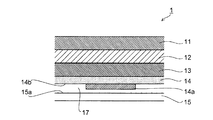
- FIG. 2 is a cross-sectional view of the mobile terminal 1.
- the mounting surface 14 a of the circuit board 14 is disposed facing the bottom surface 15 a of the cabinet 15, and the electronic component 14 a and the bottom surface 15 a are opposed to each other with a gap 7 therebetween.
- Air has a higher thermal resistance than the circuit board 14 and the metal plate 13.
- the amount of heat is likely to move in the direction of low thermal resistance.
- the heat generated from the electronic component 14a is transferred from the circuit board 14 to the metal plate 13 and the rechargeable battery 12 and hardly transferred to the bottom surface 15a of the facing cabinet 15. Therefore, it is possible to prevent the outer surface of the cabinet 15 from being locally heated by the heat generated in the electronic component 14a. Thereby, it can prevent that the outer surface of the cabinet 15 which a user contacts locally raises temperature.
- the heat transferred from the circuit board 14 to the metal plate 13 having a low thermal resistance is diffused in the surface direction and transferred to the rechargeable battery 12.
- the heat generated in the electronic component 14a can be prevented from being locally transferred to the rechargeable battery 12.
- the rechargeable battery 12 has a large heat capacity, and the heat transferred to the rechargeable battery 12 is stored in the rechargeable battery 12 and diffused. Thereby, it can prevent that the rechargeable battery 12 interrupts
- the heat dissipation of the electronic component 14a can be efficiently performed, and the deterioration of the performance of the electronic component 14a can be suppressed.
- the rechargeable battery 12 can be used to dissipate the electronic component 14a, and the manufacturing cost of the portable terminal 1 can be reduced.
- the heat generated from the electronic component 14 a is transferred from the circuit board 14 to the rechargeable battery 12.
- the rechargeable battery 12 has a large heat capacity, and the heat transferred is stored in the rechargeable battery 12 and diffused. Thereby, it can prevent that the rechargeable battery 12 interrupts
- the metal plate 13 between the rechargeable battery 12 and the circuit board 14, the heat generated from the electronic component 14 a is conducted to the metal plate 13. At this time, the metal plate 13 extends to the outer peripheral side with respect to the circuit board 14, and the heat transferred to the metal plate 13 diffuses in the surface direction. This prevents heat from being locally transferred from the electronic component 14a to the rechargeable battery 12.
- the mounting surface 14b of the circuit board 14 faces the bottom surface 15a of the cabinet 15, and the bottom surface 15a of the cabinet 15 and the electronic component 14b face each other with a gap 17 therebetween.
- Air has a higher thermal resistance than the circuit board 14 and the metal plate 13.
- the amount of heat is likely to move in the direction of low thermal resistance. For this reason, the heat generated from the electronic component 14 a is transferred from the circuit board 14 to the rechargeable battery 12, and is hardly transferred to the bottom surface 15 a of the facing cabinet 15. Therefore, the heat generated in the electronic component 14a is prevented from being locally transferred to the cabinet 14a. Thereby, it can prevent that the outer surface of the cabinet 15 which a user contacts locally raises temperature.
- the present invention can be widely used in various portable terminals such as communication devices, PDAs, schedule management devices, and game devices.
Landscapes
- Engineering & Computer Science (AREA)
- Theoretical Computer Science (AREA)
- Physics & Mathematics (AREA)
- Signal Processing (AREA)
- Microelectronics & Electronic Packaging (AREA)
- Computer Hardware Design (AREA)
- Human Computer Interaction (AREA)
- General Engineering & Computer Science (AREA)
- General Physics & Mathematics (AREA)
- Thermal Sciences (AREA)
- Cooling Or The Like Of Electrical Apparatus (AREA)
- Devices For Indicating Variable Information By Combining Individual Elements (AREA)
- Telephone Set Structure (AREA)
- Power Sources (AREA)
Abstract
Description
11 表示パネル
12 充電池
13 金属板
14 回路基板
14a 電子部品
14b 実装面
15 キャビネット
15a 底面
17 隙間
Claims (3)
- キャビネット内に配して電子部品を実装する回路基板と、前記キャビネットの開口面に配される表示パネルと、前記表示パネルと前記回路基板との間に配される充電池とを備えたことを特徴とする携帯端末。
- 前記回路基板よりも外周側に延びて前記充電池と前記回路基板との間に配される金属板を備えたことを特徴とする請求項1に記載の携帯端末。
- 前記キャビネットの底面に面して前記回路基板の実装面を配し、前記キャビネットの底面と前記電子部品とが隙間を介して対向することを特徴とする請求項1または請求項2に記載の携帯端末。
Priority Applications (2)
| Application Number | Priority Date | Filing Date | Title |
|---|---|---|---|
| US14/404,356 US9414529B2 (en) | 2012-08-01 | 2013-07-23 | Portable terminal |
| CN201380040742.0A CN104509230A (zh) | 2012-08-01 | 2013-07-23 | 便携式终端 |
Applications Claiming Priority (2)
| Application Number | Priority Date | Filing Date | Title |
|---|---|---|---|
| JP2012171041A JP2014032997A (ja) | 2012-08-01 | 2012-08-01 | 携帯端末 |
| JP2012-171041 | 2012-08-01 |
Publications (1)
| Publication Number | Publication Date |
|---|---|
| WO2014021143A1 true WO2014021143A1 (ja) | 2014-02-06 |
Family
ID=50027823
Family Applications (1)
| Application Number | Title | Priority Date | Filing Date |
|---|---|---|---|
| PCT/JP2013/069928 Ceased WO2014021143A1 (ja) | 2012-08-01 | 2013-07-23 | 携帯端末 |
Country Status (4)
| Country | Link |
|---|---|
| US (1) | US9414529B2 (ja) |
| JP (1) | JP2014032997A (ja) |
| CN (1) | CN104509230A (ja) |
| WO (1) | WO2014021143A1 (ja) |
Families Citing this family (5)
| Publication number | Priority date | Publication date | Assignee | Title |
|---|---|---|---|---|
| JP2016045399A (ja) * | 2014-08-25 | 2016-04-04 | カシオ計算機株式会社 | 放熱構造、及び電子機器 |
| JP6578471B2 (ja) * | 2015-02-27 | 2019-09-25 | 富士通クライアントコンピューティング株式会社 | 表示機器 |
| KR102543912B1 (ko) * | 2015-10-05 | 2023-06-15 | 삼성전자 주식회사 | 복수의 디스플레이를 구비한 전자장치 및 그 제어 방법 |
| CN111867292B (zh) * | 2020-07-27 | 2022-01-28 | 青岛海信移动通信技术股份有限公司 | 一种电子设备 |
| WO2025094381A1 (ja) * | 2023-11-02 | 2025-05-08 | 任天堂株式会社 | 電子機器 |
Citations (4)
| Publication number | Priority date | Publication date | Assignee | Title |
|---|---|---|---|---|
| JP2004013839A (ja) * | 2002-06-11 | 2004-01-15 | Fujitsu Ltd | 情報処理装置及びプリント基板 |
| WO2007125718A1 (ja) * | 2006-04-27 | 2007-11-08 | Kyocera Corporation | 電子機器 |
| WO2008062879A1 (fr) * | 2006-11-22 | 2008-05-29 | Kyocera Corporation | Dispositif électronique mobile |
| JP2012100034A (ja) * | 2010-11-01 | 2012-05-24 | Sharp Corp | 携帯端末のカバー及びそれを備えた携帯端末 |
Family Cites Families (25)
| Publication number | Priority date | Publication date | Assignee | Title |
|---|---|---|---|---|
| JP3671855B2 (ja) * | 2001-03-02 | 2005-07-13 | 秀 島▲ざき▼ | 携帯電話機 |
| SE0103835L (sv) * | 2001-11-02 | 2003-05-03 | Neonode Ab | Pekskärm realiserad av displayenhet med ljussändande och ljusmottagande enheter |
| JP2003229938A (ja) * | 2002-02-04 | 2003-08-15 | Matsushita Electric Ind Co Ltd | 折畳式携帯電話装置 |
| JP2005189512A (ja) * | 2003-12-25 | 2005-07-14 | Nec Corp | 電子機器における背面lcdの衝撃吸収構造および該構造を備えた電子機器 |
| JP4385252B2 (ja) * | 2003-12-25 | 2009-12-16 | 日本電気株式会社 | 電子機器におけるlcdの防塵構造および該構造を備えた電子機器 |
| US7274954B2 (en) * | 2004-06-21 | 2007-09-25 | Motorola, Inc. | Communication device including one or more electrical control buttons in an upper housing part |
| US7336228B2 (en) * | 2004-12-15 | 2008-02-26 | Kyocera Wireless Corp | Stack-up configuration for a wireless communication device |
| KR100598121B1 (ko) * | 2005-03-08 | 2006-07-07 | 삼성전자주식회사 | 휴대용 디스플레이장치 |
| CN1874658B (zh) * | 2005-06-03 | 2011-09-21 | 深圳富泰宏精密工业有限公司 | 携带式电子装置电池盖结构 |
| US20070021156A1 (en) * | 2005-07-19 | 2007-01-25 | Hoong Chow T | Compact radio communications device |
| US20080037769A1 (en) * | 2006-07-24 | 2008-02-14 | Motorola, Inc. | User interface substrate for handset device |
| JP2008198860A (ja) | 2007-02-14 | 2008-08-28 | Nec Corp | 小型携帯端末機器の冷却手段 |
| US8125791B2 (en) * | 2007-05-23 | 2012-02-28 | Kyocera Corporation | Portable electronic device |
| JP4828482B2 (ja) * | 2007-07-30 | 2011-11-30 | 京セラ株式会社 | 携帯無線装置 |
| JP4625063B2 (ja) * | 2007-09-25 | 2011-02-02 | 富士通株式会社 | 液晶表示装置を備えた電子機器 |
| KR101495157B1 (ko) * | 2007-11-27 | 2015-02-24 | 엘지전자 주식회사 | 휴대 단말기 |
| JP5127840B2 (ja) * | 2007-12-14 | 2013-01-23 | 富士通株式会社 | 表示パネル構造体、それを用いた電子装置、および携帯型情報機器 |
| CN101257526B (zh) * | 2008-04-07 | 2015-04-22 | Tcl天一移动通信(深圳)有限公司 | 一种移动通信终端的组合式电池盖侧面接地结构 |
| US8537543B2 (en) * | 2008-04-11 | 2013-09-17 | Apple Inc. | Portable electronic device housing structures |
| CN102106138A (zh) * | 2008-07-29 | 2011-06-22 | 京瓷株式会社 | 便携式电子设备 |
| KR20100046594A (ko) * | 2008-10-27 | 2010-05-07 | 엘지전자 주식회사 | 휴대 단말기 |
| KR101580189B1 (ko) * | 2009-05-21 | 2015-12-24 | 삼성전자주식회사 | 휴대 단말기의 안테나 장치 |
| KR101580126B1 (ko) * | 2009-07-21 | 2015-12-28 | 엘지전자 주식회사 | 이동 단말기 |
| JP2011155520A (ja) * | 2010-01-27 | 2011-08-11 | Kyocera Corp | 携帯電子機器 |
| US8872997B2 (en) * | 2010-08-31 | 2014-10-28 | Apple Inc. | Display assembly |
-
2012
- 2012-08-01 JP JP2012171041A patent/JP2014032997A/ja active Pending
-
2013
- 2013-07-23 WO PCT/JP2013/069928 patent/WO2014021143A1/ja not_active Ceased
- 2013-07-23 CN CN201380040742.0A patent/CN104509230A/zh active Pending
- 2013-07-23 US US14/404,356 patent/US9414529B2/en not_active Expired - Fee Related
Patent Citations (4)
| Publication number | Priority date | Publication date | Assignee | Title |
|---|---|---|---|---|
| JP2004013839A (ja) * | 2002-06-11 | 2004-01-15 | Fujitsu Ltd | 情報処理装置及びプリント基板 |
| WO2007125718A1 (ja) * | 2006-04-27 | 2007-11-08 | Kyocera Corporation | 電子機器 |
| WO2008062879A1 (fr) * | 2006-11-22 | 2008-05-29 | Kyocera Corporation | Dispositif électronique mobile |
| JP2012100034A (ja) * | 2010-11-01 | 2012-05-24 | Sharp Corp | 携帯端末のカバー及びそれを備えた携帯端末 |
Also Published As
| Publication number | Publication date |
|---|---|
| JP2014032997A (ja) | 2014-02-20 |
| CN104509230A (zh) | 2015-04-08 |
| US9414529B2 (en) | 2016-08-09 |
| US20150173247A1 (en) | 2015-06-18 |
Similar Documents
| Publication | Publication Date | Title |
|---|---|---|
| TWI437416B (zh) | 薄型被動冷卻系統 | |
| JP4498419B2 (ja) | 電子機器 | |
| US9148966B2 (en) | Electronic device | |
| WO2014021143A1 (ja) | 携帯端末 | |
| CN111342511A (zh) | 电子设备及控制方法、充电系统 | |
| CN103914108A (zh) | 便携设备和电子装置的框架结构 | |
| TWM469525U (zh) | 手持式行動裝置之散熱結構 | |
| WO2020052030A1 (zh) | 柔性电子装置 | |
| JP5991527B2 (ja) | 電池及び蓄電装置 | |
| US9244505B2 (en) | Portable electronic device with exposed heat dissipating mechanism | |
| JP2020003973A (ja) | 電子機器 | |
| US9277675B2 (en) | Electronic apparatus | |
| JP2010055642A (ja) | 電子機器 | |
| CN106455404B (zh) | 具断热之中框结构及电子设备 | |
| CN209861402U (zh) | 柔性电子装置 | |
| JP2015015545A (ja) | 携帯端末 | |
| US20100304202A1 (en) | Rechargeable battery | |
| CN209420182U (zh) | 电子装置 | |
| CN216531410U (zh) | 一种散热手机壳 | |
| JP2002008604A (ja) | 電子機器 | |
| JP2002093470A (ja) | 電池パック | |
| JP5048147B1 (ja) | 液晶表示装置 | |
| CN223692870U (zh) | 显示装置及手机 | |
| CN224111193U (zh) | 电子设备 | |
| JP7702033B1 (ja) | 電子機器 |
Legal Events
| Date | Code | Title | Description |
|---|---|---|---|
| 121 | Ep: the epo has been informed by wipo that ep was designated in this application |
Ref document number: 13825750 Country of ref document: EP Kind code of ref document: A1 |
|
| WWE | Wipo information: entry into national phase |
Ref document number: 14404356 Country of ref document: US |
|
| WWE | Wipo information: entry into national phase |
Ref document number: IDP00201500247 Country of ref document: ID |
|
| NENP | Non-entry into the national phase |
Ref country code: DE |
|
| 122 | Ep: pct application non-entry in european phase |
Ref document number: 13825750 Country of ref document: EP Kind code of ref document: A1 |