WO2014017546A1 - 電線保護部材 - Google Patents
電線保護部材 Download PDFInfo
- Publication number
- WO2014017546A1 WO2014017546A1 PCT/JP2013/070068 JP2013070068W WO2014017546A1 WO 2014017546 A1 WO2014017546 A1 WO 2014017546A1 JP 2013070068 W JP2013070068 W JP 2013070068W WO 2014017546 A1 WO2014017546 A1 WO 2014017546A1
- Authority
- WO
- WIPO (PCT)
- Prior art keywords
- corrugated tube
- positioning hole
- electric wire
- corrugated
- binding band
- Prior art date
- Legal status (The legal status is an assumption and is not a legal conclusion. Google has not performed a legal analysis and makes no representation as to the accuracy of the status listed.)
- Ceased
Links
Images





Classifications
-
- H—ELECTRICITY
- H01—ELECTRIC ELEMENTS
- H01B—CABLES; CONDUCTORS; INSULATORS; SELECTION OF MATERIALS FOR THEIR CONDUCTIVE, INSULATING OR DIELECTRIC PROPERTIES
- H01B7/00—Insulated conductors or cables characterised by their form
- H01B7/17—Protection against damage caused by external factors, e.g. sheaths or armouring
-
- H—ELECTRICITY
- H02—GENERATION; CONVERSION OR DISTRIBUTION OF ELECTRIC POWER
- H02G—INSTALLATION OF ELECTRIC CABLES OR LINES, OR OF COMBINED OPTICAL AND ELECTRIC CABLES OR LINES
- H02G3/00—Installations of electric cables or lines or protective tubing therefor in or on buildings, equivalent structures or vehicles
- H02G3/02—Details
- H02G3/04—Protective tubing or conduits, e.g. cable ladders or cable troughs
- H02G3/0462—Tubings, i.e. having a closed section
- H02G3/0468—Corrugated
-
- H—ELECTRICITY
- H01—ELECTRIC ELEMENTS
- H01R—ELECTRICALLY-CONDUCTIVE CONNECTIONS; STRUCTURAL ASSOCIATIONS OF A PLURALITY OF MUTUALLY-INSULATED ELECTRICAL CONNECTING ELEMENTS; COUPLING DEVICES; CURRENT COLLECTORS
- H01R13/00—Details of coupling devices of the kinds covered by groups H01R12/70 or H01R24/00 - H01R33/00
- H01R13/56—Means for preventing chafing or fracture of flexible leads at outlet from coupling part
-
- H—ELECTRICITY
- H01—ELECTRIC ELEMENTS
- H01R—ELECTRICALLY-CONDUCTIVE CONNECTIONS; STRUCTURAL ASSOCIATIONS OF A PLURALITY OF MUTUALLY-INSULATED ELECTRICAL CONNECTING ELEMENTS; COUPLING DEVICES; CURRENT COLLECTORS
- H01R13/00—Details of coupling devices of the kinds covered by groups H01R12/70 or H01R24/00 - H01R33/00
- H01R13/58—Means for relieving strain on wire connection, e.g. cord grip, for avoiding loosening of connections between wires and terminals within a coupling device terminating a cable
-
- H—ELECTRICITY
- H01—ELECTRIC ELEMENTS
- H01R—ELECTRICALLY-CONDUCTIVE CONNECTIONS; STRUCTURAL ASSOCIATIONS OF A PLURALITY OF MUTUALLY-INSULATED ELECTRICAL CONNECTING ELEMENTS; COUPLING DEVICES; CURRENT COLLECTORS
- H01R13/00—Details of coupling devices of the kinds covered by groups H01R12/70 or H01R24/00 - H01R33/00
- H01R13/58—Means for relieving strain on wire connection, e.g. cord grip, for avoiding loosening of connections between wires and terminals within a coupling device terminating a cable
- H01R13/582—Means for relieving strain on wire connection, e.g. cord grip, for avoiding loosening of connections between wires and terminals within a coupling device terminating a cable the cable being clamped between assembled parts of the housing
- H01R13/5825—Means for relieving strain on wire connection, e.g. cord grip, for avoiding loosening of connections between wires and terminals within a coupling device terminating a cable the cable being clamped between assembled parts of the housing the means comprising additional parts captured between housing parts and cable
-
- H—ELECTRICITY
- H01—ELECTRIC ELEMENTS
- H01R—ELECTRICALLY-CONDUCTIVE CONNECTIONS; STRUCTURAL ASSOCIATIONS OF A PLURALITY OF MUTUALLY-INSULATED ELECTRICAL CONNECTING ELEMENTS; COUPLING DEVICES; CURRENT COLLECTORS
- H01R13/00—Details of coupling devices of the kinds covered by groups H01R12/70 or H01R24/00 - H01R33/00
- H01R13/56—Means for preventing chafing or fracture of flexible leads at outlet from coupling part
- H01R13/567—Traverse cable outlet or wire connection
-
- H—ELECTRICITY
- H02—GENERATION; CONVERSION OR DISTRIBUTION OF ELECTRIC POWER
- H02G—INSTALLATION OF ELECTRIC CABLES OR LINES, OR OF COMBINED OPTICAL AND ELECTRIC CABLES OR LINES
- H02G3/00—Installations of electric cables or lines or protective tubing therefor in or on buildings, equivalent structures or vehicles
- H02G3/02—Details
- H02G3/08—Distribution boxes; Connection or junction boxes
- H02G3/088—Dustproof, splashproof, drip-proof, waterproof, or flameproof casings or inlets
Definitions
- the present invention relates to a wire protection member.
- a connector having a cover for fixing the corrugated tube to the connector housing is known so that corrugated tubes having different outer diameters can be properly fixed (see Patent Document 1 and the like).
- This type of connector is configured such that a separate connector housing and a connector cover 501 that is an electric wire protection member can be attached and detached.
- the connector cover 501 is provided with a fitting means 503 and a tube insertion portion 505.
- the fitting means 503 is locked with a locking means (not shown) of the connector housing and is fitted with the connector housing.
- the tube insertion part 505 is provided with a binding band restriction part 507, and the binding band restriction part 507 determines the binding position of the binding band (binding member) 513 by the first restriction wall 509 and the second restriction wall 511 (FIG. 8A). And FIG. 8B).
- the binding band contact portion 515 of the binding band regulating portion 507 is provided with two binding band passage holes 517 for passing the binding band 513 from the outside to the inside. Even if the connector cover 501 has the first corrugated tube 519 or the second corrugated tube 521 with different valley or peak pitches attached to the connector, the first cover projection 523 and the second latch projection 525 Is a common multiple of the respective pitches, so that different corrugated tubes can be properly locked to both the first locking protrusion 523 and the second locking protrusion 525.
- the outer diameter of the first corrugated tube 519 having a large size substantially matches the inner diameter of the opening on the right side of the tube insertion portion 505. Further, in a side view, the lower portion of the first corrugated tube 519 is largely exposed from the lower side of the tube insertion portion 505. Therefore, as shown in FIG. 8A, the binding band 513 can be appropriately fixed even if the first corrugated tube 519 is fixed around the outer periphery (substantially semicircular) of the tube insertion portion 505.
- the binding band 513 is passed through the binding band passage hole 517, and the binding band 513 is guided to the inside without turning the entire outer periphery, and the binding band 513 and the second corrugated tube 521 contact each other. Secure enough parts. Thereby, the second corrugated tube 521 can be appropriately fixed to the tube insertion portion 505.
- the binding band 513 to which the first corrugated tube 519 is fixed is held only by the binding band regulating part 507 and the binding band contact part 515. That is, since there is no structure for holding the binding band 513 on the opening side of the tube insertion portion 505, the binding band 513 may be detached from the binding band regulating portion 507 due to vibration.
- these two types of corrugated tubes having an outer diameter larger than the first corrugated tube 519 and the second corrugated tube 521 are used, it is difficult to hold them by the binding band 513.
- the present invention has been made in view of the above situation, and its purpose is to provide a good electric wire protection in which a plurality of types of corrugated tubes having different outer diameter sizes can be used, and the binding member does not come off from the binding member regulating portion. It is to provide a member.
- a main body that covers the periphery of an electric wire to be routed, and a semi-cylindrical corrugated tube fixing that is integrally formed with the main body and ends of plural types of corrugated tubes having different diameters through which the electric wire is inserted.
- a bundling member, and a bundling member restricting portion provided at both ends in the outer peripheral direction of the corrugated tube fixing portion to determine the position of the bundling member, wherein the bundling member restricting portion is in accordance with different diameters of the corrugated tube.
- An electric wire protection member having a plurality of positioning holes in which the bridge positions of the binding members are different.
- the corrugated tube whose end is arranged in the corrugated tube fixing portion is fixed to the corrugated tube fixing portion by the binding member.
- the position of the binding member is determined by the binding member restricting portions provided at both ends in the outer peripheral direction of the corrugated tube fixing portion.
- the binding member restricting portion is provided with a plurality of positioning hole portions in which the bridging position of the binding member differs depending on different diameters of the corrugated tube. That is, when fixing the corrugated tube of any outer diameter size, the bundling members are inserted into the positioning hole portions having the corresponding bridge positions, so that the dropping is reliably prevented.
- the corrugated tube fixing part has a plurality of positioning hole parts with different bridging positions of the bundling member provided in the bundling member regulating part, so that the corrugated tube of various types of outer diameters can be tightened and fixed well without crushing the bundling member. can do.
- the positioning hole corresponding to the corrugated tube having the maximum diameter is provided outside the positioning hole corresponding to the corrugated tube having another diameter. Therefore, the axial length of the bundling member restricting portion can be shortened as compared with the case where each positioning hole is provided along the axis of the corrugated tube.
- the positioning hole corresponding to the corrugated tube with the maximum diameter has the tip of the extension bridge wall at the bridge position, so the bundling member inserted into the positioning hole of this positioning hole is the tip of the extension bridge wall on both sides. And the upper side protruding from the semi-cylindrical corrugated tube fixing portion is pressed to fasten and fix the corrugated tube having the maximum diameter.
- the positioning hole corresponding to the corrugated tube with the largest diameter is tightened and fixed regardless of the position of the positioning hole because the bridging position of the bundling member is tangentially outward from the positioning hole by the extension of the extension bridge wall. The collapse of the corrugated tube with the largest diameter can be suppressed.
- the bundling member inserted into the positioning hole of the positioning hole corresponding to the corrugated tube having the maximum diameter is led out from the positioning hole and then to the tip of the extension bridge wall. Hang and fasten the corrugated tube of maximum diameter. If the corrugated tube with the maximum diameter is moved in the direction along the axis due to vibration or the like, the bundling member will also move along with this, but the positioning projection protruding from the end of the extension bridge wall will move the bundling member. It regulates and the detachment of the binding member from the tip of the extension bridge wall is surely prevented.
- FIG. 1A is a perspective view of an electric wire cover according to an embodiment of the present invention.
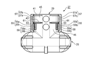
- 1B is a view of the wire cover shown in FIG. 1A as viewed from the direction of arrow A.
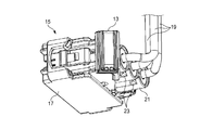
- FIG. FIG. 2A is a perspective view of the connector to which the wire cover shown in FIG. 1A is mounted as viewed from the wire lead-out side.
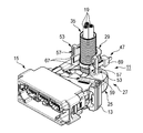
- 2B is a perspective view of the connector shown in FIG. 2A as viewed from the mating connector coupling side.
- 3A is a front view and a side view of the first corrugated tube
- FIG. 3B is a front view and a side view of the second corrugated tube
- FIG. 3C is a front view of the third corrugated tube.
- FIG. 4A is a perspective view of an electric wire cover to which the first corrugated tube is attached.
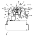
- 4B is a front view of the electric wire cover shown in FIG. 4A as viewed from the electric wire outlet side.
- FIG. 5A is a perspective view of an electric wire cover to which a second corrugated tube is attached.
- 5B is a front view of the electric wire cover shown in FIG. 5A as viewed from the electric wire outlet side.
- FIG. 6A is a perspective view of an electric wire cover to which a third corrugated tube is attached.
- FIG. 6B is a front view of the electric wire cover shown in FIG. 6A as viewed from the electric wire outlet side.
- FIG. 7A is a side view of a conventional wire protection member.
- FIG. 7B is a bottom view of the wire protection member shown in FIG. 7A.
- FIG. 8A is a bottom view of a conventional electric wire protection member to which the first corrugated tube is fixed.
- FIG. 8B is a bottom view of a conventional wire protection member to which the second corrugated tube is fixed.
- the electric wire protection member according to an embodiment of the present invention is used in, for example, the electric wire cover 11 and a harness protector.
- the case where the wire protection member is the wire cover 11 will be described as an example.
- the wire cover 11 can be applied to, for example, a low insertion force connector 15 which is a connector provided with a lever 13 for reducing insertion force with a mating connector (not shown) (see FIGS. 2A and 2B).
- the low insertion force connector 15 accommodates a plurality of terminals (not shown) in a connector housing 17.
- An electric wire 19 is connected to each terminal, and the electric wire 19 is led out from the housing rear portion 21 on the side opposite to the fitting side with the mating connector.
- a cover locking projection 23 for locking the wire cover 11 is formed on the housing rear portion 21 in the connector housing 17.
- led-out from the housing rear part 21 is covered with the electric wire cover 11 in the state bent in the direction orthogonal to a connector fitting direction (left-right direction of FIG. 2A). That is, the electric wire cover 11 constitutes an electric wire accommodation path bent in an L shape.
- the wire cover 11 includes a wire body 25 in which the cover body (main body) 27 houses the wire 19 immediately after being led out from the housing rear portion 21, and the wire housing portion 25. And a corrugated tube fixing portion 29 that covers the periphery of the electric wire 19 bent in the orthogonal direction from the electric wire accommodating portion 25. That is, the cover body 27 is integrally formed with a semi-cylindrical corrugated tube fixing portion 29.
- the corrugated tube fixing portion 29 can fix the end portions of a plurality of types of first to third corrugated tubes 35, 37 and 39 having different diameters through which the electric wire 19 is inserted.
- the plurality of electric wires 19 arranged inside the corrugated tube fixing portion 29 are collectively inserted into the corrugated tube. That is, the plurality of electric wires 19 are protected by any of the first to third corrugated tubes 35, 37, and 39.
- the first to third corrugated tubes 35, 37, 39 are made of synthetic resin, and as shown in FIGS. 3 (a) to 3 (c), circumferential protrusions 31 and an outer peripheral groove 33 are formed on the outer periphery. It has a bellows shape arranged alternately and has flexibility, and is configured to bend and deform while being curved.
- the first to third corrugated tubes 35, 37 and 39 surround the electric wire 19 led out from the housing rear portion 21, so that the electric wire 19 is protected without being exposed to the outside.
- the corrugated tube fixing portion 29 includes a first corrugated tube 35 having an outer diameter size D1, a second corrugated tube 37 having an outer diameter size D2, and a third corrugated tube having an outer diameter size D3. 39 can be fixed respectively.
- the size relationship of the outer diameter size is D1 ⁇ D2 ⁇ D3. More specifically, for example, the outer diameter size D1 can be 14.10 mm, the outer diameter size D2 can be 17.50 mm, and the outer diameter size D3 can be 19.50 mm.
- a first restricting wall 41 and a second restricting wall 43 are formed on the outer periphery of the corrugated tube fixing portion 29 so as to project in a bowl shape.
- a binding band contact portion 45 is formed between the first restriction wall 41 and the second restriction wall 43. That is, the 1st control wall 41 and the 2nd control wall 43 can control the binding position with respect to the outer peripheral surface of the corrugated tube fixing
- the binding band 47 restricted by the first restriction wall 41 or the second restriction wall 43 fastens and fixes the corrugated tube to the inner peripheral side of the corrugated tube fixing portion 29.
- a binding member restricting portion 53 that determines the position of the binding band 47 is provided at both ends 51 in the outer circumferential direction of the corrugated tube fixing portion 29 formed in a semi-cylindrical shape.
- the bundling member restricting portion 53 has a plurality of (three in the present embodiment) in which the bridging positions of the bundling band 47 differ according to the different outer diameters D1, D2, and D3 of the first to third corrugated tubes 35, 37, and 39.
- the first to third positioning holes 55, 57, 59 are provided.
- the first positioning hole portion 55 of the present embodiment has a first positioning hole 55a through which the binding band 47 is inserted corresponding to the first corrugated tube 35, and an inner opening edge 55b that serves as a bridge position of the binding band 47.
- the first positioning holes 55 a are formed in the respective wall portions of the outer peripheral end portions 51 along the tangential direction of the first corrugated tube 35. Therefore, the inner opening edge 55 b in the first positioning hole 55 a is a bridge position of the binding band 47 corresponding to the first corrugated tube 35.
- the second positioning hole portion 57 of the present embodiment has a second positioning hole 57a through which the binding band 47 is inserted corresponding to the second corrugated tube 37, and an inner opening edge 57b that serves as a bridge position of the binding band 47.
- the second positioning holes 57 a are formed along the tangential direction of the second corrugated tube 37 in the projecting portions 61 that project outward in the radial direction of the both ends 51 in the outer circumferential direction. Therefore, the inner opening edge 57 b in the second positioning hole 57 a is a bridge position of the binding band 47 corresponding to the second corrugated tube 37.
- the third positioning hole 59 of the present embodiment includes a third positioning hole 59a through which the binding band 47 is inserted corresponding to the third corrugated tube 39, and a distal end 59b of the extension bridge wall 65 that serves as a bridge position of the binding band 47. And have.
- the third positioning hole 59 a is formed along the tangential direction of the third corrugated tube 39 in the projecting portion 61 that projects outward in the radial direction of the both ends 51 in the outer circumferential direction.
- the leading end 59b of the extended bridge wall 65 extending from the inner opening edge of the third positioning hole 59a along the tangential direction of the third corrugated tube 39 is the bridge position of the binding band 47 corresponding to the third corrugated tube 39. It becomes.
- the first to third positioning holes 55, 57, 59 are arranged so that the bridging position of the binding band 47 is tangential to each corrugated tube according to the outer diameter size of the first to third corrugated tubes 35, 37, 39. It is configured to move forward along different. Therefore, the corrugated tube fixing portion 29 can satisfactorily fix the first to third corrugated tubes 35, 37, and 39 having different outer diameter sizes without causing the binding band 47 to be crushed.
- the second positioning hole 57a and the third positioning hole 59a of the present embodiment are formed in the protruding portion 61 protruding outward in the radial direction of the both ends 51 in the outer circumferential direction, side by side in the direction along the axis of the corrugated tube.
- the second positioning hole 57a and the third positioning hole 59a are partitioned by the partition wall 63.
- the third positioning hole 59 corresponding to the third corrugated tube 39 which is the corrugated tube having the maximum diameter is located outside the first positioning hole 55 corresponding to the first corrugated tube 35 which is the corrugated tube having another diameter. Is provided. Further, a positioning projection 67 for positioning the binding band 47 is projected from the tip 59b of the extended bridge wall 65 extending from the inner opening edge of the third positioning hole 59a.
- the operation of the wire cover 11 having the above configuration will be described.
- the end of the first corrugated tube 35 is engaged with the engaging protrusion 49 (see FIGS. 1A and 1B). It is engaged and disposed on the corrugated tube fixing portion 29.
- the first corrugated tube 35 is fastened to the corrugated tube fixing portion 29 by the binding band 47 inserted into the first positioning hole portion 55 of the binding member restricting portion 53 provided at both ends 51 in the outer circumferential direction of the corrugated tube fixing portion 29. Fixed.
- the band leading end side of the binding band 47 is passed from one side of the first positioning hole 55a in the first positioning hole portion 55, the outer periphery of the first corrugated tube 35 is rotated, and the first positioning hole 55a on the opposite side is passed. Thereafter, the first corrugated tube 35 is fixed to the corrugated tube fixing portion 29 by turning the binding band contact portion 45 (see FIGS. 1A and 1B) and passing the band leading end side through the buckle portion 69 of the binding band 47.
- the second corrugated tube 37 When the second corrugated tube 37 is fixed to the wire cover 11, as shown in FIGS. 5A and 5B, the end of the second corrugated tube 37 is engaged with the engaging protrusion 49 (see FIGS. 1A and 1B). It is engaged and disposed on the corrugated tube fixing portion 29. Then, the second corrugated tube 37 is fastened and fixed to the corrugated tube fixing portion 29 by the binding band 47 inserted through the second positioning hole portion 57 of the binding member regulating portion 53. More specifically, the band leading end side of the binding band 47 is passed from one side of the second positioning hole 57a in the second positioning hole portion 57, the outer periphery of the second corrugated tube 37 is rotated, and the second positioning hole 57a on the opposite side is passed. Then, the second corrugated tube 37 is fixed to the corrugated tube fixing portion 29 by turning the binding band contact portion 45 (see FIGS. 1A and 1B) and passing the band leading end side through the buckle portion 69 of the binding band 47
- the end of the third corrugated tube 39 is engaged with the engaging protrusion 49 (see FIGS. 1A and 1B). It is engaged and disposed on the corrugated tube fixing portion 29. Then, the third corrugated tube 39 is fastened and fixed to the corrugated tube fixing portion 29 by the binding band 47 inserted through the third positioning hole portion 59 of the binding member restricting portion 53. Specifically, after passing the band tip side of the binding band 47 from one side of the third positioning hole 59a in the third positioning hole 59, along the extension bridge wall 65, the outer periphery of the third corrugated tube 39 is turned, and the extension bridge is again formed.
- the binding band contact portion 45 (see FIGS. 1A and 1B) is rotated, and the band leading end side is passed through the buckle portion 69 of the binding band 47.
- the third corrugated tube 39 is fixed to the corrugated tube fixing portion 29.
- the first to third corrugated tubes 35, 37, and 39 whose ends are arranged on the corrugated tube fixing portion 29 are connected to the corrugated tube fixing portion 29 by the binding band 47. Fixed to. At this time, the position of the binding band 47 is determined by the binding member restricting portions 53 provided at both ends 51 in the outer peripheral direction of the corrugated tube fixing portion 29.
- the binding member restricting portion 53 includes first to third positioning hole portions 55 in which the bridging position of the binding band 47 differs depending on the different outer diameters D1, D2, and D3 of the first to third corrugated tubes 35, 37, and 39. , 57, 59 are provided.
- the binding band 47 has first to third positioning positions each having a corresponding bridge position.
- the corrugated tube fixing part 29 is provided with the first to third positioning holes 55, 57, 59 having different bridging positions of the binding band 47 in the binding member restricting part 53, so that three types of outer diameter sizes D1, The first to third corrugated tubes 35, 37 and 39 of D2 and D3 can be firmly tightened and fixed without the binding band 47 being crushed.
- the third positioning hole portion 59 corresponding to the third corrugated tube 39 is provided outside the first positioning hole portion 55 corresponding to the first corrugated tube 35. . Therefore, the axial length of the bundling member restricting portion 53 can be shortened, and the enlargement of the wire cover 11 can be suppressed as compared with the case where each positioning hole portion is provided along the axis of the corrugated tube.
- the end 59b of the extension bridge wall 65 is set as the bridge position of the binding band 47. Therefore, the binding band 47 inserted into the third positioning hole 59a of the third positioning hole 59 is stretched over the tip 59b of the extension bridge wall 65 on both sides and protrudes from the semi-cylindrical corrugated tube fixing part 29. The upper side to be pressed is pressed and the third corrugated tube 39 is fastened and fixed.
- the bridging position of the binding band 47 is tangentially outside the third positioning hole 59 a by the extension of the extension bridge wall 65. Therefore, it is possible to suppress the third corrugated tube 39 from being crushed regardless of the position of the third positioning hole 59a.
- the third positioning hole 59a is located at the same position as the second positioning hole 57a of the second positioning hole 57, but the bridging position of the binding band 47 is the extension of the extension bridge wall 65. Only on the outer side in the tangential direction than the bridging position in the second positioning hole 57. Therefore, the third corrugated tube 39 that is fastened and fixed is not crushed.
- the binding band 47 inserted through the third positioning hole 59a of the third positioning hole 59 corresponding to the third corrugated tube 39 is led out from the third positioning hole 59a, and then the tip 59b ( The third corrugated tube 39 is tightened and fixed by being hung on (see FIGS. 1A and 1B).
- the binding band 47 also tries to move along with this, but the positioning projection 67 protruding from the tip 59b of the extension bridge wall 65 is bound. The movement of the band 47 is restricted. Therefore, the binding band 47 is reliably prevented from falling off from the tip 59b of the extension bridge wall 65.
- the first to third corrugated tubes 35, 37, and 39 having three types of outer diameters D1, D2, and D3 can be used, and the binding band 47 is bound. There is no detachment from the member restricting portion 53.
- the electric wire having a plurality of positioning hole portions (first to third positioning hole portions) 55a, 57a, and 59b having different bridge positions (inner opening edges and tips) 55b, 57b, and 59a of the binding member (binding band) 47.
- the electric wire protection member (electric wire cover) 11 having the configuration of [1] above, and the positioning hole portion (third positioning hole portion) 59 corresponding to the corrugated tube (third corrugated tube) 39 having the maximum diameter. Is provided outside the positioning hole portion (first positioning hole portion) 55 corresponding to the corrugated tube (first corrugated tube) 35 having another diameter, and is tangent to the corrugated tube (third corrugated tube) 39.
- the electric wire protection member (electric wire cover) 11 which has the extended bridge wall 65 extended along the direction. [3] The electric wire protection member (electric wire cover) 11 having the above-described configuration [2], and a positioning projection 67 for positioning the binding member (binding band) 47 is provided at the front end 59b of the extension bridge wall 65. An electric wire protection member (electric wire cover) 11.
- the electric wire protection member of this invention is not limited to embodiment mentioned above, A deformation
- the material, shape, dimensions, number, arrangement location, and the like of each component in the above-described embodiment are arbitrary and are not limited as long as the present invention can be achieved.
- the electric wire cover 11 has been described as an example of the electric wire protection member in the above embodiment, it is needless to say that the electric wire cover 11 can be applied to various electric wire protection members such as a harness protector provided with a corrugated tube fixing portion and an electric junction box. This application is based on a Japanese patent application filed on July 25, 2012 (Japanese Patent Application No. 2012-165183), the contents of which are incorporated herein by reference.
- the electric wire protection member According to the electric wire protection member according to the present invention, a plurality of types of corrugated tubes having different outer diameter sizes can be used, and the binding member does not come off the binding member restricting portion.
Landscapes
- Engineering & Computer Science (AREA)
- Architecture (AREA)
- Civil Engineering (AREA)
- Structural Engineering (AREA)
- Details Of Connecting Devices For Male And Female Coupling (AREA)
- Details Of Indoor Wiring (AREA)
- Installation Of Indoor Wiring (AREA)
Description
この種のコネクタは、別体のコネクタハウジングと電線保護部材であるコネクタカバー501とが着脱可能に構成されている。図7A及び図7Bに示すように、コネクタカバー501には、嵌合手段503及びチューブ挿入部505が設けられる。嵌合手段503は、コネクタハウジングの図示しない係止手段と係止されてコネクタハウジングと嵌合される。チューブ挿入部505には、結束バンド規制部507が設けられ、結束バンド規制部507は第1規制壁509と第2規制壁511とによって結束バンド(結束部材)513の結束位置を定める(図8A及び図8B参照)。
また、これら2種類の第1コルゲートチューブ519及び第2コルゲートチューブ521より大きい外径サイズのコルゲートチューブを使用する場合、結束バンド513による保持が困難となる。
(1) 配索される電線の周囲を覆う本体と、前記本体に一体形成されて前記電線を挿通する径の異なる複数種のコルゲートチューブの端部がそれぞれ固定される半円筒状のコルゲートチューブ固定部と、前記コルゲートチューブ固定部の内周方向に突設されて前記コルゲートチューブの外周溝に係合する係合突条と、前記コルゲートチューブ固定部の内周側に前記コルゲートチューブを緊締固定する結束部材と、前記コルゲートチューブ固定部の外周方向両端部に設けられて前記結束部材の位置を定める結束部材規制部と、を備え、前記結束部材規制部が、前記コルゲートチューブの異なる径に応じて前記結束部材の橋架位置が異なる複数の位置決め孔部を有する電線保護部材。
なお、最大径のコルゲートチューブに対応する位置決め孔部は、延長橋架壁の先端が橋架位置とされるので、この位置決め孔部の位置決め孔に挿通された結束部材は、両側の延長橋架壁の先端に架け渡されて、半円筒状のコルゲートチューブ固定部から突出する上側を押圧して最大径のコルゲートチューブを緊締固定する。ここで、最大径のコルゲートチューブに対応する位置決め孔部は、結束部材の架橋位置が延長橋架壁の延出分だけ位置決め孔より接線方向外側となるので、位置決め孔の位置に関わらず緊締固定される最大径のコルゲートチューブの潰れを抑制できる。
本発明の一実施形態に係る電線保護部材は、例えば電線カバー11やハーネスプロテクタ等に用いられる。本実施形態では、電線保護部材が電線カバー11である場合を例に説明する。電線カバー11は、図示しない相手コネクタとの挿入力を低減するためのレバー13を備えたコネクタである例えば低挿入力コネクタ15に適用することができる(図2A及び図2B参照)。
コルゲートチューブ固定部29の内周方向には、半円弧上の係合突条49が平行に一対突設されており、係合突条49はコルゲートチューブの外周溝33に係合する。これにより、係合突条49に係合された第1~第3コルゲートチューブ35,37,39は、軸線方向に移動不能に係止される。
電線カバー11に第1コルゲートチューブ35が固定される際には、図4A及び図4Bに示すように、第1コルゲートチューブ35の端部が係合突条49(図1A及び図1B参照)に係合されてコルゲートチューブ固定部29に配置される。そして、コルゲートチューブ固定部29の外周方向両端部51に設けられた結束部材規制部53の第1位置決め孔部55に挿通した結束バンド47によって、第1コルゲートチューブ35がコルゲートチューブ固定部29に緊締固定される。詳細には、第1位置決め孔部55における第1位置決め孔55aの片側から結束バンド47のバンド先端側を通し、第1コルゲートチューブ35の外周を回し、反対側の第1位置決め孔55aへ通した後、結束バンド接触部45(図1A及び図1B参照)を回し、結束バンド47のバックル部69にバンド先端側を通すことで、第1コルゲートチューブ35がコルゲートチューブ固定部29に固定される。
結束部材規制部53には、第1~第3コルゲートチューブ35,37,39の異なる外径サイズD1,D2,D3に応じて結束バンド47の橋架位置が異なる第1~第3位置決め孔部55,57,59が設けられている。即ち、いずれの外径サイズサイズD1,D2,D3の第1~第3コルゲートチューブ35,37,39を固定する際も、結束バンド47はそれぞれ対応する橋架位置を備えた第1~第3位置決め孔部55,57,59に挿通されることよって、脱落が確実に阻止される。従って、コルゲートチューブ固定部29は、結束バンド47の橋架位置が異なる第1~第3位置決め孔部55,57,59が結束部材規制部53に設けられることにより、3種類の外径サイズD1,D2,D3の第1~第3コルゲートチューブ35,37,39を結束バンド47が潰すことなく良好に緊締固定することができる。
[1] 配索される電線19の周囲を覆う本体(カバー本体)27と、前記本体(カバー本体)27に一体形成されて前記電線19を挿通する径の異なる複数種のコルゲートチューブ(第1~第3コルゲートチューブ)35,37,39の端部がそれぞれ固定される半円筒状のコルゲートチューブ固定部29と、前記コルゲートチューブ固定部29の内周方向に突設されて前記コルゲートチューブ(第1~第3コルゲートチューブ)35,37,39の外周溝33に係合する係合突条49と、前記コルゲートチューブ固定部29の内周側に前記コルゲートチューブ(第1~第3コルゲートチューブ)35,37,39を緊締固定する結束部材(結束バンド)47と、前記コルゲートチューブ固定部29の外周方向両端部51に設けられて前記結束部材(結束バンド)47の位置を定める結束部材規制部53と、を備え、前記結束部材規制部53が、前記コルゲートチューブ(第1~第3コルゲートチューブ)35,37,39の異なる径に応じて前記結束部材(結束バンド)47の橋架位置(内側開口縁及び先端)55b,57b,59aが異なる複数の位置決め孔部(第1~第3位置決め孔部)55a,57a,59bを有する電線保護部材(電線カバー)11。
[2] 上記[1]の構成の電線保護部材(電線カバー)11であって、最大径の前記コルゲートチューブ(第3コルゲートチューブ)39に対応する前記位置決め孔部(第3位置決め孔部)59が、他の径の前記コルゲートチューブ(第1コルゲートチューブ)35に対応する前記位置決め孔部(第1位置決め孔部)55の外側に設けられると共に、前記コルゲートチューブ(第3コルゲートチューブ)39の接線方向に沿って延設された延長橋架壁65を有する電線保護部材(電線カバー)11。
[3] 上記[2]の構成の電線保護部材(電線カバー)11であって、前記延長橋架壁65の先端59bには、前記結束部材(結束バンド)47を位置決めする位置決め突起67が突設されている電線保護部材(電線カバー)11。
例えば、上記実施形態では電線保護部材として電線カバー11を例に説明したが、コルゲートチューブ固定部を備えたハーネスプロテクタや電気接続箱等の種々の電線保護部材に適用できることは云うまでもない。
また、本出願は、2012年7月25日出願の日本特許出願(特願2012-165183)に基づくものであり、その内容はここに参照として取り込まれる。
19…電線
27…カバー本体(本体)
29…コルゲートチューブ固定部
33…外周溝
35…第1コルゲートチューブ(他の径のコルゲートチューブ)
37…第2コルゲートチューブ
39…第3コルゲートチューブ(最大径のコルゲートチューブ)
47…結束バンド(結束部材)
49…係合突条
51…外周方向両端部
53…結束部材規制部
55…第1位置決め孔部(位置決め孔部)
55a…第1位置決め孔
55b…内側開口縁(橋架位置)
57…第2位置決め孔部(位置決め孔部)
57a…第2位置決め孔
57b…内側開口縁(橋架位置)
59…第3位置決め孔部(位置決め孔部)
59a…第3位置決め孔
59b…先端(橋架位置)
65…延長橋架壁
67…位置決め突起
Claims (3)
- 配索される電線の周囲を覆う本体と、
前記本体に一体形成されて前記電線を挿通する径の異なる複数種のコルゲートチューブの端部がそれぞれ固定される半円筒状のコルゲートチューブ固定部と、
前記コルゲートチューブ固定部の内周方向に突設されて前記コルゲートチューブの外周溝に係合する係合突条と、
前記コルゲートチューブ固定部の内周側に前記コルゲートチューブを緊締固定する結束部材と、
前記コルゲートチューブ固定部の外周方向両端部に設けられて前記結束部材の位置を定める結束部材規制部と、を備え、
前記結束部材規制部が、前記コルゲートチューブの異なる径に応じて前記結束部材の橋架位置が異なる複数の位置決め孔部を有する電線保護部材。 - 請求項1記載の電線保護部材であって、
最大径の前記コルゲートチューブに対応する前記位置決め孔部が、他の径の前記コルゲートチューブに対応する前記位置決め孔部の外側に設けられると共に、前記コルゲートチューブの接線方向に沿って延設された延長橋架壁を有する電線保護部材。 - 請求項2記載の電線保護部材であって、
前記延長橋架壁の先端には、前記結束部材を位置決めする位置決め突起が突設されている電線保護部材。
Priority Applications (5)
| Application Number | Priority Date | Filing Date | Title |
|---|---|---|---|
| KR20157001772A KR20150023860A (ko) | 2012-07-25 | 2013-07-24 | 전선 보호 부재 |
| US14/401,765 US9412494B2 (en) | 2012-07-25 | 2013-07-24 | Electrical-wire-protecting member |
| DE112013003678.9T DE112013003678B4 (de) | 2012-07-25 | 2013-07-24 | Draht-Schutzelement |
| GB1420527.2A GB2518992A (en) | 2012-07-25 | 2013-07-24 | Electrical-wire-protecting member |
| CN201380039691.XA CN104488153B (zh) | 2012-07-25 | 2013-07-24 | 电线保护部件 |
Applications Claiming Priority (2)
| Application Number | Priority Date | Filing Date | Title |
|---|---|---|---|
| JP2012165183A JP5898013B2 (ja) | 2012-07-25 | 2012-07-25 | 電線保護部材 |
| JP2012-165183 | 2012-07-25 |
Publications (1)
| Publication Number | Publication Date |
|---|---|
| WO2014017546A1 true WO2014017546A1 (ja) | 2014-01-30 |
Family
ID=49997355
Family Applications (1)
| Application Number | Title | Priority Date | Filing Date |
|---|---|---|---|
| PCT/JP2013/070068 Ceased WO2014017546A1 (ja) | 2012-07-25 | 2013-07-24 | 電線保護部材 |
Country Status (7)
| Country | Link |
|---|---|
| US (1) | US9412494B2 (ja) |
| JP (1) | JP5898013B2 (ja) |
| KR (1) | KR20150023860A (ja) |
| CN (1) | CN104488153B (ja) |
| DE (1) | DE112013003678B4 (ja) |
| GB (1) | GB2518992A (ja) |
| WO (1) | WO2014017546A1 (ja) |
Cited By (2)
| Publication number | Priority date | Publication date | Assignee | Title |
|---|---|---|---|---|
| CN106711885A (zh) * | 2016-12-28 | 2017-05-24 | 重庆长安汽车股份有限公司 | 汽车线束分线盒 |
| US20170229850A1 (en) * | 2016-02-08 | 2017-08-10 | Sumitomo Wiring Systems, Ltd. | Electrical wire cover |
Families Citing this family (10)
| Publication number | Priority date | Publication date | Assignee | Title |
|---|---|---|---|---|
| JP5934595B2 (ja) * | 2012-07-25 | 2016-06-15 | 矢崎総業株式会社 | 電線保護部材 |
| JP2017059421A (ja) * | 2015-09-17 | 2017-03-23 | 住友電装株式会社 | 電線カバー |
| JP2017059428A (ja) * | 2015-09-17 | 2017-03-23 | 住友電装株式会社 | 電線カバー |
| JP6648661B2 (ja) * | 2015-10-07 | 2020-02-14 | 住友電装株式会社 | プロテクタ付ワイヤーハーネス |
| JP6324364B2 (ja) * | 2015-12-11 | 2018-05-16 | 矢崎総業株式会社 | コネクタのワイヤカバー |
| EP3376606B1 (en) * | 2017-03-17 | 2021-05-05 | Aptiv Technologies Limited | Cable harness plug |
| US10211562B2 (en) | 2017-06-01 | 2019-02-19 | Lear Corporation | Electrical connector assembly |
| JP2022022884A (ja) * | 2020-07-10 | 2022-02-07 | 矢崎総業株式会社 | ワイヤハーネス止水構造 |
| CN118591946A (zh) * | 2022-01-30 | 2024-09-03 | 理想工业公司 | 具有高进入防护的电连接器 |
| DE102022003815A1 (de) * | 2022-10-15 | 2024-04-18 | Deutz Aktiengesellschaft | Elektrische Verteilerbox |
Citations (3)
| Publication number | Priority date | Publication date | Assignee | Title |
|---|---|---|---|---|
| JP2002343497A (ja) * | 2001-05-15 | 2002-11-29 | Sumitomo Wiring Syst Ltd | 電線カバー |
| JP2004023897A (ja) * | 2002-06-17 | 2004-01-22 | Sumitomo Wiring Syst Ltd | 電気接続箱 |
| JP2010055863A (ja) * | 2008-08-27 | 2010-03-11 | Yazaki Corp | カバー付コネクタ |
Family Cites Families (4)
| Publication number | Priority date | Publication date | Assignee | Title |
|---|---|---|---|---|
| JP4835512B2 (ja) | 2007-05-21 | 2011-12-14 | 住友電装株式会社 | 電線カバー |
| JP5075488B2 (ja) | 2007-06-06 | 2012-11-21 | 矢崎総業株式会社 | コネクタ |
| US7915542B2 (en) * | 2007-07-09 | 2011-03-29 | Forbis Robert C | Electrical cable support bracket |
| JP2012165183A (ja) | 2011-02-07 | 2012-08-30 | Nikon Corp | 撮影装置 |
-
2012
- 2012-07-25 JP JP2012165183A patent/JP5898013B2/ja not_active Expired - Fee Related
-
2013
- 2013-07-24 KR KR20157001772A patent/KR20150023860A/ko not_active Withdrawn
- 2013-07-24 DE DE112013003678.9T patent/DE112013003678B4/de not_active Expired - Fee Related
- 2013-07-24 GB GB1420527.2A patent/GB2518992A/en not_active Withdrawn
- 2013-07-24 WO PCT/JP2013/070068 patent/WO2014017546A1/ja not_active Ceased
- 2013-07-24 US US14/401,765 patent/US9412494B2/en active Active
- 2013-07-24 CN CN201380039691.XA patent/CN104488153B/zh active Active
Patent Citations (3)
| Publication number | Priority date | Publication date | Assignee | Title |
|---|---|---|---|---|
| JP2002343497A (ja) * | 2001-05-15 | 2002-11-29 | Sumitomo Wiring Syst Ltd | 電線カバー |
| JP2004023897A (ja) * | 2002-06-17 | 2004-01-22 | Sumitomo Wiring Syst Ltd | 電気接続箱 |
| JP2010055863A (ja) * | 2008-08-27 | 2010-03-11 | Yazaki Corp | カバー付コネクタ |
Cited By (2)
| Publication number | Priority date | Publication date | Assignee | Title |
|---|---|---|---|---|
| US20170229850A1 (en) * | 2016-02-08 | 2017-08-10 | Sumitomo Wiring Systems, Ltd. | Electrical wire cover |
| CN106711885A (zh) * | 2016-12-28 | 2017-05-24 | 重庆长安汽车股份有限公司 | 汽车线束分线盒 |
Also Published As
| Publication number | Publication date |
|---|---|
| US20150179301A1 (en) | 2015-06-25 |
| CN104488153B (zh) | 2017-12-26 |
| US9412494B2 (en) | 2016-08-09 |
| DE112013003678T5 (de) | 2015-04-16 |
| CN104488153A (zh) | 2015-04-01 |
| JP5898013B2 (ja) | 2016-04-06 |
| KR20150023860A (ko) | 2015-03-05 |
| JP2014027755A (ja) | 2014-02-06 |
| GB2518992A (en) | 2015-04-08 |
| DE112013003678B4 (de) | 2023-05-17 |
| GB201420527D0 (en) | 2014-12-31 |
Similar Documents
| Publication | Publication Date | Title |
|---|---|---|
| JP5898013B2 (ja) | 電線保護部材 | |
| JP6508015B2 (ja) | ワイヤーハーネス、電線保護部材及び電線ホルダ | |
| CN103314492B (zh) | 线束保护器 | |
| US9539959B2 (en) | Structure for attaching band clip to corrugated tube | |
| JP5892427B2 (ja) | ホルダ及びこれを用いた編組線の端末接続構造 | |
| JP6701524B2 (ja) | 電線取付部材、電線付き電線取付部材、及び、コネクタ | |
| US20170085067A1 (en) | Wire cover | |
| JP5418514B2 (ja) | ワイヤハーネス用のプロテクタ | |
| JP6052131B2 (ja) | コルゲートチューブへのバンドクリップ取付構造 | |
| JP6083344B2 (ja) | ノイズ吸収具 | |
| CN104508914B (zh) | 电线保护部件 | |
| CN103636088A (zh) | 带有路径维持构件的波纹管以及线束 | |
| JP4830770B2 (ja) | 電線ホルダ | |
| JP2018201284A (ja) | 車体固定用クリップ及びワイヤハーネス | |
| JP7643258B2 (ja) | ワイヤハーネス及びプロテクタ | |
| JP5934500B2 (ja) | 電線カバー | |
| JP6920879B2 (ja) | ワイヤカバーおよびコネクタ | |
| WO2022168947A1 (ja) | グロメット | |
| JP6685099B2 (ja) | ワイヤハーネス | |
| JP2012182940A (ja) | バンドクリップ | |
| JP6570278B2 (ja) | コネクタ構造 | |
| JP2024114029A (ja) | プロテクタおよびワイヤハーネス | |
| JP2023015050A (ja) | 電気接続箱 | |
| KR20170021105A (ko) | 콜게이트 튜브 | |
| KR20190011874A (ko) | 멀티박스용 인출부 고정장치 |
Legal Events
| Date | Code | Title | Description |
|---|---|---|---|
| 121 | Ep: the epo has been informed by wipo that ep was designated in this application |
Ref document number: 13823775 Country of ref document: EP Kind code of ref document: A1 |
|
| WWE | Wipo information: entry into national phase |
Ref document number: 14401765 Country of ref document: US |
|
| ENP | Entry into the national phase |
Ref document number: 1420527 Country of ref document: GB Kind code of ref document: A Free format text: PCT FILING DATE = 20130724 |
|
| WWE | Wipo information: entry into national phase |
Ref document number: 1420527.2 Country of ref document: GB |
|
| ENP | Entry into the national phase |
Ref document number: 20157001772 Country of ref document: KR Kind code of ref document: A |
|
| WWE | Wipo information: entry into national phase |
Ref document number: 112013003678 Country of ref document: DE Ref document number: 1120130036789 Country of ref document: DE |
|
| 122 | Ep: pct application non-entry in european phase |
Ref document number: 13823775 Country of ref document: EP Kind code of ref document: A1 |