WO2014013946A1 - Module de connexion de batterie - Google Patents
Module de connexion de batterie Download PDFInfo
- Publication number
- WO2014013946A1 WO2014013946A1 PCT/JP2013/069122 JP2013069122W WO2014013946A1 WO 2014013946 A1 WO2014013946 A1 WO 2014013946A1 JP 2013069122 W JP2013069122 W JP 2013069122W WO 2014013946 A1 WO2014013946 A1 WO 2014013946A1
- Authority
- WO
- WIPO (PCT)
- Prior art keywords
- connector
- terminal
- unit cell
- electric wire
- holding
- Prior art date
Links
Images
Classifications
-
- H—ELECTRICITY
- H01—ELECTRIC ELEMENTS
- H01M—PROCESSES OR MEANS, e.g. BATTERIES, FOR THE DIRECT CONVERSION OF CHEMICAL ENERGY INTO ELECTRICAL ENERGY
- H01M10/00—Secondary cells; Manufacture thereof
- H01M10/42—Methods or arrangements for servicing or maintenance of secondary cells or secondary half-cells
- H01M10/48—Accumulators combined with arrangements for measuring, testing or indicating the condition of cells, e.g. the level or density of the electrolyte
- H01M10/482—Accumulators combined with arrangements for measuring, testing or indicating the condition of cells, e.g. the level or density of the electrolyte for several batteries or cells simultaneously or sequentially
-
- H—ELECTRICITY
- H01—ELECTRIC ELEMENTS
- H01M—PROCESSES OR MEANS, e.g. BATTERIES, FOR THE DIRECT CONVERSION OF CHEMICAL ENERGY INTO ELECTRICAL ENERGY
- H01M50/00—Constructional details or processes of manufacture of the non-active parts of electrochemical cells other than fuel cells, e.g. hybrid cells
- H01M50/20—Mountings; Secondary casings or frames; Racks, modules or packs; Suspension devices; Shock absorbers; Transport or carrying devices; Holders
- H01M50/298—Mountings; Secondary casings or frames; Racks, modules or packs; Suspension devices; Shock absorbers; Transport or carrying devices; Holders characterised by the wiring of battery packs
-
- H—ELECTRICITY
- H01—ELECTRIC ELEMENTS
- H01M—PROCESSES OR MEANS, e.g. BATTERIES, FOR THE DIRECT CONVERSION OF CHEMICAL ENERGY INTO ELECTRICAL ENERGY
- H01M50/00—Constructional details or processes of manufacture of the non-active parts of electrochemical cells other than fuel cells, e.g. hybrid cells
- H01M50/50—Current conducting connections for cells or batteries
- H01M50/502—Interconnectors for connecting terminals of adjacent batteries; Interconnectors for connecting cells outside a battery casing
- H01M50/505—Interconnectors for connecting terminals of adjacent batteries; Interconnectors for connecting cells outside a battery casing comprising a single busbar
-
- H—ELECTRICITY
- H01—ELECTRIC ELEMENTS
- H01M—PROCESSES OR MEANS, e.g. BATTERIES, FOR THE DIRECT CONVERSION OF CHEMICAL ENERGY INTO ELECTRICAL ENERGY
- H01M50/00—Constructional details or processes of manufacture of the non-active parts of electrochemical cells other than fuel cells, e.g. hybrid cells
- H01M50/50—Current conducting connections for cells or batteries
- H01M50/502—Interconnectors for connecting terminals of adjacent batteries; Interconnectors for connecting cells outside a battery casing
- H01M50/514—Methods for interconnecting adjacent batteries or cells
- H01M50/517—Methods for interconnecting adjacent batteries or cells by fixing means, e.g. screws, rivets or bolts
-
- H—ELECTRICITY
- H01—ELECTRIC ELEMENTS
- H01M—PROCESSES OR MEANS, e.g. BATTERIES, FOR THE DIRECT CONVERSION OF CHEMICAL ENERGY INTO ELECTRICAL ENERGY
- H01M2220/00—Batteries for particular applications
- H01M2220/20—Batteries in motive systems, e.g. vehicle, ship, plane
-
- H—ELECTRICITY
- H01—ELECTRIC ELEMENTS
- H01M—PROCESSES OR MEANS, e.g. BATTERIES, FOR THE DIRECT CONVERSION OF CHEMICAL ENERGY INTO ELECTRICAL ENERGY
- H01M50/00—Constructional details or processes of manufacture of the non-active parts of electrochemical cells other than fuel cells, e.g. hybrid cells
- H01M50/20—Mountings; Secondary casings or frames; Racks, modules or packs; Suspension devices; Shock absorbers; Transport or carrying devices; Holders
- H01M50/204—Racks, modules or packs for multiple batteries or multiple cells
- H01M50/207—Racks, modules or packs for multiple batteries or multiple cells characterised by their shape
- H01M50/209—Racks, modules or packs for multiple batteries or multiple cells characterised by their shape adapted for prismatic or rectangular cells
-
- H—ELECTRICITY
- H01—ELECTRIC ELEMENTS
- H01M—PROCESSES OR MEANS, e.g. BATTERIES, FOR THE DIRECT CONVERSION OF CHEMICAL ENERGY INTO ELECTRICAL ENERGY
- H01M50/00—Constructional details or processes of manufacture of the non-active parts of electrochemical cells other than fuel cells, e.g. hybrid cells
- H01M50/20—Mountings; Secondary casings or frames; Racks, modules or packs; Suspension devices; Shock absorbers; Transport or carrying devices; Holders
- H01M50/249—Mountings; Secondary casings or frames; Racks, modules or packs; Suspension devices; Shock absorbers; Transport or carrying devices; Holders specially adapted for aircraft or vehicles, e.g. cars or trains
-
- H—ELECTRICITY
- H01—ELECTRIC ELEMENTS
- H01M—PROCESSES OR MEANS, e.g. BATTERIES, FOR THE DIRECT CONVERSION OF CHEMICAL ENERGY INTO ELECTRICAL ENERGY
- H01M50/00—Constructional details or processes of manufacture of the non-active parts of electrochemical cells other than fuel cells, e.g. hybrid cells
- H01M50/50—Current conducting connections for cells or batteries
- H01M50/502—Interconnectors for connecting terminals of adjacent batteries; Interconnectors for connecting cells outside a battery casing
- H01M50/509—Interconnectors for connecting terminals of adjacent batteries; Interconnectors for connecting cells outside a battery casing characterised by the type of connection, e.g. mixed connections
- H01M50/51—Connection only in series
-
- Y—GENERAL TAGGING OF NEW TECHNOLOGICAL DEVELOPMENTS; GENERAL TAGGING OF CROSS-SECTIONAL TECHNOLOGIES SPANNING OVER SEVERAL SECTIONS OF THE IPC; TECHNICAL SUBJECTS COVERED BY FORMER USPC CROSS-REFERENCE ART COLLECTIONS [XRACs] AND DIGESTS
- Y02—TECHNOLOGIES OR APPLICATIONS FOR MITIGATION OR ADAPTATION AGAINST CLIMATE CHANGE
- Y02E—REDUCTION OF GREENHOUSE GAS [GHG] EMISSIONS, RELATED TO ENERGY GENERATION, TRANSMISSION OR DISTRIBUTION
- Y02E60/00—Enabling technologies; Technologies with a potential or indirect contribution to GHG emissions mitigation
- Y02E60/10—Energy storage using batteries
Definitions
- the present invention relates to a battery wiring module.
- a battery module mounted on, for example, an electric vehicle or a hybrid vehicle is generally configured by connecting a large number of single cells in series via a bus bar.
- Such a battery module includes, for example, a terminal for detecting the state (voltage, temperature, etc.) of the unit cell group and an electric wire that connects the terminal and a controller such as an ECU (see, for example, Patent Document 1). .
- Patent Document 1 Japanese Patent Application Laid-Open No. 2011-91003
- a voltage detection terminal to which a voltage detection line (electric wire) is crimped is bolted to an electrode together with a bus bar that connects the cells, whereby the voltage detection terminal is a single cell. It can be electrically connected to a controller such as an ECU for controlling the group and the battery.
- the present invention has been completed based on the above-described circumstances, and an object thereof is to simplify the connection work of terminals for detecting the state of a unit cell.
- the present invention provides a battery wiring module attached to a unit cell group in which a plurality of unit cells having positive and negative electrode terminals are arranged, for detecting the state of the unit cell.
- a connector having a terminal and a resin protector having a holding portion for holding the connector, wherein an electric wire is connected to one end of the terminal, and the cell can be connected to the other end of the terminal
- the connector electrically connects the terminal connection portion and the unit cell from a non-connection position where the connector is not connected to the unit cell. It is the battery wiring module movably held at the connection position locked against.
- the resin protector can move the connector from a non-connection position not connected to the unit cell to a connection position where the connection part of the terminal and the unit cell are electrically connected and locked to the unit cell. And a holding portion for holding. Therefore, when a connector having a terminal for detecting the state of the unit cell is held by the holding part of the resin protector and assembled to the unit cell group, and then moved to the connection position, the terminal and the unit cell are electrically connected. And the connector is locked to the unit cell. Moreover, the electric wire is connected to one end of the terminal in advance and integrated with the connector. As a result, according to the present invention, it is possible to simplify the connection operation of the terminals for detecting the state of the unit cells.
- the present invention preferably has the following configuration. It is preferable that the resin protector be provided with a retaining portion that retains the connector in the retaining state because the connector can be retained in the retaining state even when the connector is in the non-connection position.
- the resin protector be provided with an electric wire fixing portion that prevents the electric wire from popping out, since another member (for example, a bundling member) for fixing the electric wire becomes unnecessary.
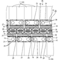
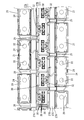
- FIG. 1 is a partial plan view of a battery module to which the battery wiring module of Embodiment 1 is attached.
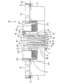
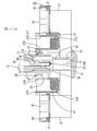
- FIG. 2 is a partial cross-sectional view of the battery module.
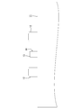
- FIG. 3 is a partial side view of the battery.
- FIG. 4 is a partial plan view of the battery wiring module.
- FIG. 5 is a partial plan view of the resin protector.
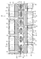
- FIG. 6 is a partial cross-sectional view of the battery module in a disconnected state.
- the battery module M1 is mounted on a vehicle (not shown) such as an electric vehicle or a hybrid vehicle, and is used as a power source for driving the vehicle.
- the battery module M1 has a single battery group 10 in which a plurality of single batteries (not shown) are arranged, and a battery wiring module 20 is attached to the single battery group 10.
- a reference numeral may be assigned to one member for a plurality of identical members, and a reference numeral may be omitted for other members.
- the battery module M ⁇ b> 1 of the present embodiment includes a unit cell group 10 in which a plurality of battery packs 11 formed by connecting four unit cells in series are arranged.
- the unit cell is a thin laminate type unit cell, and a power generation element is accommodated therein.
- Each battery pack 11 has a flat and substantially rectangular parallelepiped shape, and as shown in FIG. 3, positive and negative terminal portions 12 and 12 project from the upper surface thereof.
- the two terminal portions 12 and 12 have the same shape and size.
- Each of the terminal portions 12 and 12 has a hole shape, and is formed with a screw portion (not shown) that can be screwed with a screw thread of a bolt 16 for connecting to a bus bar 21 described later.
- the plurality of battery packs 11 are arranged such that adjacent terminal portions 12 and 12 have different polarities.
- a cylindrical connector portion 13 having an upper opening is provided between the positive and negative terminal portions 12, 12, 12.
- a locking projection 14 is formed on the outer wall of the connector portion 13 to lock a connector 30 (described later) that is a (fitting partner).
- male terminals 15 connected to the respective cells are protruded. That is, four terminals 15 are projected and arranged in one connector portion 13.
- the four terminals 15 arranged in the connector portion 13 are electrically connected to the terminals 37 of the mating connector 30.
- the battery wiring module 20 includes a plurality of metal bus bars 21 connected to the positive terminal portion 12 and the negative terminal portion 12 of the adjacent battery pack 11, a bus bar holding portion 24 that holds the bus bar 21, and a connector 30.
- a synthetic resin resin protector 23 having a connector holding portion 26 to hold is provided.
- the bus bar 21 is formed by pressing a metal plate made of copper, copper alloy, stainless steel (SUS), aluminum or the like into a predetermined shape, and as shown in FIGS. It has a shape.
- the surface of the bus bar 21 may be plated with a metal such as tin or nickel.
- the bus bar 21 is formed with a pair of terminal through holes 22, 22 having a substantially circular shape through which the bolts 16 for connecting to the terminal portions 12, 12 are inserted, through the bus bar 21.
- the terminal through holes 22 and 22 are set slightly larger than the hole diameter of the terminal portions 12 and 12.
- the resin protector 23 is formed by connecting a plurality of connecting units, and has an elongated shape in the direction in which the battery packs 11 are arranged (left and right in FIG. 1), as shown in FIG.
- the resin protector 23 is provided with a plurality of bus bar holding portions 24 that are open upward and have partition walls that can hold the bus bar 21 by partitioning from the outside, and are arranged side by side along the longitudinal direction.
- Each bus bar holding portion 24 is formed with a plurality of pressing pieces 29 for preventing the bus bar 21 from being pulled upward.
- a connector holding portion 26 is provided between the two rows of bus bar holding portions 24 arranged at both ends, and an electric wire receiving groove 27 is provided between the connector holding portion 26 and each bus bar holding portion 24. Yes.
- the electric wire receiving groove 27 is for receiving the electric wire 41 connected to one end of the terminal 37 accommodated in the terminal accommodating portion 35 of the connector 30 held by the connector holding portion 26.
- the two electric wire receiving grooves 27 have a pair of groove wall portions 27A and 27B and a bottom portion 27C connecting them, and a plurality of electric wires 41 can be accommodated therein.
- a wire fixing portion 28 for restricting the protrusion of the electric wire 41 from the wire receiving groove 27 is provided from one groove wall portion 27A to the other groove wall portion 27B.
- the electric wire fixing portion 28 is provided between the adjacent bus bar holding portions 24.
- the retaining pieces 25 are formed at positions for retaining the connectors 30 at two positions from the oblique direction.
- the connector holding part 26 is provided between the two electric wire accommodation grooves 27 (an example of a holding part).
- the connector holding part 26 has a shape along the outer periphery of the connector 30.
- the connector 30 held by the connector holding portion 26 accommodates four terminals 37 as shown in FIG.
- the connector 30 includes a substantially rectangular parallelepiped housing 31 and four terminals 37 accommodated in the housing 31.
- the housing 31 is formed with a locking piece 32 that receives the locking protrusion 14 of the connector portion 13 and is locked to the unit cell.
- the locking piece 32 is formed with a locking hole 32A into which the locking projection 14 is fitted.
- the housing 31 is formed with a retaining protrusion 33 whose retaining is restricted upward by a retaining piece 25 provided on the resin protector 23.
- the housing 31 has a groove 34 for receiving the connector portion 13.
- Four terminal accommodating portions 35 are formed in the housing 31 in parallel.
- a lance 36 that engages with the terminal 37 accommodated in the terminal accommodating portion 35 is formed on the inner peripheral surface of the terminal accommodating portion 35 by projecting into the terminal accommodating portion 35 so as to bend.
- the terminal 37 accommodated in the housing 31 is a so-called female terminal 37, and barrel portions 38 and 39 to which the electric wires 41 are connected are formed at one end (upper end in FIG. 2), and the other end (see FIG. 2 is formed in a box shape, and a connection portion 40 that can be connected to a single cell is formed.
- the barrel portions 38 and 39 are crimped to a wire barrel portion 38 that is crimped to an exposed core wire (not shown) exposed at the end of the electric wire 41 and a portion that is covered with an insulating coating of the electric wire 41. And an insulation barrel portion 39.
- the connecting portion 40 is formed with an elastic contact piece (not shown) so that the unit cell and the terminal 37 of the connector 30 are electrically connected when the elastic contact piece and the terminal 15 of the connector portion 13 come into contact with each other. It has become.
- An engaging portion (not shown) that engages the lance 36 is formed between the connecting portion 40 of the terminal 37 and the barrel portions 38 and 39.
- the terminal 37 accommodated in the connector 30 is a terminal 37 for detecting the state of the unit cell, and specifically, a voltage detection terminal 37 for detecting the voltage of the unit cell.
- the electric wire 41 connected to the terminal 37 is led out of the housing 31 from the inner wall 35A of the terminal accommodating portion 35 (the wall portion arranged on the upper side in FIGS. 2 and 6). It is connected to a control unit (not shown).
- the electric wire 41 is disposed in the electric wire receiving groove 27 on the opposite side of the locking piece 32 of the housing 31.
- the connector 30 is held by the connector holding portion 26 so as to be movable in the vertical direction in FIG. Specifically, the connector 30 electrically connects the connecting portion 40 of the terminal 37 and the unit cell from the non-connection position (for example, the position shown in FIG. 6) that is not connected to the unit cell in the connector holding unit 26. At the same time, it is held so as to be movable to a connection position (position shown in FIG. 2) that is locked to the single cell. In the non-connection position, the terminal 37 of the connector 30 and the terminal 15 of the connector portion 13 are in a non-contact state, and in the connection position, the connection portion 40 of the terminal 37 and the terminal 15 of the connector portion 13 are in a contact state. At the same time, the connector 30 is locked by the connector portion 13.
- the terminal 37 having the electric wire 41 connected to one end is accommodated in the terminal accommodating portion 35 of the connector 30, and the connector 30 is fitted into the connector retaining portion 26 and attached to the connector retaining portion 26.
- the retaining protrusion 33 formed on the housing 31 of the connector 30 contacts the retaining piece 25, and the retaining piece 25 is bent and deformed toward the electric wire receiving groove 27.
- the retaining projection 33 of the housing 31 is disposed below the retaining piece 25 of the connector 30, the retaining piece 25 is elastically restored and the housing 31 is prevented from coming upward.
- the electric wire 41 connected to the connector 30 is accommodated in the electric wire accommodating groove 27 (see FIG. 4).
- the electric wire 41 is accommodated in the electric wire accommodation groove 27 on the side opposite to the locking piece 32 provided in the housing 31 of the connector 30 to which the electric wire 41 is connected.
- a plurality of battery packs 11 are arranged so that adjacent terminal portions 12 and 12 have different polarities, and the battery wiring module 20 in which the bus bar 21 and the connector 30 are arranged is connected to the terminal through hole 22 of the bus bar 21. Is placed on the surface of the battery pack 11 on which the terminal portions 12 and 12 are formed in accordance with the positions of the terminal portions 12 and 12. Then, the connector part 13 of the battery pack 11 is arranged in the connector holding part 26.
- the battery connection bolts 16 are connected to the hole-shaped portions of the terminal portions 12 and 12 inserted into the bus bars 21. After all the bolts 16 are connected, each connector 30 is pushed downward. Before the connector 30 is pushed in, as shown in FIG. 6, the terminal 37 in the housing 31 and the terminal 15 in the connector part 13 are not in contact with each other and are not connected. When the connector 30 is pushed in, the connector portion 13 is received in the groove portion 34 of the housing 31. When the connector 30 is pushed to a position where the locking piece 32 of the housing 31 and the locking protrusion 14 of the connector portion 13 contact each other, the locking piece 32 of the housing 31 is bent and deformed outward.
- each terminal 15 of the connector portion 13 at a corresponding position is received in the connection portion 40 of each terminal 37 in the connector 30.
- the connector 30 is pushed into the locking hole 32A of the housing 31 to the position where the locking protrusion 14 of the connector portion 13 is fitted, the locking piece 32 of the housing 31 is elastically restored, and the housing 31 (connector 30) is connected to the connector 31. Locked to the portion 13 (single cell).
- the connection part 40 (elastic contact piece) of each terminal 37 of the connector 30 and the terminal 15 of the connector part 13 reach a contact state, and the unit cell group 10 and the voltage detection terminal 37 can be electrically connected. (Connection state, see FIG. 2).
- the resin protector 23 is electrically connected to the connection portion 40 of the terminal 37 and the unit cell from the non-connection position where the connector 30 is not connected to the unit cell and is locked to the unit cell. It has a connector holding part 26 movably held at the connection position.
- the terminal 30 having the terminal 37 for detecting the state of the unit cell is held by the connector holding unit 26 of the resin protector 23 and assembled to the unit cell group 10, the terminal 30 is moved to the connection position. 37 and the unit cell can be electrically connected, and the connector 30 is locked to the unit cell.
- the electric wire 41 is connected to one end of the terminal 37 in advance and integrated with the connector 30.
- the resin protector 23 is provided with the retaining piece 25 for retaining the connector 30 in the retaining state, the connector 30 is retained in the retaining state even when in the non-connected position. can do.
- the resin protector 23 is provided with the electric wire fixing portion 28 that prevents the electric wire 41 from jumping out, another member (for example, a bundling member) for fixing the electric wire is unnecessary. Become.
- the present invention is not limited to the embodiments described with reference to the above description and drawings.
- the following embodiments are also included in the technical scope of the present invention.
- the resin protector 23 may be provided with a temporary locking portion that restricts downward movement in a non-connected state.
- the resin protector 23 in which the wire fixing portion 28 is provided in the wire receiving groove 27 is shown in the above embodiment, the wire protector may not be provided, or the wire may be fixed with another member. Also good.
- (3) Although the example which used the voltage detection terminal 37 as the terminal 37 for detecting the state of the electric wire 41 was shown in the said embodiment, you may use the terminal for detecting temperature as a terminal.
Abstract
Cette invention concerne un module de connexion de batterie (20) fixé à un groupe d'éléments individuels (10) formé par montage d'une pluralité d'éléments individuels (11) comprenant des bornes d'électrode positive et négative, ledit module de connexion comprenant : un connecteur (30) comprenant une borne (37) pour détecter l'état d'un élément individuel ; et un élément de protection en résine (23) comprenant une section d'accueil (30) pour accueillir le connecteur (30). Un fil électrique (41) est relié à une section d'extrémité de la borne (37) et une section de connexion (40) raccordable à un élément individuel est formée à l'autre section d'extrémité de la borne (37). Ledit connecteur (30) est accueilli dans la section d'accueil (26) de manière à pouvoir se déplacer d'une position de non contact dans laquelle le connecteur (30) n'est pas connecté à un élément individuel à une position de contact dans laquelle le connecteur (30) connecte la section de connexion (40) de la borne (37) et un élément individuel et il est en contact avec l'élément individuel.
Priority Applications (3)
| Application Number | Priority Date | Filing Date | Title |
|---|---|---|---|
| CN201380038177.4A CN104471744B (zh) | 2012-07-18 | 2013-07-12 | 电池用配线模块 |
| EP13820543.0A EP2860794A4 (fr) | 2012-07-18 | 2013-07-12 | Module de connexion de batterie |
| US14/415,353 US20150194656A1 (en) | 2012-07-18 | 2013-07-12 | Battery wiring module |
Applications Claiming Priority (2)
| Application Number | Priority Date | Filing Date | Title |
|---|---|---|---|
| JP2012-159419 | 2012-07-18 | ||
| JP2012159419A JP5590079B2 (ja) | 2012-07-18 | 2012-07-18 | 電池用配線モジュール |
Publications (1)
| Publication Number | Publication Date |
|---|---|
| WO2014013946A1 true WO2014013946A1 (fr) | 2014-01-23 |
Family
ID=49948775
Family Applications (1)
| Application Number | Title | Priority Date | Filing Date |
|---|---|---|---|
| PCT/JP2013/069122 WO2014013946A1 (fr) | 2012-07-18 | 2013-07-12 | Module de connexion de batterie |
Country Status (5)
| Country | Link |
|---|---|
| US (1) | US20150194656A1 (fr) |
| EP (1) | EP2860794A4 (fr) |
| JP (1) | JP5590079B2 (fr) |
| CN (1) | CN104471744B (fr) |
| WO (1) | WO2014013946A1 (fr) |
Families Citing this family (13)
| Publication number | Priority date | Publication date | Assignee | Title |
|---|---|---|---|---|
| JP6156156B2 (ja) * | 2014-01-14 | 2017-07-05 | 株式会社オートネットワーク技術研究所 | 配線モジュール |
| JP6465354B2 (ja) * | 2015-05-28 | 2019-02-06 | 株式会社オートネットワーク技術研究所 | 蓄電モジュール |
| JP6536314B2 (ja) * | 2015-09-16 | 2019-07-03 | 株式会社オートネットワーク技術研究所 | 配線モジュール |
| JP6680872B2 (ja) * | 2016-04-14 | 2020-04-15 | 株式会社オートネットワーク技術研究所 | 蓄電装置 |
| JP6772816B2 (ja) * | 2016-12-19 | 2020-10-21 | 株式会社豊田自動織機 | コネクタ装置 |
| US10479422B2 (en) * | 2016-12-22 | 2019-11-19 | Polaris Industries Inc. | Side-by-side vehicle |
| JP6299918B1 (ja) * | 2017-08-17 | 2018-03-28 | 株式会社オートネットワーク技術研究所 | 配線モジュール |
| KR101959912B1 (ko) * | 2018-06-12 | 2019-03-19 | 주식회사 경신 | 배터리팩 장착형 와이어링 프로텍터 |
| KR101959911B1 (ko) * | 2018-06-12 | 2019-03-19 | 주식회사 경신 | 배터리팩 장착형 와이어링 프로텍터 |
| KR101959913B1 (ko) * | 2018-06-12 | 2019-03-19 | 주식회사 경신 | 배터리팩 장착형 와이어링 프로텍터 |
| KR102040046B1 (ko) * | 2018-07-30 | 2019-11-27 | (주)에너담 | 방향전환이 가능한 배터리 전극탭 보호장치 |
| CN115315847B (zh) * | 2020-04-01 | 2023-10-03 | Tvs电机股份有限公司 | 电池块 |
| JP2024019925A (ja) * | 2022-08-01 | 2024-02-14 | 住友電装株式会社 | 電池配線モジュール |
Citations (6)
| Publication number | Priority date | Publication date | Assignee | Title |
|---|---|---|---|---|
| JP2009043637A (ja) * | 2007-08-10 | 2009-02-26 | Yazaki Corp | 電源装置 |
| JP2011060675A (ja) * | 2009-09-14 | 2011-03-24 | Yazaki Corp | 電源装置のカバー構造 |
| JP2011091003A (ja) | 2009-10-26 | 2011-05-06 | Autonetworks Technologies Ltd | 電池接続アセンブリ |
| JP2011175928A (ja) * | 2010-02-25 | 2011-09-08 | Autonetworks Technologies Ltd | 電池接続アセンブリ |
| JP2011258413A (ja) * | 2010-06-09 | 2011-12-22 | Auto Network Gijutsu Kenkyusho:Kk | 電池接続アセンブリ |
| JP2013080693A (ja) * | 2011-09-20 | 2013-05-02 | Auto Network Gijutsu Kenkyusho:Kk | 電池用配線モジュール |
Family Cites Families (4)
| Publication number | Priority date | Publication date | Assignee | Title |
|---|---|---|---|---|
| US6981895B2 (en) * | 1999-08-23 | 2006-01-03 | Patrick Potega | Interface apparatus for selectively connecting electrical devices |
| JP5285997B2 (ja) * | 2008-08-27 | 2013-09-11 | 矢崎総業株式会社 | 電源装置 |
| KR101230954B1 (ko) * | 2010-04-08 | 2013-02-07 | 주식회사 엘지화학 | 신규한 구조의 센싱부재를 포함하는 전지모듈 |
| JP5484403B2 (ja) * | 2011-06-08 | 2014-05-07 | 本田技研工業株式会社 | バッテリモジュール |
-
2012
- 2012-07-18 JP JP2012159419A patent/JP5590079B2/ja not_active Expired - Fee Related
-
2013
- 2013-07-12 CN CN201380038177.4A patent/CN104471744B/zh not_active Expired - Fee Related
- 2013-07-12 EP EP13820543.0A patent/EP2860794A4/fr not_active Withdrawn
- 2013-07-12 US US14/415,353 patent/US20150194656A1/en not_active Abandoned
- 2013-07-12 WO PCT/JP2013/069122 patent/WO2014013946A1/fr active Application Filing
Patent Citations (6)
| Publication number | Priority date | Publication date | Assignee | Title |
|---|---|---|---|---|
| JP2009043637A (ja) * | 2007-08-10 | 2009-02-26 | Yazaki Corp | 電源装置 |
| JP2011060675A (ja) * | 2009-09-14 | 2011-03-24 | Yazaki Corp | 電源装置のカバー構造 |
| JP2011091003A (ja) | 2009-10-26 | 2011-05-06 | Autonetworks Technologies Ltd | 電池接続アセンブリ |
| JP2011175928A (ja) * | 2010-02-25 | 2011-09-08 | Autonetworks Technologies Ltd | 電池接続アセンブリ |
| JP2011258413A (ja) * | 2010-06-09 | 2011-12-22 | Auto Network Gijutsu Kenkyusho:Kk | 電池接続アセンブリ |
| JP2013080693A (ja) * | 2011-09-20 | 2013-05-02 | Auto Network Gijutsu Kenkyusho:Kk | 電池用配線モジュール |
Non-Patent Citations (1)
| Title |
|---|
| See also references of EP2860794A4 |
Also Published As
| Publication number | Publication date |
|---|---|
| CN104471744A (zh) | 2015-03-25 |
| US20150194656A1 (en) | 2015-07-09 |
| JP2014022175A (ja) | 2014-02-03 |
| JP5590079B2 (ja) | 2014-09-17 |
| EP2860794A4 (fr) | 2015-06-17 |
| CN104471744B (zh) | 2017-05-24 |
| EP2860794A1 (fr) | 2015-04-15 |
Similar Documents
| Publication | Publication Date | Title |
|---|---|---|
| WO2014013946A1 (fr) | Module de connexion de batterie | |
| US9543711B2 (en) | Wiring module | |
| JP6099211B2 (ja) | バッテリコネクタシステム | |
| US10008709B2 (en) | Bus bar module, battery monitoring module, and battery module | |
| US9397327B2 (en) | Battery connecting assembly | |
| US9526187B2 (en) | Wiring module | |
| WO2016098605A1 (fr) | Module de détection | |
| WO2013069526A1 (fr) | Module de câblage de batterie | |
| EP2953181B1 (fr) | Module de câblage | |
| JP2009043637A (ja) | 電源装置 | |
| CN106935780B (zh) | 电池模块和电池组 | |
| JP2013016381A (ja) | 電池配線モジュール | |
| JP2011258413A (ja) | 電池接続アセンブリ | |
| WO2015156188A1 (fr) | Module de câblage | |
| JP2015056910A (ja) | 配線モジュール | |
| JP5974918B2 (ja) | 配線モジュール | |
| JP7174482B2 (ja) | 電池モジュール | |
| JP5751676B2 (ja) | 電池用配線モジュール | |
| JP6156156B2 (ja) | 配線モジュール | |
| JP6577303B2 (ja) | ソケット | |
| KR101800398B1 (ko) | 전압 센싱 어셈블리 및 이를 포함하는 전지 모듈 | |
| JP2013171726A (ja) | 電池モジュール | |
| WO2014049654A1 (fr) | Connecteur, et bloc-batterie |
Legal Events
| Date | Code | Title | Description |
|---|---|---|---|
| 121 | Ep: the epo has been informed by wipo that ep was designated in this application |
Ref document number: 13820543 Country of ref document: EP Kind code of ref document: A1 |
|
| WWE | Wipo information: entry into national phase |
Ref document number: 2013820543 Country of ref document: EP |
|
| WWE | Wipo information: entry into national phase |
Ref document number: 14415353 Country of ref document: US |
|
| NENP | Non-entry into the national phase |
Ref country code: DE |