WO2014013946A1 - Battery wiring module - Google Patents
Battery wiring module Download PDFInfo
- Publication number
- WO2014013946A1 WO2014013946A1 PCT/JP2013/069122 JP2013069122W WO2014013946A1 WO 2014013946 A1 WO2014013946 A1 WO 2014013946A1 JP 2013069122 W JP2013069122 W JP 2013069122W WO 2014013946 A1 WO2014013946 A1 WO 2014013946A1
- Authority
- WO
- WIPO (PCT)
- Prior art keywords
- connector
- terminal
- unit cell
- electric wire
- holding
- Prior art date
Links
Images
Classifications
-
- H—ELECTRICITY
- H01—ELECTRIC ELEMENTS
- H01M—PROCESSES OR MEANS, e.g. BATTERIES, FOR THE DIRECT CONVERSION OF CHEMICAL ENERGY INTO ELECTRICAL ENERGY
- H01M10/00—Secondary cells; Manufacture thereof
- H01M10/42—Methods or arrangements for servicing or maintenance of secondary cells or secondary half-cells
- H01M10/48—Accumulators combined with arrangements for measuring, testing or indicating the condition of cells, e.g. the level or density of the electrolyte
- H01M10/482—Accumulators combined with arrangements for measuring, testing or indicating the condition of cells, e.g. the level or density of the electrolyte for several batteries or cells simultaneously or sequentially
-
- H—ELECTRICITY
- H01—ELECTRIC ELEMENTS
- H01M—PROCESSES OR MEANS, e.g. BATTERIES, FOR THE DIRECT CONVERSION OF CHEMICAL ENERGY INTO ELECTRICAL ENERGY
- H01M50/00—Constructional details or processes of manufacture of the non-active parts of electrochemical cells other than fuel cells, e.g. hybrid cells
- H01M50/20—Mountings; Secondary casings or frames; Racks, modules or packs; Suspension devices; Shock absorbers; Transport or carrying devices; Holders
- H01M50/298—Mountings; Secondary casings or frames; Racks, modules or packs; Suspension devices; Shock absorbers; Transport or carrying devices; Holders characterised by the wiring of battery packs
-
- H—ELECTRICITY
- H01—ELECTRIC ELEMENTS
- H01M—PROCESSES OR MEANS, e.g. BATTERIES, FOR THE DIRECT CONVERSION OF CHEMICAL ENERGY INTO ELECTRICAL ENERGY
- H01M50/00—Constructional details or processes of manufacture of the non-active parts of electrochemical cells other than fuel cells, e.g. hybrid cells
- H01M50/50—Current conducting connections for cells or batteries
- H01M50/502—Interconnectors for connecting terminals of adjacent batteries; Interconnectors for connecting cells outside a battery casing
- H01M50/505—Interconnectors for connecting terminals of adjacent batteries; Interconnectors for connecting cells outside a battery casing comprising a single busbar
-
- H—ELECTRICITY
- H01—ELECTRIC ELEMENTS
- H01M—PROCESSES OR MEANS, e.g. BATTERIES, FOR THE DIRECT CONVERSION OF CHEMICAL ENERGY INTO ELECTRICAL ENERGY
- H01M50/00—Constructional details or processes of manufacture of the non-active parts of electrochemical cells other than fuel cells, e.g. hybrid cells
- H01M50/50—Current conducting connections for cells or batteries
- H01M50/502—Interconnectors for connecting terminals of adjacent batteries; Interconnectors for connecting cells outside a battery casing
- H01M50/514—Methods for interconnecting adjacent batteries or cells
- H01M50/517—Methods for interconnecting adjacent batteries or cells by fixing means, e.g. screws, rivets or bolts
-
- H—ELECTRICITY
- H01—ELECTRIC ELEMENTS
- H01M—PROCESSES OR MEANS, e.g. BATTERIES, FOR THE DIRECT CONVERSION OF CHEMICAL ENERGY INTO ELECTRICAL ENERGY
- H01M2220/00—Batteries for particular applications
- H01M2220/20—Batteries in motive systems, e.g. vehicle, ship, plane
-
- H—ELECTRICITY
- H01—ELECTRIC ELEMENTS
- H01M—PROCESSES OR MEANS, e.g. BATTERIES, FOR THE DIRECT CONVERSION OF CHEMICAL ENERGY INTO ELECTRICAL ENERGY
- H01M50/00—Constructional details or processes of manufacture of the non-active parts of electrochemical cells other than fuel cells, e.g. hybrid cells
- H01M50/20—Mountings; Secondary casings or frames; Racks, modules or packs; Suspension devices; Shock absorbers; Transport or carrying devices; Holders
- H01M50/204—Racks, modules or packs for multiple batteries or multiple cells
- H01M50/207—Racks, modules or packs for multiple batteries or multiple cells characterised by their shape
- H01M50/209—Racks, modules or packs for multiple batteries or multiple cells characterised by their shape adapted for prismatic or rectangular cells
-
- H—ELECTRICITY
- H01—ELECTRIC ELEMENTS
- H01M—PROCESSES OR MEANS, e.g. BATTERIES, FOR THE DIRECT CONVERSION OF CHEMICAL ENERGY INTO ELECTRICAL ENERGY
- H01M50/00—Constructional details or processes of manufacture of the non-active parts of electrochemical cells other than fuel cells, e.g. hybrid cells
- H01M50/20—Mountings; Secondary casings or frames; Racks, modules or packs; Suspension devices; Shock absorbers; Transport or carrying devices; Holders
- H01M50/249—Mountings; Secondary casings or frames; Racks, modules or packs; Suspension devices; Shock absorbers; Transport or carrying devices; Holders specially adapted for aircraft or vehicles, e.g. cars or trains
-
- H—ELECTRICITY
- H01—ELECTRIC ELEMENTS
- H01M—PROCESSES OR MEANS, e.g. BATTERIES, FOR THE DIRECT CONVERSION OF CHEMICAL ENERGY INTO ELECTRICAL ENERGY
- H01M50/00—Constructional details or processes of manufacture of the non-active parts of electrochemical cells other than fuel cells, e.g. hybrid cells
- H01M50/50—Current conducting connections for cells or batteries
- H01M50/502—Interconnectors for connecting terminals of adjacent batteries; Interconnectors for connecting cells outside a battery casing
- H01M50/509—Interconnectors for connecting terminals of adjacent batteries; Interconnectors for connecting cells outside a battery casing characterised by the type of connection, e.g. mixed connections
- H01M50/51—Connection only in series
-
- Y—GENERAL TAGGING OF NEW TECHNOLOGICAL DEVELOPMENTS; GENERAL TAGGING OF CROSS-SECTIONAL TECHNOLOGIES SPANNING OVER SEVERAL SECTIONS OF THE IPC; TECHNICAL SUBJECTS COVERED BY FORMER USPC CROSS-REFERENCE ART COLLECTIONS [XRACs] AND DIGESTS
- Y02—TECHNOLOGIES OR APPLICATIONS FOR MITIGATION OR ADAPTATION AGAINST CLIMATE CHANGE
- Y02E—REDUCTION OF GREENHOUSE GAS [GHG] EMISSIONS, RELATED TO ENERGY GENERATION, TRANSMISSION OR DISTRIBUTION
- Y02E60/00—Enabling technologies; Technologies with a potential or indirect contribution to GHG emissions mitigation
- Y02E60/10—Energy storage using batteries
Definitions
- the present invention relates to a battery wiring module.
- a battery module mounted on, for example, an electric vehicle or a hybrid vehicle is generally configured by connecting a large number of single cells in series via a bus bar.
- Such a battery module includes, for example, a terminal for detecting the state (voltage, temperature, etc.) of the unit cell group and an electric wire that connects the terminal and a controller such as an ECU (see, for example, Patent Document 1). .
- Patent Document 1 Japanese Patent Application Laid-Open No. 2011-91003
- a voltage detection terminal to which a voltage detection line (electric wire) is crimped is bolted to an electrode together with a bus bar that connects the cells, whereby the voltage detection terminal is a single cell. It can be electrically connected to a controller such as an ECU for controlling the group and the battery.
- the present invention has been completed based on the above-described circumstances, and an object thereof is to simplify the connection work of terminals for detecting the state of a unit cell.
- the present invention provides a battery wiring module attached to a unit cell group in which a plurality of unit cells having positive and negative electrode terminals are arranged, for detecting the state of the unit cell.
- a connector having a terminal and a resin protector having a holding portion for holding the connector, wherein an electric wire is connected to one end of the terminal, and the cell can be connected to the other end of the terminal
- the connector electrically connects the terminal connection portion and the unit cell from a non-connection position where the connector is not connected to the unit cell. It is the battery wiring module movably held at the connection position locked against.
- the resin protector can move the connector from a non-connection position not connected to the unit cell to a connection position where the connection part of the terminal and the unit cell are electrically connected and locked to the unit cell. And a holding portion for holding. Therefore, when a connector having a terminal for detecting the state of the unit cell is held by the holding part of the resin protector and assembled to the unit cell group, and then moved to the connection position, the terminal and the unit cell are electrically connected. And the connector is locked to the unit cell. Moreover, the electric wire is connected to one end of the terminal in advance and integrated with the connector. As a result, according to the present invention, it is possible to simplify the connection operation of the terminals for detecting the state of the unit cells.
- the present invention preferably has the following configuration. It is preferable that the resin protector be provided with a retaining portion that retains the connector in the retaining state because the connector can be retained in the retaining state even when the connector is in the non-connection position.
- the resin protector be provided with an electric wire fixing portion that prevents the electric wire from popping out, since another member (for example, a bundling member) for fixing the electric wire becomes unnecessary.
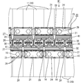
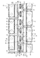
- FIG. 1 is a partial plan view of a battery module to which the battery wiring module of Embodiment 1 is attached.
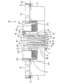
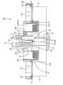
- FIG. 2 is a partial cross-sectional view of the battery module.
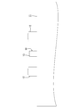
- FIG. 3 is a partial side view of the battery.
- FIG. 4 is a partial plan view of the battery wiring module.
- FIG. 5 is a partial plan view of the resin protector.
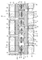
- FIG. 6 is a partial cross-sectional view of the battery module in a disconnected state.
- the battery module M1 is mounted on a vehicle (not shown) such as an electric vehicle or a hybrid vehicle, and is used as a power source for driving the vehicle.
- the battery module M1 has a single battery group 10 in which a plurality of single batteries (not shown) are arranged, and a battery wiring module 20 is attached to the single battery group 10.
- a reference numeral may be assigned to one member for a plurality of identical members, and a reference numeral may be omitted for other members.
- the battery module M ⁇ b> 1 of the present embodiment includes a unit cell group 10 in which a plurality of battery packs 11 formed by connecting four unit cells in series are arranged.
- the unit cell is a thin laminate type unit cell, and a power generation element is accommodated therein.
- Each battery pack 11 has a flat and substantially rectangular parallelepiped shape, and as shown in FIG. 3, positive and negative terminal portions 12 and 12 project from the upper surface thereof.
- the two terminal portions 12 and 12 have the same shape and size.
- Each of the terminal portions 12 and 12 has a hole shape, and is formed with a screw portion (not shown) that can be screwed with a screw thread of a bolt 16 for connecting to a bus bar 21 described later.
- the plurality of battery packs 11 are arranged such that adjacent terminal portions 12 and 12 have different polarities.
- a cylindrical connector portion 13 having an upper opening is provided between the positive and negative terminal portions 12, 12, 12.
- a locking projection 14 is formed on the outer wall of the connector portion 13 to lock a connector 30 (described later) that is a (fitting partner).
- male terminals 15 connected to the respective cells are protruded. That is, four terminals 15 are projected and arranged in one connector portion 13.
- the four terminals 15 arranged in the connector portion 13 are electrically connected to the terminals 37 of the mating connector 30.
- the battery wiring module 20 includes a plurality of metal bus bars 21 connected to the positive terminal portion 12 and the negative terminal portion 12 of the adjacent battery pack 11, a bus bar holding portion 24 that holds the bus bar 21, and a connector 30.
- a synthetic resin resin protector 23 having a connector holding portion 26 to hold is provided.
- the bus bar 21 is formed by pressing a metal plate made of copper, copper alloy, stainless steel (SUS), aluminum or the like into a predetermined shape, and as shown in FIGS. It has a shape.
- the surface of the bus bar 21 may be plated with a metal such as tin or nickel.
- the bus bar 21 is formed with a pair of terminal through holes 22, 22 having a substantially circular shape through which the bolts 16 for connecting to the terminal portions 12, 12 are inserted, through the bus bar 21.
- the terminal through holes 22 and 22 are set slightly larger than the hole diameter of the terminal portions 12 and 12.
- the resin protector 23 is formed by connecting a plurality of connecting units, and has an elongated shape in the direction in which the battery packs 11 are arranged (left and right in FIG. 1), as shown in FIG.
- the resin protector 23 is provided with a plurality of bus bar holding portions 24 that are open upward and have partition walls that can hold the bus bar 21 by partitioning from the outside, and are arranged side by side along the longitudinal direction.
- Each bus bar holding portion 24 is formed with a plurality of pressing pieces 29 for preventing the bus bar 21 from being pulled upward.
- a connector holding portion 26 is provided between the two rows of bus bar holding portions 24 arranged at both ends, and an electric wire receiving groove 27 is provided between the connector holding portion 26 and each bus bar holding portion 24. Yes.
- the electric wire receiving groove 27 is for receiving the electric wire 41 connected to one end of the terminal 37 accommodated in the terminal accommodating portion 35 of the connector 30 held by the connector holding portion 26.
- the two electric wire receiving grooves 27 have a pair of groove wall portions 27A and 27B and a bottom portion 27C connecting them, and a plurality of electric wires 41 can be accommodated therein.
- a wire fixing portion 28 for restricting the protrusion of the electric wire 41 from the wire receiving groove 27 is provided from one groove wall portion 27A to the other groove wall portion 27B.
- the electric wire fixing portion 28 is provided between the adjacent bus bar holding portions 24.
- the retaining pieces 25 are formed at positions for retaining the connectors 30 at two positions from the oblique direction.
- the connector holding part 26 is provided between the two electric wire accommodation grooves 27 (an example of a holding part).
- the connector holding part 26 has a shape along the outer periphery of the connector 30.
- the connector 30 held by the connector holding portion 26 accommodates four terminals 37 as shown in FIG.
- the connector 30 includes a substantially rectangular parallelepiped housing 31 and four terminals 37 accommodated in the housing 31.
- the housing 31 is formed with a locking piece 32 that receives the locking protrusion 14 of the connector portion 13 and is locked to the unit cell.
- the locking piece 32 is formed with a locking hole 32A into which the locking projection 14 is fitted.
- the housing 31 is formed with a retaining protrusion 33 whose retaining is restricted upward by a retaining piece 25 provided on the resin protector 23.
- the housing 31 has a groove 34 for receiving the connector portion 13.
- Four terminal accommodating portions 35 are formed in the housing 31 in parallel.
- a lance 36 that engages with the terminal 37 accommodated in the terminal accommodating portion 35 is formed on the inner peripheral surface of the terminal accommodating portion 35 by projecting into the terminal accommodating portion 35 so as to bend.
- the terminal 37 accommodated in the housing 31 is a so-called female terminal 37, and barrel portions 38 and 39 to which the electric wires 41 are connected are formed at one end (upper end in FIG. 2), and the other end (see FIG. 2 is formed in a box shape, and a connection portion 40 that can be connected to a single cell is formed.
- the barrel portions 38 and 39 are crimped to a wire barrel portion 38 that is crimped to an exposed core wire (not shown) exposed at the end of the electric wire 41 and a portion that is covered with an insulating coating of the electric wire 41. And an insulation barrel portion 39.
- the connecting portion 40 is formed with an elastic contact piece (not shown) so that the unit cell and the terminal 37 of the connector 30 are electrically connected when the elastic contact piece and the terminal 15 of the connector portion 13 come into contact with each other. It has become.
- An engaging portion (not shown) that engages the lance 36 is formed between the connecting portion 40 of the terminal 37 and the barrel portions 38 and 39.
- the terminal 37 accommodated in the connector 30 is a terminal 37 for detecting the state of the unit cell, and specifically, a voltage detection terminal 37 for detecting the voltage of the unit cell.
- the electric wire 41 connected to the terminal 37 is led out of the housing 31 from the inner wall 35A of the terminal accommodating portion 35 (the wall portion arranged on the upper side in FIGS. 2 and 6). It is connected to a control unit (not shown).
- the electric wire 41 is disposed in the electric wire receiving groove 27 on the opposite side of the locking piece 32 of the housing 31.
- the connector 30 is held by the connector holding portion 26 so as to be movable in the vertical direction in FIG. Specifically, the connector 30 electrically connects the connecting portion 40 of the terminal 37 and the unit cell from the non-connection position (for example, the position shown in FIG. 6) that is not connected to the unit cell in the connector holding unit 26. At the same time, it is held so as to be movable to a connection position (position shown in FIG. 2) that is locked to the single cell. In the non-connection position, the terminal 37 of the connector 30 and the terminal 15 of the connector portion 13 are in a non-contact state, and in the connection position, the connection portion 40 of the terminal 37 and the terminal 15 of the connector portion 13 are in a contact state. At the same time, the connector 30 is locked by the connector portion 13.
- the terminal 37 having the electric wire 41 connected to one end is accommodated in the terminal accommodating portion 35 of the connector 30, and the connector 30 is fitted into the connector retaining portion 26 and attached to the connector retaining portion 26.
- the retaining protrusion 33 formed on the housing 31 of the connector 30 contacts the retaining piece 25, and the retaining piece 25 is bent and deformed toward the electric wire receiving groove 27.
- the retaining projection 33 of the housing 31 is disposed below the retaining piece 25 of the connector 30, the retaining piece 25 is elastically restored and the housing 31 is prevented from coming upward.
- the electric wire 41 connected to the connector 30 is accommodated in the electric wire accommodating groove 27 (see FIG. 4).
- the electric wire 41 is accommodated in the electric wire accommodation groove 27 on the side opposite to the locking piece 32 provided in the housing 31 of the connector 30 to which the electric wire 41 is connected.
- a plurality of battery packs 11 are arranged so that adjacent terminal portions 12 and 12 have different polarities, and the battery wiring module 20 in which the bus bar 21 and the connector 30 are arranged is connected to the terminal through hole 22 of the bus bar 21. Is placed on the surface of the battery pack 11 on which the terminal portions 12 and 12 are formed in accordance with the positions of the terminal portions 12 and 12. Then, the connector part 13 of the battery pack 11 is arranged in the connector holding part 26.
- the battery connection bolts 16 are connected to the hole-shaped portions of the terminal portions 12 and 12 inserted into the bus bars 21. After all the bolts 16 are connected, each connector 30 is pushed downward. Before the connector 30 is pushed in, as shown in FIG. 6, the terminal 37 in the housing 31 and the terminal 15 in the connector part 13 are not in contact with each other and are not connected. When the connector 30 is pushed in, the connector portion 13 is received in the groove portion 34 of the housing 31. When the connector 30 is pushed to a position where the locking piece 32 of the housing 31 and the locking protrusion 14 of the connector portion 13 contact each other, the locking piece 32 of the housing 31 is bent and deformed outward.
- each terminal 15 of the connector portion 13 at a corresponding position is received in the connection portion 40 of each terminal 37 in the connector 30.
- the connector 30 is pushed into the locking hole 32A of the housing 31 to the position where the locking protrusion 14 of the connector portion 13 is fitted, the locking piece 32 of the housing 31 is elastically restored, and the housing 31 (connector 30) is connected to the connector 31. Locked to the portion 13 (single cell).
- the connection part 40 (elastic contact piece) of each terminal 37 of the connector 30 and the terminal 15 of the connector part 13 reach a contact state, and the unit cell group 10 and the voltage detection terminal 37 can be electrically connected. (Connection state, see FIG. 2).
- the resin protector 23 is electrically connected to the connection portion 40 of the terminal 37 and the unit cell from the non-connection position where the connector 30 is not connected to the unit cell and is locked to the unit cell. It has a connector holding part 26 movably held at the connection position.
- the terminal 30 having the terminal 37 for detecting the state of the unit cell is held by the connector holding unit 26 of the resin protector 23 and assembled to the unit cell group 10, the terminal 30 is moved to the connection position. 37 and the unit cell can be electrically connected, and the connector 30 is locked to the unit cell.
- the electric wire 41 is connected to one end of the terminal 37 in advance and integrated with the connector 30.
- the resin protector 23 is provided with the retaining piece 25 for retaining the connector 30 in the retaining state, the connector 30 is retained in the retaining state even when in the non-connected position. can do.
- the resin protector 23 is provided with the electric wire fixing portion 28 that prevents the electric wire 41 from jumping out, another member (for example, a bundling member) for fixing the electric wire is unnecessary. Become.
- the present invention is not limited to the embodiments described with reference to the above description and drawings.
- the following embodiments are also included in the technical scope of the present invention.
- the resin protector 23 may be provided with a temporary locking portion that restricts downward movement in a non-connected state.
- the resin protector 23 in which the wire fixing portion 28 is provided in the wire receiving groove 27 is shown in the above embodiment, the wire protector may not be provided, or the wire may be fixed with another member. Also good.
- (3) Although the example which used the voltage detection terminal 37 as the terminal 37 for detecting the state of the electric wire 41 was shown in the said embodiment, you may use the terminal for detecting temperature as a terminal.
Landscapes
- Chemical & Material Sciences (AREA)
- Chemical Kinetics & Catalysis (AREA)
- Electrochemistry (AREA)
- General Chemical & Material Sciences (AREA)
- Engineering & Computer Science (AREA)
- Manufacturing & Machinery (AREA)
- Connection Of Batteries Or Terminals (AREA)
- Battery Mounting, Suspending (AREA)
- Connector Housings Or Holding Contact Members (AREA)
- Secondary Cells (AREA)
Abstract
A battery wiring module (20) that is attached to a single cell group (10) obtained by arraying a plurality of single cells comprising positive and negative electrode terminals is provided with: a connector (30) comprising a terminal (37) for detecting the state of a single cell; and a resin protector (23) comprising a holding section (27) for holding the connector (30). An electrical wire (41) is connected to one end section of the terminal (37), and a connecting section (40) that is connectable to a single cell is formed on the other end section of the terminal (37). The connector (30) is held at the holding section (26) so as to be movable from a non-contact position in which the connector (30) is not connected to a single cell to a contact position in which the connector (30) connects the connecting section (40) of the terminal (37) and a single cell and is engaged with the single cell.
Description
本発明は、電池用配線モジュールに関する。
The present invention relates to a battery wiring module.
例えば電気自動車やハイブリッド車両に搭載される電池モジュールは、一般に、多数の単電池を、バスバーを介して直列接続することにより構成されている。
For example, a battery module mounted on, for example, an electric vehicle or a hybrid vehicle is generally configured by connecting a large number of single cells in series via a bus bar.
このような電池モジュールは、例えば、単電池群の状態(電圧や温度等)を検出するための端子や、当該端子とECU等のコントローラとを接続する電線を備える(例えば特許文献1を参照)。
Such a battery module includes, for example, a terminal for detecting the state (voltage, temperature, etc.) of the unit cell group and an electric wire that connects the terminal and a controller such as an ECU (see, for example, Patent Document 1). .
特許文献1:特開2011-91003号公報
Patent Document 1: Japanese Patent Application Laid-Open No. 2011-91003
上記特許文献1においては、電圧検知線(電線)が圧着された電圧検知端子(端子)が、単電池間を接続するバスバーとともに電極にボルト締めされており、これにより、電圧検知端子が単電池群およびバッテリを制御するECU等のコントローラと電気的に接続可能とされる。
In Patent Document 1, a voltage detection terminal (terminal) to which a voltage detection line (electric wire) is crimped is bolted to an electrode together with a bus bar that connects the cells, whereby the voltage detection terminal is a single cell. It can be electrically connected to a controller such as an ECU for controlling the group and the battery.
ところで、端子とバッテリを制御するコントローラ等の機器とを接続する方法として、ボルト締め以外に、コネクタを用いる方法がある。しかしながら、多数の単電池を備える電池モジュールにおいてコネクタを用いる場合、コネクタに接続されている電線の長さでコネクタ位置を決定しながら、同一あるいは類似の多数のコネクタを組み付ける必要があるため、誤って組み付ける可能性が高かった。また、コネクタを組み付けた後に電線を固定する作業が必要なので作業工数が多いという問題があった。
By the way, as a method for connecting the terminal and a device such as a controller for controlling the battery, there is a method using a connector in addition to bolting. However, when using a connector in a battery module having a large number of single cells, it is necessary to assemble a large number of identical or similar connectors while determining the connector position based on the length of the wire connected to the connector. The possibility of assembly was high. In addition, since it is necessary to fix the electric wire after the connector is assembled, there is a problem that the number of work steps is large.
本発明は上記のような事情に基づいて完成されたものであって、単電池の状態を検出するための端子の接続作業を簡易なものとすることを目的とする。
The present invention has been completed based on the above-described circumstances, and an object thereof is to simplify the connection work of terminals for detecting the state of a unit cell.
上記課題を解決するものとして本発明は、正極及び負極の電極端子を有する単電池を複数個並べてなる単電池群に取り付けられる電池用配線モジュールであって、前記単電池の状態を検出するための端子を有するコネクタと、前記コネクタを保持する保持部を有する樹脂プロテクタと、を備え、前記端子の一端部には電線が接続されるとともに、前記端子の他端部には前記単電池と接続可能な接続部が形成され、前記コネクタは、前記保持部において、前記単電池に接続されていない非接続位置から、前記端子の接続部と前記単電池とを電気的に接続するとともに前記単電池に対して係止される接続位置に移動可能に保持されている電池用配線モジュールである。
In order to solve the above problems, the present invention provides a battery wiring module attached to a unit cell group in which a plurality of unit cells having positive and negative electrode terminals are arranged, for detecting the state of the unit cell. A connector having a terminal and a resin protector having a holding portion for holding the connector, wherein an electric wire is connected to one end of the terminal, and the cell can be connected to the other end of the terminal In the holding portion, the connector electrically connects the terminal connection portion and the unit cell from a non-connection position where the connector is not connected to the unit cell. It is the battery wiring module movably held at the connection position locked against.
本発明において、樹脂プロテクタは、コネクタを、単電池に接続されていない非接続位置から、端子の接続部と単電池とを電気的に接続するとともに単電池に係止される接続位置に移動可能に保持する保持部を有する。したがって、単電池の状態を検出するための端子を有するコネクタを、樹脂プロテクタの保持部に保持させて、単電池群に組みつけた後に、接続位置に移動させると、端子と単電池とを電気的に接続させることができるとともに、コネクタが単電池に係止される。また、電線は予め端子の一端部に接続されコネクタと一体化されている。
その結果、本発明によれば、単電池の状態を検出するための端子の接続作業を簡易なものとすることができる。 In the present invention, the resin protector can move the connector from a non-connection position not connected to the unit cell to a connection position where the connection part of the terminal and the unit cell are electrically connected and locked to the unit cell. And a holding portion for holding. Therefore, when a connector having a terminal for detecting the state of the unit cell is held by the holding part of the resin protector and assembled to the unit cell group, and then moved to the connection position, the terminal and the unit cell are electrically connected. And the connector is locked to the unit cell. Moreover, the electric wire is connected to one end of the terminal in advance and integrated with the connector.
As a result, according to the present invention, it is possible to simplify the connection operation of the terminals for detecting the state of the unit cells.
本発明は以下の構成とするのが好ましい。
樹脂プロテクタに、コネクタを抜け止め状態に保持する抜け止め部が設けられていると、非接続位置にあるときにもコネクタを抜け止め状態に保持することができるので好ましい。 The present invention preferably has the following configuration.
It is preferable that the resin protector be provided with a retaining portion that retains the connector in the retaining state because the connector can be retained in the retaining state even when the connector is in the non-connection position.
樹脂プロテクタに、電線の飛び出しを防止する電線固定部が設けられていると、電線を固定するための別の部材(例えば結束部材等)が不要となるので好ましい。
It is preferable that the resin protector be provided with an electric wire fixing portion that prevents the electric wire from popping out, since another member (for example, a bundling member) for fixing the electric wire becomes unnecessary.
本発明によれば、単電池の状態を検出するための端子の接続作業を簡易なものとすることができる。
According to the present invention, it is possible to simplify the connection work of the terminals for detecting the state of the unit cell.
<実施形態1>
本発明の実施形態1を図1ないし図6によって説明する。本実施形態に係る電池モジュールM1は、電気自動車又はハイブリッド自動車等の車両(図示せず)に搭載されて、車両を駆動するための電源として使用される。 <Embodiment 1>
A first embodiment of the present invention will be described with reference to FIGS. The battery module M1 according to this embodiment is mounted on a vehicle (not shown) such as an electric vehicle or a hybrid vehicle, and is used as a power source for driving the vehicle.
電池モジュールM1は、複数の単電池(図示せず)を並べてなる単電池群10を有し、単電池群10には電池用配線モジュール20が取り付けられている。以下の説明において、複数の同一部材については、一の部材に符号を付し、他の部材については符号を省略することがある。
The battery module M1 has a single battery group 10 in which a plurality of single batteries (not shown) are arranged, and a battery wiring module 20 is attached to the single battery group 10. In the following description, a reference numeral may be assigned to one member for a plurality of identical members, and a reference numeral may be omitted for other members.
(単電池群10)
本実施形態の電池モジュールM1は、図1に示すように、4個の単電池を直列接続してなる電池パック11を複数並べてなる単電池群10を有する。本実施形態において、単電池は厚みの薄いラミネート型の単電池であり、その内部には発電要素が収容されている。 (Single cell group 10)
As shown in FIG. 1, the battery module M <b> 1 of the present embodiment includes aunit cell group 10 in which a plurality of battery packs 11 formed by connecting four unit cells in series are arranged. In the present embodiment, the unit cell is a thin laminate type unit cell, and a power generation element is accommodated therein.
本実施形態の電池モジュールM1は、図1に示すように、4個の単電池を直列接続してなる電池パック11を複数並べてなる単電池群10を有する。本実施形態において、単電池は厚みの薄いラミネート型の単電池であり、その内部には発電要素が収容されている。 (Single cell group 10)
As shown in FIG. 1, the battery module M <b> 1 of the present embodiment includes a
各電池パック11は扁平な略直方体形状をなし、図3に示すように、その上面からは正極および負極の端子部12,12が突出形成されている。2つの端子部12,12は同形同大である。各端子部12,12は、孔状をなしており、後述するバスバー21と接続するためのボルト16のねじ山と螺合可能なねじ部(図示せず)が形成されている。複数の電池パック11は、隣り合う端子部12,12が異なる極性となるように配置されている。
Each battery pack 11 has a flat and substantially rectangular parallelepiped shape, and as shown in FIG. 3, positive and negative terminal portions 12 and 12 project from the upper surface thereof. The two terminal portions 12 and 12 have the same shape and size. Each of the terminal portions 12 and 12 has a hole shape, and is formed with a screw portion (not shown) that can be screwed with a screw thread of a bolt 16 for connecting to a bus bar 21 described later. The plurality of battery packs 11 are arranged such that adjacent terminal portions 12 and 12 have different polarities.
正極および負極の端子部12,12の間には、図2に示すように、上方が開口した筒状のコネクタ部13が設けられている。コネクタ部13の外壁には、図3および図6に示すように、(嵌合相手)となるコネクタ30(後述する)を係止する係止突部14が形成されている。
Between the positive and negative terminal portions 12, 12, a cylindrical connector portion 13 having an upper opening is provided as shown in FIG. As shown in FIGS. 3 and 6, a locking projection 14 is formed on the outer wall of the connector portion 13 to lock a connector 30 (described later) that is a (fitting partner).
コネクタ部13内には各単電池と接続されている雄型の端子15が突出して配されている。つまり1つのコネクタ部13内には4つの端子15が突出して配されていることになる。コネクタ部13内に配置されている4つの端子15は、相手方のコネクタ30の端子37と電気的に接続されるようになっている。
In the connector part 13, male terminals 15 connected to the respective cells are protruded. That is, four terminals 15 are projected and arranged in one connector portion 13. The four terminals 15 arranged in the connector portion 13 are electrically connected to the terminals 37 of the mating connector 30.
(電池用配線モジュール20)
電池用配線モジュール20は、隣り合う電池パック11の正極の端子部12および負極の端子部12に接続される金属製の複数のバスバー21と、バスバー21を保持するバスバー保持部24およびコネクタ30を保持するコネクタ保持部26を有する合成樹脂製の樹脂プロテクタ23を備える。 (Battery wiring module 20)
Thebattery wiring module 20 includes a plurality of metal bus bars 21 connected to the positive terminal portion 12 and the negative terminal portion 12 of the adjacent battery pack 11, a bus bar holding portion 24 that holds the bus bar 21, and a connector 30. A synthetic resin resin protector 23 having a connector holding portion 26 to hold is provided.
電池用配線モジュール20は、隣り合う電池パック11の正極の端子部12および負極の端子部12に接続される金属製の複数のバスバー21と、バスバー21を保持するバスバー保持部24およびコネクタ30を保持するコネクタ保持部26を有する合成樹脂製の樹脂プロテクタ23を備える。 (Battery wiring module 20)
The
(バスバー21)
バスバー21は、銅、銅合金、ステンレス鋼(SUS)、アルミニウム等からなる金属製の板材を所定の形状にプレス加工することにより形成され、図4および図5に示すように、全体として略長方形状をなしている。バスバー21の表面には、スズ、ニッケル等の金属がメッキされていてもよい。バスバー21には、端子部12,12と接続するためのボルト16が挿通される略円形状をなす一対の端子貫通孔22,22が、バスバー21を貫通して形成されている。 (Bus bar 21)
Thebus bar 21 is formed by pressing a metal plate made of copper, copper alloy, stainless steel (SUS), aluminum or the like into a predetermined shape, and as shown in FIGS. It has a shape. The surface of the bus bar 21 may be plated with a metal such as tin or nickel. The bus bar 21 is formed with a pair of terminal through holes 22, 22 having a substantially circular shape through which the bolts 16 for connecting to the terminal portions 12, 12 are inserted, through the bus bar 21.
バスバー21は、銅、銅合金、ステンレス鋼(SUS)、アルミニウム等からなる金属製の板材を所定の形状にプレス加工することにより形成され、図4および図5に示すように、全体として略長方形状をなしている。バスバー21の表面には、スズ、ニッケル等の金属がメッキされていてもよい。バスバー21には、端子部12,12と接続するためのボルト16が挿通される略円形状をなす一対の端子貫通孔22,22が、バスバー21を貫通して形成されている。 (Bus bar 21)
The
この端子貫通孔22,22は、端子部12,12の孔径よりも若干大きく設定されている。ボルト16が端子貫通孔22内に挿通されるとともにそのねじ山が端子部12,12の孔内に螺合されて、ボルト16の頭部と端子台との間にバスバー21が挟まれることにより、端子部12,12とバスバー21とが電気的に接続される。
The terminal through holes 22 and 22 are set slightly larger than the hole diameter of the terminal portions 12 and 12. When the bolt 16 is inserted into the terminal through-hole 22 and its thread is screwed into the hole of the terminal portions 12 and 12, the bus bar 21 is sandwiched between the head of the bolt 16 and the terminal block. The terminal portions 12 and 12 and the bus bar 21 are electrically connected.
(樹脂プロテクタ23)
樹脂プロテクタ23は、複数の連結ユニットを連結してなり、図1に示すように、電池パック11の並び方向(図1中左右方向)に細長い形状をなしている。樹脂プロテクタ23には、上方に開口すると共に外部と仕切ってバスバー21を保持可能な仕切壁を有する複数のバスバー保持部24が、その長手方向に沿って両端部に並んで設けられている。各バスバー保持部24には、バスバー21が上方に抜けるのを防止する押さえ片29が複数形成されている。 (Resin protector 23)
Theresin protector 23 is formed by connecting a plurality of connecting units, and has an elongated shape in the direction in which the battery packs 11 are arranged (left and right in FIG. 1), as shown in FIG. The resin protector 23 is provided with a plurality of bus bar holding portions 24 that are open upward and have partition walls that can hold the bus bar 21 by partitioning from the outside, and are arranged side by side along the longitudinal direction. Each bus bar holding portion 24 is formed with a plurality of pressing pieces 29 for preventing the bus bar 21 from being pulled upward.
樹脂プロテクタ23は、複数の連結ユニットを連結してなり、図1に示すように、電池パック11の並び方向(図1中左右方向)に細長い形状をなしている。樹脂プロテクタ23には、上方に開口すると共に外部と仕切ってバスバー21を保持可能な仕切壁を有する複数のバスバー保持部24が、その長手方向に沿って両端部に並んで設けられている。各バスバー保持部24には、バスバー21が上方に抜けるのを防止する押さえ片29が複数形成されている。 (Resin protector 23)
The
両端部に並んだ2列のバスバー保持部24の間には、コネクタ保持部26が設けられており、コネクタ保持部26と各バスバー保持部24の間にはそれぞれ電線収容溝27が設けられている。
A connector holding portion 26 is provided between the two rows of bus bar holding portions 24 arranged at both ends, and an electric wire receiving groove 27 is provided between the connector holding portion 26 and each bus bar holding portion 24. Yes.
電線収容溝27はコネクタ保持部26に保持されるコネクタ30の端子収容部35に収容される端子37の一端部に接続される電線41を収容するためのものである。
The electric wire receiving groove 27 is for receiving the electric wire 41 connected to one end of the terminal 37 accommodated in the terminal accommodating portion 35 of the connector 30 held by the connector holding portion 26.
2つの電線収容溝27は、図4に示すように、一対の溝壁部27A,27Bおよびこれらをつなぐ底部27Cを有しており、その内部に複数の電線41を収容可能としている。
As shown in FIG. 4, the two electric wire receiving grooves 27 have a pair of groove wall portions 27A and 27B and a bottom portion 27C connecting them, and a plurality of electric wires 41 can be accommodated therein.
また、電線収容溝27の上端縁には、電線収容溝27から電線41のはみ出しを規制する電線固定部28が、一方の溝壁部27Aから他方の溝壁部27Bに至って設けられている。電線固定部28は、隣り合うバスバー保持部24の間に位置して設けられている。
Further, at the upper end edge of the wire receiving groove 27, a wire fixing portion 28 for restricting the protrusion of the electric wire 41 from the wire receiving groove 27 is provided from one groove wall portion 27A to the other groove wall portion 27B. The electric wire fixing portion 28 is provided between the adjacent bus bar holding portions 24.
さらに、2つの電線収容溝27のコネクタ保持部26側の溝壁部27Bには、図2および図6に示すように、コネクタ30を抜け止め状態で保持する抜け止め片25が、コネクタ30ごとに形成されている(抜け止め部の一例)。抜け止め片25は、各コネクタ30を斜め方向から2か所で抜け止めする位置に形成されている。
Further, in the groove wall portion 27B on the connector holding portion 26 side of the two electric wire receiving grooves 27, as shown in FIG. 2 and FIG. (An example of a retaining portion). The retaining pieces 25 are formed at positions for retaining the connectors 30 at two positions from the oblique direction.
本実施形態においては、2つの電線収容溝27の間にコネクタ保持部26が設けられている(保持部の一例)。コネクタ保持部26は、コネクタ30の外周に沿った形状をなしている。
In this embodiment, the connector holding part 26 is provided between the two electric wire accommodation grooves 27 (an example of a holding part). The connector holding part 26 has a shape along the outer periphery of the connector 30.
(コネクタ30)
コネクタ保持部26に保持されるコネクタ30には、図1に示すように4つの端子37が収容されるようになっている。コネクタ30は略直方体状のハウジング31と、ハウジング31に収容される4個の端子37と、を備える。 (Connector 30)
Theconnector 30 held by the connector holding portion 26 accommodates four terminals 37 as shown in FIG. The connector 30 includes a substantially rectangular parallelepiped housing 31 and four terminals 37 accommodated in the housing 31.
コネクタ保持部26に保持されるコネクタ30には、図1に示すように4つの端子37が収容されるようになっている。コネクタ30は略直方体状のハウジング31と、ハウジング31に収容される4個の端子37と、を備える。 (Connector 30)
The
ハウジング31にはコネクタ部13の係止突部14を受け入れて単電池に対し係止される係止片32が形成されている。係止片32には係止突部14が嵌り込む係止孔32Aが形成されている。また、ハウジング31には樹脂プロテクタ23に設けた抜け止め片25により上方への抜け止めを規制される抜け止め突部33が形成されている。
The housing 31 is formed with a locking piece 32 that receives the locking protrusion 14 of the connector portion 13 and is locked to the unit cell. The locking piece 32 is formed with a locking hole 32A into which the locking projection 14 is fitted. Further, the housing 31 is formed with a retaining protrusion 33 whose retaining is restricted upward by a retaining piece 25 provided on the resin protector 23.
ハウジング31には、コネクタ部13を受け入れる溝部34が形成されている。ハウジング31には4つの端子収容部35が並列して形成されている。端子収容部35の内周面には、端子収容部35内へ撓み可能に突出することにより、端子収容部35内に収容された端子37と係合するランス36が形成されている。
The housing 31 has a groove 34 for receiving the connector portion 13. Four terminal accommodating portions 35 are formed in the housing 31 in parallel. A lance 36 that engages with the terminal 37 accommodated in the terminal accommodating portion 35 is formed on the inner peripheral surface of the terminal accommodating portion 35 by projecting into the terminal accommodating portion 35 so as to bend.
ハウジング31に収容されている端子37は所謂雌型の端子37であり、一端部(図2における上端部)には電線41が接続されるバレル部38,39が形成され、他端部(図2における下端部)には箱状をなし、単電池と接続可能な接続部40が形成されている。
The terminal 37 accommodated in the housing 31 is a so-called female terminal 37, and barrel portions 38 and 39 to which the electric wires 41 are connected are formed at one end (upper end in FIG. 2), and the other end (see FIG. 2 is formed in a box shape, and a connection portion 40 that can be connected to a single cell is formed.
バレル部38,39は、詳細は図示しないが、電線41の端末において露出する露出芯線(図示せず)に圧着されるワイヤバレル部38と、電線41の絶縁被覆により被覆されている部分に圧着されるインシュレーションバレル部39とを有する。
Although not shown in detail, the barrel portions 38 and 39 are crimped to a wire barrel portion 38 that is crimped to an exposed core wire (not shown) exposed at the end of the electric wire 41 and a portion that is covered with an insulating coating of the electric wire 41. And an insulation barrel portion 39.
接続部40には、図示しない弾性接触片が形成されており、弾性接触片とコネクタ部13の端子15とが接触することにより単電池とコネクタ30の端子37とが電気的に接続されるようになっている。また、端子37の接続部40とバレル部38,39との間にはランス36と係合する係合部(図示せず)が形成されている。
The connecting portion 40 is formed with an elastic contact piece (not shown) so that the unit cell and the terminal 37 of the connector 30 are electrically connected when the elastic contact piece and the terminal 15 of the connector portion 13 come into contact with each other. It has become. An engaging portion (not shown) that engages the lance 36 is formed between the connecting portion 40 of the terminal 37 and the barrel portions 38 and 39.
コネクタ30に収容されている端子37は単電池の状態を検出する端子37であって、具体的には単電池の電圧を検出する電圧検知端子37である。端子37に接続されている電線41は、端子収容部35の奥壁35A(図2および図6における上側に配されている壁部)からハウジング31の外側に導出され、例えばECUなどのようなコントロールユニット(図示せず)に接続されている。電線41はハウジング31の係止片32とは反対側の電線収容溝27に配されている。
The terminal 37 accommodated in the connector 30 is a terminal 37 for detecting the state of the unit cell, and specifically, a voltage detection terminal 37 for detecting the voltage of the unit cell. The electric wire 41 connected to the terminal 37 is led out of the housing 31 from the inner wall 35A of the terminal accommodating portion 35 (the wall portion arranged on the upper side in FIGS. 2 and 6). It is connected to a control unit (not shown). The electric wire 41 is disposed in the electric wire receiving groove 27 on the opposite side of the locking piece 32 of the housing 31.
さて、コネクタ30は、コネクタ保持部26において、図6における上下方向に移動可能に保持される。具体的には、コネクタ30は、コネクタ保持部26において、単電池に接続されていない非接続位置(例えば図6に示す位置)から、端子37の接続部40と単電池とを電気的に接続するとともに単電池に係止される接続位置(図2に示す位置)に移動可能に保持されている。非接続位置においては、コネクタ30の端子37とコネクタ部13の端子15とは非接触状態であり、接続位置においては、端子37の接続部40とコネクタ部13の端子15とが接触状態であるとともに、コネクタ30が、コネクタ部13によって係止されている。
Now, the connector 30 is held by the connector holding portion 26 so as to be movable in the vertical direction in FIG. Specifically, the connector 30 electrically connects the connecting portion 40 of the terminal 37 and the unit cell from the non-connection position (for example, the position shown in FIG. 6) that is not connected to the unit cell in the connector holding unit 26. At the same time, it is held so as to be movable to a connection position (position shown in FIG. 2) that is locked to the single cell. In the non-connection position, the terminal 37 of the connector 30 and the terminal 15 of the connector portion 13 are in a non-contact state, and in the connection position, the connection portion 40 of the terminal 37 and the terminal 15 of the connector portion 13 are in a contact state. At the same time, the connector 30 is locked by the connector portion 13.
(電池用配線モジュール20の組立方法)
本実施形態の電池用配線モジュール20を組み立てる際には、まず、バスバー21を樹脂プロテクタ23のバスバー保持部24内に収容する。 (Assembly method of battery wiring module 20)
When assembling thebattery wiring module 20 of this embodiment, first, the bus bar 21 is accommodated in the bus bar holding portion 24 of the resin protector 23.
本実施形態の電池用配線モジュール20を組み立てる際には、まず、バスバー21を樹脂プロテクタ23のバスバー保持部24内に収容する。 (Assembly method of battery wiring module 20)
When assembling the
次に、一端部に電線41を接続した端子37をコネクタ30の端子収容部35に収容し、このコネクタ30をコネクタ保持部26に嵌めこんでコネクタ保持部26に取り付ける。コネクタ30をコネクタ保持部26に嵌め込むとコネクタ30のハウジング31に形成した抜け止め突部33が、抜け止め片25と当接し、抜け止め片25が電線収容溝27側にたわみ変形する。ハウジング31の抜け止め突部33がコネクタ30の抜け止め片25よりも下方に配されると、抜け止め片25が弾性復帰してハウジング31が上方に抜け止めされる。
Next, the terminal 37 having the electric wire 41 connected to one end is accommodated in the terminal accommodating portion 35 of the connector 30, and the connector 30 is fitted into the connector retaining portion 26 and attached to the connector retaining portion 26. When the connector 30 is fitted into the connector holding portion 26, the retaining protrusion 33 formed on the housing 31 of the connector 30 contacts the retaining piece 25, and the retaining piece 25 is bent and deformed toward the electric wire receiving groove 27. When the retaining projection 33 of the housing 31 is disposed below the retaining piece 25 of the connector 30, the retaining piece 25 is elastically restored and the housing 31 is prevented from coming upward.
次に、コネクタ30に接続された電線41を電線収容溝27に収容する(図4を参照)。電線41を収容する際には、その電線41が接続されているコネクタ30のハウジング31に設けられている係止片32とは反対側の電線収容溝27に収容する。
Next, the electric wire 41 connected to the connector 30 is accommodated in the electric wire accommodating groove 27 (see FIG. 4). When the electric wire 41 is accommodated, the electric wire 41 is accommodated in the electric wire accommodation groove 27 on the side opposite to the locking piece 32 provided in the housing 31 of the connector 30 to which the electric wire 41 is connected.
(単電池群10への組み付け方法)
次に、複数の電池パック11を、隣り合う端子部12,12が異なる極性となるようにならべておき、バスバー21およびコネクタ30を配置した電池用配線モジュール20を、バスバー21の端子貫通孔22を端子部12,12の位置に合わせて、電池パック11の端子部12,12が形成されている面に被せ付ける。すると、コネクタ保持部26内に電池パック11のコネクタ部13が配される。 (Assembly method to unit cell group 10)
Next, a plurality of battery packs 11 are arranged so that adjacent terminal portions 12 and 12 have different polarities, and the battery wiring module 20 in which the bus bar 21 and the connector 30 are arranged is connected to the terminal through hole 22 of the bus bar 21. Is placed on the surface of the battery pack 11 on which the terminal portions 12 and 12 are formed in accordance with the positions of the terminal portions 12 and 12. Then, the connector part 13 of the battery pack 11 is arranged in the connector holding part 26.
次に、複数の電池パック11を、隣り合う端子部12,12が異なる極性となるようにならべておき、バスバー21およびコネクタ30を配置した電池用配線モジュール20を、バスバー21の端子貫通孔22を端子部12,12の位置に合わせて、電池パック11の端子部12,12が形成されている面に被せ付ける。すると、コネクタ保持部26内に電池パック11のコネクタ部13が配される。 (Assembly method to unit cell group 10)
Next, a plurality of battery packs 11 are arranged so that adjacent
次に、各バスバー21に挿通された端子部12,12の孔状の部分に電池接続用のボルト16を接続する。全てのボルト16を接続した後、各コネクタ30を下方におしこむ。コネクタ30を押しこむ前においては図6に示すように、ハウジング31の内の端子37とコネクタ部13の端子15とは接触しておらず、非接続状態である。コネクタ30を押しこむと、ハウジング31の溝部34にコネクタ部13が受け入れられる。コネクタ30を、ハウジング31の係止片32とコネクタ部13の係止突部14とが当接する位置まで押しこむと、ハウジング31の係止片32が外側方向に撓み変形する。
Next, the battery connection bolts 16 are connected to the hole-shaped portions of the terminal portions 12 and 12 inserted into the bus bars 21. After all the bolts 16 are connected, each connector 30 is pushed downward. Before the connector 30 is pushed in, as shown in FIG. 6, the terminal 37 in the housing 31 and the terminal 15 in the connector part 13 are not in contact with each other and are not connected. When the connector 30 is pushed in, the connector portion 13 is received in the groove portion 34 of the housing 31. When the connector 30 is pushed to a position where the locking piece 32 of the housing 31 and the locking protrusion 14 of the connector portion 13 contact each other, the locking piece 32 of the housing 31 is bent and deformed outward.
さらにコネクタ30を下方に押し込むと、コネクタ30内の各端子37の接続部40内に、対応する位置にあるコネクタ部13の各端子15が受け入れられる。コネクタ30を、ハウジング31の係止孔32Aにコネクタ部13の係止突部14が嵌り込む位置まで押し込むと、ハウジング31の係止片32が弾性復帰して、ハウジング31(コネクタ30)がコネクタ部13(単電池)に対して係止される。その一方で、コネクタ30の各端子37の接続部40(弾性接触片)とコネクタ部13の端子15とが接触状態に至り、単電池群10と電圧検知端子37とが電気的に接続可能となる(接続状態、図2を参照)。
When the connector 30 is further pushed downward, each terminal 15 of the connector portion 13 at a corresponding position is received in the connection portion 40 of each terminal 37 in the connector 30. When the connector 30 is pushed into the locking hole 32A of the housing 31 to the position where the locking protrusion 14 of the connector portion 13 is fitted, the locking piece 32 of the housing 31 is elastically restored, and the housing 31 (connector 30) is connected to the connector 31. Locked to the portion 13 (single cell). On the other hand, the connection part 40 (elastic contact piece) of each terminal 37 of the connector 30 and the terminal 15 of the connector part 13 reach a contact state, and the unit cell group 10 and the voltage detection terminal 37 can be electrically connected. (Connection state, see FIG. 2).
コネクタ30を押しこむことによるコネクタ30と単電池との接続作業が終了すると、電線収容溝27内に導入された電線41は、電線固定部28によって押さえられて、飛び出しが規制される(図1を参照)。これにより、電池モジュールM1が完成する。
When the connection work between the connector 30 and the single cell by pushing in the connector 30 is completed, the electric wire 41 introduced into the electric wire receiving groove 27 is pressed by the electric wire fixing portion 28 and the jumping out is restricted (FIG. 1). See). Thereby, the battery module M1 is completed.
(本実施形態の作用、効果)
本実施形態において、樹脂プロテクタ23は、コネクタ30を、単電池に接続されていない非接続位置から、端子37の接続部40と単電池とを電気的に接続するとともに単電池に係止される接続位置に移動可能に保持するコネクタ保持部26を有する。 (Operation and effect of this embodiment)
In the present embodiment, theresin protector 23 is electrically connected to the connection portion 40 of the terminal 37 and the unit cell from the non-connection position where the connector 30 is not connected to the unit cell and is locked to the unit cell. It has a connector holding part 26 movably held at the connection position.
本実施形態において、樹脂プロテクタ23は、コネクタ30を、単電池に接続されていない非接続位置から、端子37の接続部40と単電池とを電気的に接続するとともに単電池に係止される接続位置に移動可能に保持するコネクタ保持部26を有する。 (Operation and effect of this embodiment)
In the present embodiment, the
したがって、単電池の状態を検出するための端子37を有するコネクタ30を、樹脂プロテクタ23のコネクタ保持部26に保持させて、単電池群10に組みつけた後に、接続位置に移動させると、端子37と単電池とを電気的に接続させることができるとともに、コネクタ30が単電池に係止される。その一方で、電線41は予め端子37の一端部に接続されコネクタ30と一体化されている。
その結果、本実施形態によれば、単電池の状態を検出するための端子37の接続作業を簡易なものとすることができる。 Accordingly, when theconnector 30 having the terminal 37 for detecting the state of the unit cell is held by the connector holding unit 26 of the resin protector 23 and assembled to the unit cell group 10, the terminal 30 is moved to the connection position. 37 and the unit cell can be electrically connected, and the connector 30 is locked to the unit cell. On the other hand, the electric wire 41 is connected to one end of the terminal 37 in advance and integrated with the connector 30.
As a result, according to this embodiment, the connection work of the terminal 37 for detecting the state of the unit cell can be simplified.
その結果、本実施形態によれば、単電池の状態を検出するための端子37の接続作業を簡易なものとすることができる。 Accordingly, when the
As a result, according to this embodiment, the connection work of the terminal 37 for detecting the state of the unit cell can be simplified.
また、本実施形態によれば、樹脂プロテクタ23に、コネクタ30を抜け止め状態に保持する抜け止め片25が設けられているから、非接続位置にあるときにもコネクタ30を抜け止め状態に保持することができる。
Further, according to the present embodiment, since the resin protector 23 is provided with the retaining piece 25 for retaining the connector 30 in the retaining state, the connector 30 is retained in the retaining state even when in the non-connected position. can do.
また、本実施形態によれば、樹脂プロテクタ23に、電線41の飛び出しを防止する電線固定部28が設けられているから、電線を固定するための別の部材(例えば結束部材等)が不要となる。
Moreover, according to this embodiment, since the resin protector 23 is provided with the electric wire fixing portion 28 that prevents the electric wire 41 from jumping out, another member (for example, a bundling member) for fixing the electric wire is unnecessary. Become.
<他の実施形態>
本発明は上記記述及び図面によって説明した実施形態に限定されるものではなく、例えば次のような実施形態も本発明の技術的範囲に含まれる。
(1)樹脂プロテクタ23には、非接続状態における下方への移動を規制する仮係止部を形成してもよい。
(2)上記実施形態では電線収容溝27に電線固定部28を設けた樹脂プロテクタ23を示したが、電線固定部を備えないものであってもよいし、別の部材で電線を固定してもよい。
(3)上記実施形態では電線41の状態を検出するための端子37として電圧検知端子37を用いた例を示したが、端子として温度を検出するための端子を用いてもよい。 <Other embodiments>
The present invention is not limited to the embodiments described with reference to the above description and drawings. For example, the following embodiments are also included in the technical scope of the present invention.
(1) Theresin protector 23 may be provided with a temporary locking portion that restricts downward movement in a non-connected state.
(2) Although theresin protector 23 in which the wire fixing portion 28 is provided in the wire receiving groove 27 is shown in the above embodiment, the wire protector may not be provided, or the wire may be fixed with another member. Also good.
(3) Although the example which used thevoltage detection terminal 37 as the terminal 37 for detecting the state of the electric wire 41 was shown in the said embodiment, you may use the terminal for detecting temperature as a terminal.
本発明は上記記述及び図面によって説明した実施形態に限定されるものではなく、例えば次のような実施形態も本発明の技術的範囲に含まれる。
(1)樹脂プロテクタ23には、非接続状態における下方への移動を規制する仮係止部を形成してもよい。
(2)上記実施形態では電線収容溝27に電線固定部28を設けた樹脂プロテクタ23を示したが、電線固定部を備えないものであってもよいし、別の部材で電線を固定してもよい。
(3)上記実施形態では電線41の状態を検出するための端子37として電圧検知端子37を用いた例を示したが、端子として温度を検出するための端子を用いてもよい。 <Other embodiments>
The present invention is not limited to the embodiments described with reference to the above description and drawings. For example, the following embodiments are also included in the technical scope of the present invention.
(1) The
(2) Although the
(3) Although the example which used the
M1...電池モジュール
10...単電池群
11...電池パック
12...端子部
13...コネクタ部
14...係止突部
15...(コネクタ部の)端子
20...電池用配線モジュール
23...樹脂プロテクタ
25...抜け止め片(抜け止め部)
26...コネクタ保持部(保持部)
27...電線収容溝
28...電線固定部
30...コネクタ
31...ハウジング
32...係止片
32A...係止孔
33...抜け止め突部
35...端子収容部
37...電圧検知端子(単電池の状態を検出するための端子)
40...接続部
41...電線 M1 ...battery module 10 ... single cell group 11 ... battery pack 12 ... terminal part 13 ... connector part 14 ... locking projection 15 ... terminal (connector part) 20 ... Battery wiring module 23 ... Resin protector 25 ... Retaining piece (retaining part)
26 ... Connector holding part (holding part)
27 ... Electricwire receiving groove 28 ... Electric wire fixing part 30 ... Connector 31 ... Housing 32 ... Locking piece 32A ... Locking hole 33 ... Retaining protrusion 35 ... Terminal accommodating part 37 ... Voltage detection terminal (terminal for detecting the state of the cell)
40 ...Connection part 41 ... Electric wire
10...単電池群
11...電池パック
12...端子部
13...コネクタ部
14...係止突部
15...(コネクタ部の)端子
20...電池用配線モジュール
23...樹脂プロテクタ
25...抜け止め片(抜け止め部)
26...コネクタ保持部(保持部)
27...電線収容溝
28...電線固定部
30...コネクタ
31...ハウジング
32...係止片
32A...係止孔
33...抜け止め突部
35...端子収容部
37...電圧検知端子(単電池の状態を検出するための端子)
40...接続部
41...電線 M1 ...
26 ... Connector holding part (holding part)
27 ... Electric
40 ...
Claims (3)
- 正極及び負極の電極端子を有する単電池を複数個並べてなる単電池群に取り付けられる電池用配線モジュールであって、
前記単電池の状態を検出するための端子を有するコネクタと、前記コネクタを保持する保持部を有する樹脂プロテクタと、を備え、
前記端子の一端部には電線が接続されるとともに、前記端子の他端部には前記単電池と接続可能な接続部が形成され、
前記コネクタは、前記保持部において、前記単電池に接続されていない非接続位置から、前記端子の接続部と前記単電池とを電気的に接続するとともに前記単電池に対して係止される接続位置に移動可能に保持されている電池用配線モジュール。 A battery wiring module attached to a unit cell group in which a plurality of unit cells having positive and negative electrode terminals are arranged,
A connector having a terminal for detecting the state of the unit cell, and a resin protector having a holding portion for holding the connector;
An electric wire is connected to one end of the terminal, and a connecting portion that can be connected to the unit cell is formed on the other end of the terminal,
The connector is a connection in which the connection portion of the terminal and the unit cell are electrically connected and locked to the unit cell from a non-connection position that is not connected to the unit cell in the holding unit. A battery wiring module that is movably held in position. - 前記樹脂プロテクタには、前記コネクタを抜け止め状態に保持する抜け止め部が設けられている請求項1に記載の電池用配線モジュール。 The battery wiring module according to claim 1, wherein the resin protector is provided with a retaining portion that retains the connector in a retaining state.
- 前記樹脂プロテクタには、前記電線の飛び出しを防止する電線固定部が設けられている請求項1または請求項2に記載の電池用配線モジュール。 The battery wiring module according to claim 1, wherein the resin protector is provided with an electric wire fixing portion that prevents the electric wire from jumping out.
Priority Applications (3)
| Application Number | Priority Date | Filing Date | Title |
|---|---|---|---|
| CN201380038177.4A CN104471744B (en) | 2012-07-18 | 2013-07-12 | Battery wiring module |
| US14/415,353 US20150194656A1 (en) | 2012-07-18 | 2013-07-12 | Battery wiring module |
| EP13820543.0A EP2860794A4 (en) | 2012-07-18 | 2013-07-12 | Battery wiring module |
Applications Claiming Priority (2)
| Application Number | Priority Date | Filing Date | Title |
|---|---|---|---|
| JP2012-159419 | 2012-07-18 | ||
| JP2012159419A JP5590079B2 (en) | 2012-07-18 | 2012-07-18 | Battery wiring module |
Publications (1)
| Publication Number | Publication Date |
|---|---|
| WO2014013946A1 true WO2014013946A1 (en) | 2014-01-23 |
Family
ID=49948775
Family Applications (1)
| Application Number | Title | Priority Date | Filing Date |
|---|---|---|---|
| PCT/JP2013/069122 WO2014013946A1 (en) | 2012-07-18 | 2013-07-12 | Battery wiring module |
Country Status (5)
| Country | Link |
|---|---|
| US (1) | US20150194656A1 (en) |
| EP (1) | EP2860794A4 (en) |
| JP (1) | JP5590079B2 (en) |
| CN (1) | CN104471744B (en) |
| WO (1) | WO2014013946A1 (en) |
Families Citing this family (13)
| Publication number | Priority date | Publication date | Assignee | Title |
|---|---|---|---|---|
| JP6156156B2 (en) * | 2014-01-14 | 2017-07-05 | 株式会社オートネットワーク技術研究所 | Wiring module |
| JP6465354B2 (en) * | 2015-05-28 | 2019-02-06 | 株式会社オートネットワーク技術研究所 | Power storage module |
| JP6536314B2 (en) * | 2015-09-16 | 2019-07-03 | 株式会社オートネットワーク技術研究所 | Wiring module |
| JP6680872B2 (en) * | 2016-04-14 | 2020-04-15 | 株式会社オートネットワーク技術研究所 | Power storage device |
| JP6772816B2 (en) * | 2016-12-19 | 2020-10-21 | 株式会社豊田自動織機 | Connector device |
| US10479422B2 (en) * | 2016-12-22 | 2019-11-19 | Polaris Industries Inc. | Side-by-side vehicle |
| JP6299918B1 (en) * | 2017-08-17 | 2018-03-28 | 株式会社オートネットワーク技術研究所 | Wiring module |
| KR101959911B1 (en) * | 2018-06-12 | 2019-03-19 | 주식회사 경신 | Battery pack mounting type protector |
| KR101959913B1 (en) * | 2018-06-12 | 2019-03-19 | 주식회사 경신 | Battery pack mounting type protector |
| KR101959912B1 (en) * | 2018-06-12 | 2019-03-19 | 주식회사 경신 | Battery pack mounting type protector |
| KR102040046B1 (en) * | 2018-07-30 | 2019-11-27 | (주)에너담 | Battery electrode tab protection with a turn of direction |
| EP4128429A1 (en) * | 2020-04-01 | 2023-02-08 | TVS Motor Company Limited | A battery block |
| JP2024019925A (en) * | 2022-08-01 | 2024-02-14 | 住友電装株式会社 | battery wiring module |
Citations (6)
| Publication number | Priority date | Publication date | Assignee | Title |
|---|---|---|---|---|
| JP2009043637A (en) * | 2007-08-10 | 2009-02-26 | Yazaki Corp | Power supply device |
| JP2011060675A (en) * | 2009-09-14 | 2011-03-24 | Yazaki Corp | Cover structure of power supply |
| JP2011091003A (en) | 2009-10-26 | 2011-05-06 | Autonetworks Technologies Ltd | Battery connection assembly |
| JP2011175928A (en) * | 2010-02-25 | 2011-09-08 | Autonetworks Technologies Ltd | Battery connection assembly |
| JP2011258413A (en) * | 2010-06-09 | 2011-12-22 | Auto Network Gijutsu Kenkyusho:Kk | Battery connection assembly |
| JP2013080693A (en) * | 2011-09-20 | 2013-05-02 | Auto Network Gijutsu Kenkyusho:Kk | Wiring module for battery |
Family Cites Families (4)
| Publication number | Priority date | Publication date | Assignee | Title |
|---|---|---|---|---|
| US6981895B2 (en) * | 1999-08-23 | 2006-01-03 | Patrick Potega | Interface apparatus for selectively connecting electrical devices |
| JP5285997B2 (en) * | 2008-08-27 | 2013-09-11 | 矢崎総業株式会社 | Power supply |
| KR101230954B1 (en) * | 2010-04-08 | 2013-02-07 | 주식회사 엘지화학 | Battery Module Having Sensing Member with Novel Structure |
| JP5484403B2 (en) * | 2011-06-08 | 2014-05-07 | 本田技研工業株式会社 | Battery module |
-
2012
- 2012-07-18 JP JP2012159419A patent/JP5590079B2/en not_active Expired - Fee Related
-
2013
- 2013-07-12 WO PCT/JP2013/069122 patent/WO2014013946A1/en active Application Filing
- 2013-07-12 US US14/415,353 patent/US20150194656A1/en not_active Abandoned
- 2013-07-12 CN CN201380038177.4A patent/CN104471744B/en not_active Expired - Fee Related
- 2013-07-12 EP EP13820543.0A patent/EP2860794A4/en not_active Withdrawn
Patent Citations (6)
| Publication number | Priority date | Publication date | Assignee | Title |
|---|---|---|---|---|
| JP2009043637A (en) * | 2007-08-10 | 2009-02-26 | Yazaki Corp | Power supply device |
| JP2011060675A (en) * | 2009-09-14 | 2011-03-24 | Yazaki Corp | Cover structure of power supply |
| JP2011091003A (en) | 2009-10-26 | 2011-05-06 | Autonetworks Technologies Ltd | Battery connection assembly |
| JP2011175928A (en) * | 2010-02-25 | 2011-09-08 | Autonetworks Technologies Ltd | Battery connection assembly |
| JP2011258413A (en) * | 2010-06-09 | 2011-12-22 | Auto Network Gijutsu Kenkyusho:Kk | Battery connection assembly |
| JP2013080693A (en) * | 2011-09-20 | 2013-05-02 | Auto Network Gijutsu Kenkyusho:Kk | Wiring module for battery |
Non-Patent Citations (1)
| Title |
|---|
| See also references of EP2860794A4 |
Also Published As
| Publication number | Publication date |
|---|---|
| EP2860794A1 (en) | 2015-04-15 |
| CN104471744B (en) | 2017-05-24 |
| US20150194656A1 (en) | 2015-07-09 |
| JP2014022175A (en) | 2014-02-03 |
| JP5590079B2 (en) | 2014-09-17 |
| CN104471744A (en) | 2015-03-25 |
| EP2860794A4 (en) | 2015-06-17 |
Similar Documents
| Publication | Publication Date | Title |
|---|---|---|
| WO2014013946A1 (en) | Battery wiring module | |
| US9543711B2 (en) | Wiring module | |
| JP6099211B2 (en) | Battery connector system | |
| US10008709B2 (en) | Bus bar module, battery monitoring module, and battery module | |
| US9397327B2 (en) | Battery connecting assembly | |
| US9526187B2 (en) | Wiring module | |
| WO2016098605A1 (en) | Detection module | |
| WO2013069526A1 (en) | Battery wiring module | |
| EP2953181B1 (en) | Wiring module | |
| JP2009043637A (en) | Power supply device | |
| JP2013093237A (en) | Wiring module for battery | |
| CN106935780B (en) | Battery module and battery pack | |
| JP2013016381A (en) | Battery wiring module | |
| JP2011258413A (en) | Battery connection assembly | |
| JP2015056910A (en) | Wiring module | |
| JP5974918B2 (en) | Wiring module | |
| JP7174482B2 (en) | battery module | |
| JP5751676B2 (en) | Battery wiring module | |
| WO2014181707A1 (en) | Busbar module and power source device | |
| JP6156156B2 (en) | Wiring module | |
| JP6577303B2 (en) | socket | |
| KR101800398B1 (en) | Voltage sensing assembly and battery module comprising the same | |
| JP2013171726A (en) | Battery module | |
| WO2014049654A1 (en) | Connector, and battery block |
Legal Events
| Date | Code | Title | Description |
|---|---|---|---|
| 121 | Ep: the epo has been informed by wipo that ep was designated in this application |
Ref document number: 13820543 Country of ref document: EP Kind code of ref document: A1 |
|
| WWE | Wipo information: entry into national phase |
Ref document number: 2013820543 Country of ref document: EP |
|
| WWE | Wipo information: entry into national phase |
Ref document number: 14415353 Country of ref document: US |
|
| NENP | Non-entry into the national phase |
Ref country code: DE |