WO2014013733A1 - 支持装置、移動体装置、露光装置、及びデバイス製造方法 - Google Patents
支持装置、移動体装置、露光装置、及びデバイス製造方法 Download PDFInfo
- Publication number
- WO2014013733A1 WO2014013733A1 PCT/JP2013/004370 JP2013004370W WO2014013733A1 WO 2014013733 A1 WO2014013733 A1 WO 2014013733A1 JP 2013004370 W JP2013004370 W JP 2013004370W WO 2014013733 A1 WO2014013733 A1 WO 2014013733A1
- Authority
- WO
- WIPO (PCT)
- Prior art keywords
- support
- support device
- force
- moving
- surface plate
- Prior art date
Links
Images


Classifications
-
- G—PHYSICS
- G03—PHOTOGRAPHY; CINEMATOGRAPHY; ANALOGOUS TECHNIQUES USING WAVES OTHER THAN OPTICAL WAVES; ELECTROGRAPHY; HOLOGRAPHY
- G03F—PHOTOMECHANICAL PRODUCTION OF TEXTURED OR PATTERNED SURFACES, e.g. FOR PRINTING, FOR PROCESSING OF SEMICONDUCTOR DEVICES; MATERIALS THEREFOR; ORIGINALS THEREFOR; APPARATUS SPECIALLY ADAPTED THEREFOR
- G03F7/00—Photomechanical, e.g. photolithographic, production of textured or patterned surfaces, e.g. printing surfaces; Materials therefor, e.g. comprising photoresists; Apparatus specially adapted therefor
- G03F7/70—Microphotolithographic exposure; Apparatus therefor
- G03F7/70691—Handling of masks or workpieces
- G03F7/70758—Drive means, e.g. actuators, motors for long- or short-stroke modules or fine or coarse driving
Definitions
- the present invention relates to a support apparatus, a moving body apparatus, an exposure apparatus, and a device manufacturing method. More specifically, the present invention relates to a support apparatus that supports a predetermined support object from below, and moves on a base member supported by the support apparatus. The present invention relates to a moving body apparatus including a moving body, an exposure apparatus including the moving body apparatus, and a device manufacturing method using the exposure apparatus.
- steppers step-and-repeat projection exposure apparatuses
- step-and- A scanning projection exposure apparatus a so-called scanning stepper (also called a scanner) or the like is used.
- a substrate stage that holds a substrate such as a wafer or a glass plate (hereinafter collectively referred to as a wafer), which is an object to be exposed, has a movable element of the substrate stage and a predetermined base member.
- a substrate stage device that is driven two-dimensionally using a planar motor including a stator is known (see, for example, Patent Document 1).
- a moment (so-called pitching) about an axis perpendicular to the traveling direction of the substrate stage is caused by the driving force (thrust).
- Moment acts on the base member, and the vibration caused by the moment may deteriorate the exposure accuracy.
- the present invention is a support device that supports a support object in a predetermined direction with respect to a predetermined support portion, and the support object includes At least a part of the first member is provided on the first member, the first member having a facing member and a casing to which a fluid for generating a first force for supporting is supplied.
- an actuator that applies a second force in a direction along the predetermined direction and a counter member that is supported so as to be relatively movable along the predetermined direction, and the actuator applies the second force to the counter member.
- a moving member that moves in a direction opposite to the direction of the second force when acting on the opposing member.
- the moving member moves relative to the opposing member in a direction opposite to the direction of the second force, so that the reaction force against the predetermined support portion Propagation of vibration (or vibration caused by reaction force) is suppressed.
- a movable body device including a base member, a movable body movable on the base member, and the support device of the present invention using the base member as the support object. is there.
- the position control of the movable body can be performed with high accuracy.
- a moving body apparatus in which a predetermined object is held by the moving body, and a pattern forming apparatus that forms a predetermined pattern on the object using an energy beam.
- An exposure apparatus provided.
- the present invention is a device manufacturing method including exposing the object using the exposure apparatus of the present invention and developing the exposed object.
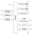
- FIG. 3 is a block diagram showing an input / output relationship of a main controller that mainly constitutes a control system of an exposure apparatus. It is sectional drawing of the support apparatus which concerns on a modification.
- FIG. 1 schematically shows a configuration of an exposure apparatus 10 according to an embodiment.
- the exposure apparatus 10 is a step-and-scan projection exposure apparatus, a so-called scanner.
- a projection optical system 16b is provided.
- the direction parallel to the optical axis AX of the projection optical system 16b is the Z-axis direction
- the reticle is in a plane perpendicular to the Z-axis direction.
- the direction in which the wafer is relatively scanned is the Y-axis direction
- the direction orthogonal to the Z-axis and the Y-axis is the X-axis direction
- the rotation (tilt) directions around the X-axis, Y-axis, and Z-axis are ⁇ x, ⁇ y, And the ⁇ z direction will be described.
- the exposure apparatus 10 includes an illumination system 12, a reticle stage 14, a projection unit 16, a wafer stage apparatus 20, and a control system thereof.
- the illumination system 12 includes, for example, a light source, an illuminance uniformizing optical system including an optical integrator, a reticle blind, and the like (both not shown) as disclosed in, for example, US Patent Application Publication No. 2003/0025890. And an illumination optical system.
- the illumination system 12 illuminates a slit-shaped illumination area IAR on the reticle R set (restricted) by a reticle blind (also called a masking system) with illumination light (exposure light) IL with substantially uniform illuminance.
- a reticle blind also called a masking system
- illumination light IL Exposure light
- ArF excimer laser light Wavelength 193 nm
- the reticle stage 14 holds a reticle R having a circuit pattern or the like formed on a pattern surface (the surface on the ⁇ Z side in FIG. 1) by, for example, vacuum suction.
- the reticle stage 14 can be driven with a predetermined stroke in the scanning direction (Y-axis direction) by a reticle stage drive system 13 (not shown in FIG. 1, see FIG. 3) including a linear motor, for example, and the X-axis and ⁇ z. It can be driven minutely in the direction.
- Position information (including rotation amount information in the ⁇ z direction) of the reticle stage 14 in the XY plane is, for example, a reticle stage position measurement system 15 (not shown in FIG. 1) including a laser interferometer system (or two-dimensional encoder system). 3) is obtained by the main controller 50 (see FIG. 3).
- the projection unit 16 is disposed below the reticle stage 14 ( ⁇ Z side).
- the projection unit 16 includes a lens barrel 16a and a projection optical system 16b held in the lens barrel 16a.
- a projection optical system 16b for example, a refractive optical system including a plurality of optical elements (lens elements) arranged along the optical axis AX is used.
- the projection optical system 16b is, for example, both-side telecentric and has a predetermined projection magnification (for example, 1/4 times, 1/5 times, or 1/8 times).
- the reticle in which the first surface (object surface) of the projection optical system 16b and the pattern surface are substantially coincided with each other is arranged. Due to the illumination light IL that has passed through R, a reduced image of the circuit pattern of the reticle R in the illumination area IAR (a reduced image of a part of the circuit pattern) passes through the projection optical system 16b, and the second surface of the projection optical system 16b.
- an exposure area IA that is conjugated to the illumination area IAR on the wafer W, which is disposed on the (image plane) side and on which a resist (sensitive agent) is applied.
- the reticle R moves relative to the illumination area IAR (illumination light IL) in the scanning direction, and the wafer W moves relative to the exposure area IA (illumination light IL).
- scanning exposure of one shot area (partition area) on the wafer W is performed, and the pattern of the reticle R is transferred to the shot area.
- the pattern of the reticle R is generated on the wafer W by the illumination system 12 and the projection optical system 16b, and the sensitive layer (resist layer) on the wafer W is exposed on the wafer W by the illumination light IL. That pattern is formed.
- the wafer stage apparatus 20 includes a surface plate 22, a wafer stage 24, a wafer stage drive system 26 (not shown in FIG. 1, refer to FIG. 3), a surface plate trim motor 28, and the like.
- the surface plate 22 is a rectangular plate-like member having the Y-axis direction as the longitudinal direction in plan view (viewed from the + Z direction), and a plurality of support devices such that the upper surface is substantially parallel to the XY plane (horizontal plane). 30 is supported non-contact from below.
- four support devices 30 are provided so that the vicinity of the four corners of the surface plate 22 can be supported.
- FIG. 1 for example, two of the four support devices 30 on the + X side are provided. Only the other two are hidden behind the two support devices 30 on the + X side. The configuration and function of the support device 30 will be described later.
- the surface plate 22 can be configured to be provided with a weight (not shown) so as to increase its own weight in order to function as a counter mass of the wafer stage 24.
- the surface plate 22 is provided with a plurality of coil units 26a in a matrix in a plan view in the region on the upper surface side inside the platen 22.
- the magnitude and direction of the current supplied to each of the plurality of coil units 26a is controlled by the main controller 50 (not shown in FIG. 1, see FIG. 3).
- the wafer stage 24 is made of a box-shaped (cuboid) member, and holds the wafer W placed on the upper surface by, for example, vacuum suction.
- a plurality of magnet units 26 b are arranged in a region on the bottom surface (surface facing the top surface of the surface plate 22) of the wafer stage 24.
- the wafer stage drive system 26 (not shown in FIG. 1, refer to FIG. 3) includes a moving magnet type planar motor including a plurality of magnet units 26b and a plurality of coil units 26a.
- the wafer stage 24 is driven with respect to the surface plate 22 by electromagnetic force (Lorentz force) acting between the plurality of magnet units 26b and the coil unit 26a corresponding to the magnet unit 26b.
- the wafer stage 24 is moved to the surface plate 22 with 6 degrees of freedom by the Lorentz force.
- a so-called 6 DOF (degrees of ⁇ freedom) planar motor that can be appropriately driven in the direction (X-axis direction, Y-axis direction, Z-axis direction, ⁇ x direction, ⁇ y direction, and ⁇ z direction) is used.
- main controller 50 (not shown in FIG. 1; see FIG. 3) uses wafer stage drive system 26 (not shown in FIG. 1, see FIG. 3) to move wafer stage 24 on surface plate 22 X.
- the position information of the wafer stage 24 in the direction of six degrees of freedom includes, for example, a wafer stage position measurement including a two-dimensional (or three-dimensional) encoder system or an optical interferometer system (or a system combining an encoder system and an optical interferometer system). It is calculated
- the configuration of the wafer stage position measurement system 27 is not particularly limited as long as the position information in the 6DOF direction of the wafer stage 24 can be obtained with a desired resolution.
- the wafer stage drive system 26 (planar motor) is used along the horizontal plane with respect to the wafer stage 24 on the surface plate 22.
- the driving force is applied (in the X-axis and / or Y-axis direction)
- the reaction force of the driving force is applied to the surface plate 22 in the direction opposite to the wafer stage 24 in the horizontal plane.
- the surface plate 22 is supported in a non-contact manner by the plurality of support devices 30, the surface plate 22 moves in the direction opposite to the wafer stage 24 in the horizontal plane according to the momentum conservation law. To absorb. Thereby, generation
- the surface plate trim motor 28 is used to move the surface plate 22 to a predetermined position. For example, when the surface plate 22 moves along the XY plane by the reaction force, the surface plate 22 can be returned to a predetermined position.
- a linear motor for example, a voice coil motor
- a stator 28a installed on the floor 100 via a support column 28c and a mover 28b fixed to the side surface of the surface plate 22 is used. It is used.
- FIG. 1 only one Y trim motor is shown as a representative. However, as the surface plate trim motor 28, an X trim motor for driving the surface plate 22 in the X axis direction, and the surface plate 22 as the Y axis.
- a plurality of Y trim motors for driving in the direction are provided.
- the position information (including the rotation amount information in the ⁇ z direction) of the surface plate 22 in the XY plane is, for example, a surface plate position measurement system 23 (not shown in FIG. 1, including a laser interferometer system (or a two-dimensional encoder system)). 3), and the main controller 50 appropriately uses a plurality of surface plate trim motors 28 based on the output of the surface plate position measurement system 23.
- the surface plate 22 is moved to a predetermined position.
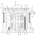
- the support device 30 includes a housing 32 including a main body 32a and a lid 32b, an air pad 36, a center shaft 38, a counter mass 40, a compression coil spring 42, and a plurality of counter mass motors 44. , And a plurality of trim motors 46.
- the main body portion 32a is formed of a bottomed cylindrical member having an upper portion (+ Z side end portion) opened, and is installed on the floor 100.
- the lid body 32b is made of a disk-like member disposed substantially parallel to the horizontal plane, and is inserted into the opening of the main body portion 32a.
- the outer diameter of the lid 32b is set smaller than the inner diameter of the main body 32a, and a gap is formed between the inner wall surface of the main body 32a and the outer peripheral end of the lid 32b.
- a gap (opening) formed between the main body portion 32a and the lid body 32b is closed by, for example, a diaphragm 34 made of a metallic film formed in a ring shape, and the lid body 32b is closed to the main body portion 32a.
- a small amount of movement is possible in the Z-axis direction.
- the housing 32 (the main body 32a, the lid 32b, and the diaphragm 34) forms a gas chamber 31 that is substantially airtight.
- the main body 32a is filled with a pressurized gas (for example, air) that is set higher than the external pressure.
- the pressure in the gas chamber 31 is set to, for example, 0.3 to 0.3 by the main controller 50 (see FIG. 3) using an internal pressure control system 33 (not shown in FIG. 1, see FIG. 3) including an electromagnetic regulator (not shown). It is controlled to about 0.4 MPa.
- the support device 30 generates a force (first force) for supporting the surface plate 22 by the action of the pressurized gas filled in the gas chamber 31 and the diaphragm 34, and the surface plate 22 and the illumination system 12, It functions as an anti-vibration device (vibration damping device) that physically (vibratingly) separates the reticle stage 14 and the projection unit 16.
- the air pad 36 is made of, for example, a disk-shaped member made of a porous member, and is fixed to the upper surface of the lid 32b. With the support device 30 supporting the surface plate 22 from below, the upper surface of the air pad 36 faces the lower surface of the surface plate 22.
- the air pad 36 is connected to a pressurized gas supply device (not shown).
- the support device 30 supports the surface plate 22 in a non-contact manner by a static pressure of a pressurized gas (for example, air) ejected from the air pad 36 toward the lower surface of the surface plate 22. Accordingly, the surface plate 22 is movable along the XY plane with respect to the plurality of support devices 30 (see FIG. 1).
- a pressurized gas for example, air
- the air pads 36 may be provided separately.
- the surface plate 22 may be supported by a configuration in which three air pads having a smaller diameter are provided on the lid 32b instead of one air pad. . It is necessary to improve the flatness of the surface of the air pad facing the surface plate 22, but using a small-diameter air pad has the advantage of facilitating processing during manufacture.
- the center shaft 38 is formed of a columnar member extending in the Z-axis direction, and a lower end portion is connected to a bottom center portion of the main body portion 32a.
- the longitudinal direction (Z-axis direction) dimension of the center shaft 38 is set to be shorter than the height direction (Z-axis direction) dimension of the main body portion 32a, and the upper end portion of the center shaft 38 is independent of the Z position of the lid 32b.
- a predetermined gap (clearance, gap) is formed between the lower surface of the lid 32b.
- the counter mass 40 is made of, for example, a cylindrical member made of a metal material or the like, and a through hole 40a penetrating in the Z-axis direction is formed at the center.
- the outer diameter of the counter mass is set to be smaller than the inner diameter of the housing 32, and a gap is formed between the inner wall surface of the main body 32 a and the outer peripheral surface of the counter mass 40.
- An air slider 41 made of a cylindrical member is integrally fixed to the inner wall surface forming the through hole 40a.
- the center shaft 38 is inserted on the inner diameter side of the air slider 41.
- a minute gap is formed between the outer peripheral surface of the center shaft 38 and the inner peripheral surface of the air slider 41.
- the air slider 41 is formed of, for example, a porous member, and is connected to a pressurized gas supply device (not shown) disposed outside the support device 30.
- the counter mass 40 is movable in the Z-axis direction along the center shaft 38 in a non-contact state by the static pressure of the pressurized gas ejected from the air slider 41 to the outer peripheral surface of the center shaft 38.
- the compression coil spring 42 is housed inside the main body 32a and supports the weight of the counter mass 40 from below.
- the outer diameter of the compression coil spring 42 is substantially the same as that of the counter mass 40, and the center shaft 38 is inserted inside the compression coil spring 42.
- the plurality of counter mass motors 44 are provided in the main body portion 32a and at least three (for example, four in this embodiment) around the center axis of the center shaft 38 at a predetermined interval.
- Each of the plurality of counter mass motors 44 includes a coil unit 44a and a magnet unit 44b.
- the coil unit 44a is fixed to the lower surface of the lid 32b via a support member 45 made of a rod-shaped member extending in the Z-axis direction and having an end on the + Z side connected to the lower surface of the lid 32b. Further, the coil unit 44 a is inserted into a recess 40 b formed on the upper surface of the counter mass 40 in a non-contact state with the counter mass 40.
- At least three recesses 40b are formed around the Z axis at predetermined intervals.
- the magnitude and direction of the current supplied to the coil units 44a of each of the plurality of counter mass motors 44 are synchronously controlled by the main controller 50 (not shown in FIG. 2, see FIG. 3).
- the magnet unit 44b is fixed to a wall surface portion forming the recess 40b and facing the coil unit 44a.
- the plurality of trim motors 46 are provided in the body portion 32a and at least three (for example, four in this embodiment) around the center axis of the center shaft 38 at a predetermined interval.
- Each of the plurality of trim motors 46 includes a coil unit 46a and a magnet unit 46b.
- the coil unit 46a is fixed to the bottom surface portion of the main body portion 32a via a support member 47 made of a rod-shaped member extending in the Z-axis direction and connected to the bottom surface portion of the main body portion 32a.
- the coil unit 46 a is inserted into a recess 40 c formed on the lower surface of the counter mass 40 in a non-contact state with the counter mass 40.
- At least three concave portions 40c are formed around the Z axis at a predetermined interval.
- the magnitude and direction of the current supplied to the coil units 46a of each of the plurality of trim motors 46 are synchronously controlled by the main controller 50 (not shown in FIG. 2, see FIG. 3).
- the magnet unit 46b is a wall surface portion that forms the recess 40c and is fixed to a portion facing the coil unit 46a.
- the plurality of counter mass motors 44 and the plurality of trim motors 46 have different radial distances from the center of the center shaft 38. Specifically, the plurality of trim motors 46 are disposed closer to the center shaft 38 than the plurality of counter mass motors 44. Thereby, the thickness of the counter mass 40 is suppressed and the support apparatus 30 is comprised compactly.
- each of the plurality of support devices 30 has substantially the same configuration and function except for the arrangement, but is independently controlled by the main control device 50.
- the plurality of counter mass motors 44 included in each of the plurality of support devices 30 are controlled independently of each other by the main controller 50 and generate a force in the Z-axis direction (second force).
- the plurality of trim motors 46 included in each of the plurality of support devices 30 are controlled independently from each other by the main control device 50.
- FIG. 3 is a block diagram showing the input / output relationship of the main controller 50 that centrally configures the control system of the exposure apparatus 10 and performs overall control of each component.
- the main controller 50 includes a workstation (or a microcomputer) and the like, and comprehensively controls each part of the exposure apparatus 10.
- the reticle R and the wafer W are loaded on the reticle stage 14 and the wafer stage 24, respectively, and reticle alignment, baseline measurement, and wafer alignment (for example, predetermined preparatory work such as EGA (Enhanced Global Alignment) is performed.
- the wafer stage 24 is driven to the acceleration start position for exposure to the first shot area of the wafer W, and the position of the reticle R is set to the acceleration start position.
- the reticle stage 14 is driven.
- the reticle stage 14 and the wafer stage 24 are synchronously driven along the Y-axis direction, whereby the first shot area on the wafer W is exposed.
- exposure of all shot areas on the reticle is performed, whereby the exposure of the wafer W is completed.
- the wafer stage 24 is appropriately driven in the direction of 6 degrees of freedom on the surface plate 22 by a wafer stage drive system 26 (see FIG. 3) including a planar motor.
- the main controller 50 controls the pressure in the gas chamber 31 of each of the plurality of support devices 30 via the internal pressure control system 33 based on the measurement value of a pressure sensor (not shown). The propagation of vibration between the floor surface 100 (see FIG. 1) and the surface plate 22 is suppressed. Further, in parallel with the pressure control in the gas chamber 31, the main controller 50 moves the surface plate 22 in the ⁇ Z direction according to the output of an acceleration sensor (not shown) that detects vibration of the surface plate 22.
- the lid 32b (and the air pad 36) is driven in the + Z direction (the direction opposite to the surface plate 22) with respect to the main body 32a by using the second force generated by the plurality of counter mass motors 44. By doing so, the vibration of the surface plate 22 is suppressed.
- the magnet unit 44b of each of the plurality of counter mass motors 44 is fixed to the counter mass 40 in the support device 30.
- a force in the ⁇ Z direction acts on the counter mass 40. Since the counter mass 40 is supported by the compression coil spring 42 in a state where the position in the Z-axis direction is not constrained, the counter mass motor is moved in the ⁇ Z direction along the center shaft 38 by the momentum conservation law.
- the drive reaction force from 44 is absorbed, whereby the drive reaction force is propagated to the floor 100 and the occurrence of vibration due to the drive reaction force is suppressed.
- the main controller 50 controls the plurality of trim motors 46 so that the vertical movement of the counter mass 40 due to the spring property of the compression coil spring 42 is suppressed. Used to control the Z position of the counter mass 40. Thereby, the posture of the counter mass 40 (that is, the magnet unit 44b of each of the plurality of counter mass motors 44) is stabilized, and the above-described vibration isolation operation can be performed with high accuracy.
- the wafer stage 24 is appropriately driven (accelerated) on the surface plate 22 in the X-axis direction and / or the Y-axis direction by a wafer stage drive system 26 (see FIG. 3) including a flat motor. Or a deceleration), a Lorentz force (electromagnetic force) in a direction parallel to the XY plane is generated between the coil unit 26a built in the surface plate 22 and the magnet unit 26b built in the wafer stage 24. .
- the coil unit 26a is disposed below the upper surface of the surface plate 22, and the magnet unit 26b is disposed above the lower surface of the wafer stage 24. Therefore, the Lorentz force is constant. It occurs between the upper surface of the board 22 and the lower surface of the wafer stage 24.
- the center of gravity of the wafer stage 24 of the present embodiment is located on the + Z side with respect to the point of action of the Lorentz force, the center of gravity of the wafer stage 24 is caused by the Lorentz force acting on the magnet unit 26b.
- a moment (so-called pitching moment) about an axis perpendicular to the advancing direction of the wafer stage 24 is applied.
- the position of the center of gravity of the surface plate 22 is located on the ⁇ Z side with respect to the point of application of the Lorentz force, the surface plate 22 also has the center of gravity centered on the wafer due to the Lorentz force acting on the coil unit 26a.
- a pitching moment in the same direction as the pitching moment acting on the stage 24 acts.
- the pitching moment causes at least one of the plurality of support devices 30 to have a downward force in the gravity direction ( Hereinafter, it is called a pitching force.
- the magnitude of the pitching force acting on the support device 30 varies depending on the position and acceleration of the wafer stage 24, but the output of the wafer stage position measurement system 27 (see FIG. 3) and the wafer stage 24 are driven (acceleration). Or based on the acceleration information when decelerating) (or after the fact in real time).
- the main control device 50 appropriately drives a plurality of counter mass motors 44 included in the support device 30 on which the pitching force acts among the plurality of support devices 30, and is approximately the same size as the pitching force (downward force in the gravity direction).
- An upward force in the gravity direction (+ Z direction) is applied to the lid 32b of the support device 30.
- the pitching force is canceled (cancelled), and the occurrence of vibration due to the direct transmission of the pitching force to the floor 100 is suppressed.
- the downward force in the gravitational direction with respect to the support device 30 is not limited to that caused by the pitching moment, and acts as a reaction force on the surface plate 22 even when the wafer stage 24 is driven in the + Z direction (or the ⁇ x and ⁇ y directions). Therefore, the same control may be performed at that time.
- the support device 30 functions as a vibration isolator that suppresses the propagation of vibration between the surface plate 22 and the floor 100, and the pitching force that acts on the floor 100 from the surface plate 22. It has a function as a counter mass device which suppresses.
- the magnet unit 44 b that is a stator of the counter mass motor 44 is fixed to the counter mass 40, the driving reaction force of the counter mass motor 44 is not transmitted directly to the floor 100. Therefore, a decrease in exposure accuracy due to the occurrence of vibration is suppressed.
- elements for exhibiting the vibration isolator function and the counter mass device function are provided in one main body 32a. Therefore, the support device 30 can be made compact and the footprint of the exposure apparatus 10 can be reduced. Furthermore, since the element is almost sealed in the main body 32a, the exposure space of the wafer is prevented from being contaminated by the element.
- the configuration of the exposure apparatus 10 of the above embodiment can be changed as appropriate.
- the main body 32a and the lid 32b of the housing 32 are connected by the diaphragm 34, but the present invention is not limited to this.
- the lid 32b can be slightly moved in the Z-axis direction with respect to the main body 32a, and the internal space formed by the main body 32a and the lid 32b can be airtight to ensure the function as a vibration isolator.
- the main body 62a and the lid 62b may be connected using the bellows 64, as in the case 62 of the support device 60 shown in FIG.
- the counter mass 40 is supported from below by the compression coil spring 42 having substantially the same diameter as the counter mass 40.
- the spring configuration ( The size, arrangement, number, etc.) can be changed as appropriate.
- a plurality of compression coil springs 72 having a smaller diameter than the compression coil spring 42 of the above-described embodiment are arranged at predetermined intervals around the Z axis (in the support device 60 shown in FIG. 3) It may be arranged. In this case, as shown in FIG.
- a recess 70d is formed on the lower surface of the counter mass 70, and a part of the compression coil spring 72 is inserted into the recess 70d in a non-contact state with the counter mass 70.
- a counter mass 40 may be supported from below by using a so-called air spring.
- the counter mass 40 is engaged with the center shaft 38 so as to be movable in the Z-axis direction in a non-contact state via the air slider 41.
- the present invention is not limited to this. is not.
- a ball spline device extendends in the Z-axis direction
- a center shaft 68 formed with a Z groove (not shown) and a pair of sleeves 71 having a plurality of balls (not shown) fixed to the counter mass 70 and inserted into the Z groove).
- the cross section of the center shaft 38 (or 68) is not limited to a circle, but may be other shapes such as a rectangle.
- the radial position around the center shaft 38 is different between the counter mass motor 44 and the trim motor 46 (the trim motor 46 is more than the counter mass motor 44.
- the present invention is not limited to this.
- the counter motor 74 and the trim motor 76 may be configured to overlap in the vertical direction (being symmetrical in the vertical direction).
- the planar motor constituting the wafer stage drive system is a 6 DOF drive type, but is not limited to this, and is a 3 DOF (X axis direction, Y axis direction, and ⁇ z direction) drive type.
- an air bearing may be attached to the lower surface of the wafer stage 24, and the wafer stage 24 may be lifted (air floating) by the static pressure of the pressurized gas ejected from the air bearing to the upper surface of the surface plate 22.
- the planar motor may be a moving coil type.
- the surface plate 22 is configured to be movable only in the X-axis and / or Y-axis directions.
- the present invention is not limited to this, and the surface plate 22 can be rotated by a small amount in the ⁇ x and ⁇ y directions. It may be configured.
- the moment of inertia of the surface plate 22 can reduce the pitching force acting on the support device 30 when the wafer stage 24 is driven, and the force generated by the plurality of counter mass motors 44 is applied to the above embodiment. Smaller than that.
- the illumination light IL is not limited to ArF excimer laser light (wavelength 193 nm), but may be ultraviolet light such as KrF excimer laser light (wavelength 248 nm) or vacuum ultraviolet light such as F 2 laser light (wavelength 157 nm). good.
- ultraviolet light such as KrF excimer laser light (wavelength 248 nm) or vacuum ultraviolet light such as F 2 laser light (wavelength 157 nm).
- vacuum ultraviolet light for example, erbium.
- a harmonic which is amplified by a fiber amplifier doped with (or both erbium and ytterbium) and wavelength-converted into ultraviolet light using a nonlinear optical crystal may be used.
- the wavelength of the illumination light IL is not limited to light of 100 nm or more, and light having a wavelength of less than 100 nm may be used.
- EUV Extreme Ultraviolet
- a soft X-ray region for example, a wavelength region of 5 to 15 nm.
- the above-described embodiment can also be applied to an EUV exposure apparatus using the above.
- the above embodiment can be applied to an exposure apparatus that uses charged particle beams such as an electron beam or an ion beam.
- the projection optical system in the exposure apparatus of the above embodiment may be not only a reduction system but also any of the same magnification and enlargement systems, and the projection optical system 16b may be any of a reflection system and a catadioptric system as well as a refraction system.
- the projected image may be an inverted image or an erect image.
- a light transmissive mask in which a predetermined light shielding pattern (or phase pattern / dimming pattern) is formed on a light transmissive substrate is used.
- a predetermined light shielding pattern or phase pattern / dimming pattern
- a light transmissive substrate is used.
- a variable shaping mask, an active mask that forms a transmission pattern, a reflection pattern, or a light emission pattern.
- a DMD Digital Micro-mirror Device
- spatial light modulator spatial light modulator
- the wafer stage apparatus 20 in which one wafer stage 24 is disposed on the surface plate 22 has been described.
- the number and type of moving bodies disposed on the surface plate 22 can be changed as appropriate.
- the embodiment described above can also be applied to a wafer stage apparatus that includes a wafer stage and a measurement stage.
- an exposure operation is performed in a state where a liquid (for example, pure water) is filled between the projection optical system and an object to be exposed (for example, a wafer).
- a liquid for example, pure water
- an object to be exposed for example, a wafer.
- the above embodiment can also be applied to a so-called immersion exposure apparatus.
- an exposure apparatus (lithography system) that forms a line-and-space pattern on a wafer W by forming interference fringes on the wafer W.
- the above embodiment can also be applied.
- the above-described embodiment can also be applied to a step-and-stitch reduction projection exposure apparatus that synthesizes a shot area and a shot area.
- two reticle patterns are synthesized on a wafer via a projection optical system, and 1 on the wafer by one scan exposure.
- the above embodiment can also be applied to an exposure apparatus that performs double exposure of two shot areas almost simultaneously.
- the object on which the pattern is to be formed in the above embodiment is not limited to the wafer, but may be another object such as a glass plate, a ceramic substrate, a film member, or a mask blank. good.
- the application of the exposure apparatus is not limited to the exposure apparatus for semiconductor manufacturing, for example, an exposure apparatus for liquid crystal that transfers a liquid crystal display element pattern to a square glass plate, an organic EL, a thin film magnetic head,
- the present invention can be widely applied to an exposure apparatus for manufacturing an image sensor (CCD or the like), a micromachine, a DNA chip, and the like.
- an image sensor CCD or the like
- a micromachine a DNA chip
- the like in order to manufacture reticles or masks used in not only microdevices such as semiconductor elements but also light exposure apparatuses, EUV exposure apparatuses, X-ray exposure apparatuses, electron beam exposure apparatuses, etc., glass substrates or silicon wafers, etc.
- the above embodiment can also be applied to an exposure apparatus that transfers a circuit pattern.
- An electronic device such as a semiconductor element includes a step of designing a function / performance of a device, a step of manufacturing a reticle based on the design step, a step of manufacturing a wafer from a silicon material, and an exposure apparatus (pattern formation) according to the above-described embodiment.
- Apparatus and a lithography step for transferring a mask (reticle) pattern onto the wafer by the exposure method, a development step for developing the exposed wafer, and an etching step for removing the exposed member other than the portion where the resist remains by etching It is manufactured through a resist removal step for removing a resist that has become unnecessary after etching, a device assembly step (including a dicing process, a bonding process, and a packaging process), an inspection step, and the like.
- the exposure method described above is executed using the exposure apparatus of the above embodiment, and a device pattern is formed on the wafer. Therefore, a highly integrated device can be manufactured with high productivity.
- the support device of the present invention is suitable for supporting a predetermined member.
- the moving body device of the present invention is suitable for moving the moving body on the base member.
- the exposure apparatus of the present invention is suitable for forming a predetermined pattern on an object.
- the device manufacturing method of the present invention is suitable for the production of micro devices.
Landscapes
- Physics & Mathematics (AREA)
- General Physics & Mathematics (AREA)
- Exposure And Positioning Against Photoresist Photosensitive Materials (AREA)
- Container, Conveyance, Adherence, Positioning, Of Wafer (AREA)
- Exposure Of Semiconductors, Excluding Electron Or Ion Beam Exposure (AREA)
Abstract
定盤(22)を支持する支持装置(30)は、筐体(32)と、前記筐体(32)内に設けられ、前記定盤(22)が-Z側に移動して前記筐体(32)の蓋体(32b)を押圧した場合に、前記蓋体(32b)に対して+Z方向の力を作用させるカウンタマス用モータ(44)と、前記筐体(32)に設けられ、前記カウンタマス用モータ(44)が前記+Z方向の力を前記蓋体(32b)に作用させる際に該力の反力により-Z方向に移動するカウンタマス(40)と、を備える。
Description
本発明は、支持装置、移動体装置、露光装置、及びデバイス製造方法に係り、更に詳しくは、所定の支持対象物を下方から支持する支持装置、該支持装置に支持されたベース部材上を移動する移動体を含む移動体装置、該移動体装置を含む露光装置、及び該露光装置を用いるデバイス製造方法に関する。
従来、半導体素子(集積回路等)、液晶表示素子等の電子デバイス(マイクロデバイス)を製造するリソグラフィ工程では、主として、ステップ・アンド・リピート方式の投影露光装置(いわゆるステッパ)、あるいはステップ・アンド・スキャン方式の投影露光装置(いわゆるスキャニング・ステッパ(スキャナとも呼ばれる))などが用いられている。
この種の露光装置としては、露光対象物体であるウエハ又はガラスプレート等の基板(以下、ウエハと総称する)を保持する基板ステージを、該基板ステージが有する可動子と、所定のベース部材が有する固定子とを含む平面モータを用いて2次元駆動する基板ステージ装置を備えたものが知られている(例えば、特許文献1参照)。
ここで、基板ステージ装置において、平面モータを用いて基板ステージをベース部材上で駆動する際、その駆動力(推力)に起因して、基板ステージの進行方向に直交する軸線回りのモーメント(いわゆるピッチングモーメント)がベース部材に作用し、該モーメントに起因して生じる振動が露光精度を悪化させるおそれがある。
本発明は、上述の事情の下でなされたもので、第1の観点からすると、所定の支持部に対して、支持対象物を所定方向に支持する支持装置であって、前記支持対象物に対向する対向部材と、前記支持のための第1の力を発生させる流体が供給される筐体と、を有する第1部材と、少なくとも一部が前記第1部材に設けられ、前記対向部材に対して、前記所定方向に沿った方向の第2の力を作用させるアクチュエータと、前記対向部材に対して前記所定方向に沿って相対移動可能に支持され、前記アクチュエータが前記第2の力を前記対向部材に作用させる際に、該第2の力の向きとは反対の方向に移動する移動部材と、を備える支持装置である。
これによれば、アクチュエータが対向部材に第2の力を作用させる際、該第2の力の向きとは反対の方向に移動部材が対向部材と相対移動するので、所定の支持部に対する反力(あるいは反力に起因する振動)の伝播が抑制される。
本発明は、第2の観点からすると、ベース部材と、前記ベース部材上を移動可能な移動体と、前記ベース部材を前記支持対象物とする本発明の支持装置と、を備える移動体装置である。
これによれば、移動体をベース部材上で移動させる際に生じる振動などが支持装置により抑制されるので、移動体の位置制御を精度良く行うことができる。
本発明は、第3の観点からすると、所定の物体が前記移動体に保持される本発明の移動体装置と、前記物体にエネルギビームを用いて所定のパターンを形成するパターン形成装置と、を備える露光装置である。
本発明は、第4の観点からすると、本発明の露光装置を用いて前記物体を露光することと、露光された前記物体を現像することと、を含むデバイス製造方法である。
以下、一実施形態について、図1~図3を用いて説明する。
図1には、一実施形態に係る露光装置10の構成が概略的に示されている。露光装置10は、ステップ・アンド・スキャン方式の投影露光装置、いわゆるスキャナである。後述するように、本実施形態では、投影光学系16bが設けられており、以下においては、投影光学系16bの光軸AXと平行な方向をZ軸方向、これに直交する面内でレチクルとウエハとが相対走査される方向をY軸方向、Z軸及びY軸に直交する方向をX軸方向とし、X軸、Y軸、及びZ軸回りの回転(傾斜)方向をそれぞれθx、θy、及びθz方向として説明を行う。
露光装置10は、照明系12、レチクルステージ14、投影ユニット16、ウエハステージ装置20、及びこれらの制御系を備えている。
照明系12は、例えば米国特許出願公開第2003/0025890号明細書などに開示されるように、光源と、オプティカルインテグレータ等を含む照度均一化光学系、及びレチクルブラインド等(いずれも不図示)を有する照明光学系と、を含む。照明系12は、レチクルブラインド(マスキングシステムとも呼ばれる)で設定(制限)されたレチクルR上のスリット状の照明領域IARを、照明光(露光光)ILによりほぼ均一な照度で照明する。照明光ILとして、一例として、ArFエキシマレーザ光(波長193nm)が用いられている。
レチクルステージ14は、パターン面(図1における-Z側の面)に回路パターンなどが形成されたレチクルRを、例えば真空吸着により保持している。レチクルステージ14は、例えばリニアモータ等を含むレチクルステージ駆動系13(図1では不図示、図3参照)によって、走査方向(Y軸方向)に所定のストロークで駆動可能、且つX軸、及びθz方向に微小駆動可能となっている。レチクルステージ14のXY平面内の位置情報(θz方向の回転量情報を含む)は、例えばレーザ干渉計システム(あるいは2次元エンコーダシステム)を含むレチクルステージ位置計測系15(図1では不図示、図3参照)を用いて、主制御装置50(図3参照)によって求められる。
投影ユニット16は、レチクルステージ14の下方(-Z側)に配置されている。投影ユニット16は、鏡筒16aと、鏡筒16a内に保持された投影光学系16bと、を含む。投影光学系16bとしては、例えば光軸AXに沿って配列される複数の光学素子(レンズエレメント)から成る屈折光学系が用いられる。投影光学系16bは、例えば両側テレセントリックで、所定の投影倍率(例えば1/4倍、1/5倍又は1/8倍など)を有する。
このため、照明系12からの照明光ILによってレチクルR上の照明領域IARが照明されると、投影光学系16bの第1面(物体面)とパターン面とがほぼ一致して配置されるレチクルRを通過した照明光ILにより、投影光学系16bを介してその照明領域IAR内のレチクルRの回路パターンの縮小像(回路パターンの一部の縮小像)が、投影光学系16bの第2面(像面)側に配置される、表面にレジスト(感応剤)が塗布されたウエハW上の前記照明領域IARに共役な領域(以下、露光領域とも呼ぶ)IAに形成される。そして、レチクルステージ14とウエハステージ24との同期駆動によって、照明領域IAR(照明光IL)に対してレチクルRが走査方向に相対移動するとともに、露光領域IA(照明光IL)に対してウエハWが走査方向に相対移動することで、ウエハW上の1つのショット領域(区画領域)の走査露光が行われ、そのショット領域にレチクルRのパターンが転写される。すなわち、本実施形態では、照明系12、及び投影光学系16bによってウエハW上にレチクルRのパターンが生成され、照明光ILによるウエハW上の感応層(レジスト層)の露光によってウエハW上にそのパターンが形成される。
ウエハステージ装置20は、定盤22、ウエハステージ24、ウエハステージ駆動系26(図1では不図示。図3参照)、及び定盤トリムモータ28等を備えている。
定盤22は、平面視で(+Z方向から見て)Y軸方向を長手方向とする矩形の板状部材であって、上面がXY平面(水平面)にほぼ平行となるように複数の支持装置30により下方から非接触支持されている。複数の支持装置30は、定盤22の4隅部近傍を支持可能なように、例えば4つ設けられている、なお、図1では、例えば4つの支持装置30のうち、+X側の2つのみが示され、他の2つは上記+X側の2つの支持装置30に対して紙面奥側に隠れている。支持装置30の構成、及び機能については後述する。また、定盤22は、ウエハステージ24のカウンタマスとして機能させるために、自身の重量を増加させるよう錘(不図示)が設けられるような構成とすることができる。
定盤22には、その内部の上面側の領域に、複数のコイルユニット26aが平面視でマトリクス状に設けられている。複数のコイルユニット26aそれぞれに供給される電流の大きさ及び方向は、主制御装置50(図1では不図示。図3参照)によって制御される。
ウエハステージ24は、箱形(直方体状)の部材から成り、上面に載置されたウエハWを、例えば真空吸着により保持する。ウエハステージ24の底面(定盤22の上面に対向する面)側の領域には、複数の磁石ユニット26bが配置されている。
ウエハステージ駆動系26(図1では不図示。図3参照)は、複数の磁石ユニット26bと、複数のコイルユニット26aとにより構成されるムービングマグネットタイプの平面モータを含む。ウエハステージ24は、複数の磁石ユニット26bと、該磁石ユニット26bに対応するコイルユニット26aとの間に作用する電磁力(ローレンツ力)により、定盤22に対して駆動される。
ここで、本実施形態において、平面モータとしては、例えば米国特許第6,452,292号明細書などに開示されるような、上記ローレンツ力によりウエハステージ24を定盤22に対して6自由度方向(X軸方向、Y軸方向、Z軸方向、θx方向、θy方向、及びθz方向)に適宜駆動することが可能な、いわゆる6DOF(degrees of freedom)駆動タイプの平面モータが用いられている。これにより、主制御装置50(図1では不図示。図3参照)は、ウエハステージ駆動系26(図1では不図示。図3参照)を用いて、ウエハステージ24を定盤22上でX軸方向、及び/又はY軸方向に(XY平面に沿って)所定の長ストロークで駆動すること、ウエハステージ24を定盤22上に所定の隙間を介して浮上(磁気浮上)させること、並びに、XY平面に沿って移動するウエハステージ24をピッチング、ヨーイング、及びローリング方向に適宜微少駆動することができる。
ウエハステージ24の6自由度方向の位置情報は、例えば2次元(あるいは3次元)エンコーダシステム、又は光干渉計システム(あるいはエンコーダシステムと光干渉計システムとを組み合わせたシステム)を含むウエハステージ位置計測系27(図1では不図示。図3参照)を用いて、主制御装置50(図3参照)によって求められる。なお、ウエハステージ位置計測系27の構成は、所望の分解能でウエハステージ24の6DOF方向の位置情報を求めることができれば、その構成は特に限定されない。
ここで、定盤22がコイルユニット26a(平面モータ固定子)を有していることから、ウエハステージ駆動系26(平面モータ)を用いて定盤22上でウエハステージ24に対して水平面に沿って(X軸、及び/又はY軸方向に)駆動力を作用させる場合、定盤22には、水平面内でウエハステージ24とは反対の方向に上記駆動力の反力が作用する。そして、定盤22が複数の支持装置30により非接触支持されていることから、定盤22は、運動量保存則により水平面内でウエハステージ24とは反対の方向に移動することにより、上記反力を吸収する。これにより、上記反力に起因する、例えば支持装置30の設置部の振動の発生などが抑制される。なお、定盤22の重量は、ウエハステージ24の重量に比べて大きい、または前記錘によって重量化することができるため、定盤22の移動量は、ウエハステージ24に比べて微少量である。
定盤トリムモータ28は、定盤22を所定の位置に移動させるために用いられる。例えば、上記反力により定盤22がXY平面に沿って移動した際に、該定盤22を所定の位置に復帰させることが可能である。定盤トリムモータ28としては、支持柱28cを介して床100上に設置された固定子28aと、定盤22の側面に固定された可動子28bとを含むリニアモータ(例えばボイスコイルモータ)が用いられている。なお、図1では、代表的にYトリムモータがひとつのみ示されているが、定盤トリムモータ28として、定盤22をX軸方向に駆動するためのXトリムモータ、定盤22をY軸方向に駆動するためのYトリムモータがそれぞれ複数設けられている。定盤22のXY平面内の位置情報(θz方向の回転量情報も含む)は、例えばレーザ干渉計システム(あるいは2次元エンコーダシステム)を含む定盤位置計測系23(図1では不図示、図3参照)を用いて、主制御装置50(図3参照)によって求められており、主制御装置50は、定盤位置計測系23の出力に基づいて複数の定盤トリムモータ28を適宜用いて定盤22を所定の位置に移動させる。
複数の支持装置30それぞれは、配置を除きほぼ同じ構成、及び機能を有している。以下、複数の支持装置30のうちのひとつについて説明する。支持装置30は、図2に示されるように、本体部32aと蓋体32bとを含む筐体32、エアパッド36、センタシャフト38、カウンタマス40、圧縮コイルばね42、複数のカウンタマス用モータ44、及び複数のトリムモータ46を有している。
本体部32aは、上部(+Z側の端部)が開口した有底円筒状の部材から成り、床100上に設置されている。蓋体32bは、水平面にほぼ平行に配置された円板状の部材から成り、本体部32aの開口内に挿入されている。蓋体32bの外径寸法は、本体部32aの内径寸法よりも小さく設定されており、本体部32aの内壁面と蓋体32bの外周端部との間には、隙間が形成されている。本体部32aと蓋体32bとの間に形成される隙間(開口)は、例えばリング状に形成された金属性の膜からなるダイヤフラム34により塞がれており、蓋体32bは、本体部32aに対してZ軸方向に微少量移動可能となっている。
筐体32(本体部32a、蓋体32b、及びダイヤフラム34)は、ほぼ気密状態の気体室31を形成している。本体部32a内には、外部の圧力よりも高く設定される加圧気体(例えば空気)が充填されている。気体室31内の圧力は、不図示の電磁レギュレータを含む内圧制御系33(図1では不図示。図3参照)を用いて、主制御装置50(図3参照)により、例えば0.3~0.4MPa程度に制御される。支持装置30は、気体室31に充填された加圧気体、及びダイヤフラム34の作用により、定盤22を支持する力(第1の力)を発生するとともに、定盤22と上記照明系12、レチクルステージ14、及び投影ユニット16などとを物理的(振動的)に分離する防振装置(振動減衰装置)として機能する。
エアパッド36は、例えば多孔質部材により形成された円板状の部材から成り、蓋体32bの上面に固定されている。支持装置30が定盤22を下方から支持した状態で、エアパッド36の上面は、定盤22の下面に対向している。エアパッド36には、不図示の加圧気体供給装置が接続されている。支持装置30は、エアパッド36から定盤22の下面に対して噴出される加圧気体(例えば空気)の静圧により、定盤22を非接触支持している。これにより、定盤22は、複数の支持装置30(図1参照)に対してXY平面に沿って移動自在となっている。エアパッド36は、各支持装置30に対して一つずつ設けられているが、複数に分けて設けるようにしてもよい。例えば、支持する定盤22の重量等に応じて、1つのエアパッドの代わりに、それよりも小径のエアパッドを蓋体32bに3つ設けた構成にして定盤22を支持するようにしてもよい。エアパッドの定盤22と対向する面は平面度をよくする必要があるが、小径のエアパッドを用いると製造時の加工が容易になるという利点がある。
センタシャフト38は、Z軸方向に延びる円柱状の部材から成り、本体部32aの底面中央部に下端部が接続されている。センタシャフト38の長手方向(Z軸方向)寸法は、本体部32aの高さ方向(Z軸方向)寸法よりも短く設定され、蓋体32bのZ位置に関わらず、センタシャフト38の上端部と蓋体32bの下面との間に所定の隙間(クリアランス、ギャップ)が形成されるようになっている。
カウンタマス40は、例えば金属材料などにより形成された円筒状の部材から成り、中央部にZ軸方向に貫通する貫通孔40aが形成されている。カウンタマスの外径寸法は、筐体32の内径寸法よりも小さく設定されており、本体部32aの内壁面とカウンタマス40の外周面との間には、隙間が形成されている。貫通孔40aを形成する内壁面には、筒状の部材から成るエアスライダ41が一体的に固定されている。センタシャフト38は、エアスライダ41の内径側に挿入されている。センタシャフト38の外周面と、エアスライダ41の内周面との間には、微少な隙間が形成されている。エアスライダ41は、例えば多孔質部材により形成され、支持装置30の外部に配置された不図示の加圧気体供給装置が接続されている。カウンタマス40は、エアスライダ41からセンタシャフト38の外周面に対して噴出される加圧気体の静圧により、非接触状態でセンタシャフト38に沿ってZ軸方向に移動自在となっている。
圧縮コイルばね42は、本体部32aの内部に収納され、カウンタマス40の自重を下方から支持している。圧縮コイルばね42の外径寸法は、カウンタマス40とほぼ同じとなっており、センタシャフト38は、圧縮コイルばね42の内側に挿通されている。
複数のカウンタマス用モータ44は、本体部32aの内部であって、センタシャフト38の中心軸回りに所定間隔で少なくとも3つ(本実施形態では、例えば4つ)設けられている。複数のカウンタマス用モータ44それぞれは、コイルユニット44aと磁石ユニット44bとを有している。コイルユニット44aは、+Z側の端部が蓋体32bの下面に接続されたZ軸方向に延びる棒状の部材から成る支持部材45を介して蓋体32bの下面に固定されている。また、コイルユニット44aは、カウンタマス40の上面に形成された凹部40b内に、カウンタマス40とは非接触の状態で挿入されている。凹部40bは、複数のカウンタマス用モータ44に対応して、Z軸回りに所定間隔で少なくとも3つ(本実施形態では、例えば4つ)形成されている。複数のカウンタマス用モータ44それぞれのコイルユニット44aに供給される電流の大きさ及び方向は、主制御装置50(図2では不図示。図3参照)によって同期制御される。磁石ユニット44bは、上記凹部40bを形成する壁面部であって、かつコイルユニット44aに対向する部分に固定されている。
複数のトリムモータ46は、本体部32aの内部であって、センタシャフト38の中心軸回りに所定間隔で少なくとも3つ(本実施形態では、例えば4つ)設けられている。複数のトリムモータ46それぞれは、コイルユニット46aと磁石ユニット46bとを有している。コイルユニット46aは、-Z側の端部が本体部32aの底面部に接続されたZ軸方向に延びる棒状の部材から成る支持部材47を介して本体部32aの底面部に固定されている。コイルユニット46aは、カウンタマス40の下面に形成された凹部40c内に、カウンタマス40とは非接触の状態で挿入されている。凹部40cは、複数のトリムモータ46に対応して、Z軸回りに所定間隔で少なくとも3つ(本実施形態では、例えば4つ)形成されている。複数のトリムモータ46それぞれのコイルユニット46aに供給される電流の大きさ及び方向は、主制御装置50(図2では不図示。図3参照)によって同期制御される。磁石ユニット46bは、上記凹部40cを形成する壁面部であって、かつコイルユニット46aに対向する部分に固定されている。
複数のカウンタマス用モータ44と複数のトリムモータ46とは、センタシャフト38の中心からの半径方向の距離が異なっている。具体的には、複数のトリムモータ46は、複数のカウンタマス用モータ44よりもセンタシャフト38側に配置されている。これにより、カウンタマス40の厚みが抑制され、支持装置30がコンパクトに構成されている。
ここで、複数の支持装置30それぞれは、配置を除き実質的に同じ構成、及び機能を有しているが、主制御装置50により互いに独立に制御される。具体的には、複数の支持装置30それぞれが有する複数のカウンタマス用モータ44は、主制御装置50により互いに独立に制御され、Z軸方向の力(第2の力)を発生させる。同様に複数の支持装置30それぞれが有する複数のトリムモータ46は、主制御装置50により互いに独立に制御される。
図3には、露光装置10の制御系を中心的に構成し、構成各部を統括制御する主制御装置50の入出力関係を示すブロック図が示されている。主制御装置50は、ワークステーション(又はマイクロコンピュータ)等を含み、露光装置10の構成各部を統括制御する。
上記のように構成された露光装置10(図1参照)では、まず、レチクルR及びウエハWが、それぞれレチクルステージ14及びウエハステージ24上にロードされ、レチクルアライメント及びベースライン計測、並びにウエハアライメント(例えばEGA(エンハンスト・グローバル・アライメント)等)などの所定の準備作業が行われる。その後、主制御装置50の管理の下、ウエハWの第1番目のショット領域に対する露光のための加速開始位置にウエハステージ24が駆動されるとともに、レチクルRの位置が加速開始位置となるように、レチクルステージ14が駆動される。そして、レチクルステージ14と、ウエハステージ24とがY軸方向に沿って同期駆動されることで、ウエハW上の第1番目のショット領域に対する露光が行われる。以後、レチクル上のすべてのショット領域に対する露光が行われることで、ウエハWの露光が完了する。
上記アライメント動作、露光動作中を含み、露光装置10では、ウエハステージ24が平面モータを含むウエハステージ駆動系26(図3参照)により定盤22上で6自由度方向に適宜駆動される。そして、主制御装置50(図3参照)は、内圧制御系33を介して複数の支持装置30それぞれの気体室31内の圧力を、不図示の圧力センサの計測値に基づいて制御することにより、床面100(図1参照)及び定盤22相互間における振動の伝搬を抑制する。また、主制御装置50は、上記気体室31内の圧力制御と並行して、定盤22の振動を検出する不図示の加速度センサの出力に応じて、定盤22が-Z方向に移動した場合に、複数のカウンタマス用モータ44が発生させた第2の力を用いて本体部32aに対して蓋体32b(及びエアパッド36)を+Z方向(定盤22とは反対の方向)に駆動することにより、定盤22の振動を抑制する。
上記複数のカウンタマス用モータ44が蓋体32bをZ軸方向に微少駆動する際、支持装置30では、複数のカウンタマス用モータ44それぞれの磁石ユニット44bがカウンタマス40に固定されていることから、カウンタマス40に-Z方向の力(以下、駆動反力と称する)が作用する。カウンタマス40は、圧縮コイルばね42によりZ軸方向の位置が拘束されていない状態で支持されているため、運動量保存則によりセンタシャフト38に沿って-Z方向に移動することによりカウンタマス用モータ44からの駆動反力を吸収し、これにより上記駆動反力が床100に伝搬すること、及び上記駆動反力に起因する振動の発生が抑制される。
カウンタマス40が駆動反力により-Z方向に移動すると、主制御装置50は、圧縮コイルばね42のばね性に起因するカウンタマス40の上下動が抑制されるように、複数のトリムモータ46を用いてカウンタマス40のZ位置を制御する。これにより、カウンタマス40(すなわち複数のカウンタマス用モータ44それぞれの磁石ユニット44b)の姿勢が安定し、精度良く上記防振動作を行うことができる。
また、上記アライメント動作、露光動作中において、ウエハステージ24が平面モータを含むウエハステージ駆動系26(図3参照)により定盤22上でX軸方向、及び/又はY軸方向に適宜駆動(加速、又は減速)される際、定盤22に内蔵されたコイルユニット26aと、ウエハステージ24に内蔵された磁石ユニット26bとの間にXY平面に平行な方向のローレンツ力(電磁力)が発生する。ここで、平面モータでは、コイルユニット26aが定盤22の上面よりも下方に配置され、且つ磁石ユニット26bがウエハステージ24の下面よりも上方に配置されていることから、上記ローレンツ力は、定盤22の上面とウエハステージ24の下面との間に発生する。
これに対し、本実施形態のウエハステージ24の重心位置が上記ローレンツ力の作用点よりも+Z側に位置することから、ウエハステージ24には、磁石ユニット26bに作用するローレンツ力により、その重心位置を中心としてウエハステージ24の進行方向に直交する軸回りのモーメント(いわゆるピッチングモーメント)が作用する。同様に、定盤22の重心位置が上記ローレンツ力の作用点よりも-Z側に位置することから、コイルユニット26aに作用するローレンツ力により、定盤22にも、その重心位置を中心としてウエハステージ24に作用するピッチングモーメントと同じ向きのピッチングモーメントが作用する。
そして、定盤22は、4隅部それぞれに対応する位置が、支持装置30により下方から支持されていることから、上記ピッチングモーメントにより、複数の支持装置30の少なくともひとつに重力方向下向きの力(以下、ピッチングフォースと称する)が作用する。ここで、支持装置30に作用するピッチングフォースの大きさは、ウエハステージ24の位置、及び加速度により異なるが、ウエハステージ位置計測系27(図3参照)の出力、及びウエハステージ24を駆動(加速、又は減速)する際の加速度情報に基づいて事前に(あるいはほぼリアルタイムで事後的に)求めることができる。
主制御装置50は、複数の支持装置30のうち、ピッチングフォースが作用する支持装置30が有する複数のカウンタマス用モータ44を適宜駆動し、上記ピッチングフォース(重力方向下向きの力)とほぼ同じ大きさの重力方向上向き(+Z方向)の力を支持装置30の蓋体32bに対して作用させる。これにより、ピッチングフォースが相殺され(打ち消され)、ピッチングフォースが直接床100に伝わることに起因する振動の発生が抑制される。
上記ピッチングフォースを打ち消すために複数のカウンタマス用モータ44が駆動された場合には、駆動反力によりカウンタマス40に重力方向下向きの駆動反力が作用する。この場合であっても、カウンタマス40が運動量保存則により重力方向下向きに移動することにより上記駆動反力が吸収され、これにより上記駆動反力に起因する振動の発生などが抑制される。また、カウンタマス40が重力方向下向きに移動すると、主制御装置50は、複数のトリムモータ46を用いてカウンタマス40の上下動を抑制する。なお、支持装置30に対する重力方向下向きの力は、ピッチングモーメントに起因するものに限られず、ウエハステージ24を+Z方向(あるいはθx、θy方向)に駆動したときにも定盤22に反力として作用するので、その際に同様の制御を行っても良い。
以上説明した本実施形態によれば、支持装置30は、定盤22と床100との間における振動の伝搬を抑制する防振装置としての機能、及び定盤22から床100に作用するピッチングフォースを抑制するカウンタマス装置としての機能を有する。そして、支持装置30では、カウンタマス用モータ44の固定子である磁石ユニット44bがカウンタマス40に固定されているので、カウンタマス用モータ44の駆動反力が直接床100に伝達しない。したがって、振動の発生に起因する露光精度の低下などが抑制される。
また、防振装置機能、及びカウンタマス装置機能を発揮させるための要素(カウンタマス40、圧縮コイルばね42、複数のカウンタマス用モータ44、及び複数のトリムモータ46)がひとつの本体部32a内に収容されているので、効率的、且つ支持装置30をコンパクトにすることができ、露光装置10のフットプリントを低減できる。さらに、前記要素が本体部32a内にほぼ密閉されているため、該要素によってウエハの露光空間が汚染されることも防止される。
なお、ウエハステージ24を定盤22上で平面モータを用いて駆動する際、例えば露光精度に影響がなければ、床100にピッチングフォースが作用しても問題がない。このような場合、支持装置30では、複数のカウンタマス用モータ44それぞれのコイルユニット44aと磁石ユニット44bとの間に発生するローレンツ力、及び複数のトリムモータ46それぞれのコイルユニット46aと磁石ユニット46bとの間に発生するローレンツ力を介して、ピッチングフォースを直接床100に作用させることもできる。
また、上記実施形態の露光装置10の構成は、適宜変更が可能である。例えば、上記実施形態に係る支持装置30において、筐体32の本体部32aと蓋体32bとは、ダイヤフラム34により接続されていたが、これに限定されるものではない。例えば、蓋体32bを本体部32aに対してZ軸方向に微少移動可能、且つ本体部32aと蓋体32bとにより形成される内部空間を気密状態にして防振装置としての機能を確保できるのであれば、図4に示される支持装置60の筐体62ように、ベローズ64を用いて本体部62aと蓋体62b(エアパッド66を含む)とを接続しても良い。
また、上記実施形態の支持装置30において、カウンタマス40は、カウンタマス40とほぼ同径の圧縮コイルばね42により下方から支持されていたが、カウンタマス40の自重をキャンセルできれば、ばねの構成(大きさ、配置、数など)は、適宜変更が可能である。例えば図4に示される支持装置60のように、上記実施形態の圧縮コイルばね42よりも小径の圧縮コイルばね72をZ軸回りに所定間隔で複数(図4に示される支持装置60では、例えば3つ)配置しても良い。この場合、図4に示されるように、カウンタマス70の下面に凹部70dを形成し、圧縮コイルばね72の一部を該凹部70d内に、カウンタマス70とは非接触の状態で挿入すると良い。また、圧縮コイルばね42(あるいは72)に換えて、例えばいわゆる空気ばねを用いてカウンタマス40(あるいは70)を下方から支持しても良い。
また、上記実施形態の支持装置30において、カウンタマス40は、センタシャフト38に対してエアスライダ41を介して非接触状態でZ軸方向に移動可能に係合していたが、これに限るものではない。例えば、カウンタマス40がセンタシャフト38に対して低摩擦でZ軸方向に移動可能となっているのであれば、図4に示される支持装置60のように、ボールスプライン装置(Z軸方向に延びるZ溝(不図示)が形成されたセンタシャフト68と、カウンタマス70に固定され、上記Z溝に挿入される複数のボール(不図示)を有する一対のスリーブ71と、を含む)を用いても良い。また、センタシャフト38(あるいは68)の断面は、円形に限られず、その他の形状、例えば矩形であっても良い。
また、上記実施形態の支持装置30において、センタシャフト38を中心とする径方向の位置がカウンタマス用モータ44とトリムモータ46とで異なるように(トリムモータ46の方がカウンタマス用モータ44よりも内径側に)配置されていたが、これに限るものではない。例えば、図4に示される支持装置60のように、カウンタモータ74とトリムモータ76とが上下方向に重なる(上下に対称となるような)構成でも良い。
なお、図4に示される支持装置60の動作は、上記実施形態に係る支持装置30とほぼ同じなので、説明を省略する。
また、上記実施形態において、ウエハステージ駆動系を構成する平面モータは、6DOF駆動タイプであったが、これに限られず、3DOF(X軸方向、Y軸方向、及びθz方向)駆動タイプであっても良く、この場合、ウエハステージ24の下面にエアベアリングを取り付け、該エアベアリングから定盤22の上面に噴出される加圧気体の静圧によりウエハステージ24を浮上(エア浮上)させると良い。また、平面モータは、ムービングコイルタイプであっても良い。
また、上記実施形態では、定盤22は、X軸及び/又はY軸方向にのみ移動可能な構成であったが、これに限られず、定盤22をθx及びθy方向に微少量回転可能に構成しても良い。この場合、定盤22の慣性モーメントにより、ウエハステージ24を駆動する際に支持装置30に作用するピッチングフォースを低減することができ、複数のカウンタマス用モータ44が発生する力が上記実施形態に比べて小さくて良い。
また、照明光ILは、ArFエキシマレーザ光(波長193nm)に限らず、KrFエキシマレーザ光(波長248nm)などの紫外光や、F2レーザ光(波長157nm)などの真空紫外光であっても良い。例えば米国特許第7,023,610号明細書に開示されているように、真空紫外光としてDFB半導体レーザ又はファイバーレーザから発振される赤外域、又は可視域の単一波長レーザ光を、例えばエルビウム(又はエルビウムとイッテルビウムの両方)がドープされたファイバーアンプで増幅し、非線形光学結晶を用いて紫外光に波長変換した高調波を用いても良い。また、照明光ILの波長は、100nm以上の光に限られず、波長100nm未満の光を用いても良く、例えば、軟X線領域(例えば5~15nmの波長域)のEUV(Extreme Ultraviolet)光を用いるEUV露光装置にも上記実施形態を適用することができる。その他、電子線又はイオンビームなどの荷電粒子線を用いる露光装置にも、上記実施形態は適用できる。
さらに、上記実施形態の露光装置における投影光学系は縮小系のみならず等倍及び拡大系のいずれでも良いし、投影光学系16bは屈折系のみならず、反射系及び反射屈折系のいずれでも良いし、この投影像は倒立像及び正立像のいずれでも良い。
また、上記実施形態においては、光透過性の基板上に所定の遮光パターン(又は位相パターン・減光パターン)を形成した光透過型マスク(レチクル)を用いたが、このレチクルに代えて、例えば米国特許第6,778,257号明細書に開示されているように、露光すべきパターンの電子データに基づいて、透過パターン又は反射パターン、あるいは発光パターンを形成する電子マスク(可変成形マスク、アクティブマスク、あるいはイメージジェネレータとも呼ばれ、例えば非発光型画像表示素子(空間光変調器)の一種であるDMD(Digital Micro-mirror Device)などを含む)を用いても良い。
また、上記実施形態では、定盤22上にひとつのウエハステージ24が配置されたウエハステージ装置20について説明したが、定盤22上に配置される移動体の数、種類は、適宜変更が可能であり、例えば米国特許出願公開第2010/0066992号明細書に開示されるようなウエハステージを2つ備えたウエハステージ装置、あるいは米国特許出願公開第2009/0268178号明細書に開示されるようなウエハステージと、計測ステージとを備えるウエハステージ装置にも、上記実施形態は適用できる。
さらに、例えば米国特許第8,004,650号明細書に開示されるような、投影光学系と露光対象物体(例えばウエハ)との間に液体(例えば純水)を満たした状態で露光動作を行う、いわゆる液浸露光装置にも上記実施形態は適用することができる。
また、例えば国際公開第2001/035168号に開示されているように、干渉縞をウエハW上に形成することによって、ウエハW上にライン・アンド・スペースパターンを形成する露光装置(リソグラフィシステム)にも上記実施形態を適用することができる。また、ショット領域とショット領域とを合成するステップ・アンド・スティッチ方式の縮小投影露光装置にも上記実施形態は適用することができる。
さらに、例えば米国特許第6,611,316号明細書に開示されているように、2つのレチクルパターンを、投影光学系を介してウエハ上で合成し、1回のスキャン露光によってウエハ上の1つのショット領域をほぼ同時に二重露光する露光装置にも上記実施形態を適用することができる。
また、上記実施形態でパターンを形成すべき物体(エネルギビームが照射される露光対象の物体)はウエハに限られるものでなく、ガラスプレート、セラミック基板、フィルム部材、あるいはマスクブランクスなど他の物体でも良い。
さらに、露光装置の用途としては半導体製造用の露光装置に限定されることなく、例えば、角型のガラスプレートに液晶表示素子パターンを転写する液晶用の露光装置や、有機EL、薄膜磁気ヘッド、撮像素子(CCD等)、マイクロマシン及びDNAチップなどを製造するための露光装置にも広く適用できる。また、半導体素子などのマイクロデバイスだけでなく、光露光装置、EUV露光装置、X線露光装置、及び電子線露光装置などで使用されるレチクル又はマスクを製造するために、ガラス基板又はシリコンウエハなどに回路パターンを転写する露光装置にも上記実施形態を適用できる。
半導体素子などの電子デバイスは、デバイスの機能・性能設計を行うステップ、この設計ステップに基づいたレチクルを製作するステップ、シリコン材料からウエハを製作するステップ、前述した実施形態に係る露光装置(パターン形成装置)及びその露光方法によりマスク(レチクル)のパターンをウエハに転写するリソグラフィステップ、露光されたウエハを現像する現像ステップ、レジストが残存している部分以外の部分の露出部材をエッチングにより取り去るエッチングステップ、エッチングが済んで不要となったレジストを取り除くレジスト除去ステップ、デバイス組み立てステップ(ダイシング工程、ボンディング工程、パッケージ工程を含む)、検査ステップ等を経て製造される。この場合、リソグラフィステップで、上記実施形態の露光装置を用いて前述の露光方法が実行され、ウエハ上にデバイスパターンが形成されるので、高集積度のデバイスを生産性良く製造することができる。
なお、これまでの説明で引用した露光装置などに関する全ての米国特許出願公開明細書、米国特許明細書及び国際公開の開示を援用して本明細書の記載の一部とする。
以上説明したように、本発明の支持装置は、所定の部材を支持するのに適している。また、本発明の移動体装置は、ベース部材上で移動体を移動させるのに適している。また、本発明の露光装置は、物体に所定のパターンを形成するのに適している。また、本発明のデバイス製造方法は、マイクロデバイスの生産に適している。
Claims (19)
- 所定の支持部に対して、支持対象物を所定方向に支持する支持装置であって、
前記支持対象物に対向する対向部材と、前記支持のための第1の力を発生させる流体が供給される筐体と、を有する第1部材と、
少なくとも一部が前記第1部材に設けられ、前記対向部材に対して、前記所定方向に沿った方向の第2の力を作用させるアクチュエータと、
前記対向部材に対して前記所定方向に沿って相対移動可能に支持され、前記アクチュエータが前記第2の力を前記対向部材に作用させる際に、該第2の力の向きとは反対の方向に移動する移動部材と、を備える支持装置。 - 前記アクチュエータ及び前記移動部材は共に前記筐体内に設けられ、
前記対向部材と前記移動部材とは、前記所定方向に沿って互いに反対方向に移動する請求項1に記載の支持装置。 - 前記アクチュエータは、前記対向部材に設けられた第1要素と、前記移動部材に設けられた第2要素とを含み、前記第1及び第2要素間に発生する電磁力により前記第2の力を発生する請求項1又は2に記載の支持装置。
- 前記筐体内に設けられ、前記移動部材の自重を下方から支持する自重支持部材を更に備える請求項1~3のいずれか一項に記載の支持装置。
- 前記自重支持部材は、弾性部材である請求項4に記載の支持装置。
- 前記自重支持部材は、ばね性を有する請求項5に記載の支持装置。
- 前記自重支持部材が複数設けられる請求項4~6のいずれか一項に記載の支持装置。
- 前記筐体内に設けられ、前記移動部材を前記所定方向に沿って案内する案内装置を更に備える請求項1~7のいずれか一項に記載の支持装置。
- 前記案内装置は、前記移動部材を非接触案内する請求項8に記載の支持装置。
- 前記筐体内に設けられ、前記移動部材を前記筐体に対して前記所定方向に沿って駆動する駆動部材を更に備える請求項1~9のいずれか一項に記載の支持装置。
- 前記筐体は、前記支持対象物を非接触支持する請求項1~10のいずれか一項に記載の支持装置。
- 前記筐体は、前記対向部材が前記支持対象物の前記一面に気体を噴出し、該気体の静圧により前記支持対象物を非接触支持する請求項11に記載の支持装置。
- 前記アクチュエータが複数設けられる請求項1~12のいずれか一項に記載の支持装置。
- ベース部材と、
前記ベース部材上を移動可能な移動体と、
前記ベース部材を前記支持対象物とする請求項1~13のいずれか一項に記載の支持装置と、を備える移動体装置。 - 前記支持装置と前記ベース部材とが前記所定方向と交差する方向に相対移動可能である請求項14に記載の移動体装置。
- 前記支持装置は、前記所定方向と交差する平面内で同一直線上にない少なくとも3箇所に対応して、少なくとも3つ設けられる請求項14又は15に記載の移動体装置。
- 前記移動体は、前記ベース部材に設けられた固定子と、前記移動体に設けられた可動子とを含む平面モータにより前記ベース部材の上面に沿って駆動され、
前記移動体が前記平面モータにより駆動される際、前記複数の支持装置の少なくとも一部は、前記アクチュエータによって、前記移動体の移動方向に直交する軸回りのモーメントにより前記ベース部材から前記対向部材に作用する押圧力を低減する請求項16に記載の移動体装置。 - 所定の物体が前記移動体に保持される請求項14~17のいずれか一項に記載の移動体装置と、
前記物体にエネルギビームを用いて所定のパターンを形成するパターン形成装置と、を備える露光装置。 - 請求項18に記載の露光装置を用いて前記物体を露光することと、
露光された前記物体を現像することと、を含むデバイス製造方法。
Priority Applications (1)
| Application Number | Priority Date | Filing Date | Title |
|---|---|---|---|
| JP2014525723A JP6268542B2 (ja) | 2012-07-18 | 2013-07-17 | 支持装置、移動体装置、露光装置、及びデバイス製造方法 |
Applications Claiming Priority (2)
| Application Number | Priority Date | Filing Date | Title |
|---|---|---|---|
| JP2012-159153 | 2012-07-18 | ||
| JP2012159153 | 2012-07-18 |
Publications (1)
| Publication Number | Publication Date |
|---|---|
| WO2014013733A1 true WO2014013733A1 (ja) | 2014-01-23 |
Family
ID=49948572
Family Applications (1)
| Application Number | Title | Priority Date | Filing Date |
|---|---|---|---|
| PCT/JP2013/004370 WO2014013733A1 (ja) | 2012-07-18 | 2013-07-17 | 支持装置、移動体装置、露光装置、及びデバイス製造方法 |
Country Status (2)
| Country | Link |
|---|---|
| JP (1) | JP2018067013A (ja) |
| WO (1) | WO2014013733A1 (ja) |
Cited By (2)
| Publication number | Priority date | Publication date | Assignee | Title |
|---|---|---|---|---|
| JP2016224379A (ja) * | 2015-06-03 | 2016-12-28 | 旭化成エンジニアリング株式会社 | 平面移動装置 |
| TWI733374B (zh) * | 2019-03-22 | 2021-07-11 | 大陸商上海微電子裝備(集團)股份有限公司 | 軟性連接件、軟性吸附裝置及光刻系統 |
Citations (4)
| Publication number | Priority date | Publication date | Assignee | Title |
|---|---|---|---|---|
| JPH07307279A (ja) * | 1994-05-10 | 1995-11-21 | Canon Inc | ステージ位置決め制御装置 |
| JPH11294520A (ja) * | 1998-04-08 | 1999-10-29 | Canon Inc | 除振装置、これを用いた露光装置およびデバイス製造方法、ならびに除振方法 |
| JP2004100953A (ja) * | 2002-08-23 | 2004-04-02 | Nikon Corp | 制振装置及び露光装置 |
| JP2010219558A (ja) * | 2003-07-09 | 2010-09-30 | Nikon Corp | 結合装置、露光装置、及びデバイス製造方法 |
Family Cites Families (4)
| Publication number | Priority date | Publication date | Assignee | Title |
|---|---|---|---|---|
| JP2000249185A (ja) * | 1999-02-26 | 2000-09-12 | Fujita Corp | アクティブ型除振装置 |
| JP2004063653A (ja) * | 2002-07-26 | 2004-02-26 | Nikon Corp | 防振装置、ステージ装置及び露光装置 |
| JP2005282696A (ja) * | 2004-03-29 | 2005-10-13 | Canon Inc | 除振マウント装置、露光装置及びデバイス製造方法 |
| JP2005299874A (ja) * | 2004-04-15 | 2005-10-27 | Tokkyokiki Corp | 除振装置 |
-
2013
- 2013-07-17 WO PCT/JP2013/004370 patent/WO2014013733A1/ja active Application Filing
-
2017
- 2017-12-29 JP JP2017255096A patent/JP2018067013A/ja active Pending
Patent Citations (4)
| Publication number | Priority date | Publication date | Assignee | Title |
|---|---|---|---|---|
| JPH07307279A (ja) * | 1994-05-10 | 1995-11-21 | Canon Inc | ステージ位置決め制御装置 |
| JPH11294520A (ja) * | 1998-04-08 | 1999-10-29 | Canon Inc | 除振装置、これを用いた露光装置およびデバイス製造方法、ならびに除振方法 |
| JP2004100953A (ja) * | 2002-08-23 | 2004-04-02 | Nikon Corp | 制振装置及び露光装置 |
| JP2010219558A (ja) * | 2003-07-09 | 2010-09-30 | Nikon Corp | 結合装置、露光装置、及びデバイス製造方法 |
Cited By (2)
| Publication number | Priority date | Publication date | Assignee | Title |
|---|---|---|---|---|
| JP2016224379A (ja) * | 2015-06-03 | 2016-12-28 | 旭化成エンジニアリング株式会社 | 平面移動装置 |
| TWI733374B (zh) * | 2019-03-22 | 2021-07-11 | 大陸商上海微電子裝備(集團)股份有限公司 | 軟性連接件、軟性吸附裝置及光刻系統 |
Also Published As
| Publication number | Publication date |
|---|---|
| JPWO2014013733A1 (ja) | 2016-06-30 |
| JP2018067013A (ja) | 2018-04-26 |
Similar Documents
| Publication | Publication Date | Title |
|---|---|---|
| JP6016198B2 (ja) | 移動体装置、露光装置、及び移動方法 | |
| JP5910992B2 (ja) | 移動体装置、露光装置、フラットパネルディスプレイの製造方法、及びデバイス製造方法 | |
| WO2010122788A1 (ja) | 移動体装置、露光装置、露光方法、及びデバイス製造方法 | |
| US20050237510A1 (en) | Stage device, exposure apparatus, and method of manufacturing device | |
| JP6551762B2 (ja) | 移動体装置、露光装置、フラットパネルディスプレイの製造方法、及びデバイス製造方法 | |
| JP5843161B2 (ja) | 露光装置、フラットパネルディスプレイの製造方法、及びデバイス製造方法 | |
| JP5505871B2 (ja) | 移動体装置及び露光装置 | |
| CN113359397A (zh) | 移动体装置和曝光装置以及器件制造方法 | |
| JP2018067013A (ja) | 支持装置、移動体装置、露光装置、及びデバイス製造方法 | |
| JP2013217950A (ja) | 移動体装置、露光装置、フラットパネルディスプレイの製造方法、及びデバイス製造方法 | |
| JP5807841B2 (ja) | 移動体装置、露光装置、フラットパネルディスプレイの製造方法、及びデバイス製造方法 | |
| JP2013219068A (ja) | 物体駆動システム、露光装置、フラットパネルディスプレイの製造方法、デバイス製造方法、及び物体の駆動方法 | |
| JP6268542B2 (ja) | 支持装置、移動体装置、露光装置、及びデバイス製造方法 | |
| JP5772196B2 (ja) | 移動体装置、露光装置、フラットパネルディスプレイの製造方法、デバイス製造方法、及び移動体装置の組立方法。 | |
| JP6197909B2 (ja) | 移動体装置 | |
| JP2011085672A (ja) | 移動体装置、露光装置、及びデバイス製造方法 | |
| JP2007311597A (ja) | 干渉計システム、ステージ装置及び露光装置 | |
| JP6508268B2 (ja) | 移動体装置、露光装置、フラットパネルディスプレイの製造方法、及びデバイス製造方法 | |
| JP6774038B2 (ja) | 露光装置及び露光方法、並びにフラットパネルディスプレイの製造方法、及びデバイス製造方法 | |
| JP2013214024A (ja) | 移動体装置、露光装置、フラットパネルディスプレイの製造方法、及びデバイス製造方法 | |
| JP2006319242A (ja) | 露光装置 | |
| JP5958692B2 (ja) | 移動体装置、露光装置、フラットパネルディスプレイの製造方法、デバイス製造方法、及び移動体の駆動方法並びに露光方法 | |
| JP2011233778A (ja) | 移動体装置、露光装置、デバイス製造方法、及びフラットパネルディスプレイの製造方法 | |
| JP2013214028A (ja) | 露光装置、フラットパネルディスプレイの製造方法、及びデバイス製造方法 | |
| JP2017156761A (ja) | 移動体装置、露光装置、フラットパネルディスプレイの製造方法、及びデバイス製造方法 |
Legal Events
| Date | Code | Title | Description |
|---|---|---|---|
| 121 | Ep: the epo has been informed by wipo that ep was designated in this application |
Ref document number: 13820261 Country of ref document: EP Kind code of ref document: A1 |
|
| ENP | Entry into the national phase |
Ref document number: 2014525723 Country of ref document: JP Kind code of ref document: A |
|
| NENP | Non-entry into the national phase |
Ref country code: DE |
|
| 122 | Ep: pct application non-entry in european phase |
Ref document number: 13820261 Country of ref document: EP Kind code of ref document: A1 |