WO2014013679A1 - 冷凍サイクル装置 - Google Patents
冷凍サイクル装置 Download PDFInfo
- Publication number
- WO2014013679A1 WO2014013679A1 PCT/JP2013/003987 JP2013003987W WO2014013679A1 WO 2014013679 A1 WO2014013679 A1 WO 2014013679A1 JP 2013003987 W JP2013003987 W JP 2013003987W WO 2014013679 A1 WO2014013679 A1 WO 2014013679A1
- Authority
- WO
- WIPO (PCT)
- Prior art keywords
- air
- battery
- refrigerant
- temperature
- heat exchanger
- Prior art date
- Legal status (The legal status is an assumption and is not a legal conclusion. Google has not performed a legal analysis and makes no representation as to the accuracy of the status listed.)
- Ceased
Links
Images



Classifications
-
- F—MECHANICAL ENGINEERING; LIGHTING; HEATING; WEAPONS; BLASTING
- F25—REFRIGERATION OR COOLING; COMBINED HEATING AND REFRIGERATION SYSTEMS; HEAT PUMP SYSTEMS; MANUFACTURE OR STORAGE OF ICE; LIQUEFACTION SOLIDIFICATION OF GASES
- F25B—REFRIGERATION MACHINES, PLANTS OR SYSTEMS; COMBINED HEATING AND REFRIGERATION SYSTEMS; HEAT PUMP SYSTEMS
- F25B1/00—Compression machines, plants or systems with non-reversible cycle
-
- B—PERFORMING OPERATIONS; TRANSPORTING
- B60—VEHICLES IN GENERAL
- B60H—ARRANGEMENTS OF HEATING, COOLING, VENTILATING OR OTHER AIR-TREATING DEVICES SPECIALLY ADAPTED FOR PASSENGER OR GOODS SPACES OF VEHICLES
- B60H1/00—Heating, cooling or ventilating devices
- B60H1/00271—HVAC devices specially adapted for particular vehicle parts or components and being connected to the vehicle HVAC unit
- B60H1/00278—HVAC devices specially adapted for particular vehicle parts or components and being connected to the vehicle HVAC unit for the battery
-
- B—PERFORMING OPERATIONS; TRANSPORTING
- B60—VEHICLES IN GENERAL
- B60H—ARRANGEMENTS OF HEATING, COOLING, VENTILATING OR OTHER AIR-TREATING DEVICES SPECIALLY ADAPTED FOR PASSENGER OR GOODS SPACES OF VEHICLES
- B60H1/00—Heating, cooling or ventilating devices
- B60H1/00642—Control systems or circuits; Control members or indication devices for heating, cooling or ventilating devices
- B60H1/00814—Control systems or circuits characterised by their output, for controlling particular components of the heating, cooling or ventilating installation
- B60H1/00878—Control systems or circuits characterised by their output, for controlling particular components of the heating, cooling or ventilating installation the components being temperature regulating devices
- B60H1/00885—Controlling the flow of heating or cooling liquid, e.g. valves or pumps
-
- B—PERFORMING OPERATIONS; TRANSPORTING
- B60—VEHICLES IN GENERAL
- B60H—ARRANGEMENTS OF HEATING, COOLING, VENTILATING OR OTHER AIR-TREATING DEVICES SPECIALLY ADAPTED FOR PASSENGER OR GOODS SPACES OF VEHICLES
- B60H1/00—Heating, cooling or ventilating devices
- B60H1/22—Heating, cooling or ventilating devices the heat source being other than the propulsion plant
-
- B—PERFORMING OPERATIONS; TRANSPORTING
- B60—VEHICLES IN GENERAL
- B60H—ARRANGEMENTS OF HEATING, COOLING, VENTILATING OR OTHER AIR-TREATING DEVICES SPECIALLY ADAPTED FOR PASSENGER OR GOODS SPACES OF VEHICLES
- B60H1/00—Heating, cooling or ventilating devices
- B60H1/32—Cooling devices
- B60H1/3204—Cooling devices using compression
- B60H1/3205—Control means therefor
- B60H1/3213—Control means therefor for increasing the efficiency in a vehicle heat pump
-
- B—PERFORMING OPERATIONS; TRANSPORTING
- B60—VEHICLES IN GENERAL
- B60L—PROPULSION OF ELECTRICALLY-PROPELLED VEHICLES; SUPPLYING ELECTRIC POWER FOR AUXILIARY EQUIPMENT OF ELECTRICALLY-PROPELLED VEHICLES; ELECTRODYNAMIC BRAKE SYSTEMS FOR VEHICLES IN GENERAL; MAGNETIC SUSPENSION OR LEVITATION FOR VEHICLES; MONITORING OPERATING VARIABLES OF ELECTRICALLY-PROPELLED VEHICLES; ELECTRIC SAFETY DEVICES FOR ELECTRICALLY-PROPELLED VEHICLES
- B60L1/00—Supplying electric power to auxiliary equipment of vehicles
- B60L1/003—Supplying electric power to auxiliary equipment of vehicles to auxiliary motors, e.g. for pumps, compressors
-
- B—PERFORMING OPERATIONS; TRANSPORTING
- B60—VEHICLES IN GENERAL
- B60L—PROPULSION OF ELECTRICALLY-PROPELLED VEHICLES; SUPPLYING ELECTRIC POWER FOR AUXILIARY EQUIPMENT OF ELECTRICALLY-PROPELLED VEHICLES; ELECTRODYNAMIC BRAKE SYSTEMS FOR VEHICLES IN GENERAL; MAGNETIC SUSPENSION OR LEVITATION FOR VEHICLES; MONITORING OPERATING VARIABLES OF ELECTRICALLY-PROPELLED VEHICLES; ELECTRIC SAFETY DEVICES FOR ELECTRICALLY-PROPELLED VEHICLES
- B60L1/00—Supplying electric power to auxiliary equipment of vehicles
- B60L1/006—Supplying electric power to auxiliary equipment of vehicles to power outlets
-
- B—PERFORMING OPERATIONS; TRANSPORTING
- B60—VEHICLES IN GENERAL
- B60L—PROPULSION OF ELECTRICALLY-PROPELLED VEHICLES; SUPPLYING ELECTRIC POWER FOR AUXILIARY EQUIPMENT OF ELECTRICALLY-PROPELLED VEHICLES; ELECTRODYNAMIC BRAKE SYSTEMS FOR VEHICLES IN GENERAL; MAGNETIC SUSPENSION OR LEVITATION FOR VEHICLES; MONITORING OPERATING VARIABLES OF ELECTRICALLY-PROPELLED VEHICLES; ELECTRIC SAFETY DEVICES FOR ELECTRICALLY-PROPELLED VEHICLES
- B60L15/00—Methods, circuits, or devices for controlling the traction-motor speed of electrically-propelled vehicles
- B60L15/20—Methods, circuits, or devices for controlling the traction-motor speed of electrically-propelled vehicles for control of the vehicle or its driving motor to achieve a desired performance, e.g. speed, torque, programmed variation of speed
-
- B—PERFORMING OPERATIONS; TRANSPORTING
- B60—VEHICLES IN GENERAL
- B60L—PROPULSION OF ELECTRICALLY-PROPELLED VEHICLES; SUPPLYING ELECTRIC POWER FOR AUXILIARY EQUIPMENT OF ELECTRICALLY-PROPELLED VEHICLES; ELECTRODYNAMIC BRAKE SYSTEMS FOR VEHICLES IN GENERAL; MAGNETIC SUSPENSION OR LEVITATION FOR VEHICLES; MONITORING OPERATING VARIABLES OF ELECTRICALLY-PROPELLED VEHICLES; ELECTRIC SAFETY DEVICES FOR ELECTRICALLY-PROPELLED VEHICLES
- B60L50/00—Electric propulsion with power supplied within the vehicle
- B60L50/50—Electric propulsion with power supplied within the vehicle using propulsion power supplied by batteries or fuel cells
- B60L50/52—Electric propulsion with power supplied within the vehicle using propulsion power supplied by batteries or fuel cells characterised by DC-motors
-
- B—PERFORMING OPERATIONS; TRANSPORTING
- B60—VEHICLES IN GENERAL
- B60L—PROPULSION OF ELECTRICALLY-PROPELLED VEHICLES; SUPPLYING ELECTRIC POWER FOR AUXILIARY EQUIPMENT OF ELECTRICALLY-PROPELLED VEHICLES; ELECTRODYNAMIC BRAKE SYSTEMS FOR VEHICLES IN GENERAL; MAGNETIC SUSPENSION OR LEVITATION FOR VEHICLES; MONITORING OPERATING VARIABLES OF ELECTRICALLY-PROPELLED VEHICLES; ELECTRIC SAFETY DEVICES FOR ELECTRICALLY-PROPELLED VEHICLES
- B60L50/00—Electric propulsion with power supplied within the vehicle
- B60L50/50—Electric propulsion with power supplied within the vehicle using propulsion power supplied by batteries or fuel cells
- B60L50/60—Electric propulsion with power supplied within the vehicle using propulsion power supplied by batteries or fuel cells using power supplied by batteries
- B60L50/64—Constructional details of batteries specially adapted for electric vehicles
-
- B—PERFORMING OPERATIONS; TRANSPORTING
- B60—VEHICLES IN GENERAL
- B60L—PROPULSION OF ELECTRICALLY-PROPELLED VEHICLES; SUPPLYING ELECTRIC POWER FOR AUXILIARY EQUIPMENT OF ELECTRICALLY-PROPELLED VEHICLES; ELECTRODYNAMIC BRAKE SYSTEMS FOR VEHICLES IN GENERAL; MAGNETIC SUSPENSION OR LEVITATION FOR VEHICLES; MONITORING OPERATING VARIABLES OF ELECTRICALLY-PROPELLED VEHICLES; ELECTRIC SAFETY DEVICES FOR ELECTRICALLY-PROPELLED VEHICLES
- B60L58/00—Methods or circuit arrangements for monitoring or controlling batteries or fuel cells, specially adapted for electric vehicles
- B60L58/10—Methods or circuit arrangements for monitoring or controlling batteries or fuel cells, specially adapted for electric vehicles for monitoring or controlling batteries
- B60L58/24—Methods or circuit arrangements for monitoring or controlling batteries or fuel cells, specially adapted for electric vehicles for monitoring or controlling batteries for controlling the temperature of batteries
- B60L58/26—Methods or circuit arrangements for monitoring or controlling batteries or fuel cells, specially adapted for electric vehicles for monitoring or controlling batteries for controlling the temperature of batteries by cooling
-
- B—PERFORMING OPERATIONS; TRANSPORTING
- B60—VEHICLES IN GENERAL
- B60L—PROPULSION OF ELECTRICALLY-PROPELLED VEHICLES; SUPPLYING ELECTRIC POWER FOR AUXILIARY EQUIPMENT OF ELECTRICALLY-PROPELLED VEHICLES; ELECTRODYNAMIC BRAKE SYSTEMS FOR VEHICLES IN GENERAL; MAGNETIC SUSPENSION OR LEVITATION FOR VEHICLES; MONITORING OPERATING VARIABLES OF ELECTRICALLY-PROPELLED VEHICLES; ELECTRIC SAFETY DEVICES FOR ELECTRICALLY-PROPELLED VEHICLES
- B60L58/00—Methods or circuit arrangements for monitoring or controlling batteries or fuel cells, specially adapted for electric vehicles
- B60L58/10—Methods or circuit arrangements for monitoring or controlling batteries or fuel cells, specially adapted for electric vehicles for monitoring or controlling batteries
- B60L58/24—Methods or circuit arrangements for monitoring or controlling batteries or fuel cells, specially adapted for electric vehicles for monitoring or controlling batteries for controlling the temperature of batteries
- B60L58/27—Methods or circuit arrangements for monitoring or controlling batteries or fuel cells, specially adapted for electric vehicles for monitoring or controlling batteries for controlling the temperature of batteries by heating
-
- F—MECHANICAL ENGINEERING; LIGHTING; HEATING; WEAPONS; BLASTING
- F25—REFRIGERATION OR COOLING; COMBINED HEATING AND REFRIGERATION SYSTEMS; HEAT PUMP SYSTEMS; MANUFACTURE OR STORAGE OF ICE; LIQUEFACTION SOLIDIFICATION OF GASES
- F25B—REFRIGERATION MACHINES, PLANTS OR SYSTEMS; COMBINED HEATING AND REFRIGERATION SYSTEMS; HEAT PUMP SYSTEMS
- F25B41/00—Fluid-circulation arrangements
- F25B41/20—Disposition of valves, e.g. of on-off valves or flow control valves
-
- F—MECHANICAL ENGINEERING; LIGHTING; HEATING; WEAPONS; BLASTING
- F25—REFRIGERATION OR COOLING; COMBINED HEATING AND REFRIGERATION SYSTEMS; HEAT PUMP SYSTEMS; MANUFACTURE OR STORAGE OF ICE; LIQUEFACTION SOLIDIFICATION OF GASES
- F25B—REFRIGERATION MACHINES, PLANTS OR SYSTEMS; COMBINED HEATING AND REFRIGERATION SYSTEMS; HEAT PUMP SYSTEMS
- F25B41/00—Fluid-circulation arrangements
- F25B41/20—Disposition of valves, e.g. of on-off valves or flow control valves
- F25B41/24—Arrangement of shut-off valves for disconnecting a part of the refrigerant cycle, e.g. an outdoor part
-
- F—MECHANICAL ENGINEERING; LIGHTING; HEATING; WEAPONS; BLASTING
- F25—REFRIGERATION OR COOLING; COMBINED HEATING AND REFRIGERATION SYSTEMS; HEAT PUMP SYSTEMS; MANUFACTURE OR STORAGE OF ICE; LIQUEFACTION SOLIDIFICATION OF GASES
- F25B—REFRIGERATION MACHINES, PLANTS OR SYSTEMS; COMBINED HEATING AND REFRIGERATION SYSTEMS; HEAT PUMP SYSTEMS
- F25B41/00—Fluid-circulation arrangements
- F25B41/30—Expansion means; Dispositions thereof
- F25B41/39—Dispositions with two or more expansion means arranged in series, i.e. multi-stage expansion, on a refrigerant line leading to the same evaporator
-
- F—MECHANICAL ENGINEERING; LIGHTING; HEATING; WEAPONS; BLASTING
- F25—REFRIGERATION OR COOLING; COMBINED HEATING AND REFRIGERATION SYSTEMS; HEAT PUMP SYSTEMS; MANUFACTURE OR STORAGE OF ICE; LIQUEFACTION SOLIDIFICATION OF GASES
- F25B—REFRIGERATION MACHINES, PLANTS OR SYSTEMS; COMBINED HEATING AND REFRIGERATION SYSTEMS; HEAT PUMP SYSTEMS
- F25B6/00—Compression machines, plants or systems, with several condenser circuits
- F25B6/04—Compression machines, plants or systems, with several condenser circuits arranged in series
-
- H—ELECTRICITY
- H01—ELECTRIC ELEMENTS
- H01M—PROCESSES OR MEANS, e.g. BATTERIES, FOR THE DIRECT CONVERSION OF CHEMICAL ENERGY INTO ELECTRICAL ENERGY
- H01M10/00—Secondary cells; Manufacture thereof
- H01M10/60—Heating or cooling; Temperature control
- H01M10/61—Types of temperature control
- H01M10/615—Heating or keeping warm
-
- H—ELECTRICITY
- H01—ELECTRIC ELEMENTS
- H01M—PROCESSES OR MEANS, e.g. BATTERIES, FOR THE DIRECT CONVERSION OF CHEMICAL ENERGY INTO ELECTRICAL ENERGY
- H01M10/00—Secondary cells; Manufacture thereof
- H01M10/60—Heating or cooling; Temperature control
- H01M10/65—Means for temperature control structurally associated with the cells
- H01M10/656—Means for temperature control structurally associated with the cells characterised by the type of heat-exchange fluid
- H01M10/6561—Gases
- H01M10/6563—Gases with forced flow, e.g. by blowers
-
- H—ELECTRICITY
- H01—ELECTRIC ELEMENTS
- H01M—PROCESSES OR MEANS, e.g. BATTERIES, FOR THE DIRECT CONVERSION OF CHEMICAL ENERGY INTO ELECTRICAL ENERGY
- H01M10/00—Secondary cells; Manufacture thereof
- H01M10/60—Heating or cooling; Temperature control
- H01M10/66—Heat-exchange relationships between the cells and other systems, e.g. central heating systems or fuel cells
- H01M10/663—Heat-exchange relationships between the cells and other systems, e.g. central heating systems or fuel cells the system being an air-conditioner or an engine
-
- B—PERFORMING OPERATIONS; TRANSPORTING
- B60—VEHICLES IN GENERAL
- B60H—ARRANGEMENTS OF HEATING, COOLING, VENTILATING OR OTHER AIR-TREATING DEVICES SPECIALLY ADAPTED FOR PASSENGER OR GOODS SPACES OF VEHICLES
- B60H1/00—Heating, cooling or ventilating devices
- B60H1/00271—HVAC devices specially adapted for particular vehicle parts or components and being connected to the vehicle HVAC unit
- B60H2001/00307—Component temperature regulation using a liquid flow
-
- B—PERFORMING OPERATIONS; TRANSPORTING
- B60—VEHICLES IN GENERAL
- B60H—ARRANGEMENTS OF HEATING, COOLING, VENTILATING OR OTHER AIR-TREATING DEVICES SPECIALLY ADAPTED FOR PASSENGER OR GOODS SPACES OF VEHICLES
- B60H1/00—Heating, cooling or ventilating devices
- B60H1/32—Cooling devices
- B60H2001/3236—Cooling devices information from a variable is obtained
- B60H2001/3255—Cooling devices information from a variable is obtained related to temperature
- B60H2001/3258—Cooling devices information from a variable is obtained related to temperature of the air at a condensing unit
-
- B—PERFORMING OPERATIONS; TRANSPORTING
- B60—VEHICLES IN GENERAL
- B60H—ARRANGEMENTS OF HEATING, COOLING, VENTILATING OR OTHER AIR-TREATING DEVICES SPECIALLY ADAPTED FOR PASSENGER OR GOODS SPACES OF VEHICLES
- B60H1/00—Heating, cooling or ventilating devices
- B60H1/32—Cooling devices
- B60H2001/3269—Cooling devices output of a control signal
- B60H2001/327—Cooling devices output of a control signal related to a compressing unit
- B60H2001/3275—Cooling devices output of a control signal related to a compressing unit to control the volume of a compressor
-
- B—PERFORMING OPERATIONS; TRANSPORTING
- B60—VEHICLES IN GENERAL
- B60L—PROPULSION OF ELECTRICALLY-PROPELLED VEHICLES; SUPPLYING ELECTRIC POWER FOR AUXILIARY EQUIPMENT OF ELECTRICALLY-PROPELLED VEHICLES; ELECTRODYNAMIC BRAKE SYSTEMS FOR VEHICLES IN GENERAL; MAGNETIC SUSPENSION OR LEVITATION FOR VEHICLES; MONITORING OPERATING VARIABLES OF ELECTRICALLY-PROPELLED VEHICLES; ELECTRIC SAFETY DEVICES FOR ELECTRICALLY-PROPELLED VEHICLES
- B60L2240/00—Control parameters of input or output; Target parameters
- B60L2240/10—Vehicle control parameters
- B60L2240/34—Cabin temperature
-
- B—PERFORMING OPERATIONS; TRANSPORTING
- B60—VEHICLES IN GENERAL
- B60L—PROPULSION OF ELECTRICALLY-PROPELLED VEHICLES; SUPPLYING ELECTRIC POWER FOR AUXILIARY EQUIPMENT OF ELECTRICALLY-PROPELLED VEHICLES; ELECTRODYNAMIC BRAKE SYSTEMS FOR VEHICLES IN GENERAL; MAGNETIC SUSPENSION OR LEVITATION FOR VEHICLES; MONITORING OPERATING VARIABLES OF ELECTRICALLY-PROPELLED VEHICLES; ELECTRIC SAFETY DEVICES FOR ELECTRICALLY-PROPELLED VEHICLES
- B60L2240/00—Control parameters of input or output; Target parameters
- B60L2240/40—Drive Train control parameters
- B60L2240/42—Drive Train control parameters related to electric machines
- B60L2240/421—Speed
-
- B—PERFORMING OPERATIONS; TRANSPORTING
- B60—VEHICLES IN GENERAL
- B60L—PROPULSION OF ELECTRICALLY-PROPELLED VEHICLES; SUPPLYING ELECTRIC POWER FOR AUXILIARY EQUIPMENT OF ELECTRICALLY-PROPELLED VEHICLES; ELECTRODYNAMIC BRAKE SYSTEMS FOR VEHICLES IN GENERAL; MAGNETIC SUSPENSION OR LEVITATION FOR VEHICLES; MONITORING OPERATING VARIABLES OF ELECTRICALLY-PROPELLED VEHICLES; ELECTRIC SAFETY DEVICES FOR ELECTRICALLY-PROPELLED VEHICLES
- B60L2240/00—Control parameters of input or output; Target parameters
- B60L2240/40—Drive Train control parameters
- B60L2240/54—Drive Train control parameters related to batteries
- B60L2240/545—Temperature
-
- B—PERFORMING OPERATIONS; TRANSPORTING
- B60—VEHICLES IN GENERAL
- B60L—PROPULSION OF ELECTRICALLY-PROPELLED VEHICLES; SUPPLYING ELECTRIC POWER FOR AUXILIARY EQUIPMENT OF ELECTRICALLY-PROPELLED VEHICLES; ELECTRODYNAMIC BRAKE SYSTEMS FOR VEHICLES IN GENERAL; MAGNETIC SUSPENSION OR LEVITATION FOR VEHICLES; MONITORING OPERATING VARIABLES OF ELECTRICALLY-PROPELLED VEHICLES; ELECTRIC SAFETY DEVICES FOR ELECTRICALLY-PROPELLED VEHICLES
- B60L2240/00—Control parameters of input or output; Target parameters
- B60L2240/60—Navigation input
- B60L2240/66—Ambient conditions
- B60L2240/662—Temperature
-
- F—MECHANICAL ENGINEERING; LIGHTING; HEATING; WEAPONS; BLASTING
- F25—REFRIGERATION OR COOLING; COMBINED HEATING AND REFRIGERATION SYSTEMS; HEAT PUMP SYSTEMS; MANUFACTURE OR STORAGE OF ICE; LIQUEFACTION SOLIDIFICATION OF GASES
- F25B—REFRIGERATION MACHINES, PLANTS OR SYSTEMS; COMBINED HEATING AND REFRIGERATION SYSTEMS; HEAT PUMP SYSTEMS
- F25B2600/00—Control issues
- F25B2600/25—Control of valves
- F25B2600/2513—Expansion valves
-
- Y—GENERAL TAGGING OF NEW TECHNOLOGICAL DEVELOPMENTS; GENERAL TAGGING OF CROSS-SECTIONAL TECHNOLOGIES SPANNING OVER SEVERAL SECTIONS OF THE IPC; TECHNICAL SUBJECTS COVERED BY FORMER USPC CROSS-REFERENCE ART COLLECTIONS [XRACs] AND DIGESTS
- Y02—TECHNOLOGIES OR APPLICATIONS FOR MITIGATION OR ADAPTATION AGAINST CLIMATE CHANGE
- Y02E—REDUCTION OF GREENHOUSE GAS [GHG] EMISSIONS, RELATED TO ENERGY GENERATION, TRANSMISSION OR DISTRIBUTION
- Y02E60/00—Enabling technologies; Technologies with a potential or indirect contribution to GHG emissions mitigation
- Y02E60/10—Energy storage using batteries
-
- Y—GENERAL TAGGING OF NEW TECHNOLOGICAL DEVELOPMENTS; GENERAL TAGGING OF CROSS-SECTIONAL TECHNOLOGIES SPANNING OVER SEVERAL SECTIONS OF THE IPC; TECHNICAL SUBJECTS COVERED BY FORMER USPC CROSS-REFERENCE ART COLLECTIONS [XRACs] AND DIGESTS
- Y02—TECHNOLOGIES OR APPLICATIONS FOR MITIGATION OR ADAPTATION AGAINST CLIMATE CHANGE
- Y02T—CLIMATE CHANGE MITIGATION TECHNOLOGIES RELATED TO TRANSPORTATION
- Y02T10/00—Road transport of goods or passengers
- Y02T10/60—Other road transportation technologies with climate change mitigation effect
- Y02T10/64—Electric machine technologies in electromobility
-
- Y—GENERAL TAGGING OF NEW TECHNOLOGICAL DEVELOPMENTS; GENERAL TAGGING OF CROSS-SECTIONAL TECHNOLOGIES SPANNING OVER SEVERAL SECTIONS OF THE IPC; TECHNICAL SUBJECTS COVERED BY FORMER USPC CROSS-REFERENCE ART COLLECTIONS [XRACs] AND DIGESTS
- Y02—TECHNOLOGIES OR APPLICATIONS FOR MITIGATION OR ADAPTATION AGAINST CLIMATE CHANGE
- Y02T—CLIMATE CHANGE MITIGATION TECHNOLOGIES RELATED TO TRANSPORTATION
- Y02T10/00—Road transport of goods or passengers
- Y02T10/60—Other road transportation technologies with climate change mitigation effect
- Y02T10/70—Energy storage systems for electromobility, e.g. batteries
-
- Y—GENERAL TAGGING OF NEW TECHNOLOGICAL DEVELOPMENTS; GENERAL TAGGING OF CROSS-SECTIONAL TECHNOLOGIES SPANNING OVER SEVERAL SECTIONS OF THE IPC; TECHNICAL SUBJECTS COVERED BY FORMER USPC CROSS-REFERENCE ART COLLECTIONS [XRACs] AND DIGESTS
- Y02—TECHNOLOGIES OR APPLICATIONS FOR MITIGATION OR ADAPTATION AGAINST CLIMATE CHANGE
- Y02T—CLIMATE CHANGE MITIGATION TECHNOLOGIES RELATED TO TRANSPORTATION
- Y02T10/00—Road transport of goods or passengers
- Y02T10/60—Other road transportation technologies with climate change mitigation effect
- Y02T10/72—Electric energy management in electromobility
-
- Y—GENERAL TAGGING OF NEW TECHNOLOGICAL DEVELOPMENTS; GENERAL TAGGING OF CROSS-SECTIONAL TECHNOLOGIES SPANNING OVER SEVERAL SECTIONS OF THE IPC; TECHNICAL SUBJECTS COVERED BY FORMER USPC CROSS-REFERENCE ART COLLECTIONS [XRACs] AND DIGESTS
- Y02—TECHNOLOGIES OR APPLICATIONS FOR MITIGATION OR ADAPTATION AGAINST CLIMATE CHANGE
- Y02T—CLIMATE CHANGE MITIGATION TECHNOLOGIES RELATED TO TRANSPORTATION
- Y02T90/00—Enabling technologies or technologies with a potential or indirect contribution to GHG emissions mitigation
- Y02T90/10—Technologies relating to charging of electric vehicles
- Y02T90/16—Information or communication technologies improving the operation of electric vehicles
Definitions
- the present application includes Japanese Patent Application 2012-159326 filed on July 18, 2012 and Japanese Patent Application 2013-116717 filed on June 3, 2013, the disclosures of which are incorporated herein by reference. Based on.
- the present disclosure relates to a refrigeration cycle apparatus that performs temperature adjustment of a plurality of temperature adjustment objects.
- Patent Document 1 discloses a vapor compression refrigeration cycle apparatus that performs temperature adjustment of a plurality of temperature adjustment objects (temperature adjustment object fluids).
- the refrigeration cycle apparatus of Patent Document 1 is mounted on a fuel cell vehicle.
- air blowwing air
- Heat different types of temperature adjustment target fluids such as a heat carrier for a machine.
- the refrigeration cycle apparatus of Patent Document 1 constitutes a supercritical refrigeration cycle in which the pressure of the high-pressure refrigerant discharged from the compressor is equal to or higher than the critical pressure of the refrigerant, and the fuel has a heat that the refrigerant has.
- Two heat exchangers for heating that heat the heat medium or air by dissipating heat to the heat medium or air for warming up are provided. Further, the two heat exchangers are connected in series to the refrigerant flow via a pressure reducing device.
- the refrigerant discharged from the compressor and the heat medium for fuel cell warm-up are subjected to heat exchange, and the heat medium is heated to a high temperature of 100 ° C. or higher. Heat until.
- heat exchange is performed between the refrigerant decompressed by the decompression device and the air blown into the passenger compartment, so that the air is heated to a temperature (40 To about -60 ° C).
- the refrigeration cycle apparatus of Patent Document 1 is used for warming up the fuel cell, so the heat medium for warming up the fuel cell must be heated to a high temperature of 100 ° C. or higher. .
- batteries batteries mounted on electric vehicles and hybrid vehicles require warm-up because the discharge efficiency decreases at low temperatures, but the batteries deteriorate when warmed up unnecessarily at high temperatures. May become unusable.
- the refrigerant pressure in the upstream heat exchanger is higher than the refrigerant pressure in the downstream heat exchanger, so the temperature of the heat medium heated in the upstream heat exchanger Becomes higher than the temperature of the air heated in the downstream heat exchanger. For this reason, when the refrigeration cycle apparatus of Patent Document 1 is applied to, for example, an electric vehicle and the heat medium for battery warm-up is heated by the upstream heat exchanger, the battery may be deteriorated.
- the present disclosure provides a refrigeration cycle apparatus capable of adjusting the temperature of air blown into the passenger compartment (air-conditioning target space) and appropriately adjusting the temperature of the battery in a temperature range lower than air.
- a refrigeration cycle apparatus capable of adjusting the temperature of air blown into the passenger compartment (air-conditioning target space) and appropriately adjusting the temperature of the battery in a temperature range lower than air.
- the refrigeration cycle apparatus in the present disclosure includes a compressor, an air heat exchanger, a high-stage decompressor, a battery heat exchanger, a low-stage decompressor, an outdoor heat exchanger, and an accumulator.
- the compressor compresses and discharges the refrigerant.
- the air heat exchanger heats the air blown into the air-conditioning target space using the refrigerant discharged from the compressor as a heat source.
- the high-stage decompressor is configured so that the refrigerant flowing out of the air heat exchanger can be decompressed and the opening degree can be changed.
- the battery heat exchanger heats the battery using the refrigerant decompressed by the high-stage decompressor as a heat source.
- the low-stage decompressor decompresses the refrigerant flowing out from the battery heat exchanger.
- the outdoor heat exchanger causes the refrigerant decompressed by the low-stage decompressor to exchange heat with the outside air to evaporate.
- the accumulator separates the gas-liquid refrigerant flowing out of the outdoor heat exchanger and causes the separated gas-phase refrigerant to flow out to the compressor suction side.
- the battery can be heated by using, as a heat source, the refrigerant decompressed by the high-stage decompressor in the battery heat exchanger. That is, the temperature of a plurality of temperature adjustment objects can be adjusted.
- the air heat exchanger uses the refrigerant discharged from the compressor as a heat source
- the battery heat exchanger uses the refrigerant decompressed by the high-stage decompressor as the heat source.
- the temperature of the refrigerant that radiates heat in the battery heat exchanger becomes lower than the temperature of the refrigerant that radiates heat in the air heat exchanger. Therefore, the battery temperature, which is the battery temperature, can be adjusted in a temperature range lower than that of air.
- the battery applied in the present disclosure includes not only a secondary battery that can be repeatedly discharged by being charged, but also a primary battery that can only be discharged.
- this type of battery needs to be warmed up because the charging efficiency or the discharging efficiency is remarkably lowered when the battery temperature is lowered.
- the battery may deteriorate and become unusable. That is, when warming up the battery, it is necessary to warm it up so that the battery temperature is within a predetermined reference temperature range.
- the high-stage decompressor configured to change the opening degree since the high-stage decompressor configured to change the opening degree is provided, the temperature of the refrigerant decompressed by the high-stage decompressor can be easily adjusted. Therefore, it is possible to adjust the battery temperature so as to be within the reference temperature range very easily.
- a target temperature determining unit that determines a target temperature of air to be blown into the air-conditioning target space is provided, and the refrigerant discharge capacity of the compressor is such that the air temperature heated by the air heat exchanger approaches the target temperature.
- the opening degree of the high-stage decompressor may be controlled so that the battery temperature is within a predetermined reference temperature range.
- the air temperature is adjusted by adjusting the refrigerant discharge capacity of the compressor in the heating-warming mode in which the air is heated and the battery temperature is adjusted (warming up).
- the battery temperature is adjusted by adjusting the opening of the side decompressor. Therefore, the battery temperature can be adjusted without being affected by the air temperature adjustment.
- the opening of the high-stage decompressor is such that the saturation temperature of the refrigerant in the battery heat exchanger is higher than the outside air temperature. What is necessary is just to make it control so that it may become low.
- the temperature of the refrigerant flowing into the battery heat exchanger becomes lower than the outside air temperature, so that the refrigerant in the battery heat exchanger can be evaporated. Therefore, in the heating / non-temperature control mode, it is possible to prevent liquid phase refrigerant from accumulating in the battery heat exchanger and being unable to flow out.
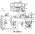
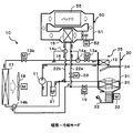
- FIG. 3 is a schematic diagram showing a refrigerant flow in a heating-non-temperature control mode of the refrigeration cycle apparatus of the first embodiment.
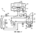
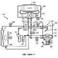
- FIG. 3 is a schematic diagram showing a refrigerant flow in a cooling-warming mode of the refrigeration cycle apparatus of the first embodiment.
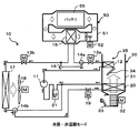
- FIG. 3 is a schematic diagram showing a refrigerant flow in a cooling / non-temperature control mode of the refrigeration cycle apparatus of the first embodiment.
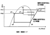
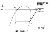
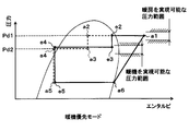
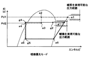
- FIG. 3 is a Mollier diagram showing the state of the refrigerant in the heating-warming-up mode of the refrigeration cycle apparatus of the first embodiment. It is a Mollier diagram which shows the state of the refrigerant
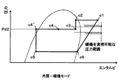
- FIG. 3 is a Mollier diagram showing the state of the refrigerant in the cooling-warming mode of the refrigeration cycle apparatus of the first embodiment.
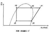
- FIG. 3 is a Mollier diagram showing the state of the refrigerant in the cooling-non-temperature control mode of the refrigeration cycle apparatus of the first embodiment. It is explanatory drawing for demonstrating the output characteristic of the battery (lithium ion battery) of 1st Embodiment.
- the refrigeration cycle apparatus 10 is applied to an electric vehicle that obtains driving force for vehicle travel from an electric motor for travel. Furthermore, in this electric vehicle, the refrigeration cycle apparatus 10 is provided with air conditioning (cooling and heating) in the passenger compartment, and temperature adjustment (warming up) of the battery 55 as a battery that stores electric power supplied to the electric motor for traveling. Used to do.
- the refrigeration cycle apparatus 10 fulfills the function of adjusting the temperature of the indoor air blown into the vehicle interior, which is the air-conditioning target space, and the function of heating the battery air blown toward the battery 55.
- the refrigeration cycle apparatus 10 can adjust the temperature of a plurality of temperature adjustment objects (temperature adjustment object fluid) such as room air and battery air.
- the refrigeration cycle apparatus 10 includes, as an air conditioning operation mode, a heating mode in which indoor air is heated to heat the vehicle interior and a cooling in which the indoor air is cooled to cool the vehicle interior. You can switch between modes. Furthermore, in the following description, an operation mode in which the temperature of the battery 55 is adjusted (warm-up) is expressed as a warm-up mode, and an operation state in which the temperature of the battery 55 is not adjusted is expressed as a non-temperature adjustment mode.
- the battery 55 of the present embodiment is a secondary battery that can repeatedly discharge electric power by being charged, and specifically employs a lithium ion battery.
- the output characteristics of the battery 55 will be described later.
- the compressor 11 is disposed in the vehicle bonnet, sucks the refrigerant in the refrigeration cycle apparatus 10, compresses it, and discharges it.
- a fixed capacity compressor with a fixed discharge capacity is driven to rotate by an electric motor. It is configured as an electric compressor.
- the operation (rotation speed) of the electric motor of the compressor 11 is controlled by a control signal output from the control device 100 described later.
- the refrigeration cycle apparatus 10 employs an HFC refrigerant (specifically, R134a) as the refrigerant, and constitutes a vapor compression subcritical refrigeration cycle in which the high-pressure side refrigerant pressure does not exceed the critical pressure of the refrigerant. is doing.
- an HFO refrigerant specifically, R1234yf
- the refrigerant is mixed with refrigerating machine oil for lubricating the compressor 11, and a part of the refrigerating machine oil circulates in the cycle together with the refrigerant.
- the refrigerant inlet side of the indoor condenser 12 is connected to the discharge port side of the compressor 11.
- the indoor condenser 12 is disposed in a casing 31 that forms an air passage for indoor air in an indoor air conditioning unit 30 to be described later, and after passing through a high-pressure refrigerant discharged from the compressor 11 and an indoor evaporator 20 to be described later. It is a heat exchanger for heating that heats indoor air by exchanging heat with indoor air.
- the indoor condenser 12 constitutes a heat exchanger that heats indoor air using the refrigerant discharged from the compressor 11 as a heat source.
- the details of the indoor air conditioning unit 30 will be described later.
- the inlet side of the high stage side expansion valve 13a is connected to the refrigerant outlet side of the indoor condenser 12 as a high stage side decompressor for decompressing the refrigerant flowing out of the indoor condenser 12.
- the high-stage expansion valve 13a is an electric variable throttle valve that includes a valve element that can change the opening degree and an electric actuator that includes a stepping motor that changes the opening degree of the valve element. The operation is controlled by a control signal output from the control device 100.
- the high stage side expansion valve 13a is constituted by a variable throttle valve with a fully open function that functions as a simple refrigerant passage without exhibiting almost a refrigerant pressure reducing action by fully opening the opening.
- a first three-way valve 14a is connected to the outlet side of the high stage side expansion valve 13a.
- the first three-way valve 14 a is an electric three-way valve whose operation is controlled by a control voltage output from the control device 100.
- the first three-way valve 14a includes a refrigerant circuit connecting the outlet side of the high stage side expansion valve 13a and the refrigerant inlet side of the battery heat exchanger 15, and the outlet of the high stage side expansion valve 13a.
- the refrigerant circuit that connects between the side and the inlet side of the bypass passage 16 is switched.
- the first three-way valve 14a constitutes a refrigerant circuit switching unit that switches the refrigerant circuit of the refrigerant circulating in the cycle.
- the battery heat exchanger 15 is disposed in the battery pack 50 that forms an air passage for battery air that is blown toward the battery 55, and exchanges heat between the refrigerant circulating in the battery pack and the battery air.
- the heat exchanger adjusts the temperature of the battery air.
- the battery 55 in the warm-up mode, the battery 55 is indirectly heated by exchanging heat between the refrigerant decompressed by the high stage side expansion valve 13a and the battery air and heating the battery air. .
- the battery heat exchanger 15 functions to heat the battery 55 via the battery air that is a heat medium, using the refrigerant decompressed by the high stage side expansion valve 13a as a heat source. Details of the battery pack 50 will be described later.
- the inlet side of the low stage side expansion valve 13 b is connected to the refrigerant outlet side of the battery heat exchanger 15.
- the bypass passage 16 is a refrigerant passage that guides the refrigerant flowing out from the high stage side expansion valve 13a to the inlet side of the low stage side expansion valve 13b by bypassing the battery heat exchanger 15.
- the low-stage side expansion valve 13b is a low-stage side pressure reducer that depressurizes the refrigerant that has flowed out of the battery heat exchanger 15, and its basic configuration is the same as that of the high-stage side expansion valve 13a. Therefore, the low stage side expansion valve 13b is configured by a variable throttle valve with a fully open function.
- the refrigerant inlet side of the outdoor heat exchanger 17 is connected to the outlet side of the low stage side expansion valve 13b.
- the outdoor heat exchanger 17 is arranged in the vehicle bonnet, and exchanges heat between the refrigerant flowing through the inside and the outside air blown from the blower fan 18. More specifically, the outdoor heat exchanger 17 of the present embodiment functions as an evaporator that evaporates the low-pressure refrigerant at least in the heating mode, and functions as a radiator that radiates heat to the high-pressure refrigerant at least in the cooling mode.
- the blower fan 18 is an electric blower in which the operation rate, that is, the rotation speed (the amount of air blown) is controlled by the control voltage output from the control device 100.
- a second three-way valve 14 b is connected to the refrigerant outlet side of the outdoor heat exchanger 17.
- the basic configuration of the second three-way valve 14b is the same as that of the first three-way valve 14a. Therefore, the second three-way valve 14b is an electric three-way valve whose operation is controlled by the control voltage output from the control device 100.
- the second three-way valve 14b is connected to the refrigerant circuit connecting the refrigerant outlet side of the outdoor heat exchanger 17 and the inlet side of the accumulator 21 disposed on the suction side of the compressor 11, and outdoor heat exchange.
- the refrigerant circuit connecting the refrigerant outlet side of the cooler 17 and the inlet side of the cooling expansion valve 19 is switched.
- the second three-way valve 14b constitutes a refrigerant circuit switching unit together with the first three-way valve 14a described above.
- the cooling expansion valve 19 is an electric expansion valve having the same configuration as the high stage side expansion valve 13a and the low stage side expansion valve 13b, and flows out from the outdoor heat exchanger 17 and flows into the indoor evaporator 20 in the cooling mode. It is the decompressor which decompresses the refrigerant
- the indoor evaporator 20 is disposed in the casing 31 of the indoor air conditioning unit 30 and on the upstream side of the air flow with respect to the indoor condenser 12 described above, and is decompressed by the cooling expansion valve 19 in the cooling mode. It is a cooling heat exchanger that cools indoor air by heat-exchanging low-pressure refrigerant and indoor air to evaporate.
- the inlet side of the accumulator 21 is connected to the refrigerant outlet side of the indoor evaporator 20.
- the accumulator 21 is a gas-liquid separator that separates the gas-liquid refrigerant flowing into the accumulator 21 and stores excess refrigerant in the cycle.
- the suction side of the compressor 11 is connected to the gas-phase refrigerant outlet of the accumulator 21. Therefore, the accumulator 21 functions to prevent liquid compression of the compressor 11 by suppressing the liquid phase refrigerant from being sucked into the compressor 11.
- the indoor air conditioning unit 30 is for blowing temperature-adjusted indoor air into the vehicle interior, and is a casing that is disposed inside the instrument panel (instrument panel) at the forefront of the vehicle interior and forms the outer shell thereof.
- a blower 32, the above-described indoor condenser 12, the indoor evaporator 20, the air mix door 34, and the like are accommodated in 31.
- the casing 31 has an air passage for indoor air formed therein, and is formed of a resin (for example, polypropylene) having a certain degree of elasticity and excellent strength.
- Inside / outside air switching device 33 for switching and introducing vehicle interior air (inside air) and outside air is arranged on the most upstream side of the air flow of the room air in casing 31.
- the inside / outside air switching device 33 is formed with an inside air introduction port for introducing inside air into the casing 31 and an outside air introduction port for introducing outside air. Furthermore, inside / outside air switching device 33 is provided with an inside / outside air switching door that continuously adjusts the opening area of the inside air introduction port and the outside air introduction port to change the air volume ratio between the inside air volume and the outside air volume. Has been.
- a blower 32 that blows air sucked through the inside / outside air switching device 33 toward the vehicle interior is disposed on the downstream side of the air flow of the inside / outside air switching device 33.
- the blower 32 is an electric blower that drives a centrifugal multiblade fan (sirocco fan) with an electric motor, and the number of rotations (air flow rate) is controlled by a control voltage output from the control device 100.
- the indoor evaporator 20 and the indoor condenser 12 are arranged in this order with respect to the flow of indoor air.
- the indoor evaporator 20 is disposed upstream of the indoor condenser 12 in the flow direction of the indoor air.
- the air volume ratio of the air that has passed through the indoor evaporator 20 is allowed to pass through the indoor condenser 12.
- An air mix door 34 to be adjusted is disposed.
- a mixing space in which air heated by exchanging heat with the refrigerant in the indoor condenser 12 and air that has not been heated bypassing the indoor condenser 12 are mixed. 35 is provided.
- the opening hole includes a face opening hole that blows air-conditioned air toward the upper body of the passenger in the passenger compartment, a foot opening hole that blows air-conditioned air toward the feet of the passenger, and an inner surface of the front window glass of the vehicle.
- a defroster opening hole (both not shown) for blowing the conditioned air toward is provided.
- face opening holes foot opening holes, and defroster opening holes are respectively provided on the downstream side of the air flow through ducts that form air passages, face outlets, foot outlets, and defroster outlets ( Neither is shown).
- the temperature of the conditioned air mixed in the mixing space 35 is adjusted by adjusting the ratio of the air volume that the air mix door 34 passes through the indoor condenser 12, and the temperature of the conditioned air blown out from each opening hole. Is adjusted. That is, the air mix door 34 constitutes a temperature adjustment unit that adjusts the temperature of the conditioned air blown into the vehicle interior.
- the air mix door 34 is driven by an electric actuator for driving the air mix door, and the operation of the electric actuator for driving the air mix door is controlled by a control signal output from the control device 100.
- a face door that adjusts the opening area of the face opening hole, a foot door that adjusts the opening area of the foot opening hole, and a defroster opening hole respectively A defroster door (none of which is shown) for adjusting the opening area is arranged.
- These face doors, foot doors, and defroster doors constitute a blower outlet mode switching unit that switches the blower outlet mode, and are linked to an electric actuator for driving the blower outlet mode door via a link mechanism or the like. And rotated.
- the operation of the electric actuator for driving the outlet mode door is also controlled by a control signal output from the control device 100.
- the outlet mode switched by the outlet mode switching unit specifically, a face mode in which the face outlet is fully opened and air is blown out from the face outlet toward the upper body of the passenger in the passenger compartment, the face outlet and the foot Bi-level mode that opens both air outlets and blows air toward the upper body and feet of passengers in the passenger compartment, opens the foot air outlet fully and opens the defroster air outlet only by a small opening, mainly from the foot air outlet
- a foot mode for blowing air a foot defroster mode for opening the foot blower outlet and the defroster blower outlet to the same extent, and blowing air from both the foot blower outlet and the defroster blower outlet.
- the battery pack 50 is disposed on the vehicle bottom side between the trunk room at the rear of the vehicle and the rear seat, and the battery air is placed in a metal casing 51 that has been subjected to electrical insulation processing (for example, insulation coating).
- electrical insulation processing for example, insulation coating
- An air passage for circulating air is formed, and the blower 52, the aforementioned battery heat exchanger 15, the battery 55, and the like are accommodated in the air passage.
- the blower 52 is disposed on the upstream side of the air flow of the battery heat exchanger 15 and blows the battery air toward the battery heat exchanger 15, and is operated by a control voltage output from the control device 100. That is, it is an electric blower in which the rotation speed (air amount) is controlled. Further, a battery 55 is arranged on the downstream side of the air flow of the battery heat exchanger 15, and the downstream side of the air flow of the battery 55 communicates with the suction port side of the blower 52.
- the blower 52 when the blower 52 is operated, the battery air whose temperature has been adjusted by the battery heat exchanger 15 is blown to the battery 55, and the temperature of the battery 55 is adjusted. Further, the battery air whose temperature has been adjusted for the battery 55 is sucked into the blower 52 and blown again toward the battery heat exchanger 15.
- the control device 100 is composed of a well-known microcomputer including a CPU, ROM, RAM, etc. and its peripheral circuits, and performs various calculations and processing based on a control program stored in the ROM, and is connected to the output side. It controls the operation of various control target devices 11, 13a, 13b, 14a, 14b, 18, 19, 32, 52.
- an inside air sensor that detects the vehicle interior temperature (inside air temperature) Tr, an outside air sensor that detects the vehicle interior outside temperature (outside air temperature) Tam, and the amount of solar radiation As irradiated to the vehicle interior are detected.
- a solar radiation sensor that detects the refrigerant pressure (high-pressure side refrigerant pressure) Pd1 of the refrigerant on the outlet side of the indoor condenser 12 and a refrigerant temperature (high-pressure side refrigerant temperature) Td1 of the refrigerant on the outlet side of the indoor condenser 12
- High pressure side refrigerant temperature sensor for detecting the refrigerant pressure (intermediate pressure side refrigerant pressure) Pd2 of the refrigerant on the outlet side of the battery heat exchanger 15, and refrigerant temperature of the refrigerant on the outlet side of the battery heat exchanger 15 (intermediate pressure side refrigerant)
- An intermediate pressure side refrigerant temperature sensor for detecting (temperature) Td2 is connected.
- an evaporator temperature sensor for detecting the refrigerant evaporation temperature (evaporator temperature) Tefin in the indoor evaporator 20, an air temperature sensor for detecting the air temperature TAV blown from the mixing space into the vehicle compartment, and an outdoor heat exchanger.
- the outdoor heat exchanger temperature sensor that detects the outdoor unit temperature Ts of the outdoor heat exchanger 17, the outdoor heat exchanger pressure sensor that detects the refrigerant pressure Ps of the refrigerant on the outlet side of the outdoor heat exchanger 17, and the battery temperature Tb that is the temperature of the battery 55 are detected.
- Various control sensor groups such as a battery temperature sensor as a temperature detector are connected.
- the evaporator temperature sensor of this embodiment has detected the heat exchange fin temperature of the indoor evaporator 20, the temperature detector which detects the temperature of the other site
- the outdoor heat exchanger temperature sensor of this embodiment has detected the temperature of the refrigerant
- an air temperature sensor for detecting the air temperature TAV is provided.
- a value calculated based on the evaporator temperature Tefin, the discharge refrigerant temperature Td, or the like is adopted as the air temperature TAV, Good.
- a battery temperature sensor is configured by a plurality of temperature detectors that detect temperatures at a plurality of locations on the inside and on the surface of the battery 55, and the average value of the detection values of the plurality of temperature detectors is determined as the battery.
- the temperature is Tb.
- an operation panel (not shown) arranged near the instrument panel in the front part of the vehicle interior is connected, and operation signals from various operation switches provided on the operation panel are input.
- an air conditioning operation switch that requires air conditioning in the vehicle interior
- a vehicle interior temperature setting switch as a target temperature setting unit that sets a target temperature Tset in the vehicle interior
- an air conditioning operation A mode selection switch and the like are provided.
- control device 100 of the present embodiment is configured such that a control unit that controls various control target devices connected to the output side thereof is integrally configured, but the configuration that controls the operation of each control target device. (Hardware and Software) constitutes a control unit that controls the operation of each control target device.
- a configuration (hardware and software) for controlling the operation (refrigerant discharge capability) of the compressor 11 constitutes a discharge capability control unit, and a configuration for controlling the operation of the high stage side expansion valve 13a.
- operation of the low stage side expansion valve 13b comprises the low stage side opening degree control part.
- operation of 1st, 2nd three-way valve 14a, 14b etc. comprises a refrigerant circuit switching control part
- the structure which controls the ventilation capacity of the air blower 32 comprises the ventilation capacity control part. .
- the refrigeration cycle apparatus 10 of the present embodiment having the above configuration will be described.
- the refrigeration cycle apparatus 10 there are a heating mode and a cooling mode as air-conditioning operation modes, and a warm-up mode and a non-temperature adjustment mode as warm-up operation modes of the battery 55.
- the switching of these operation modes is performed by the control device 100 executing a control program stored in advance in the storage circuit.
- the operation signal of the operation panel and the detection signal of the control sensor group are read, the control state of various control target devices is determined based on the read detection signal and the value of the operation signal, and the determined control state
- the control routine of outputting a control signal (control voltage) to various control target devices is repeated so that
- the air conditioning operation mode when the operation signal is read from the operation panel and the air conditioning operation switch is turned on (ON) and the heating is selected by the selection switch, the heating mode is selected.
- the air conditioning operation switch is turned on (ON) and cooling is selected by the selection switch, it is switched to the cooling mode.
- the battery temperature Tb is equal to or lower than the first reference temperature Tk1 (15 ° C. in the present embodiment). Is operated in the warm-up mode, and when the battery temperature Tb is equal to or higher than the second reference temperature Tk2 (30 ° C. in the present embodiment), the operation in the warm-up mode is stopped. That is, the mode is switched to the non-temperature control mode.
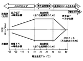
- the output characteristics of the battery 55 (lithium ion battery) of the present embodiment will be described with reference to FIG.
- the battery 55 of the present embodiment as shown in FIG. 9, when the temperature becomes 10 ° C. or lower, sufficient input / output characteristics cannot be obtained because the chemical reaction does not proceed. That is, if the battery 55 becomes 10 degrees C or less, the output of the battery 55 will fall and it will become impossible to drive a vehicle.
- the battery temperature Tb is equal to or lower than the first reference temperature Tk1, with the temperature range (10-40 ° C.) determined so that the capacity of the battery 55 can be fully utilized as the reference temperature range.
- the battery temperature Tb is equal to or higher than the second reference temperature Tk2
- the battery temperature Tb is within the reference temperature range by switching to the non-temperature control mode. .
- the heating-warm-up mode is an operation mode in which the heating mode and the warm-up mode are executed simultaneously. More specifically, in this operation mode, when the operation switch of the operation panel is turned on (ON), heating is selected by the selection switch, and the battery temperature Tb is equal to or lower than the first reference temperature Tk1. Executed.
- the control device 100 puts the high-stage expansion valve 13a and the low-stage expansion valve 13b into a throttled state that exerts a pressure reducing action, and fully closes the cooling expansion valve 19. Further, the operation of the first three-way valve 14a is controlled so as to connect the outlet side of the high stage side expansion valve 13a and the refrigerant inlet side of the battery heat exchanger 15, and the refrigerant outlet side of the outdoor heat exchanger 17 is controlled. And the operation of the second three-way valve 14b are controlled so as to connect the inlet side of the accumulator 21.
- the refrigeration cycle apparatus 10 is switched to the refrigerant circuit through which the refrigerant flows as shown by the solid line arrow in FIG. 1A.
- the control device 100 sets a target air temperature TAO, which is a target temperature of air blown into the vehicle interior, based on the read detection signal and operation signal values based on the following formula F1.
- TAO Kset ⁇ Tset ⁇ Kr ⁇ Tr ⁇ Kam ⁇ Tam ⁇ Ks ⁇ As + C (F1)
- Tr is the vehicle interior set temperature set by the temperature setting switch
- Tr is the vehicle interior temperature (inside air temperature) detected by the inside air sensor
- Tam is the outside air temperature detected by the outside air sensor
- As is detected by the solar radiation sensor.
- Kset, Kr, Kam, Ks are control gains
- C is a correction constant.
- the control step for determining the target air temperature TAO in the control program executed by the control device 100 constitutes the target temperature determination unit 100a. Furthermore, the control device 100 determines the operating states of various control target devices connected to the output side of the control device 100 based on the calculated target air temperature TAO and the detection signal of the sensor group.
- the refrigerant discharge capacity of the compressor 11, that is, the control signal output to the electric motor of the compressor 11, is stored in the control device 100 in advance based on the target air temperature TAO.
- the target high pressure Pdt1 in the indoor condenser 12 is determined with reference to FIG.
- a control signal output to the electric motor of the compressor 11 is determined so that the high-pressure side refrigerant pressure Pd1 detected by the high-pressure side refrigerant pressure sensor approaches the target high-pressure Pdt1.
- the target high pressure Pdt1 is a value determined so that the air temperature TAV detected by the air temperature sensor approaches the target air temperature TAO.
- the refrigerant discharge capacity of the compressor 11 is controlled such that the air temperature TAV approaches the target air temperature TAO.
- the target air temperature TAO determined at the time of heating the passenger compartment is about 40-60 ° C.
- the opening degree of the high stage side expansion valve 13a is determined so that the intermediate pressure side refrigerant pressure Pd2 detected by the intermediate pressure side refrigerant pressure sensor approaches the target intermediate pressure Pdt2.
- the target intermediate pressure Pdt2 is a value determined so that the temperature of the battery 55 is within the above-described reference temperature range (10-40 ° C.).
- the opening degree of the high stage side expansion valve 13a is controlled so that the temperature of the battery 55 is within the reference temperature range.
- the subcooling of the refrigerant on the outlet side of the battery heat exchanger 15 is calculated based on the intermediate pressure side refrigerant pressure Pd2 and the intermediate pressure side refrigerant temperature Td2 detected by the intermediate pressure side refrigerant temperature sensor.
- the degree is determined so as to approach the target supercooling degree KSC (5K-15K in the present embodiment) determined so that the coefficient of performance (COP) of the cycle becomes substantially the maximum value.
- the control voltage output to the electric motor of the blower 32 is determined based on the target air temperature TAO with reference to a control map stored in advance in the storage circuit. Specifically, in the extremely low temperature region (maximum cooling region) and the extremely high temperature region (maximum heating region) of the target air temperature TAO, the control voltage output to the electric motor is controlled to the maximum, and the amount of air to be blown is controlled near the maximum amount. The air amount is decreased as the target air temperature TAO approaches the intermediate temperature range.
- the control signal output to the electric actuator of the air mix door 34 is determined so that the air mix door 34 fully opens the air passage on the indoor condenser 12 side.
- the control signal output to the air blower 52 of the battery pack 50 it determines so that the air blowing capability of the air blower 52 may become predetermined predetermined air blowing capability.
- a control signal (control voltage) is output from the control device 100 to the control target device so as to obtain the control state determined as described above.
- the state of the refrigerant changes as shown in the Mollier diagram of FIG. That is, the high-pressure refrigerant discharged from the compressor 11 flows into the indoor condenser 12 and dissipates heat by exchanging heat with indoor air (from point a1 to point a2 in FIG. 5). Thereby, room air is heated and heating of the vehicle interior is realized.
- the refrigerant pressure in the indoor condenser 12 (corresponding to the high-pressure side refrigerant pressure Pd1) is adjusted to a value at which the air temperature TAV can achieve heating in the vehicle interior, as described above.
- the refrigerant that has flowed out of the indoor condenser 12 is depressurized by the high-stage expansion valve 13a until it reaches an intermediate pressure (from point a2 to point a3 in FIG. 5).
- the refrigerant decompressed by the high stage side expansion valve 13a flows into the battery heat exchanger 15 through the first three-way valve 14a.
- the refrigerant flowing into the battery heat exchanger 15 exchanges heat with the battery air and dissipates heat (from point a3 to point a4 in FIG. 5).
- the refrigerant pressure in the battery heat exchanger 15 (corresponding to the intermediate pressure refrigerant pressure Pd2) is adjusted to a pressure at which the battery temperature Tb is within the reference temperature range.
- the refrigerant that has flowed out of the battery heat exchanger 15 is depressurized by the low-stage expansion valve 13b until it becomes low pressure (points a4 to a5 in FIG. 5). At this time, the degree of supercooling (a4 in FIG. 5) of the refrigerant on the outlet side of the battery heat exchanger 15 is adjusted so as to approach the target degree of supercooling KSC. Thereby, the refrigeration cycle apparatus 10 can exhibit a high COP.
- the low-pressure refrigerant decompressed by the low-stage expansion valve 13b flows into the outdoor heat exchanger 17, absorbs heat from the outside air blown from the blower fan 18, and evaporates (points a5 to a6 in FIG. 5).
- the refrigerant that has flowed out of the outdoor heat exchanger 17 flows into the accumulator 21 via the second three-way valve 14b. Then, the gas-phase refrigerant separated by the accumulator 21 is sucked into the compressor 11 and compressed again.
- the indoor air can be heated by the indoor condenser 12 to heat the vehicle interior, and the battery air is heated by the battery heat exchanger 15 to thereby charge the battery 55. Can be warmed up.
- the heating-non-temperature control mode is an operation mode in which the passenger compartment is air-conditioned in the heating mode and the battery 55 is not heated (warmed up). More specifically, in this operation mode, when the operation switch of the operation panel is turned on (ON), heating is selected by the selection switch, and the battery temperature Tb is higher than the second reference temperature Tk2. To be executed.
- the control device 100 sets the high stage side expansion valve 13a to the throttle state, fully opens the low stage side expansion valve 13b, and fully closes the cooling expansion valve 19. Further, the operation of the first three-way valve 14a is controlled so as to connect between the outlet side of the high stage side expansion valve 13a and the inlet side of the bypass passage 16, and the refrigerant outlet side of the outdoor heat exchanger 17 and the inlet of the accumulator 21 are controlled. The operation of the second three-way valve 14b is controlled so as to connect the two sides.
- the refrigeration cycle apparatus 10 is switched to the refrigerant circuit through which the refrigerant flows as shown by the solid line arrow in FIG.
- the control device 100 calculates the target air temperature TAO in the same manner as in the heating-warm-up mode, and performs various controls based on the calculated target air temperature TAO and the sensor group detection signal. Determine the operating state of the target device.
- the opening degree of the high stage side expansion valve 13a is calculated based on the high pressure side refrigerant pressure Pd1 detected by the high pressure side refrigerant pressure sensor and the high pressure side refrigerant temperature Td1 detected by the high pressure side refrigerant temperature sensor.
- the degree of supercooling of the condenser 12 outlet side refrigerant is determined so as to approach the target degree of supercooling KSC. Thereby, the refrigerant decompressed by the high stage side expansion valve 13a becomes a low-pressure refrigerant whose saturation temperature is lower than the outside air temperature.
- the outlet side of the bypass passage 16 of the refrigeration cycle apparatus 10 of the present embodiment communicates with the battery heat exchanger 15, so that the battery in the heating-non-temperature control mode is used.
- the refrigerant pressure in the industrial heat exchanger 15 is equivalent to the low-pressure refrigerant. That is, in the heating / non-temperature control mode, the opening degree of the high stage side expansion valve 13a is controlled such that the saturation temperature of the refrigerant in the battery heat exchanger 15 is lower than the outside air temperature.
- Other devices to be controlled are controlled in the same manner as in the heating-warm-up mode.
- the state of the refrigerant changes as shown in the Mollier diagram of FIG. That is, the high-pressure refrigerant discharged from the compressor 11 flows into the indoor condenser 12 as in the heating-warm-up mode, and dissipates heat by exchanging heat with indoor air (from point b1 to point b2 in FIG. 6). Thereby, room air is heated and heating of the vehicle interior is realized.
- the refrigerant that has flowed out of the indoor condenser 12 is depressurized by the high stage side expansion valve 13a until it becomes low pressure (b2 point to b5 point in FIG. 6).
- the degree of supercooling (b2 in FIG. 6) of the refrigerant on the outlet side of the indoor condenser 12 is adjusted so as to approach the target degree of supercooling KSC.
- the refrigeration cycle apparatus 10 can exhibit a high COP.
- the low-pressure refrigerant decompressed by the high-stage expansion valve 13a flows in the order of the first three-way valve 14a, the bypass passage 16, the low-stage expansion valve 13b, and the outdoor heat exchanger 17.
- the refrigerant flowing into the low stage side expansion valve 13b flows into the outdoor heat exchanger 17 without being decompressed.
- the refrigerant flowing into the outdoor heat exchanger 17 absorbs heat from the outside air blown from the blower fan 18 and evaporates (points b5 to b6 in FIG. 6).
- the subsequent operation is the same as in the heating-warm-up mode.
- the indoor air is heated by the indoor condenser 12 and the vehicle interior can be heated. Further, the battery air is not heated by the battery heat exchanger 15, and the battery 55 is not warmed up.
- the cooling-warm-up mode is an operation mode in which the cooling mode and the warm-up mode are executed simultaneously. More specifically, this operation mode is executed when the operation switch of the operation panel is turned on (ON), cooling is selected by the selection switch, and the battery temperature Tb becomes equal to or lower than the first reference temperature Tk1. Is done.
- the control device 100 sets the high stage side expansion valve 13a and the cooling expansion valve 19 to the throttle state, and fully opens the low stage side expansion valve 13b. Further, the operation of the first three-way valve 14a is controlled so as to connect the outlet side of the high stage side expansion valve 13a and the refrigerant inlet side of the battery heat exchanger 15, and the refrigerant outlet side of the outdoor heat exchanger 17 is controlled. The operation of the second three-way valve 14b is controlled so as to connect between the inlet and the inlet side of the cooling expansion valve 19.
- the refrigeration cycle apparatus 10 is switched to the refrigerant circuit through which the refrigerant flows as shown by the solid line arrow in FIG.
- the control device 100 calculates the target air temperature TAO in the same manner as in the heating-warm-up mode and the like, and based on the calculated target air temperature TAO and the detection signal of the sensor group, Determine the operating state of the controlled device.
- the refrigerant discharge capacity of the compressor 11, that is, the control signal output to the electric motor of the compressor 11 is determined as follows. First, the target evaporator air temperature TEO of the indoor evaporator 20 is determined based on the target air temperature TAO with reference to a control map stored in the control device 100 in advance.
- the control signal output to the electric motor of the compressor 11 is determined.
- the opening degree of the cooling expansion valve 19 is calculated based on the outdoor unit temperature Ts detected by the outdoor heat exchanger temperature sensor and the outlet side refrigerant pressure Ps detected by the outdoor heat exchanger pressure sensor.
- the degree of supercooling of the refrigerant on the outlet side of the outdoor heat exchanger 17 is determined so as to approach the target degree of supercooling KSC.
- the control signal output to the servo motor of the air mix door 34 is determined so that the air temperature TAV approaches the target air temperature TAO.
- the air mix door 34 may be operated so that the air mix door 34 closes the air passage on the indoor condenser 12 side.
- the control of other various devices to be controlled is the same as in the heating-warm-up mode.
- the state of the refrigerant changes as shown in the Mollier diagram of FIG. That is, the high-pressure refrigerant discharged from the compressor 11 flows into the indoor condenser 12 and dissipates heat by exchanging heat with indoor air (from point c1 to point c2 in FIG. 7). Thereby, a part of room air is heated.
- the refrigerant that has flowed out of the indoor condenser 12 is depressurized by the high stage side expansion valve 13a until it reaches an intermediate pressure (from the point c2 to the point c3 in FIG. 7) in the same manner as in the heating-warm-up mode. 15 flows into.
- the refrigerant flowing into the battery heat exchanger 15 exchanges heat with the battery air and dissipates heat (from point c3 to point c4 in FIG. 7). As a result, the battery air is heated and the battery 55 is warmed up.
- the refrigerant that has flowed out of the battery heat exchanger 15 flows into the outdoor heat exchanger 17 without being depressurized by the low-stage expansion valve 13b because the low-stage expansion valve 13b is fully open.
- the refrigerant that has flowed into the outdoor heat exchanger 17 exchanges heat with the outside air blown from the blower fan 18 to further dissipate and reduce enthalpy (from point c4 to point c4 'in FIG. 7).
- the refrigerant that has flowed out of the outdoor heat exchanger 17 flows into the cooling expansion valve 19 via the second three-way valve 14b, and is reduced in pressure until it becomes low pressure (from point c4 'to point c5 in FIG. 7).
- the degree of supercooling (point c4 ′ in FIG. 7) of the refrigerant on the outlet side of the outdoor heat exchanger 17 is adjusted so as to approach the target degree of supercooling KSC.
- the refrigeration cycle apparatus 10 can exhibit a high COP.
- the low-pressure refrigerant decompressed by the cooling expansion valve 19 flows into the indoor evaporator 20 and absorbs heat from the indoor air blown from the blower 32 to evaporate (points c5 to c6 in FIG. 7). Thereby, indoor air is cooled. Then, a part of the indoor air cooled by the indoor evaporator 20 is reheated by the indoor condenser 12 so that the indoor air is adjusted so as to approach the target air temperature TAO, thereby cooling the vehicle interior. Is realized.
- the refrigerant that has flowed out of the indoor evaporator 20 flows into the accumulator 21. Then, the gas-phase refrigerant separated by the accumulator 21 is sucked into the compressor 11 and compressed again.
- the indoor air can be cooled by the indoor evaporator 20 to cool the vehicle interior, and the battery air can be heated by the battery heat exchanger 15 and the battery 55 can be cooled. Can be warmed up.
- the cooling / non-temperature control mode is an operation mode in which the vehicle interior air conditioning is performed in the cooling mode and the battery 55 is not heated (warmed up). More specifically, in this operation mode, when the operation switch of the operation panel is turned on (ON), cooling is selected by the selection switch, and the battery temperature Tb is higher than the second reference temperature Tk2. To be executed.
- the control device 100 In the cooling / non-temperature control mode, the control device 100 fully opens the high stage side expansion valve 13a and the low stage side expansion valve 13b, and sets the cooling expansion valve 19 to the throttle state. Further, the operation of the first three-way valve 14a is controlled so as to connect the outlet side of the high stage side expansion valve 13a and the inlet side of the bypass passage 16, and the refrigerant outlet side of the outdoor heat exchanger 17 and the cooling expansion valve are controlled. The operation of the second three-way valve 14b is controlled so as to connect to the 19 inlet side.
- the refrigeration cycle apparatus 10 is switched to the refrigerant circuit through which the refrigerant flows as shown by the solid line arrow in FIG.
- the control device 100 calculates the target air temperature TAO in the same manner as in the cooling-warm-up mode, and based on the calculated target air temperature TAO and the detection signal of the sensor group, Similarly to the warm-up mode, the operating states of various control target devices are determined.
- the state of the refrigerant changes as shown in the Mollier diagram of FIG. That is, the high-pressure refrigerant discharged from the compressor 11 flows into the indoor condenser 12 and exchanges heat with indoor air in the same manner as in the cooling / warming mode, and dissipates heat (points d1 to d2 in FIG. 8). . Thereby, a part of room air is heated.
- the refrigerant flowing out of the indoor condenser 12 flows in the order of the high-stage side expansion valve 13a, the first three-way valve 14a, the bypass passage 16, and the low-stage side expansion valve 13b, and flows into the outdoor heat exchanger 17.
- the refrigerant that has flowed out of the indoor condenser 12 flows into the high stage side expansion valve 13a and the low stage side expansion valve 13b. It flows into the outdoor heat exchanger 17 without being depressurized by the stage side expansion valve 13b.
- the refrigerant flowing into the outdoor heat exchanger 17 exchanges heat with the outside air blown from the blower fan 18 to further dissipate and reduce enthalpy (from point d2 to point d4 in FIG. 8).
- the refrigerant that has flowed out of the outdoor heat exchanger 17 flows into the cooling expansion valve 19 through the second three-way valve 14b, and is reduced in pressure until it becomes low pressure (from point d4 to point d5 in FIG. 8).
- the degree of supercooling (point d4 in FIG. 8) of the refrigerant on the outlet side of the outdoor heat exchanger 17 is adjusted so as to approach the target degree of supercooling KSC. Thereby, the refrigeration cycle apparatus 10 can exhibit a high COP.
- the low-pressure refrigerant depressurized by the cooling expansion valve 19 flows into the indoor evaporator 20, absorbs heat from the indoor air blown from the blower 32, and evaporates (points d5 to d6 in FIG. 8). As a result, the indoor air is cooled, and the vehicle interior is cooled in the same manner as in the cooling-warm-up mode. The subsequent operation is the same as in the cooling-warming-up mode.
- the indoor air is cooled by the indoor evaporator 20 so that the vehicle interior can be cooled. Further, the battery air is not heated by the battery heat exchanger 15, and the battery 55 is not warmed up.
- indoor air can be heated by the indoor condenser 12 when heating the vehicle interior, and when cooling the vehicle interior.
- the indoor evaporator 20 can cool the indoor air.
- the battery 55 when the battery 55 is warmed up, the battery 55 can be indirectly heated by heating the battery air in the battery heat exchanger 15.
- thermo adjustment object fluid such as indoor air and battery air.
- the indoor air is heated using the high-pressure refrigerant discharged from the compressor 11 as a heat source, and the battery air is heated using the intermediate-pressure refrigerant decompressed by the high stage side expansion valve 13a. Therefore, the temperature of the battery air can be adjusted in a temperature range lower than the temperature of the room air.
- the temperature of the refrigerant radiated by the battery heat exchanger 15 can be easily adjusted by adjusting the opening degree of the high-stage side expansion valve 13a. Therefore, the temperature of the battery air can be easily adjusted. can do. As a result, the battery temperature Tb can be adjusted within the reference temperature range very easily, and the capacity of the battery 55 can be fully utilized.
- the accumulator 21 is provided, so that the liquid compression of the compressor 11 is unlikely to occur.
- the temperature of the indoor air heated by the indoor condenser 12 is adjusted by adjusting the refrigerant discharge capacity of the compressor 11 in the heating-warm-up mode.
- the temperature of the battery air heated by the battery heat exchanger 15 is adjusted by adjusting the opening degree of the stage side expansion valve 13a. Therefore, the battery temperature Tb can be adjusted without being affected by the temperature adjustment of the room air.
- the high-stage expansion valve 13a in the heating-non-temperature control mode, the high-stage expansion valve 13a is in the throttled state and the low-stage expansion valve 13b is fully opened, so that the battery heat exchanger 15
- the saturation temperature of the refrigerant inside is made lower than the outside air temperature.
- the refrigerant in the battery heat exchanger 15 can be evaporated, and it is possible to suppress the liquid-phase refrigerant from being accumulated in the battery heat exchanger 15 and being unable to flow out.
- this ensures that the battery temperature Tb is maintained within the reference temperature range, so that the cycle is cycled even when the switching frequency between the heating-warm-up mode and the heating-non-temperature control mode is increased.
- This is effective in that the flow rate of circulating refrigerant can be largely prevented from fluctuating. Therefore, the accumulator 21 can be downsized and the refrigeration cycle apparatus 10 as a whole can be downsized.
- the high-stage expansion valve 13a is fully opened and the low-stage expansion valve 13b is in the throttled state, so that the inside of the battery heat exchanger 15 is
- the saturation temperature of the refrigerant becomes higher than the outside air temperature
- the refrigeration cycle apparatus applied to a general vehicle air conditioner about 300 cc of liquid phase refrigerant is connected to the battery heat exchanger 15 and the pipe connected thereto. It has been found that it stays inside.
- the density of the high-pressure gas-phase refrigerant is 70 g / L
- the density of the high-pressure liquid-phase refrigerant is 1000 g / L
- the density of the low-pressure gas-liquid two-phase refrigerant is 30 g / L.
- L means liters.
- the refrigerant temperature in the battery heat exchanger 15 is not adjusted to be lower than the outside air temperature in the cooling / non-temperature control mode, but the fluctuation of the circulating refrigerant flow due to this is hardly affected. .
- the reason for this is that, as described above, the operation in the cooling-warm-up mode is rarely performed, and when the cooling-warm-up mode is switched to the cooling-non-temperature control mode, the battery heat exchanger 15 is not liquidated. This is because the phase refrigerant is difficult to accumulate.
- the refrigeration cycle apparatus 10 of the present embodiment includes the bypass passage 16, the refrigerant does not flow through the battery heat exchanger 15 during the heating-non-temperature adjustment mode and the cooling-non-temperature adjustment mode. Therefore, even in the non-temperature adjustment mode, the temperature distribution of the battery 55 can be suppressed by operating the blower 52 of the battery pack 50.
- the refrigerating cycle apparatus comprised so that switching between the warming-up mode which warms up the battery 55, and the non-temperature control mode which does not warm up the battery 55 was demonstrated, in this embodiment, Further, the refrigeration cycle apparatus 10 capable of operating in a cooling mode for cooling the battery 55 will be described.
- FIGS. 10 and 11 the same or equivalent parts as those in the first embodiment are denoted by the same reference numerals. The same applies to the following drawings.
- the refrigerant flow in the heating-cooling mode and the cooling-cooling mode is indicated by solid arrows.
- the inlet side of the cooling expansion valve 19 and the refrigerant inlet side of the battery heat exchanger 15 are different from those of the first embodiment.
- a first connection passage 22a to be connected and a second connection passage 22b to connect the refrigerant outlet side of the battery heat exchanger 15 and the inlet side of the accumulator 21 are provided.
- a cooling expansion valve 23 is disposed in the first connection passage 22a to depressurize the refrigerant flowing into the battery heat exchanger 15 in the cooling mode.
- the basic configuration of the cooling expansion valve 23 is the same as that of the cooling expansion valve 19.
- a third three-way valve 14c as a refrigerant circuit switching unit is disposed in the second connection passage 22b.
- the third three-way valve 14c is an electric three-way valve having the same configuration as the first and second three-way valves 14a and 14b.
- the third three-way valve 14c includes a refrigerant circuit that connects between the refrigerant outlet side of the battery heat exchanger 15 and the inlet side of the low-stage expansion valve 13b, and the refrigerant of the battery heat exchanger 15.
- the refrigerant circuit that connects the outlet side and the inlet side of the accumulator 21 is switched.
- Other configurations of the refrigeration cycle apparatus 10, the indoor air conditioning unit 30, and the battery pack 50 are the same as those in the first embodiment.
- the operation of the refrigeration cycle apparatus 10 of the present embodiment having the above configuration will be described.
- the refrigeration cycle apparatus 10 there are a heating mode and a cooling mode as the operation mode for air conditioning, and the cooling of the battery 55 is performed as the operation mode for warming up the battery 55 in addition to the warm-up mode and the non-temperature control mode.
- the cooling mode for cooling the battery 55 is executed when the battery temperature Tb is equal to or higher than the third reference temperature Tk3 (35 ° C. in the present embodiment), and the battery temperature Tb is the reference.
- the temperature is within the range.
- the switching of other operation modes is the same as in the first embodiment.
- control device 100 causes the high-stage side expansion valve 13a and the low-stage side expansion valve 13b to be in the throttle state, and fully closes the cooling expansion valve 19 and the cooling expansion valve 23.
- the operation of the first three-way valve 14a is controlled so as to connect between the outlet side of the high stage side expansion valve 13a and the refrigerant inlet side of the battery heat exchanger 15, and the refrigerant inlet of the battery heat exchanger 15 is controlled.
- the operation of the third three-way valve 14c is controlled so as to connect the inlet side of the low-stage expansion valve 13b and the refrigerant outlet side of the outdoor heat exchanger 17 and the inlet side of the accumulator 21 are connected.
- the operation of the second three-way valve 14b is controlled.
- a refrigerant circuit similar to the heating-warming-up mode of the first embodiment is configured. Furthermore, the control of other devices to be controlled is the same as in the heating-warm-up mode of the first embodiment. Accordingly, the heating of the passenger compartment and the warming up of the battery 55 can be realized in exactly the same manner as in the heating-warming-up mode of the first embodiment.
- the control device 100 sets the high stage expansion valve 13a to the throttle state, fully opens the low stage side expansion valve 13b, and fully closes the cooling expansion valve 19 and the cooling expansion valve 23. .
- the operation of the first three-way valve 14a is controlled so as to connect the outlet side of the high stage side expansion valve 13a and the inlet side of the bypass passage 16, and the refrigerant outlet side and the low stage side of the battery heat exchanger 15 are controlled.
- the operation of the third three-way valve 14c is controlled so as to connect the inlet side of the expansion valve 13b, and the second so as to connect the refrigerant outlet side of the outdoor heat exchanger 17 and the inlet side of the accumulator 21.
- the operation of the three-way valve 14b is controlled.
- a refrigerant circuit similar to the heating-non-temperature control mode of the first embodiment is configured. Further, the control of other devices to be controlled is the same as in the heating-non-temperature adjustment mode of the first embodiment. Therefore, the heating of the passenger compartment can be realized just like the heating-non-temperature control mode of the first embodiment.
- the heating-cooling mode is an operation mode in which the passenger compartment is air-conditioned in the heating mode and the battery 55 is cooled. More specifically, in this operation mode, when the operation switch of the operation panel is turned on (ON), heating is selected by the selection switch, and the battery temperature Tb is higher than the third reference temperature Tk3. To be executed.
- the control device 100 places the cooling expansion valve 23 in the throttle state, fully opens the high stage side expansion valve 13a and the low stage side expansion valve 13b, and fully closes the cooling expansion valve 19.
- the operation of the first three-way valve 14a is controlled so as to connect the outlet side of the high stage side expansion valve 13a and the inlet side of the bypass passage 16, and the refrigerant outlet side of the battery heat exchanger 15 and the accumulator 21 are controlled.
- the operation of the third three-way valve 14c is controlled so as to connect between the inlet side and the second three-way so as to connect between the refrigerant outlet side of the outdoor heat exchanger 17 and the inlet side of the cooling expansion valve 19.
- the operation of the valve 14b is controlled.
- the refrigeration cycle apparatus 10 is switched to the refrigerant circuit through which the refrigerant flows as shown by the solid line arrows in FIG.
- the control device 100 calculates the target air temperature TAO in the same manner as in the heating-warm-up mode, and performs various controls based on the calculated target air temperature TAO and the sensor group detection signal. Determine the operating state of the target device.
- the degree of supercooling of the refrigerant on the outlet side of the outdoor heat exchanger 17 calculated based on the outdoor unit temperature Ts and the refrigerant pressure Ps on the outlet side of the outdoor heat exchanger 17 is the target excess.
- the degree of cooling is determined to approach KSC.
- Other devices to be controlled are controlled in the same manner as in the heating-warm-up mode.
- the high-pressure refrigerant discharged from the compressor 11 flows into the indoor condenser 12 as in the heating-warm-up mode, and exchanges heat with indoor air to dissipate heat. .
- room air is heated and heating of the vehicle interior is realized.
- the refrigerant flowing out of the indoor condenser 12 flows in the order of the high stage side expansion valve 13a, the first three-way valve 14a, the bypass passage 16, and the low stage side expansion valve 13b and flows into the outdoor heat exchanger 17.
- the high stage side expansion valve 13a and the low stage side expansion valve 13b are fully opened, so that the refrigerant flowing out of the indoor condenser 12 flows into the outdoor heat exchanger 17 without being depressurized. To do.
- the refrigerant that has flowed into the outdoor heat exchanger 17 exchanges heat with the outside air blown from the blower fan 18 to further dissipate heat, thereby reducing enthalpy.
- the refrigerant flowing out of the outdoor heat exchanger 17 flows into the cooling expansion valve 23 through the second three-way valve 14b and the first connection passage 22a, and is decompressed until it becomes a low pressure, and flows into the battery heat exchanger 15. To do. At this time, the degree of supercooling of the refrigerant on the outlet side of the outdoor heat exchanger 17 is adjusted so as to approach the target degree of supercooling KSC. Thereby, the refrigeration cycle apparatus 10 can exhibit a high COP.
- the low-pressure refrigerant decompressed by the cooling expansion valve 23 flows into the battery heat exchanger 15, absorbs heat from the battery air blown from the blower 52 of the battery pack 50, and evaporates. Thereby, the battery air is cooled. The cooled battery air is blown onto the battery 55 by the blower 52, whereby the battery 55 is cooled.
- the refrigerant that has flowed out of the battery heat exchanger 15 flows into the accumulator 21 through the third three-way valve 14c and the second connection passage 22b. Then, the gas-phase refrigerant separated by the accumulator 21 is sucked into the compressor 11 and compressed again.
- the indoor air can be heated by the indoor condenser 12 to heat the vehicle interior, and the battery air is cooled by the battery heat exchanger 15 to Cooling can be performed.
- control device 100 brings the high stage expansion valve 13a and the cooling expansion valve 19 into the throttle state, fully opens the low stage side expansion valve 13b, and fully closes the cooling expansion valve 23.
- the operation of the first three-way valve 14a is controlled so as to connect between the outlet side of the high stage side expansion valve 13a and the refrigerant inlet side of the battery heat exchanger 15, and the refrigerant inlet of the battery heat exchanger 15 is controlled.
- the operation of the third three-way valve 14c is controlled so as to connect between the inlet side of the low-stage side expansion valve 13b and the refrigerant outlet side of the outdoor heat exchanger 17 and the inlet side of the cooling expansion valve 19 are connected.
- the operation of the second three-way valve 14b is controlled so as to connect the two.
- a refrigerant circuit similar to the cooling-warming-up mode of the first embodiment is configured.
- Other devices to be controlled are controlled in the same manner as in the cooling-warming-up mode of the first embodiment. Accordingly, it is possible to realize cooling of the passenger compartment and warming up of the battery 55 just like the cooling-warming-up mode of the first embodiment.
- the control device 100 In the cooling / non-temperature control mode, the control device 100 fully opens the high-stage side expansion valve 13a and the low-stage side expansion valve 13b, sets the cooling expansion valve 19 to the throttle state, and fully closes the cooling expansion valve 23. .
- the operation of the first three-way valve 14a is controlled so as to connect the outlet side of the high stage side expansion valve 13a and the inlet side of the bypass passage 16, and the refrigerant inlet side and the low stage side of the battery heat exchanger 15 are controlled.
- the operation of the third three-way valve 14c is controlled so as to connect the inlet side of the expansion valve 13b, and the refrigerant outlet side of the outdoor heat exchanger 17 and the inlet side of the cooling expansion valve 19 are connected.
- the operation of the second three-way valve 14b is controlled.
- a refrigerant circuit similar to the cooling-non-temperature control mode of the first embodiment is configured. Control of other devices to be controlled is the same as in the cooling-non-temperature control mode of the first embodiment. Accordingly, it is possible to realize cooling in the passenger compartment exactly as in the cooling-non-temperature control mode of the first embodiment.
- the cooling-cooling mode is an operation mode in which the vehicle interior is air-conditioned in the cooling mode and the battery 55 is cooled. More specifically, in this operation mode, when the operation switch of the operation panel is turned on (ON), cooling is selected by the selection switch, and the battery temperature Tb is higher than the third reference temperature Tk3. To be executed.
- control device 100 In the cooling-cooling mode, the control device 100 fully opens the high-stage side expansion valve 13a and the low-stage side expansion valve 13b, and sets the cooling expansion valve 23 and the cooling expansion valve 19 to the throttle state.
- the operation of the first three-way valve 14a is controlled so as to connect the outlet side of the high stage side expansion valve 13a and the inlet side of the bypass passage 16, and the refrigerant outlet side of the battery heat exchanger 15 and the accumulator 21 are controlled.
- the operation of the third three-way valve 14c is controlled so as to connect between the inlet side and the second three-way so as to connect between the refrigerant outlet side of the outdoor heat exchanger 17 and the inlet side of the cooling expansion valve 19.
- the operation of the valve 14b is controlled.
- the refrigeration cycle apparatus 10 is switched to the refrigerant circuit through which the refrigerant flows as shown by the solid line arrows in FIG.
- the control device 100 calculates the target air temperature TAO in the same manner as in the heating-warm-up mode, and performs various controls based on the calculated target air temperature TAO and the sensor group detection signal. Determine the operating state of the target device.
- the opening degree of the cooling expansion valve 23 and the cooling expansion valve 19 the excess of the refrigerant on the outlet side of the outdoor heat exchanger 17 calculated based on the outdoor unit temperature Ts and the refrigerant pressure Ps on the outlet side of the outdoor heat exchanger 17 is calculated.
- the cooling degree is determined so as to approach the target supercooling degree KSC.
- Other devices to be controlled are controlled in the same manner as in the cooling / warming-up mode.
- the high-pressure refrigerant discharged from the compressor 11 flows into the indoor condenser 12 as in the cooling-warming mode, and exchanges heat with the indoor air to dissipate heat. . Thereby, a part of room air is heated.
- the refrigerant flowing out of the indoor condenser 12 flows in the order of the high stage side expansion valve 13a, the first three-way valve 14a, the bypass passage 16, and the low stage side expansion valve 13b and flows into the outdoor heat exchanger 17.
- the high-stage side expansion valve 13a and the low-stage side expansion valve 13b are fully opened, so that the refrigerant flowing out of the indoor condenser 12 flows into the outdoor heat exchanger 17 without being depressurized. To do.
- the refrigerant that has flowed into the outdoor heat exchanger 17 exchanges heat with the outside air blown from the blower fan 18 to further dissipate heat, thereby reducing enthalpy.
- the refrigerant flowing out of the outdoor heat exchanger 17 flows into the cooling expansion valve 19 and the cooling expansion valve 23 through the second three-way valve 14b.
- the refrigerant that has flowed into the cooling expansion valve 19 is depressurized to a low pressure and flows into the indoor evaporator 20.
- the refrigerant flowing into the indoor evaporator 20 absorbs heat from the indoor air blown from the blower 32 and evaporates. Thereby, indoor air is cooled.
- the refrigerant that has flowed into the cooling expansion valve 23 is reduced in pressure to a low pressure, flows into the battery heat exchanger 15, absorbs heat from the battery air blown from the blower 52 of the battery pack 50, and evaporates. Thereby, the battery air is cooled. The cooled battery air is blown onto the battery 55 by the blower 52, whereby the battery 55 is cooled.
- the refrigerant that has flowed out of the battery heat exchanger 15 flows into the accumulator 21 together with the refrigerant that has flowed out of the indoor evaporator 20. Then, the gas-phase refrigerant separated by the accumulator 21 is sucked into the compressor 11 and compressed again.
- the indoor air can be cooled by the indoor evaporator 20 to cool the vehicle interior, and the battery air can be cooled by the battery heat exchanger 15 to Cooling can be performed.
- the temperature of the battery air can be adjusted in a temperature range lower than the temperature of the room air, and the same effect as in the first embodiment can be obtained. Can do. Furthermore, in the refrigeration cycle apparatus 10 of the present embodiment, the battery 55 can be indirectly cooled by cooling the battery air in the heating-cooling mode and the cooling-cooling mode.
- the ability to cool the battery 55 as in this embodiment is extremely effective in that it is easy to reliably maintain the battery temperature Tb within the reference temperature range. .
- the indoor evaporator 20 and the battery heat exchanger 15 are connected in parallel to the refrigerant flow in the cooling-cooling mode. Therefore, it is necessary to make the refrigerant evaporation temperature in the indoor evaporator 20 equal to the refrigerant evaporation temperature in the battery heat exchanger 15 as the refrigerant depressurization amount in the cooling expansion valve 19 is equivalent to the refrigerant depressurization amount in the cooling expansion valve 23. There is.
- the connecting portion of the second connection passage 22b from the refrigerant outlet side of the indoor evaporator 20 is used. What is necessary is just to add a refrigerant decompressor to the refrigerant path which leads to, or the 2nd connection path 22b.
- a throttle valve may be added to the second connection passage 22b.
- the refrigerant discharge capacity of the compressor 11 is controlled so that the air temperature TAV approaches the target air temperature TAO, and further, the temperature of the battery 55 is within the reference temperature range.
- the example which controls the opening degree of the high stage side expansion valve 13a was demonstrated.
- the heating-warm-up mode described in the first embodiment can be expressed as an operation mode (heating priority mode) in which heating of the passenger compartment is prioritized over warm-up of the battery 55.
- the operation in the warm-up priority mode in which the warm-up of the battery 55 is prioritized over the heating in the passenger compartment is configured to be executable.
- the refrigeration cycle apparatus 10 will be described.
- a request signal for requesting to prioritize warming up of the battery 55 over heating in the vehicle interior is output to the operation panel by the operation of the passenger (user).
- a warm-up priority switch 100b is provided. Further, in the control program of the present embodiment, the operation in the warm-up priority mode is performed when the heating-warm-up mode is being executed and the warm-up priority switch 100b is turned on (ON). Execute.
- the warm-up priority switch 100b of this embodiment is a switch that selects one of a heating-warm-up mode in which heating of the vehicle interior is prioritized and a warm-up priority mode in which the warming of the battery is prioritized,
- the heating object selection part which selects the heating object heated preferentially among business air and battery air is comprised.
- Other configurations of the refrigeration cycle apparatus 10 are the same as those in the first embodiment.
- the operation of the refrigeration cycle apparatus 10 of the present embodiment having the above configuration will be described.
- the operation in the warm-up priority mode can be executed in addition to the operation modes described in the first embodiment.
- the control device operates the high-stage expansion valve 13a, the low-stage expansion valve 13b, the cooling expansion valve 19, the first and second three-way valves 14a and 14b, etc. Control in the same way. Therefore, in the warm-up priority mode, switching to the refrigerant circuit in which the refrigerant flows is performed in exactly the same way as in the heating-warm-up mode.
- control device determines the control voltage output to the electric motor of the blower 32 to a value obtained by reducing a predetermined amount from the value determined in the heating-warm-up mode. That is, in the warm-up priority mode, the air blowing capability of the blower 32 is lower than that in the heating-warm-up mode.
- Other devices to be controlled are controlled in the same manner as in the heating-warm-up mode of the first embodiment.
- the state of the refrigerant changes as indicated by the thick solid line in the Mollier diagram of FIG.
- the change in the state of the refrigerant in the heating / warm-up mode is indicated by a broken line
- the refrigerant in the state equivalent to the heating-warm-up mode described in the first embodiment is denoted by the same reference numeral. The same applies to FIGS. 14 and 15.
- the high-pressure refrigerant discharged from the compressor 11 flows into the indoor condenser 12 and dissipates heat by exchanging heat with indoor air (from point a1 to point e2 in FIG. 13).
- the refrigerant pressure in the indoor condenser 12 is adjusted to a value at which the air temperature TAV can realize heating of the passenger compartment, as in the heating-warm-up mode.
- the warm-up priority mode since the blowing capacity of the blower 32 is reduced, the heat radiation amount of the refrigerant in the indoor condenser 12 is reduced compared to that in the heating-warm-up mode.
- the refrigerant that has flowed out of the indoor condenser 12 is depressurized by the high-stage expansion valve 13a until it reaches an intermediate pressure (from point e2 to point e3 in FIG. 13).
- the refrigerant decompressed by the high stage side expansion valve 13a flows into the battery heat exchanger 15 through the first three-way valve 14a.
- the refrigerant flowing into the battery heat exchanger 15 exchanges heat with the battery air and dissipates heat (points e3 to e4 in FIG. 13).
- the refrigerant pressure in the battery heat exchanger 15 is adjusted to a pressure at which the battery temperature Tb is within the reference temperature range. Furthermore, in the warm-up priority mode, the amount of heat released from the refrigerant in the indoor condenser 12 is smaller than in the heating-warm-up mode, so the amount of heat released from the refrigerant in the battery heat exchanger 15 increases.
- the refrigerant that has flowed out of the battery heat exchanger 15 is depressurized by the low-stage expansion valve 13b until the pressure becomes low (points e4 to e5 in FIG. 13). At this time, the degree of supercooling (point e4 in FIG. 13) of the refrigerant on the outlet side of the battery heat exchanger 15 is adjusted so as to approach the target degree of supercooling KSC. Subsequent operations are the same as those in the heating-warm-up mode of the first embodiment.
- the amount of heat dissipated in the indoor condenser 12 is reduced by lowering the blowing capacity of the blower 32 than in the warm-up / heating mode, so that the refrigerant in the battery heat exchanger 15 is reduced.
- the amount of heat released can be increased. Therefore, the heat used for heating the battery air can be secured in preference to the heat used for heating the room air.
- the battery in the warm-up priority mode, the battery can be warmed up more quickly than in the warm-up-heating mode.
- the warm-up priority switch 100b is adopted as the heating target selection unit, and is switched to the warm-up priority mode according to the occupant's will, so even if the heating capacity is reduced, the occupant There is little discomfort.
- the operation in the warm-up priority mode of the present embodiment may be executed by the refrigeration cycle apparatus 10 described in the second embodiment.
- the control mode in the warm-up priority mode is changed with respect to the third embodiment will be described. Specifically, in the refrigeration cycle apparatus 10 of the present embodiment, when the heating-warm-up mode is being performed and the warm-up priority switch 100b is turned on (ON), the target air The temperature TAO is decreased by a predetermined amount.
- the pressure of the high-pressure refrigerant discharged from the compressor 11 is the heating-warm-up mode. Lower than in mode. Further, the high-pressure refrigerant discharged from the compressor 11 flows into the indoor condenser 12 and dissipates heat by exchanging heat with the indoor air (from point f1 to point f2 in FIG. 14).
- the temperature difference between the refrigerant temperature in the indoor condenser 12 and the outside air temperature is higher than in the heating-warm-up mode. Is reduced, and the amount of heat released from the refrigerant in the indoor condenser 12 is reduced.
- the refrigerant that has flowed out of the indoor condenser 12 is depressurized by the high stage expansion valve 13a until it reaches an intermediate pressure (from point f2 to point f3 in FIG. 14).
- the refrigerant decompressed by the high stage side expansion valve 13a flows into the battery heat exchanger 15 through the first three-way valve 14a.
- the refrigerant that has flowed into the battery heat exchanger 15 exchanges heat with the battery air to dissipate heat (from point f3 to point f4 in FIG. 14).
- the refrigerant pressure in the battery heat exchanger 15 is adjusted to a pressure at which the battery temperature Tb is within the reference temperature range. Furthermore, in the warm-up priority mode, the amount of heat released from the refrigerant in the indoor condenser 12 is smaller than in the heating-warm-up mode, so the amount of heat released from the refrigerant in the battery heat exchanger 15 increases.
- the refrigerant that has flowed out of the battery heat exchanger 15 is depressurized by the low-stage expansion valve 13b until the pressure becomes low (points f4 to f5 in FIG. 14). At this time, the degree of supercooling (point f4 in FIG. 14) of the refrigerant on the outlet side of the battery heat exchanger 15 is adjusted so as to approach the target degree of supercooling KSC. Subsequent operations are the same as those in the heating-warm-up mode of the first embodiment.
- the heat release amount of the refrigerant in the indoor condenser 12 can be reduced and the heat release amount of the refrigerant in the battery heat exchanger 15 can be increased.
- the warming up of the battery 55 can be prioritized over the heating of the passenger compartment.
- the operation in the warm-up priority mode of the present embodiment may be executed by the refrigeration cycle apparatus 10 described in the second embodiment. (Fifth embodiment) In the present embodiment, an example in which the control mode in the warm-up priority mode is changed with respect to the third embodiment will be described.
- the higher stage The refrigerant discharge capacity of the compressor 11 is determined such that the side expansion valve 13a is fully opened and the intermediate pressure side refrigerant pressure Pd2 approaches the target intermediate pressure Pdt2.
- the target intermediate pressure Pdt2 is a refrigerant pressure determined so that the temperature of the battery 55 is within the above-described reference temperature range (10-40 ° C.). That is, the refrigerant discharge capacity of the compressor 11 of the present embodiment is determined so that the temperature of the battery 55 is within the reference temperature range.
- the pressure of the high-pressure refrigerant discharged from the compressor 11 (point g1 in FIG. 15) is the target intermediate pressure Pdt2 as shown by the thick solid line in the Mollier diagram in FIG. It becomes lower than in the heating-warm-up mode. Then, the high-pressure refrigerant discharged from the compressor 11 flows into the indoor condenser 12 and dissipates heat by exchanging heat with indoor air (from point g1 to point g2 in FIG. 15).
- the temperature difference between the refrigerant temperature in the indoor condenser 12 and the outside air temperature is higher than in the heating-warm-up mode. Is reduced, and the amount of heat released from the refrigerant in the indoor condenser 12 is reduced.
- the refrigerant that has flowed out of the indoor condenser 12 flows into the battery heat exchanger 15 without being decompressed by the high-stage expansion valve 13a because the high-stage expansion valve 13a is fully open.
- the refrigerant that has flowed into the battery heat exchanger 15 exchanges heat with the battery air and dissipates heat (points g2 to g4 in FIG. 15).
- the refrigerant pressure in the battery heat exchanger 15 is a pressure at which the battery temperature Tb falls within the reference temperature range. Furthermore, in the warm-up priority mode, the amount of heat released from the refrigerant in the indoor condenser 12 is smaller than in the heating-warm-up mode, so the amount of heat released from the refrigerant in the battery heat exchanger 15 increases.
- the refrigerant that has flowed out of the battery heat exchanger 15 is depressurized by the low-stage expansion valve 13b until it becomes low pressure (g4 to g5 in FIG. 15). At this time, the degree of supercooling of the refrigerant on the outlet side of the battery heat exchanger 15 (g4 point in FIG. 15) is adjusted so as to approach the target degree of supercooling KSC. Subsequent operations are the same as those in the heating-warm-up mode of the first embodiment.
- the heat release amount of the refrigerant in the indoor condenser 12 can be reduced and the heat release amount of the refrigerant in the battery heat exchanger 15 can be increased.
- the warming up of the battery 55 can be prioritized over the heating of the passenger compartment.
- the operation in the warm-up priority mode of the present embodiment may be executed by the refrigeration cycle apparatus 10 described in the second embodiment.
- the battery heat exchanger 15 exchanges heat between the refrigerant and the battery air (gas) as the heat medium, and the battery 55 is indirectly heated or cooled.
- the heat medium is not limited to this.
- a liquid heat medium ethylene glycol aqueous solution or the like may be employed.
- a liquid-refrigerant heat exchanger for exchanging heat between the heat medium and the refrigerant is adopted as the battery heat exchanger 15, and a water pump for heat medium pressure feeding, a heat medium formed inside or outside the battery 55 What is necessary is just to comprise the heat-medium circulation circuit which connected the channel
- the battery 55 may be directly heated or cooled by the refrigerant.
- a heat exchanger configuration in which a refrigerant passage is formed on the outer periphery or inside of the battery 55 and heat exchange between the battery 55 and the refrigerant is directly performed by these refrigerant passages may be integrated with the battery 55.
- a heater core that heats indoor air using cooling water of the internal combustion engine as a heat source may be provided. Furthermore, you may apply the refrigerating-cycle apparatus 10 other than a vehicle.
- a door having the same configuration as the air mix door 34 is provided on the upstream side of the battery heat exchanger 15, and the blower 52 is supplied to the battery heat exchanger 15 in the heating-non-temperature adjustment mode or the cooling-non-temperature adjustment mode.
- the battery air blown from the battery air may not be allowed to flow in, and heat exchange between the refrigerant and the battery air in the battery heat exchanger may be suppressed.
- a variable throttle valve with a fully-closed function is employed as the cooling expansion valve 19 or the cooling expansion valve 23.
- a throttle unit that does not have a fully-closed function Including a fixed throttle
- an on-off valve that is connected in series to open and close the refrigerant passage may exhibit the same function.
- the low stage side expansion valve 13b is a variable throttle made of an orifice or a capillary tube, a bypass passage for bypassing the fixed throttle, and the bypass You may comprise with the on-off valve which opens and closes a channel
- the first to third three-way valves 14a to 14c may be configured by combining a plurality of on-off valves.
- the refrigeration cycle apparatus 10 that can realize cooling and heating in the vehicle interior by switching the refrigerant circuit has been described.
- the refrigeration cycle apparatus 10 may be configured as a dedicated heating apparatus. In this case, the cooling expansion valve 19 and the indoor evaporator 20 may be eliminated.
- the temperature detector that detects the battery temperature Tb
- the temperature detector is not limited thereto.
- a temperature detector that detects the temperature of the battery air immediately after passing through the battery 55 may be employed.
- the heating target selection unit is configured by a control program that selects the battery 55 as a heating target to be preferentially heated when it is determined that the vehicle 55 is approaching a place where high power is required to be output, such as traveling. May be.
- a storage unit that stores the traveling state of the vehicle is provided, and a heating target selection unit is configured by a control program that selects the battery 55 as a heating target to be preferentially heated from information stored in the storage unit. May be. For example, even if the battery temperature Tb is lower than the reference temperature range, an operation condition that is likely to cause the battery 55 to output high power is predicted, and the battery 55 may output high power. When it is determined that the operation condition is high, the battery 55 is selected as a heating target.
Landscapes
- Engineering & Computer Science (AREA)
- Mechanical Engineering (AREA)
- Thermal Sciences (AREA)
- Physics & Mathematics (AREA)
- Power Engineering (AREA)
- Transportation (AREA)
- General Engineering & Computer Science (AREA)
- Life Sciences & Earth Sciences (AREA)
- Sustainable Development (AREA)
- Sustainable Energy (AREA)
- General Chemical & Material Sciences (AREA)
- Electrochemistry (AREA)
- Chemical Kinetics & Catalysis (AREA)
- Chemical & Material Sciences (AREA)
- Manufacturing & Machinery (AREA)
- Air-Conditioning For Vehicles (AREA)
Abstract
Description
ところで、この種のバッテリは、バッテリ温度が低くなってしまうと充電効率あるいは放電効率が著しく低下してしまうため暖機が必要となる。ところが、不必要に高温となるまで暖機するとバッテリが劣化して使用できなくなってしまうおそれがある。つまり、バッテリを暖機する際には、バッテリ温度が予め定めた基準温度範囲内となるように暖機を行う必要がある。
図1A-9により、本開示の第1実施形態を説明する。本実施形態では、冷凍サイクル装置10を、車両走行用の駆動力を走行用の電動モータから得る電気自動車に適用している。さらに、この電気自動車では、冷凍サイクル装置10を、車室内の空調(冷房および暖房)、並びに、走行用の電動モータへ供給される電力を蓄える蓄電器としてのバッテリ55の温度調整(暖機)を行うために用いている。
TAO=Kset×Tset-Kr×Tr-Kam×Tam-Ks×As+C…(F1)
なお、Tsetは温度設定スイッチによって設定された車室内設定温度、Trは内気センサによって検出された車室内温度(内気温)、Tamは外気センサによって検出された外気温、Asは日射センサによって検出された日射量である。Kset、Kr、Kam、Ksは制御ゲインであり、Cは補正用の定数である。
(第2実施形態)
第1実施形態では、バッテリ55の暖機を行う暖機モードとバッテリ55の暖機を行わない非温調モードとを切替可能に構成された冷凍サイクル装置について説明したが、本実施形態では、さらにバッテリ55の冷却を行う冷却モードでの運転を行うことのできる冷凍サイクル装置10について説明する。
(第3実施形態)
第1実施形態では、暖房-暖機モード時に、空気温度TAVが目標空気温度TAOに近づくように圧縮機11の冷媒吐出能力を制御し、さらに、バッテリ55の温度が基準温度範囲内となるように高段側膨張弁13aの開度を制御する例を説明した。
(第4実施形態)
本実施形態では、第3実施形態に対して、暖機優先モードにおける制御態様を変更した例を説明する。具体的には、本実施形態の冷凍サイクル装置10では、暖房-暖機モードが実行される運転条件時であって、さらに、暖機優先スイッチ100bが入っている(ON)場合に、目標空気温度TAOを予め定めた所定量低下させる。
(第5実施形態)
本実施形態では、第3実施形態に対して、暖機優先モードにおける制御態様を変更した例を説明する。具体的には、本実施形態の冷凍サイクル装置10では、暖房-暖機モードが実行される運転条件時であって、さらに、暖機優先スイッチ100bが入れられた(ON)場合に、高段側膨張弁13aを全開にするとともに、中間圧側冷媒圧力Pd2が目標中間圧Pdt2に近づくように圧縮機11の冷媒吐出能力が決定される。
(他の実施形態)
本開示は上述の実施形態に限定されることなく、趣旨を逸脱しない範囲内で、以下のように種々変形可能である。
Claims (10)
- 冷媒を圧縮して吐出する圧縮機(11)と、
前記圧縮機(11)から吐出された冷媒を熱源として空調対象空間へ送風される空気を加熱する空気用熱交換器(12)と、
前記空気用熱交換器(12)から流出した冷媒を減圧させるとともに、開度を変更可能に構成された高段側減圧器(13a)と、
前記高段側減圧器(13a)にて減圧された冷媒を熱源としてバッテリ(55)を加熱するバッテリ用熱交換器(15)と、
前記バッテリ用熱交換器(15)から流出した冷媒を減圧させる低段側減圧器(13b)と、
前記低段側減圧器(13b)にて減圧された冷媒を外気と熱交換させて蒸発させる室外熱交換器(17)と、
前記室外熱交換器(17)から流出した冷媒の気液を分離して、分離された気相冷媒を前記圧縮機(11)吸入側へ流出させるアキュムレータ(21)とを備える冷凍サイクル装置。 - 前記空気の目標温度(TAO)を決定する目標温度決定部(100a)を備え、
前記圧縮機(11)の冷媒吐出能力を、前記空気用熱交換器(12)にて加熱された前記空気の空気温度(TAV)が前記目標温度(TAO)に近づくように制御し、
前記高段側減圧器(13a)の開度を、前記バッテリ(55)の温度(Tb)が予め定めた基準温度範囲内となるように制御する制御装置(100)を備える請求項1に記載の冷凍サイクル装置。 - 前記低段側減圧器(13b)は、開度を変更可能に構成されており、
前記低段側減圧器(13b)の開度を、前記バッテリ用熱交換器(15)から流出する冷媒の過冷却度が予め定めた基準過冷却度(KSC)に近づくように制御する請求項1または2に記載の冷凍サイクル装置。 - 前記空気の加熱を行い、かつ、前記バッテリ(55)の温度調整を行わない暖房-非温調モードでは、前記高段側減圧器(13a)の開度を、前記バッテリ用熱交換器(15)内の冷媒の飽和温度が外気温より低くなるように制御する請求項1ないし3のいずれか1つに記載の冷凍サイクル装置。
- 前記暖房-非温調モードでは、前記低段側減圧器(13b)の開度は、全開となるように制御する請求項4に記載の冷凍サイクル装置。
- 前記暖房-非温調モードでは、前記高段側減圧器(13a)の開度は、前記空気用熱交換器(12)から流出する冷媒の過冷却度が予め定めた基準過冷却度(KSC)に近づくように制御する請求項4または5に記載の冷凍サイクル装置。
- 前記空気を前記空気用熱交換器(12)へ向けて送風する送風器(32)と、
前記空気および前記バッテリ(55)のうち優先的に加熱される加熱対象を選択する加熱対象選択部(100b)とを備え、
前記送風器(32)の送風能力は、前記加熱対象選択部(100b)によって前記バッテリ(55)が選択された際に、前記空気が選択された際よりも低くなるように制御される請求項1または2に記載の冷凍サイクル装置。 - 前記空気および前記バッテリ(55)のうち優先的に加熱される加熱対象を選択する加熱対象選択部(100b)を備え、
前記目標温度決定部(100a)は、前記加熱対象選択部(100b)によって前記バッテリ(55)が選択された際に、前記空気が選択された際よりも前記目標温度(TAO)を低下させる請求項2に記載の冷凍サイクル装置。 - 前記空気および前記バッテリ(55)のうち優先的に加熱される加熱対象を選択する加熱対象選択部(100b)を備え、
前記高段側減圧器(13a)の開度は、前記加熱対象選択部(100b)によって前記バッテリ(55)が選択された際に、全開となるように制御され、
さらに、前記圧縮機(11)の冷媒吐出能力は、前記加熱対象選択部(100b)によって前記バッテリ(55)が選択された際に、前記バッテリ(55)の温度(Tb)が予め定めた基準温度範囲内となるように制御される請求項1または2に記載の冷凍サイクル装置。 - 前記加熱対象選択部(100b)は、ユーザの操作によって、前記空気および前記バッテリ(55)のうち優先的に加熱する加熱対象を選択する選択スイッチであることを特徴とする請求項7ないし9のいずれか1つに記載の冷凍サイクル装置。
Priority Applications (3)
| Application Number | Priority Date | Filing Date | Title |
|---|---|---|---|
| DE112013003562.6T DE112013003562T5 (de) | 2012-07-18 | 2013-06-26 | Kältekreislaufvorrichtung |
| CN201380038202.9A CN104471327B (zh) | 2012-07-18 | 2013-06-26 | 制冷循环装置 |
| US14/415,110 US9738133B2 (en) | 2012-07-18 | 2013-06-26 | Refrigeration cycle device |
Applications Claiming Priority (4)
| Application Number | Priority Date | Filing Date | Title |
|---|---|---|---|
| JP2012-159326 | 2012-07-18 | ||
| JP2012159326 | 2012-07-18 | ||
| JP2013-116717 | 2013-06-03 | ||
| JP2013116717A JP6201434B2 (ja) | 2012-07-18 | 2013-06-03 | 冷凍サイクル装置 |
Publications (1)
| Publication Number | Publication Date |
|---|---|
| WO2014013679A1 true WO2014013679A1 (ja) | 2014-01-23 |
Family
ID=49948523
Family Applications (1)
| Application Number | Title | Priority Date | Filing Date |
|---|---|---|---|
| PCT/JP2013/003987 Ceased WO2014013679A1 (ja) | 2012-07-18 | 2013-06-26 | 冷凍サイクル装置 |
Country Status (5)
| Country | Link |
|---|---|
| US (1) | US9738133B2 (ja) |
| JP (1) | JP6201434B2 (ja) |
| CN (1) | CN104471327B (ja) |
| DE (1) | DE112013003562T5 (ja) |
| WO (1) | WO2014013679A1 (ja) |
Cited By (4)
| Publication number | Priority date | Publication date | Assignee | Title |
|---|---|---|---|---|
| CN108603702A (zh) * | 2015-07-14 | 2018-09-28 | 株式会社电装 | 热泵循环 |
| CN112638674A (zh) * | 2018-09-06 | 2021-04-09 | 株式会社电装 | 制冷循环装置 |
| CN114683807A (zh) * | 2022-05-13 | 2022-07-01 | 安徽华菱汽车有限公司 | 一种冷却控制方法、装置以及介质 |
| CN115723509A (zh) * | 2021-08-26 | 2023-03-03 | 三花控股集团有限公司 | 热管理系统及热管理系统的控制方法 |
Families Citing this family (39)
| Publication number | Priority date | Publication date | Assignee | Title |
|---|---|---|---|---|
| JP2013217631A (ja) * | 2012-03-14 | 2013-10-24 | Denso Corp | 冷凍サイクル装置 |
| DE102014015271A1 (de) * | 2014-10-16 | 2016-04-21 | Daimler Ag | Vorrichtung zur Temperierung eines elektrischen Energiespeichers |
| DE102015208438A1 (de) * | 2015-05-06 | 2016-11-10 | Robert Bosch Gmbh | Temperierungsvorrichtung für eine Batterie und einen Fahrzeuginnenraum, Verfahren zur Temperierung einer Batterie und eines Fahrzeuginnenraumes mit einer solchen Temperierungsvorrichtung und Verwendung einer solchen Temperierungsvorrichtung |
| DE102015110571A1 (de) | 2015-07-01 | 2017-01-05 | Halla Visteon Climate Control Corporation | Fahrzeugklimaanlage und Verfahren zur Steuerung der Fahrzeugklimaanlage zur Temperierung einer Fahrzeugbatterie |
| JP6414174B2 (ja) * | 2015-11-09 | 2018-10-31 | 株式会社デンソー | 電池暖機システム |
| JP6485390B2 (ja) * | 2016-03-08 | 2019-03-20 | 株式会社デンソー | 冷凍サイクル装置 |
| JP6565744B2 (ja) * | 2016-03-10 | 2019-08-28 | 株式会社デンソー | 空調装置 |
| US10297880B2 (en) | 2016-04-20 | 2019-05-21 | Ford Global Technologies, Llc | Battery thermal management system |
| EP3419843B1 (en) * | 2016-09-02 | 2022-11-16 | Apple Inc. | Vehicle thermal management system and heat exchangers |
| JP6683076B2 (ja) * | 2016-09-02 | 2020-04-15 | 株式会社デンソー | 冷凍サイクル装置 |
| JP6855281B2 (ja) * | 2017-02-28 | 2021-04-07 | サンデン・オートモーティブクライメイトシステム株式会社 | 車両用空気調和装置 |
| US20180297483A1 (en) * | 2017-04-12 | 2018-10-18 | Proterra Inc. | Systems and methods to improve performance of an electric vehicle |
| JP6948146B2 (ja) * | 2017-04-18 | 2021-10-13 | サンデン・オートモーティブクライメイトシステム株式会社 | 車両用空気調和装置 |
| JP7127764B2 (ja) * | 2017-05-18 | 2022-08-30 | 株式会社豊田中央研究所 | 車両用空調システム |
| DE102017004965B4 (de) | 2017-05-24 | 2019-11-28 | Daimler Ag | Temperierungskreislauf für ein Kraftfahrzeug, Verfahren zum Betreiben eines Temperierungskreislaufs sowie Kraftfahrzeug |
| CN107331923A (zh) * | 2017-06-27 | 2017-11-07 | 北京新能源汽车股份有限公司 | 电动汽车动力电池温度控制方法及装置 |
| KR20190006135A (ko) * | 2017-07-07 | 2019-01-17 | 현대자동차주식회사 | 차량의 공조시스템 |
| JP2019027674A (ja) * | 2017-07-31 | 2019-02-21 | 日立アプライアンス株式会社 | 冷蔵庫 |
| JP6838518B2 (ja) * | 2017-07-31 | 2021-03-03 | 株式会社デンソー | 冷凍サイクル装置 |
| JP6733625B2 (ja) | 2017-08-10 | 2020-08-05 | 株式会社デンソー | 冷凍サイクル装置 |
| JP6794964B2 (ja) * | 2017-08-31 | 2020-12-02 | 株式会社デンソー | 冷凍サイクル装置 |
| JP6753379B2 (ja) * | 2017-09-15 | 2020-09-09 | トヨタ自動車株式会社 | 車両の熱交換システム |
| KR102375845B1 (ko) * | 2017-11-24 | 2022-03-17 | 주식회사 엘지에너지솔루션 | 배터리 장치 및 배터리 온도 조절방법 |
| FR3074272B1 (fr) * | 2017-11-28 | 2019-10-18 | Valeo Systemes Thermiques | Circuit de gestion thermique d'un vehicule hybride ou electrique |
| CN108128118B (zh) * | 2017-12-25 | 2023-07-14 | 上海加冷松芝汽车空调股份有限公司 | 一种电动汽车热控制系统 |
| FR3077374B1 (fr) * | 2018-01-29 | 2020-05-22 | Valeo Systemes Thermiques | Systeme de conditionnement d'air a modes de rechauffage/deshumidification a temperature ambiante positive optimises, module et procede correspondant |
| FR3078073B1 (fr) * | 2018-02-21 | 2020-01-24 | Arkema France | Utilisation du 2,3,3,3-tetrafluoropropene pour le prechauffage d'une batterie d'un vehicule electrique ou hybride |
| FR3078072B1 (fr) * | 2018-02-21 | 2020-10-09 | Arkema France | Utilisation du 2,3,3,3-tetrafluoropropene pour le maintien de la temperature d'une batterie d'un vehicule electrique ou hybride |
| DE102018205169A1 (de) * | 2018-04-06 | 2019-10-10 | Volkswagen Aktiengesellschaft | Verfahren zum Steuern einer Klimatisierungsvorrichtung eines Kraftfahrzeugs und Klimatisierungsvorrichtung für ein Kraftfahrzeug mit einer Wärmepumpeneinheit |
| SE542786C2 (en) * | 2018-10-08 | 2020-07-07 | Scania Cv Ab | A method, performed by a control device, for controlling a cooling and heating system in a vehicle. |
| US10752129B2 (en) * | 2018-10-26 | 2020-08-25 | Pratt & Whitney Canada Corp. | Battery heating in hybrid electric power plant |
| JP7163799B2 (ja) * | 2019-01-31 | 2022-11-01 | 株式会社デンソー | 冷凍サイクル装置 |
| DE102019107192B4 (de) | 2019-03-20 | 2021-02-04 | Bayerische Motoren Werke Aktiengesellschaft | Steuerungssystem für ein Wärmesystem sowie Verfahren zum Betrieb eines Wärmesystems |
| JP7329373B2 (ja) * | 2019-07-01 | 2023-08-18 | 三菱重工サーマルシステムズ株式会社 | 空気調和ユニット、熱交換器、および空気調和機 |
| FR3098221B1 (fr) * | 2019-07-05 | 2023-12-08 | Arkema France | Utilisation du 2,3,3,3-tétrafluoropropène pour le chauffage d’une batterie au lithium |
| FR3098222B1 (fr) | 2019-07-05 | 2023-12-08 | Arkema France | Utilisation du 2,3,3,3-tétrafluoropropène pour le refroidissement d’une batterie comportant une électrode positive de type oxyde |
| CN113054275A (zh) * | 2019-12-26 | 2021-06-29 | 观致汽车有限公司 | 车辆电池的强制风冷系统及车辆 |
| JP7468124B2 (ja) * | 2020-05-01 | 2024-04-16 | 株式会社デンソー | 車両用空調装置 |
| US11990388B2 (en) * | 2020-08-06 | 2024-05-21 | Caterpillar Inc. | Pump-motor assembly for an energy storage system |
Citations (2)
| Publication number | Priority date | Publication date | Assignee | Title |
|---|---|---|---|---|
| JP2008308080A (ja) * | 2007-06-15 | 2008-12-25 | Hitachi Ltd | 自動車の吸放熱システムおよびその制御方法 |
| JP2012081932A (ja) * | 2010-10-14 | 2012-04-26 | Mitsubishi Motors Corp | 駆動用バッテリ温度調整システム |
Family Cites Families (18)
| Publication number | Priority date | Publication date | Assignee | Title |
|---|---|---|---|---|
| EP0800940A3 (en) | 1996-04-10 | 2001-06-06 | Denso Corporation | Vehicular air conditioning system for electric vehicles |
| JP3484871B2 (ja) * | 1996-04-24 | 2004-01-06 | 株式会社デンソー | 車両用空調装置 |
| JP4006782B2 (ja) * | 1997-07-01 | 2007-11-14 | 株式会社デンソー | 発熱機器の冷却器を有する空調装置 |
| JP2005126052A (ja) * | 2003-10-02 | 2005-05-19 | Denso Corp | 車両用空調装置及びその空調装置を搭載するトラック車両 |
| JP2005233535A (ja) | 2004-02-20 | 2005-09-02 | Denso Corp | 空調装置 |
| JP4784088B2 (ja) * | 2004-12-16 | 2011-09-28 | ダイキン工業株式会社 | 熱交換システム |
| DE102006062834B4 (de) * | 2005-06-30 | 2016-07-14 | Denso Corporation | Ejektorkreislaufsystem |
| JP4923810B2 (ja) | 2006-07-24 | 2012-04-25 | 株式会社デンソー | 燃料電池システム |
| JP4811167B2 (ja) * | 2006-07-24 | 2011-11-09 | ダイキン工業株式会社 | 空気調和システム |
| JP2009035153A (ja) * | 2007-08-02 | 2009-02-19 | Nissan Motor Co Ltd | 車両用空調装置 |
| US8522568B2 (en) * | 2008-02-28 | 2013-09-03 | Daikin Industries, Ltd. | Refrigeration system |
| JP2010260450A (ja) * | 2009-05-07 | 2010-11-18 | Nippon Soken Inc | 車両用空調装置 |
| JP5446524B2 (ja) * | 2009-07-08 | 2014-03-19 | 株式会社デンソー | 車両用空調装置 |
| DE102009043316A1 (de) * | 2009-09-28 | 2011-03-31 | Valeo Klimasysteme Gmbh | Verfahren zur Steuerung der Innenraumtemperatur eines elektrisch betriebenen Fahrzeugs und Klimaanlagensystem |
| JP5375764B2 (ja) * | 2010-07-29 | 2013-12-25 | 三菱自動車工業株式会社 | 車両用エアコンシステムの制御装置 |
| CN102452297B (zh) * | 2010-10-29 | 2014-07-09 | 杭州三花研究院有限公司 | 电动汽车及其热管理系统 |
| JP5724610B2 (ja) | 2011-05-13 | 2015-05-27 | 株式会社デンソー | 車両用冷凍サイクル装置 |
| JP2013220712A (ja) | 2012-04-16 | 2013-10-28 | Denso Corp | 車載機器温調装置 |
-
2013
- 2013-06-03 JP JP2013116717A patent/JP6201434B2/ja active Active
- 2013-06-26 US US14/415,110 patent/US9738133B2/en active Active
- 2013-06-26 WO PCT/JP2013/003987 patent/WO2014013679A1/ja not_active Ceased
- 2013-06-26 DE DE112013003562.6T patent/DE112013003562T5/de not_active Withdrawn
- 2013-06-26 CN CN201380038202.9A patent/CN104471327B/zh not_active Expired - Fee Related
Patent Citations (2)
| Publication number | Priority date | Publication date | Assignee | Title |
|---|---|---|---|---|
| JP2008308080A (ja) * | 2007-06-15 | 2008-12-25 | Hitachi Ltd | 自動車の吸放熱システムおよびその制御方法 |
| JP2012081932A (ja) * | 2010-10-14 | 2012-04-26 | Mitsubishi Motors Corp | 駆動用バッテリ温度調整システム |
Cited By (5)
| Publication number | Priority date | Publication date | Assignee | Title |
|---|---|---|---|---|
| CN108603702A (zh) * | 2015-07-14 | 2018-09-28 | 株式会社电装 | 热泵循环 |
| CN112638674A (zh) * | 2018-09-06 | 2021-04-09 | 株式会社电装 | 制冷循环装置 |
| CN115723509A (zh) * | 2021-08-26 | 2023-03-03 | 三花控股集团有限公司 | 热管理系统及热管理系统的控制方法 |
| CN114683807A (zh) * | 2022-05-13 | 2022-07-01 | 安徽华菱汽车有限公司 | 一种冷却控制方法、装置以及介质 |
| CN114683807B (zh) * | 2022-05-13 | 2024-05-07 | 安徽华菱汽车有限公司 | 一种冷却控制方法、装置以及介质 |
Also Published As
| Publication number | Publication date |
|---|---|
| CN104471327B (zh) | 2016-05-04 |
| US20150191072A1 (en) | 2015-07-09 |
| US9738133B2 (en) | 2017-08-22 |
| JP2014037959A (ja) | 2014-02-27 |
| DE112013003562T5 (de) | 2015-04-02 |
| JP6201434B2 (ja) | 2017-09-27 |
| CN104471327A (zh) | 2015-03-25 |
Similar Documents
| Publication | Publication Date | Title |
|---|---|---|
| JP6201434B2 (ja) | 冷凍サイクル装置 | |
| US11718156B2 (en) | Refrigeration cycle device | |
| JP7230642B2 (ja) | 冷凍サイクル装置 | |
| US20190111756A1 (en) | Refrigeration cycle device | |
| JP6332560B2 (ja) | 車両用空調装置 | |
| WO2019235414A1 (ja) | 車両用冷凍サイクル装置 | |
| CN112739562B (zh) | 制冷循环装置 | |
| WO2014073151A1 (ja) | 冷凍サイクル装置 | |
| JP6075058B2 (ja) | 冷凍サイクル装置 | |
| JP2013217631A (ja) | 冷凍サイクル装置 | |
| JP7516761B2 (ja) | 冷凍サイクル装置 | |
| WO2014171107A1 (ja) | 冷凍サイクル装置 | |
| WO2014188674A1 (ja) | 冷凍サイクル装置 | |
| JP2019026110A (ja) | 冷凍サイクル装置 | |
| CN107848374A (zh) | 车辆用空调装置 | |
| WO2014002441A1 (ja) | ヒートポンプサイクル | |
| WO2020213537A1 (ja) | 冷凍サイクル装置 | |
| WO2014024376A1 (ja) | 冷凍サイクル装置 | |
| WO2020050039A1 (ja) | 冷凍サイクル装置 | |
| JP2017189997A (ja) | 空調装置 | |
| JP5888126B2 (ja) | 車両用空調装置 | |
| CN115735086A (zh) | 制冷循环装置 | |
| JP7768378B2 (ja) | ヒートポンプサイクル装置 | |
| WO2024101061A1 (ja) | ヒートポンプサイクル装置 | |
| WO2022239521A1 (ja) | 冷凍サイクル装置 |
Legal Events
| Date | Code | Title | Description |
|---|---|---|---|
| WWE | Wipo information: entry into national phase |
Ref document number: 201380038202.9 Country of ref document: CN |
|
| 121 | Ep: the epo has been informed by wipo that ep was designated in this application |
Ref document number: 13819421 Country of ref document: EP Kind code of ref document: A1 |
|
| WWE | Wipo information: entry into national phase |
Ref document number: 14415110 Country of ref document: US |
|
| WWE | Wipo information: entry into national phase |
Ref document number: 112013003562 Country of ref document: DE Ref document number: 1120130035626 Country of ref document: DE |
|
| 122 | Ep: pct application non-entry in european phase |
Ref document number: 13819421 Country of ref document: EP Kind code of ref document: A1 |