WO2013175606A1 - Dispositif de commande de batterie - Google Patents
Dispositif de commande de batterie Download PDFInfo
- Publication number
- WO2013175606A1 WO2013175606A1 PCT/JP2012/063307 JP2012063307W WO2013175606A1 WO 2013175606 A1 WO2013175606 A1 WO 2013175606A1 JP 2012063307 W JP2012063307 W JP 2012063307W WO 2013175606 A1 WO2013175606 A1 WO 2013175606A1
- Authority
- WO
- WIPO (PCT)
- Prior art keywords
- battery
- unit
- charge
- voltage
- internal resistance
- Prior art date
Links
Images


Classifications
-
- G—PHYSICS
- G01—MEASURING; TESTING
- G01R—MEASURING ELECTRIC VARIABLES; MEASURING MAGNETIC VARIABLES
- G01R31/00—Arrangements for testing electric properties; Arrangements for locating electric faults; Arrangements for electrical testing characterised by what is being tested not provided for elsewhere
- G01R31/36—Arrangements for testing, measuring or monitoring the electrical condition of accumulators or electric batteries, e.g. capacity or state of charge [SoC]
- G01R31/385—Arrangements for measuring battery or accumulator variables
- G01R31/387—Determining ampere-hour charge capacity or SoC
-
- G—PHYSICS
- G01—MEASURING; TESTING
- G01R—MEASURING ELECTRIC VARIABLES; MEASURING MAGNETIC VARIABLES
- G01R31/00—Arrangements for testing electric properties; Arrangements for locating electric faults; Arrangements for electrical testing characterised by what is being tested not provided for elsewhere
- G01R31/36—Arrangements for testing, measuring or monitoring the electrical condition of accumulators or electric batteries, e.g. capacity or state of charge [SoC]
- G01R31/3644—Constructional arrangements
- G01R31/3648—Constructional arrangements comprising digital calculation means, e.g. for performing an algorithm
-
- G—PHYSICS
- G01—MEASURING; TESTING
- G01R—MEASURING ELECTRIC VARIABLES; MEASURING MAGNETIC VARIABLES
- G01R31/00—Arrangements for testing electric properties; Arrangements for locating electric faults; Arrangements for electrical testing characterised by what is being tested not provided for elsewhere
- G01R31/36—Arrangements for testing, measuring or monitoring the electrical condition of accumulators or electric batteries, e.g. capacity or state of charge [SoC]
- G01R31/374—Arrangements for testing, measuring or monitoring the electrical condition of accumulators or electric batteries, e.g. capacity or state of charge [SoC] with means for correcting the measurement for temperature or ageing
-
- G—PHYSICS
- G01—MEASURING; TESTING
- G01R—MEASURING ELECTRIC VARIABLES; MEASURING MAGNETIC VARIABLES
- G01R31/00—Arrangements for testing electric properties; Arrangements for locating electric faults; Arrangements for electrical testing characterised by what is being tested not provided for elsewhere
- G01R31/36—Arrangements for testing, measuring or monitoring the electrical condition of accumulators or electric batteries, e.g. capacity or state of charge [SoC]
- G01R31/382—Arrangements for monitoring battery or accumulator variables, e.g. SoC
- G01R31/3835—Arrangements for monitoring battery or accumulator variables, e.g. SoC involving only voltage measurements
-
- G—PHYSICS
- G01—MEASURING; TESTING
- G01R—MEASURING ELECTRIC VARIABLES; MEASURING MAGNETIC VARIABLES
- G01R31/00—Arrangements for testing electric properties; Arrangements for locating electric faults; Arrangements for electrical testing characterised by what is being tested not provided for elsewhere
- G01R31/36—Arrangements for testing, measuring or monitoring the electrical condition of accumulators or electric batteries, e.g. capacity or state of charge [SoC]
- G01R31/389—Measuring internal impedance, internal conductance or related variables
-
- G—PHYSICS
- G01—MEASURING; TESTING
- G01R—MEASURING ELECTRIC VARIABLES; MEASURING MAGNETIC VARIABLES
- G01R31/00—Arrangements for testing electric properties; Arrangements for locating electric faults; Arrangements for electrical testing characterised by what is being tested not provided for elsewhere
- G01R31/36—Arrangements for testing, measuring or monitoring the electrical condition of accumulators or electric batteries, e.g. capacity or state of charge [SoC]
- G01R31/396—Acquisition or processing of data for testing or for monitoring individual cells or groups of cells within a battery
-
- H—ELECTRICITY
- H01—ELECTRIC ELEMENTS
- H01M—PROCESSES OR MEANS, e.g. BATTERIES, FOR THE DIRECT CONVERSION OF CHEMICAL ENERGY INTO ELECTRICAL ENERGY
- H01M10/00—Secondary cells; Manufacture thereof
- H01M10/42—Methods or arrangements for servicing or maintenance of secondary cells or secondary half-cells
- H01M10/425—Structural combination with electronic components, e.g. electronic circuits integrated to the outside of the casing
-
- Y—GENERAL TAGGING OF NEW TECHNOLOGICAL DEVELOPMENTS; GENERAL TAGGING OF CROSS-SECTIONAL TECHNOLOGIES SPANNING OVER SEVERAL SECTIONS OF THE IPC; TECHNICAL SUBJECTS COVERED BY FORMER USPC CROSS-REFERENCE ART COLLECTIONS [XRACs] AND DIGESTS
- Y02—TECHNOLOGIES OR APPLICATIONS FOR MITIGATION OR ADAPTATION AGAINST CLIMATE CHANGE
- Y02E—REDUCTION OF GREENHOUSE GAS [GHG] EMISSIONS, RELATED TO ENERGY GENERATION, TRANSMISSION OR DISTRIBUTION
- Y02E60/00—Enabling technologies; Technologies with a potential or indirect contribution to GHG emissions mitigation
- Y02E60/10—Energy storage using batteries
Definitions
- the present invention relates to a battery control device.
- batteries such as nickel metal hydride storage batteries and lithium ion storage batteries have been used as power supply sources for driving electric vehicles and hybrid vehicles.
- a usable voltage range is set in advance.
- a control device that obtains the maximum charge / discharge current of the battery and performs charge / discharge control of the battery based on this is used.
- Patent Document 1 discloses a control device that controls charging of an electricity storage device by obtaining a maximum current during charging.
- the control device obtains a battery voltage (positive electrode potential and negative electrode potential) at no load based on a state of charge (SOC: State ⁇ Of Charge) of the battery as an electricity storage device, and determines the internal resistance of the battery based on the temperature of the battery. These are used to calculate the maximum current during charging.
- SOC State ⁇ Of Charge
- the control device disclosed in Patent Document 1 calculates the maximum current during charging from the battery voltage and internal resistance at no load. However, it is known that these values change according to the charging state of the battery, such as the temperature of the battery during charging, the charging time, and the charging current. The same applies to discharging as well as charging. In the control device of Patent Document 1, it is impossible to accurately obtain the current and power allowed during charging and discharging by sufficiently reflecting the change in the no-load voltage and internal resistance of the battery according to such charging and discharging conditions.
- the present invention has been made in view of the above points, and an object of the present invention is to accurately obtain the current and power allowed during charging and discharging.
- the battery control device calculates at least one of allowable current and allowable power at the time of charge / discharge of the battery from the no-load voltage and internal resistance of the battery, and depends on the charge / discharge status of the battery. Correct at least one of no-load voltage and internal resistance.
- the battery control device can accurately determine the current and power allowed during charging and discharging.
- a battery system that constitutes a power source of an electric vehicle (EV), a hybrid vehicle (HEV), a plug-in hybrid vehicle (PHEV), and the like.
- EV electric vehicle
- HEV hybrid vehicle
- PHEV plug-in hybrid vehicle
- a lithium ion battery can be adopted.
- the assembled batteries are configured by connecting the cells in series.
- the assembled batteries may be configured by connecting the cells connected in parallel, or by connecting the cells connected in series.
- a battery pack may be configured by connecting batteries in parallel.
- FIG. 1 is a block diagram showing a configuration of a battery system 100 equipped with a battery control device according to an embodiment of the present invention and its periphery.
- Battery system 100 is connected to inverter 400 via relays 300 and 310, and connected to charger 420 via relays 320 and 330.
- the battery system 100 includes an assembled battery 110, a single battery management unit 120, a current detection unit 130, a voltage detection unit 140, an assembled battery control unit 150, and a storage unit 180.
- the assembled battery 110 is composed of a plurality of unit cells 111.
- the unit cell management unit 120 monitors the state of each unit cell 111 by detecting the battery voltage and temperature of each unit cell 111, and outputs the result to the assembled battery control unit 150.
- the current detection unit 130 detects the charge / discharge current flowing through the battery system 100 and outputs the detected current value to the assembled battery control unit 150.
- the voltage detection unit 140 detects the total voltage of the assembled battery 110 and outputs the detected voltage value to the assembled battery control unit 150.
- the assembled battery control unit 150 as a battery control device controls the assembled battery 110 based on these.
- the assembled battery control unit 150 is realized by, for example, a microcomputer or a memory, and includes an acquisition unit 150a, a time measurement unit 150b, an SOC calculation unit 150c, an internal resistance calculation unit 150d, a correction unit 150e, an intercept voltage calculation unit 150f, The allowable value calculation unit 150g is functionally provided.
- the acquisition unit 150a acquires information on measurement results regarding the state of the assembled battery 110 as described above from the single cell management unit 120, the current detection unit 130, and the voltage detection unit 140, respectively. That is, information on the battery voltage and temperature of each unit cell 111 transmitted by the unit cell management unit 120, information on the charge / discharge current transmitted by the current detection unit 130, and the total voltage of the assembled battery 110 transmitted by the voltage detection unit 140 And receive information.
- the measurement result information regarding the state of the assembled battery 110 acquired by the assembled battery control unit 150 is collectively referred to as battery measurement information.
- the time measuring unit 150 b measures the charge / discharge time of the assembled battery 110 using a timer built in the assembled battery control unit 150. That is, the time from the start of charge to the end of charge and the time from the start of discharge to the end of discharge are measured as the charge / discharge time.
- the SOC calculation unit 150c calculates the state of charge of the assembled battery 110, that is, the SOC, based on the battery measurement information acquired by the acquisition unit 150a. For example, by integrating the charging / discharging current of the assembled battery 110, the amount of change in the amount of power stored in the assembled battery 110 can be obtained, and the SOC can be calculated based on this.
- the internal resistance calculation unit 150d calculates the internal resistance of the assembled battery 110 based on the temperature information in the battery measurement information acquired by the acquisition unit 150a and the SOC calculated by the SOC calculation unit 150c. The calculation of the internal resistance is performed by a method described in detail later using map information of the internal resistance stored in the storage unit 180.
- the correction unit 150e corrects the internal resistance of the assembled battery 110 calculated by the internal resistance calculation unit 150d.
- the correction of the internal resistance is performed by a method described later based on the charge / discharge time measured by the time measuring unit 150b.
- the intercept voltage calculation unit 150f calculates the intercept voltage for the assembled battery 110 based on the temperature information in the battery measurement information acquired by the acquisition unit 150a and the SOC calculated by the SOC calculation unit 150c.
- the intercept voltage is a voltage corresponding to a charge / discharge current of 0 when the charge / discharge current and voltage of the battery pack 110 are represented in a graph.
- the calculation of the intercept voltage is performed by a method described later using map information of the intercept voltage stored in the storage unit 180.
- the allowable value calculation unit 150g is based on the internal resistance corrected by the correction unit 150e and the intercept voltage calculated by the intercept voltage calculation unit 150f. Discharge current) is calculated. Furthermore, based on this allowable charge / discharge current, an allowable value of charge / discharge power allowed in the assembled battery 110 (allowable charge / discharge power) is calculated. These calculated values are transmitted from the assembled battery control unit 150 to the single cell management unit 120 and the vehicle control unit 200, and are used for control during charging and discharging.
- the storage unit 180 stores various information used in the above functions of the assembled battery control unit 150, and is realized using a flash memory or the like.
- the storage unit 180 stores map information used when the internal resistance calculation unit 150d calculates internal resistance, map information used when the intercept voltage calculation unit 150f calculates intercept voltage, and the like. .
- Information stored in the storage unit 180 is read or rewritten as necessary under the control of the assembled battery control unit 150.
- the assembled battery 110 is configured by electrically connecting a plurality of unit cells 111 capable of storing and releasing electrical energy (charging and discharging DC power) in series.
- the unit cells 111 constituting the assembled battery 110 are grouped by a predetermined number of units, and state management and control by the unit cell management unit 120 are performed in units of groups.
- the grouped unit cells 111 are electrically connected in series to form unit cell groups 112a and 112b.
- the number of the single cells 111 constituting each of the single cell groups 112a and 112b may be the same, or the number of the single cells 111 may be different between the single cell group 112a and the single cell group 112b.
- the single cell management unit 120 monitors the state of the single cells 111 constituting the assembled battery 110.
- the unit cell management unit 120 includes unit cell control units 121a and 121b provided corresponding to the unit cell groups 112a and 112b, respectively.
- the unit cell control units 121a and 121b monitor and control the state of each unit cell 111 constituting each unit cell group 112a and 112b.
- unit cells 111 are electrically connected in series to form unit cell groups 112a and 112b, and the unit cell groups 112a and 112b are further electrically connected.
- An assembled battery 110 including a total of eight unit cells 111 connected in series was obtained.
- the number of unit cells or the number of unit cells constituting the assembled battery 110 is not limited to this.
- the assembled battery control unit 150 and the single cell management unit 120 transmit and receive signals to and from each other via an insulating element 170 typified by a photocoupler and a signal communication unit 160.
- the cell control units 121a and 121b are connected in series according to the descending order of potentials of the cell groups 112a and 112b monitored by each.
- a signal transmitted from the assembled battery control unit 150 to the unit cell management unit 120 is input to the unit cell control unit 121a via the signal communication unit 160 and the insulating element 170.
- the output of the unit cell control unit 121a is input to the unit cell control unit 121b via the signal communication unit 160, and the output of the lowest unit cell control unit 121b is supplied to the assembled battery control unit via the insulating element 170 and the signal communication unit 160.
- the insulating cell 170 is not interposed between the single cell control unit 121a and the single cell control unit 121b, but signals can be transmitted and received via the insulating device 170.
- Vehicle control unit 200 controls inverter 400 connected to battery system 100 via relays 300 and 310 using information transmitted by assembled battery control unit 150.
- the charger 420 connected to the battery system 100 via the relays 320 and 330 is controlled.
- the charger 420 is used when charging the assembled battery 110 using a charging facility installed in a general household power source or a public facility.
- the charger 420 is configured to control a charging voltage, a charging current, and the like based on a command from the vehicle control unit 200, but even if these controls are performed based on a command from the assembled battery control unit 150, Good.
- the charger 420 may be installed inside the vehicle or outside the vehicle depending on the configuration of the vehicle, the performance of the charger 420, the purpose of use, the installation conditions of the external power source, and the like.
- the battery system 100 When a vehicle equipped with the battery system 100 travels, the battery system 100 is connected to the inverter 400 via the relays 300 and 310 under the control of the vehicle control unit 200. At this time, the motor generator 410 is driven by the control of the inverter 400 using the energy stored in the assembled battery 110. Further, during regeneration, the assembled battery 110 is charged by the power generated by the motor generator 410.
- the battery system 100 when a vehicle including the battery system 100 is connected to a charging facility installed in a general household power source or a public facility, the battery system 100 is connected to the relay 320, based on information transmitted by the vehicle control unit 200.
- the battery charger 420 is connected to the charger 420 via 330.
- the battery pack 110 is charged until a predetermined condition is met.
- the energy stored in the assembled battery 110 by charging is used during the next vehicle travel, and is also used to operate electrical components inside and outside the vehicle. Furthermore, it may be discharged to an external power source represented by a household power source as necessary.
- FIG. 2 is a block diagram showing a circuit configuration of the unit cell control unit 121a.
- the unit cell control unit 121a and the unit cell control unit 121b basically have the same circuit configuration. Therefore, hereinafter, the single cell control unit 121a will be described as a representative example.
- the unit cell control unit 121a includes a voltage detection circuit 122, a control circuit 123, a signal input / output circuit 124, and a temperature detection unit 125. Although omitted in FIG. 2, a well-known balancing circuit or the like for equalizing variations in battery voltage and SOC generated between the single cells 111 may be further provided in the single cell control unit 121a.
- the voltage detection circuit 122 measures the battery voltage of each unit cell 111 by measuring the voltage between the terminals of each unit cell 111.
- the temperature detection unit 125 measures the temperature of each unit cell 111 by measuring the temperature of the entire unit cell group 112a and handling the temperature as the temperature of each unit cell 111 constituting the unit cell group 112a.
- the control circuit 123 receives these measurement results from the voltage detection circuit 122 and the temperature detection unit 125, and transmits them to the assembled battery control unit 150 via the signal input / output circuit 124.
- the temperature sensor is installed in the cell group 112a which is a temperature measurement target.
- the temperature detection unit 125 measures the temperature of the unit cell group 112a, that is, the temperature of each unit cell 111 by detecting a voltage corresponding to the temperature of the unit cell group 112a output from the temperature sensor.
- the measurement result is transmitted from the temperature detection unit 125 to the signal input / output circuit 124 via the control circuit 123, and is output to the outside of the unit cell control unit 121a by the signal input / output circuit 124.
- a circuit for realizing this series of flows is mounted as a temperature detection unit 125 in the single battery control unit 121a.
- the temperature detection part 125 can also be abbreviate
- the temperature of each unit cell 111 may be individually measured, and various calculations may be performed by the battery pack control unit 150 based on the measurement result.
- the configuration of the single cell control unit 121 is complicated because the number of the temperature detection units 125 increases. Become.
- FIG. 3 shows a graph for explaining the change in the intercept voltage during charging and discharging.
- the graph of FIG. 3A represents an example of the relationship between the charge / discharge current and the battery voltage when the battery temperature is relatively high. As shown in this graph, at high temperatures, the battery voltage decreases at a constant rate according to the internal resistance as the charge / discharge current increases. Further, the intercept voltage when the charge / discharge current is set to 0 on the graph is substantially equal to the OCV. Therefore, in this case, the allowable charge / discharge current and the allowable charge / discharge power can be determined by obtaining the magnitude of the current corresponding to the predetermined usable voltage range from the OCV and the internal resistance.
- FIG. 3B represents an example of the relationship between the charge / discharge current and the battery voltage when the battery temperature is relatively low.
- the battery voltage decreases at a constant rate according to the internal resistance as the charge / discharge current increases.
- the inclination of the graph of FIG.3 (b) is larger than Fig.3 (a).
- the intercept voltage when the charge / discharge current is 0 on the graph is lower than the OCV by the voltage V1 unlike the graph at the time of high temperature shown in FIG.
- This voltage V1 varies according to the temperature and SOC of the battery, and the lower the temperature and the higher the SOC, the greater the decrease in the intercept voltage with respect to the OCV and the higher the voltage V1. Therefore, in this case, if the allowable charge / discharge current and the allowable charge / discharge power are determined using the OCV as it is, a value larger than the actual value is required. As a result, the battery may be in an overcharged state or an overdischarged state, which may cause a reduction in safety or deterioration of the battery.
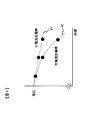
- FIG. 4 shows a graph for explaining a change in internal resistance during charging and discharging.
- a graph denoted by reference numeral 41 represents an example of the relationship between the discharge time and the battery voltage when the battery is discharged with a relatively small constant discharge current.
- the discharge current is small, if the SOC decreases at a constant rate as the discharge time elapses, the battery voltage decreases accordingly at a constant rate. This represents that the internal resistance during discharge is constant. Therefore, in this case, similarly to the case of FIG. 3A described above, the allowable charge / discharge current and the allowable charge / discharge power are obtained by obtaining the magnitude of the current corresponding to the predetermined usable voltage range from the OCV and the internal resistance. Can be determined.
- a graph denoted by reference numeral 42 represents an example of a relationship between a discharge time and a battery voltage when the battery is discharged with a relatively large constant discharge current.
- this graph 42 when the discharge current is large, if the SOC decreases at a constant rate as the discharge time elapses, the battery voltage decreases at an accelerated rate accordingly. This indicates that the internal resistance during discharge is not constant and the internal resistance gradually increases as the discharge proceeds. Therefore, in this case, if the allowable charge / discharge current and the allowable charge / discharge power are determined with the internal resistance set to a constant value, a value larger than the actual value is obtained as in the case of FIG.
- the battery may be in an overcharged state or an overdischarged state, which may cause a reduction in safety or deterioration of the battery.
- the example at the time of discharge is shown in FIG. 4, it is the same also at the time of charge.
- the battery pack controller 150 takes into account the temperature, charge / discharge time, charge / discharge current, etc. of the battery pack 110 during charge / discharge.
- the calculated internal resistance and no-load voltage of the assembled battery 110 are corrected according to the charge / discharge status. Thereby, the allowable charge / discharge current and the allowable charge / discharge power can be accurately obtained.
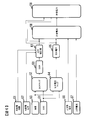
- FIG. 5 is a control block diagram showing an allowable value calculation process by the conventional charge / discharge control as described above.
- the control block 50, 51 obtains the battery temperature and SOC from the battery measurement information, respectively, and based on these values, the map information (internal resistance) stored in advance ( The DCR map) is referred to in the control block 52.
- the DCR map the relationship between the SOC and the internal resistance (DCR) for each temperature of the battery to be controlled is recorded, and the internal resistance of the battery can be obtained by referring to this.
- the control block 53 the internal resistance of the battery is calculated based on the reference result of the DCR map performed in the control block 52.
- control block 54 refers to the OCV map information (OCV map) stored in advance based on the SOC acquired in the control block 51.
- OCV map the relationship between the SOC and the OCV is recorded for the battery to be controlled, and the OCV of the battery can be obtained by referring to this.
- control block 55 the OCV of the battery is calculated based on the reference result of the OCV map performed in the control block 52.
- the upper and lower limit voltages and the upper limit current set in advance are respectively acquired.
- the allowable current of the battery at the time of charging / discharging that is, the allowable charging / discharging current is calculated.
- the control block 59 based on the calculation result of the allowable charging / discharging current performed in the control block 58 and the internal resistance and OCV calculated in the control blocks 53, 55, the allowable power of the battery at the time of charging / discharging, that is, the allowable charging / discharging. Discharge power is calculated.
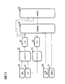
- FIG. 6 is a control block diagram showing an allowable value calculation process by charge / discharge control of the present invention. This control block diagram is different from the control block diagram of the allowable value calculation processing by the conventional charge / discharge control shown in FIG. , 65 are different from each other.
- the control blocks 61 and 62 obtain the charge / discharge time and charge / discharge current of the battery, respectively, and the internal resistance calculated by the control block 53 is calculated based on these values. Correction is performed by the control block 63. Further, the control block 64 refers to the pre-stored map information of the intercept voltage (intercept voltage map) based on the temperature and the SOC acquired by the control blocks 50 and 51, respectively. In the intercept voltage map, the relationship between the charge / discharge time and charge / discharge current and the intercept voltage described in FIG. 3 is recorded for the battery to be controlled, and the intercept voltage as described above is obtained by referring to this. Can do. In the control block 65, the intercept voltage of the battery is calculated based on the reference result of the intercept voltage map performed in the control block 64. By using this intercept voltage instead of the OCV, the no-load voltage of the battery is corrected from the OCV to the intercept voltage.
- control blocks 58 and 59 based on the upper and lower limit voltages and the upper limit current acquired in the control blocks 56 and 57, the internal resistance corrected in the control block 63, and the intercept voltage calculated in place of the OCV in the control block 65, respectively.
- the allowable current and allowable power of the battery at the time of charging / discharging are calculated. Thereby, the allowable charge / discharge current and the allowable charge / discharge power according to the charge / discharge status of the battery are calculated.
- FIG. 7 is a flowchart showing a procedure of an allowable value calculation process by charge / discharge control of the present invention as described above.
- the assembled battery control unit 150 executes an allowable value calculation process according to this flowchart.
- the assembled battery control unit 150 acquires battery measurement information from the single cell management unit 120, the current detection unit 130, and the voltage detection unit 140 by the acquisition unit 150 a. That is, the battery voltage and temperature information is acquired from the single cell management unit 120, the charge / discharge current information is acquired from the current detection unit 130, and the total voltage information from the voltage detection unit 140 is acquired as battery measurement information.
- the assembled battery control unit 150 measures the charge / discharge time by the time measurement unit 150b.
- the charging duration is measured as charging / discharging time when charging, and the discharging duration is measured when discharging, respectively.
- the assembled battery control unit 150 calculates the SOC by the SOC calculation unit 150c.
- the amount of change in the electric energy stored in the assembled battery 110 is obtained by integrating the charge / discharge current included in the battery measurement information acquired in step 1101.
- the SOC can be calculated by estimating the current stored power amount in the assembled battery 110 based on the change amount of the power amount thus obtained. Note that the SOC may be calculated by other methods.
- step 1104 the assembled battery control unit 150 calculates the internal resistance (DCR) by the internal resistance calculation unit 150d.
- DCR internal resistance
- the DCR map stored in the storage unit 180 is referred to, and the internal resistance value corresponding to the temperature acquired as the battery measurement information in step 1101 and the SOC calculated in step 1103 is searched from the DCR map.
- the internal resistance according to the characteristics of the assembled battery 110 can be accurately calculated from the temperature and the SOC.
- the assembled battery control unit 150 corrects the internal resistance (DCR) calculated in step 1104 by the correction unit 150e.
- a correction coefficient for the internal resistance is determined based on the charge / discharge time measured in step 1102 and the charge / discharge current acquired as battery measurement information in step 1101.
- a correction coefficient map reflecting changes in battery voltage during charging / discharging as described in FIG. 4 is stored in advance in the storage unit 180, and is referred to according to the charging / discharging time and charging / discharging current. Determine the correction factor.
- multiplying the internal resistance calculated in step 1104 by this correction coefficient it is possible to obtain a correction value of the internal resistance according to the charge / discharge time and the charge / discharge current.
- a function of a correction coefficient having charging / discharging time and charging / discharging current as variables is defined, and the correction coefficient is determined by using this function.
- the internal resistance may be corrected by determining.
- the change in the battery voltage as shown in the graph 42 in FIG. 4 is noticeable when the battery temperature is equal to or higher than a predetermined value.
- the processing in step 1105 may be omitted so that the internal resistance is not corrected.
- the assembled battery control unit 150 calculates the intercept voltage as described with reference to FIG.
- the intercept voltage map stored in the storage unit 180 is referenced, and the intercept voltage value corresponding to the temperature acquired as the battery measurement information in step 1101 and the SOC calculated in step 1103 is searched from the intercept voltage map. To do.
- the intercept voltage according to the characteristic of the assembled battery 110 can be accurately calculated from the temperature and the SOC.
- the intercept voltage may be calculated by defining a function of the intercept voltage using the temperature and SOC as variables and using this function.
- the assembled battery control unit 150 calculates the allowable charge / discharge current candidate value I by the allowable value calculation unit 150g.
- an allowable charge is obtained by the following equation (1).
- a discharge current candidate value I is calculated. For example, in the case of a lithium ion battery that can be used in the range of 2.0 to 4.2 V, 2.0 V is stored in the storage unit 180 as the lower limit voltage.
- I (intercept voltage ⁇ lower limit voltage) / corrected internal resistance (1)
- step 1108 the assembled battery control unit 150 determines whether the allowable charge / discharge current candidate value I calculated in step 1107 is larger than a predetermined upper limit current by the allowable value calculation unit 150g.
- the upper limit current is stored in advance in the storage unit 180 in consideration of safety during charging and discharging.
- step 1108 When it is determined in step 1108 that the allowable charge / discharge current candidate value I is larger than the upper limit current, the assembled battery control unit 150 sets the allowable charge / discharge current to the upper limit current in step 1109. On the other hand, when it determines with the candidate value I of allowable charging / discharging current being below an upper limit electric current, the assembled battery control part 150 makes the candidate value I the allowable charging / discharging current in step 1110. When step 1109 or 1110 is executed, the process proceeds to step 1111.
- step 1111 the assembled battery control unit 150 calculates the allowable charge / discharge power by the allowable value calculation unit 150g.
- step 1111 the assembled battery control part 150 complete
- the confirmer calculates the OCV and internal resistance of the assembled battery 110 based on the calculation result of the SOC acquired from the assembled battery control unit 150 and the contents of the known OCV map and DCR map, and the allowable charge / discharge current. Alternatively, the allowable charge / discharge power is calculated. Then, these calculated values are compared with the value of the allowable charge / discharge current or the allowable charge / discharge power acquired from the assembled battery control unit 150. As a result, if the two values do not match, it is determined that the allowable value calculation processing according to the present invention is executed in the assembled battery control unit 150, and there is a possibility that the intercept voltage may be used instead of the OCV. Can do. In addition, since the difference of said value becomes remarkable especially at low temperature, it is preferable to confirm below below predetermined temperature.
- the confirmer observes the state of change in the value of the internal resistance calculated based on the calculation result of the SOC acquired from the assembled battery control unit 150 when the assembled battery 110 is continuously charged and discharged.
- the allowable value calculation processing according to the present invention is executed in the assembled battery control unit 150, and is based on the charge / discharge time and the charge / discharge current. Therefore, it can be determined that the internal resistance may be corrected.
- the change of said internal resistance becomes remarkable especially when charging / discharging electric current is large, it is preferable to confirm with more than fixed charging / discharging electric current.
- the assembled battery control unit 150 calculates the allowable current and allowable power during charging / discharging of the assembled battery 110 from the no-load voltage and the internal resistance of the assembled battery 110. At this time, the no-load voltage and the internal resistance are corrected according to the charge / discharge status of the assembled battery 110. Since it did in this way, the electric current and electric power which are accept
- the assembled battery control unit 150 acquires the temperature of the assembled battery 110 by the acquisition unit 150a (step 1101), and calculates the SOC of the assembled battery 110 by the SOC calculation unit 150c (step 1103). Based on these temperatures and SOC, the intercept voltage calculation unit 150f calculates the intercept voltage when the charge / discharge current is 0 in the graph representing the relationship between the charge / discharge current of the assembled battery 110 and the voltage of the assembled battery 110. (Step 1106). The intercept voltage calculated in this way is changed to the no-load voltage used for calculating the allowable current and the allowable power during charging / discharging of the assembled battery 110 instead of the OCV, thereby correcting the no-load voltage. As a result, the no-load voltage can be corrected correctly reflecting the change in the intercept voltage during charging and discharging.
- the intercept voltage calculation unit 150f refers to the intercept voltage map stored in advance in the storage unit 180, and calculates the intercept voltage corresponding to the temperature acquired by the acquisition unit 150a and the SOC calculated by the SOC calculation unit 150c. . Since it did in this way, the intercept voltage according to the characteristic of the assembled battery 110 can be calculated correctly.
- the assembled battery control unit 150 acquires the charging / discharging current of the assembled battery 110 by the acquiring unit 150a (step 1101), measures the charging / discharging time of the assembled battery 110 by the time measuring unit 150b (step 1102), and The internal resistance of the assembled battery 110 is calculated by the resistance calculation unit 150d (step 1104).
- the correction unit 150e corrects the internal resistance based on the charge / discharge time and the charge / discharge current (step 1105). Since it did in this way, internal resistance can be correct
- the correction unit 150e may not correct the internal resistance when the temperature acquired by the acquisition unit 150a is lower than a predetermined value. In this way, unnecessary processing can be omitted in a temperature range in which a change in internal resistance does not appear during charging and discharging.
- the correction unit 150e can obtain the correction value of the internal resistance corresponding to the charge / discharge time and the charge / discharge current with reference to the correction coefficient map stored in the storage unit 180 in advance. In this way, the internal resistance can be accurately corrected according to the characteristics of the assembled battery 110.
- the present invention is not limited to the above-described embodiment, and various design changes can be made without departing from the spirit of the present invention.
- an example in which the internal resistance and intercept voltage of the assembled battery 110 are calculated or the correction coefficient of the internal resistance is calculated by referring to various types of map information has been described. Is not necessarily performed with reference to the map information.
- calculation of either the allowable charge / discharge current or the allowable charge / discharge power may be omitted.
- either the processing of the intercept voltage calculation by the intercept voltage calculation unit 150f or the correction of the internal resistance by the correction unit 150e may be omitted.
- the OCV may be calculated instead of the intercept voltage, and the allowable charge / discharge current and the allowable charge / discharge power may be calculated using this. That is, the present invention can be applied to a battery control device that calculates at least one of allowable current and allowable power during charging / discharging of a battery from no-load voltage and internal resistance. It corrects at least one of voltage and internal resistance.
Abstract
Priority Applications (5)
| Application Number | Priority Date | Filing Date | Title |
|---|---|---|---|
| JP2014516584A JP5868499B2 (ja) | 2012-05-24 | 2012-05-24 | 電池制御装置 |
| EP12877273.8A EP2857854B1 (fr) | 2012-05-24 | 2012-05-24 | Dispositif de commande de batterie |
| PCT/JP2012/063307 WO2013175606A1 (fr) | 2012-05-24 | 2012-05-24 | Dispositif de commande de batterie |
| US14/403,330 US9557388B2 (en) | 2012-05-24 | 2012-05-24 | Battery control device |
| CN201280073358.6A CN104471414B (zh) | 2012-05-24 | 2012-05-24 | 电池控制装置 |
Applications Claiming Priority (1)
| Application Number | Priority Date | Filing Date | Title |
|---|---|---|---|
| PCT/JP2012/063307 WO2013175606A1 (fr) | 2012-05-24 | 2012-05-24 | Dispositif de commande de batterie |
Publications (1)
| Publication Number | Publication Date |
|---|---|
| WO2013175606A1 true WO2013175606A1 (fr) | 2013-11-28 |
Family
ID=49623337
Family Applications (1)
| Application Number | Title | Priority Date | Filing Date |
|---|---|---|---|
| PCT/JP2012/063307 WO2013175606A1 (fr) | 2012-05-24 | 2012-05-24 | Dispositif de commande de batterie |
Country Status (5)
| Country | Link |
|---|---|
| US (1) | US9557388B2 (fr) |
| EP (1) | EP2857854B1 (fr) |
| JP (1) | JP5868499B2 (fr) |
| CN (1) | CN104471414B (fr) |
| WO (1) | WO2013175606A1 (fr) |
Cited By (7)
| Publication number | Priority date | Publication date | Assignee | Title |
|---|---|---|---|---|
| JP2014232649A (ja) * | 2013-05-29 | 2014-12-11 | 日産自動車株式会社 | 電池温度推定装置及び電池温度推定方法 |
| JP2016082728A (ja) * | 2014-10-17 | 2016-05-16 | 株式会社日立製作所 | 二次電池の制御方法 |
| WO2017130614A1 (fr) * | 2016-01-27 | 2017-08-03 | 日立オートモティブシステムズ株式会社 | Dispositif de commande de batterie |
| EP3171187A4 (fr) * | 2014-07-17 | 2018-04-04 | Hitachi Automotive Systems, Ltd. | Dispositif de détection d'état de batterie, système de batterie rechargeable, produit programme, et procédé de détection d'état de batterie |
| EP3171186A4 (fr) * | 2014-07-17 | 2018-04-04 | Hitachi Automotive Systems, Ltd. | Dispositif de détection d'état de batterie, système de batterie rechargeable, produit-programme, et procédé de détection d'état de batterie |
| KR20180087039A (ko) * | 2017-01-24 | 2018-08-01 | 주식회사 엘지화학 | 배터리 관리 장치 및 방법 |
| CN113884883A (zh) * | 2021-10-19 | 2022-01-04 | 合肥国轩高科动力能源有限公司 | 锂离子电池循环中直流内阻的校正方法及装置 |
Families Citing this family (11)
| Publication number | Priority date | Publication date | Assignee | Title |
|---|---|---|---|---|
| WO2014129025A1 (fr) * | 2013-02-19 | 2014-08-28 | 古河電気工業株式会社 | Procédé de détermination de détérioration de batterie secondaire et dispositif de détermination de détérioration de batterie secondaire |
| KR102165937B1 (ko) * | 2014-05-30 | 2020-10-14 | 삼성전자주식회사 | 배터리 관리 방법 및 장치 |
| JP6787660B2 (ja) * | 2015-12-10 | 2020-11-18 | ビークルエナジージャパン株式会社 | 電池制御装置、動力システム |
| CN109661585B (zh) * | 2016-10-26 | 2021-06-29 | 日本汽车能源株式会社 | 电池控制装置 |
| DE102018200976A1 (de) * | 2018-01-23 | 2019-07-25 | Volkswagen Aktiengesellschaft | Verfahren zum Steuern des Ladens einer Batterieeinheit, Verfahren zum Laden einer Batterieeinheit, Steuereinheit, Ladesystem, Batteriesystem und Arbeitsvorrichtung |
| CN109031141B (zh) * | 2018-07-13 | 2021-06-04 | 江苏塔菲尔新能源科技股份有限公司 | 一种锂离子电池析锂的预测方法 |
| TWI670506B (zh) * | 2018-07-27 | 2019-09-01 | 連恩微電子有限公司 | 電池管理系統 |
| CN112557919A (zh) * | 2019-09-25 | 2021-03-26 | 郑州深澜动力科技有限公司 | 一种电池开路电压的测试方法 |
| DE102020126729A1 (de) * | 2020-10-12 | 2022-04-14 | TWAICE Technologies GmbH | Korrigierte Klemmenspannung für Batterien |
| US11789087B2 (en) * | 2021-03-03 | 2023-10-17 | Semiconductor Components Industries, Llc | Battery charge support system for reducing energy loss |
| CN113879174B (zh) * | 2021-10-29 | 2024-01-12 | 重庆长安汽车股份有限公司 | 一种动力电池放电电流限制方法、系统及纯电动汽车 |
Citations (7)
| Publication number | Priority date | Publication date | Assignee | Title |
|---|---|---|---|---|
| WO2004008166A1 (fr) * | 2002-07-12 | 2004-01-22 | Toyota Jidosha Kabushiki Kaisha | Estimateur d'etat de charge d'une batterie |
| JP2006345634A (ja) | 2005-06-08 | 2006-12-21 | Fuji Heavy Ind Ltd | 蓄電デバイスの制御装置 |
| US20070200567A1 (en) * | 2006-02-24 | 2007-08-30 | Denso Corporation | Apparatus for calculating quantity indicating charged state of on-vehicle battery |
| US20100185405A1 (en) * | 2009-01-13 | 2010-07-22 | Hitachi Vehicle Energy, Ltd. | Battery Control Device |
| JP2010221828A (ja) * | 2009-03-23 | 2010-10-07 | Fujitsu Ten Ltd | エコラン制御装置 |
| US20110234166A1 (en) * | 2010-02-10 | 2011-09-29 | Chin-Chuan Liu | Battery module state detection method |
| WO2011155184A1 (fr) * | 2010-06-08 | 2011-12-15 | Nissan Motor Co., Ltd. | Appareil de traitement arithmétique servant à calculer une résistance interne/tension en circuit ouvert d'une batterie secondaire |
Family Cites Families (12)
| Publication number | Priority date | Publication date | Assignee | Title |
|---|---|---|---|---|
| JPH11346444A (ja) | 1998-06-02 | 1999-12-14 | Toyota Motor Corp | 電池充電状態の推定方法 |
| JP2002189066A (ja) | 2000-12-22 | 2002-07-05 | Hitachi Ltd | 二次電池残量推定法 |
| DE10207659B4 (de) * | 2001-02-23 | 2006-09-28 | Yazaki Corp. | Verfahren und Vorrichtung zum Schätzen einer Klemmenspannung einer Batterie, Verfahren und Vorrichtung zum Berechnen einer Leerlaufspannung einer Batterie sowie Verfahren und Vorrichtung zum Berechnen der Batteriekapazität |
| JP4130425B2 (ja) * | 2003-07-29 | 2008-08-06 | パナソニックEvエナジー株式会社 | 二次電池の充放電電気量推定方法および装置、二次電池の分極電圧推定方法および装置、並びに二次電池の残存容量推定方法および装置 |
| JP2005227164A (ja) * | 2004-02-13 | 2005-08-25 | Toyota Motor Corp | 二次電池の残存容量算出装置 |
| JP4560540B2 (ja) * | 2005-01-27 | 2010-10-13 | プライムアースEvエナジー株式会社 | 二次電池の充放電電気量推定方法および装置、二次電池の分極電圧推定方法および装置、並びに二次電池の残存容量推定方法および装置 |
| JP5130608B2 (ja) * | 2005-05-31 | 2013-01-30 | 日産自動車株式会社 | 電池制御装置 |
| WO2010005079A1 (fr) * | 2008-07-11 | 2010-01-14 | トヨタ自動車株式会社 | Dispositif de commande de charge/décharge de batterie et véhicule hybride utilisant celui-ci |
| JP4930482B2 (ja) * | 2008-09-30 | 2012-05-16 | 株式会社デンソー | バッテリの充放電制御装置 |
| JP5656415B2 (ja) * | 2009-03-26 | 2015-01-21 | プライムアースEvエナジー株式会社 | 二次電池の状態判定装置及び制御装置 |
| JP5496612B2 (ja) * | 2009-11-11 | 2014-05-21 | 三洋電機株式会社 | 電池の充放電可能電流演算方法及び電源装置並びにこれを備える車両 |
| US8872481B2 (en) * | 2011-04-27 | 2014-10-28 | General Electric Company | Systems and methods for predicting battery power-delivery performance |
-
2012
- 2012-05-24 JP JP2014516584A patent/JP5868499B2/ja active Active
- 2012-05-24 WO PCT/JP2012/063307 patent/WO2013175606A1/fr active Application Filing
- 2012-05-24 EP EP12877273.8A patent/EP2857854B1/fr active Active
- 2012-05-24 CN CN201280073358.6A patent/CN104471414B/zh active Active
- 2012-05-24 US US14/403,330 patent/US9557388B2/en active Active
Patent Citations (7)
| Publication number | Priority date | Publication date | Assignee | Title |
|---|---|---|---|---|
| WO2004008166A1 (fr) * | 2002-07-12 | 2004-01-22 | Toyota Jidosha Kabushiki Kaisha | Estimateur d'etat de charge d'une batterie |
| JP2006345634A (ja) | 2005-06-08 | 2006-12-21 | Fuji Heavy Ind Ltd | 蓄電デバイスの制御装置 |
| US20070200567A1 (en) * | 2006-02-24 | 2007-08-30 | Denso Corporation | Apparatus for calculating quantity indicating charged state of on-vehicle battery |
| US20100185405A1 (en) * | 2009-01-13 | 2010-07-22 | Hitachi Vehicle Energy, Ltd. | Battery Control Device |
| JP2010221828A (ja) * | 2009-03-23 | 2010-10-07 | Fujitsu Ten Ltd | エコラン制御装置 |
| US20110234166A1 (en) * | 2010-02-10 | 2011-09-29 | Chin-Chuan Liu | Battery module state detection method |
| WO2011155184A1 (fr) * | 2010-06-08 | 2011-12-15 | Nissan Motor Co., Ltd. | Appareil de traitement arithmétique servant à calculer une résistance interne/tension en circuit ouvert d'une batterie secondaire |
Non-Patent Citations (1)
| Title |
|---|
| See also references of EP2857854A4 * |
Cited By (15)
| Publication number | Priority date | Publication date | Assignee | Title |
|---|---|---|---|---|
| JP2014232649A (ja) * | 2013-05-29 | 2014-12-11 | 日産自動車株式会社 | 電池温度推定装置及び電池温度推定方法 |
| US10686229B2 (en) | 2014-07-17 | 2020-06-16 | Vehicle Energy Japan Inc. | Battery state detection device, secondary battery system, program product, and battery state detection method |
| EP3171187A4 (fr) * | 2014-07-17 | 2018-04-04 | Hitachi Automotive Systems, Ltd. | Dispositif de détection d'état de batterie, système de batterie rechargeable, produit programme, et procédé de détection d'état de batterie |
| EP3171186A4 (fr) * | 2014-07-17 | 2018-04-04 | Hitachi Automotive Systems, Ltd. | Dispositif de détection d'état de batterie, système de batterie rechargeable, produit-programme, et procédé de détection d'état de batterie |
| US10725111B2 (en) | 2014-07-17 | 2020-07-28 | Vehicle Energy Japan Inc. | Battery state detection device, secondary battery system, program product, and battery state detection method |
| JP2016082728A (ja) * | 2014-10-17 | 2016-05-16 | 株式会社日立製作所 | 二次電池の制御方法 |
| US10840722B2 (en) | 2016-01-27 | 2020-11-17 | Vehicle Energy Japan, Inc. | Battery control device |
| JPWO2017130614A1 (ja) * | 2016-01-27 | 2018-07-19 | 日立オートモティブシステムズ株式会社 | 電池制御装置 |
| WO2017130614A1 (fr) * | 2016-01-27 | 2017-08-03 | 日立オートモティブシステムズ株式会社 | Dispositif de commande de batterie |
| JP2019515621A (ja) * | 2017-01-24 | 2019-06-06 | エルジー・ケム・リミテッド | バッテリー管理装置及び方法 |
| KR102066703B1 (ko) | 2017-01-24 | 2020-01-15 | 주식회사 엘지화학 | 배터리 관리 장치 및 방법 |
| KR20180087039A (ko) * | 2017-01-24 | 2018-08-01 | 주식회사 엘지화학 | 배터리 관리 장치 및 방법 |
| US11125825B2 (en) | 2017-01-24 | 2021-09-21 | Lg Chem, Ltd. | Apparatus and method for managing battery |
| CN113884883A (zh) * | 2021-10-19 | 2022-01-04 | 合肥国轩高科动力能源有限公司 | 锂离子电池循环中直流内阻的校正方法及装置 |
| CN113884883B (zh) * | 2021-10-19 | 2024-02-06 | 合肥国轩高科动力能源有限公司 | 锂离子电池循环中直流内阻的校正方法及装置 |
Also Published As
| Publication number | Publication date |
|---|---|
| EP2857854A1 (fr) | 2015-04-08 |
| EP2857854A4 (fr) | 2016-03-09 |
| JP5868499B2 (ja) | 2016-02-24 |
| US20150108991A1 (en) | 2015-04-23 |
| CN104471414A (zh) | 2015-03-25 |
| EP2857854B1 (fr) | 2019-05-08 |
| US9557388B2 (en) | 2017-01-31 |
| JPWO2013175606A1 (ja) | 2016-01-12 |
| CN104471414B (zh) | 2017-04-05 |
Similar Documents
| Publication | Publication Date | Title |
|---|---|---|
| JP5868499B2 (ja) | 電池制御装置 | |
| US11124072B2 (en) | Battery control device and electric motor vehicle system | |
| US10209317B2 (en) | Battery control device for calculating battery deterioration based on internal resistance increase rate | |
| US10840722B2 (en) | Battery control device | |
| US9685807B2 (en) | Battery control device | |
| KR101589155B1 (ko) | 전기 저장 시스템 | |
| JP6111275B2 (ja) | 電池制御装置 | |
| JP5621818B2 (ja) | 蓄電システムおよび均等化方法 | |
| EP3115800A1 (fr) | Procédé de mesure de courant de bloc batterie | |
| JP5784108B2 (ja) | 充電制御装置 | |
| US20140239914A1 (en) | Battery controller | |
| US20170274794A1 (en) | Cell status estimation device and power supply device | |
| CN106662620B (zh) | 电池状态探测装置、二次电池系统、存储介质、电池状态探测方法 | |
| JP2016091613A (ja) | 電池システム及び容量回復方法 | |
| US20140184236A1 (en) | Battery control apparatus and battery system | |
| US10393823B2 (en) | Battery system monitoring apparatus | |
| JP5838224B2 (ja) | 電池制御装置 | |
| US20200126516A1 (en) | Display device and vehicle including the same | |
| WO2019142550A1 (fr) | Système de batterie rechargeable | |
| JP5929711B2 (ja) | 充電システムおよび、電圧降下量の算出方法 | |
| JP2013127440A (ja) | 蓄電システム |
Legal Events
| Date | Code | Title | Description |
|---|---|---|---|
| 121 | Ep: the epo has been informed by wipo that ep was designated in this application |
Ref document number: 12877273 Country of ref document: EP Kind code of ref document: A1 |
|
| ENP | Entry into the national phase |
Ref document number: 2014516584 Country of ref document: JP Kind code of ref document: A |
|
| NENP | Non-entry into the national phase |
Ref country code: DE |
|
| WWE | Wipo information: entry into national phase |
Ref document number: 14403330 Country of ref document: US Ref document number: 2012877273 Country of ref document: EP |