以下、本発明の実施形態を図面に基づいて説明する。以下に説明する実施形態は、たとえば電気自動車(EV)、ハイブリッド自動車(HEV)、プラグインハイブリッド自動車(PHEV)等の電源を構成する電池システムに対して適用することができる。
Hereinafter, embodiments of the present invention will be described with reference to the drawings. The embodiment described below can be applied to a battery system that constitutes a power source of an electric vehicle (EV), a hybrid vehicle (HEV), a plug-in hybrid vehicle (PHEV), and the like.
以下の実施形態により説明する電池システムでは、たとえばリチウムイオン電池を採用することができる。なお、以下の実施形態では単電池を直列に接続して組電池を構成しているが、単電池を並列接続したものを直列接続して組電池を構成してもよいし、直列接続した単電池を並列接続して組電池を構成してもよい。
In the battery system described by the following embodiments, for example, a lithium ion battery can be adopted. In the following embodiments, the assembled batteries are configured by connecting the cells in series. However, the assembled batteries may be configured by connecting the cells connected in parallel, or by connecting the cells connected in series. A battery pack may be configured by connecting batteries in parallel.
図1は、本発明の一実施形態に係る電池制御装置を搭載した電池システム100とその周辺の構成を示すブロック図である。電池システム100は、リレー300と310を介してインバータ400に接続され、リレー320と330を介して充電器420に接続される。電池システム100は、組電池110、単電池管理部120、電流検知部130、電圧検知部140、組電池制御部150、および記憶部180を備える。
FIG. 1 is a block diagram showing a configuration of a battery system 100 equipped with a battery control device according to an embodiment of the present invention and its periphery. Battery system 100 is connected to inverter 400 via relays 300 and 310, and connected to charger 420 via relays 320 and 330. The battery system 100 includes an assembled battery 110, a single battery management unit 120, a current detection unit 130, a voltage detection unit 140, an assembled battery control unit 150, and a storage unit 180.
組電池110は、複数の単電池111から構成される。単電池管理部120は、各単電池111の電池電圧や温度を検知することにより、各単電池111の状態を監視し、その結果を組電池制御部150へ出力する。電流検知部130は、電池システム100に流れる充放電電流を検知し、検知した電流値を組電池制御部150へ出力する。電圧検知部140は、組電池110の総電圧を検知し、検知した電圧値を組電池制御部150へ出力する。電池制御装置としての組電池制御部150は、これらを基に組電池110を制御する。
The assembled battery 110 is composed of a plurality of unit cells 111. The unit cell management unit 120 monitors the state of each unit cell 111 by detecting the battery voltage and temperature of each unit cell 111, and outputs the result to the assembled battery control unit 150. The current detection unit 130 detects the charge / discharge current flowing through the battery system 100 and outputs the detected current value to the assembled battery control unit 150. The voltage detection unit 140 detects the total voltage of the assembled battery 110 and outputs the detected voltage value to the assembled battery control unit 150. The assembled battery control unit 150 as a battery control device controls the assembled battery 110 based on these.
組電池制御部150は、たとえばマイコンやメモリによって実現されるものであり、取得部150a、時間計測部150b、SOC算出部150c、内部抵抗算出部150d、補正部150e、切片電圧算出部150f、および許容値算出部150gを機能的に有している。
The assembled battery control unit 150 is realized by, for example, a microcomputer or a memory, and includes an acquisition unit 150a, a time measurement unit 150b, an SOC calculation unit 150c, an internal resistance calculation unit 150d, a correction unit 150e, an intercept voltage calculation unit 150f, The allowable value calculation unit 150g is functionally provided.
取得部150aは、単電池管理部120、電流検知部130および電圧検知部140から、前述のような組電池110の状態に関する測定結果の情報をそれぞれ取得する。すなわち、単電池管理部120が送信する各単電池111の電池電圧や温度の情報と、電流検知部130が送信する充放電電流の情報と、電圧検知部140が送信する組電池110の総電圧の情報とを受け取る。なお、以下の説明では、組電池制御部150が取得するこれらの組電池110の状態に関する測定結果の情報のことを電池測定情報と総称する。
The acquisition unit 150a acquires information on measurement results regarding the state of the assembled battery 110 as described above from the single cell management unit 120, the current detection unit 130, and the voltage detection unit 140, respectively. That is, information on the battery voltage and temperature of each unit cell 111 transmitted by the unit cell management unit 120, information on the charge / discharge current transmitted by the current detection unit 130, and the total voltage of the assembled battery 110 transmitted by the voltage detection unit 140 And receive information. In the following description, the measurement result information regarding the state of the assembled battery 110 acquired by the assembled battery control unit 150 is collectively referred to as battery measurement information.
時間計測部150bは、組電池制御部150に内蔵されているタイマを用いて、組電池110の充放電時間を計測する。すなわち、充電開始から充電終了までの時間や、放電開始から放電終了までの時間を充放電時間として計測する。
The time measuring unit 150 b measures the charge / discharge time of the assembled battery 110 using a timer built in the assembled battery control unit 150. That is, the time from the start of charge to the end of charge and the time from the start of discharge to the end of discharge are measured as the charge / discharge time.
SOC算出部150cは、取得部150aが取得した上記の電池測定情報に基づいて、組電池110の充電状態、すなわちSOCを算出する。たとえば、組電池110の充放電電流を積算することで、組電池110に蓄積されている電力量の変化量を求め、これに基づいてSOCを算出することができる。
The SOC calculation unit 150c calculates the state of charge of the assembled battery 110, that is, the SOC, based on the battery measurement information acquired by the acquisition unit 150a. For example, by integrating the charging / discharging current of the assembled battery 110, the amount of change in the amount of power stored in the assembled battery 110 can be obtained, and the SOC can be calculated based on this.
内部抵抗算出部150dは、取得部150aにより取得された電池測定情報のうち温度の情報と、SOC算出部150cにより算出されたSOCとに基づいて、組電池110の内部抵抗を算出する。この内部抵抗の算出は、記憶部180に記憶されている内部抵抗のマップ情報を用いて、後で詳細に説明するような方法により行われる。
The internal resistance calculation unit 150d calculates the internal resistance of the assembled battery 110 based on the temperature information in the battery measurement information acquired by the acquisition unit 150a and the SOC calculated by the SOC calculation unit 150c. The calculation of the internal resistance is performed by a method described in detail later using map information of the internal resistance stored in the storage unit 180.
補正部150eは、内部抵抗算出部150dにより算出された組電池110の内部抵抗を補正する。この内部抵抗の補正は、時間計測部150bにより計測された充放電時間に基づいて、後で説明するような方法により行われる。
The correction unit 150e corrects the internal resistance of the assembled battery 110 calculated by the internal resistance calculation unit 150d. The correction of the internal resistance is performed by a method described later based on the charge / discharge time measured by the time measuring unit 150b.
切片電圧算出部150fは、取得部150aにより取得された電池測定情報のうち温度の情報と、SOC算出部150cにより算出されたSOCとに基づいて、組電池110に対する切片電圧を算出する。切片電圧とは、組電池110の充放電電流と電圧の関係をグラフで表したときに、そのグラフにおいて充放電電流が0であるときに相当する電圧のことである。この切片電圧の算出は、記憶部180に記憶されている切片電圧のマップ情報を用いて、後で説明するような方法により行われる。
The intercept voltage calculation unit 150f calculates the intercept voltage for the assembled battery 110 based on the temperature information in the battery measurement information acquired by the acquisition unit 150a and the SOC calculated by the SOC calculation unit 150c. The intercept voltage is a voltage corresponding to a charge / discharge current of 0 when the charge / discharge current and voltage of the battery pack 110 are represented in a graph. The calculation of the intercept voltage is performed by a method described later using map information of the intercept voltage stored in the storage unit 180.
許容値算出部150gは、補正部150eにより補正された内部抵抗と、切片電圧算出部150fにより算出された切片電圧とに基づいて、組電池110において許容される充放電電流の許容値(許容充放電電流)を算出する。さらに、この許容充放電電流を基に、組電池110において許容される充放電電力の許容値(許容充放電電力)を算出する。算出されたこれらの値は、組電池制御部150から単電池管理部120や車両制御部200に送信され、充放電時の制御に利用される。
The allowable value calculation unit 150g is based on the internal resistance corrected by the correction unit 150e and the intercept voltage calculated by the intercept voltage calculation unit 150f. Discharge current) is calculated. Furthermore, based on this allowable charge / discharge current, an allowable value of charge / discharge power allowed in the assembled battery 110 (allowable charge / discharge power) is calculated. These calculated values are transmitted from the assembled battery control unit 150 to the single cell management unit 120 and the vehicle control unit 200, and are used for control during charging and discharging.
記憶部180は、組電池制御部150が有する上記の各機能において用いられる様々な情報を記憶するものであり、フラッシュメモリ等を用いて実現される。たとえば、内部抵抗算出部150dが内部抵抗の算出を行うときに利用するマップ情報や、切片電圧算出部150fが切片電圧を算出するときに利用するマップ情報などが、記憶部180において記憶されている。記憶部180に記憶されている情報は、組電池制御部150の制御により、必要に応じて読み出されたり書き換えられたりする。
The storage unit 180 stores various information used in the above functions of the assembled battery control unit 150, and is realized using a flash memory or the like. For example, the storage unit 180 stores map information used when the internal resistance calculation unit 150d calculates internal resistance, map information used when the intercept voltage calculation unit 150f calculates intercept voltage, and the like. . Information stored in the storage unit 180 is read or rewritten as necessary under the control of the assembled battery control unit 150.
組電池110は、電気エネルギーの蓄積および放出(直流電力の充放電)が可能な複数の単電池111を電気的に直列に接続して構成されている。組電池110を構成する各単電池111は、所定の単位数ごとにグループ分けされており、そのグループ単位で単電池管理部120による状態管理や制御が実施される。グループ分けされた各単電池111は、電気的に直列に接続され、単電池群112a、112bを構成している。単電池群112a、112bをそれぞれ構成する単電池111の個数は同数でもよいし、単電池群112aと単電池群112bとで単電池111の個数が異なっていてもよい。
The assembled battery 110 is configured by electrically connecting a plurality of unit cells 111 capable of storing and releasing electrical energy (charging and discharging DC power) in series. The unit cells 111 constituting the assembled battery 110 are grouped by a predetermined number of units, and state management and control by the unit cell management unit 120 are performed in units of groups. The grouped unit cells 111 are electrically connected in series to form unit cell groups 112a and 112b. The number of the single cells 111 constituting each of the single cell groups 112a and 112b may be the same, or the number of the single cells 111 may be different between the single cell group 112a and the single cell group 112b.
単電池管理部120は、組電池110を構成する単電池111の状態を監視する。単電池管理部120は、単電池群112a、112bに対応してそれぞれ設けられた単電池制御部121a、121bを備える。単電池制御部121a、121bは、単電池群112a、112bをそれぞれ構成する各単電池111の状態を監視および制御する。
The single cell management unit 120 monitors the state of the single cells 111 constituting the assembled battery 110. The unit cell management unit 120 includes unit cell control units 121a and 121b provided corresponding to the unit cell groups 112a and 112b, respectively. The unit cell control units 121a and 121b monitor and control the state of each unit cell 111 constituting each unit cell group 112a and 112b.
なお、本実施形態では、説明を簡略化するために、4個の単電池111を電気的に直列接続して単電池群112aと112bを構成し、単電池群112aと112bをさらに電気的に直列接続して合計8個の単電池111を備える組電池110とした。しかし、組電池110を構成する単電池群や単電池の数は、これに限定されるものではない。
In the present embodiment, in order to simplify the description, four unit cells 111 are electrically connected in series to form unit cell groups 112a and 112b, and the unit cell groups 112a and 112b are further electrically connected. An assembled battery 110 including a total of eight unit cells 111 connected in series was obtained. However, the number of unit cells or the number of unit cells constituting the assembled battery 110 is not limited to this.
組電池制御部150と単電池管理部120は、フォトカプラに代表される絶縁素子170および信号通信手段160を介して、互いに信号を送受信する。
The assembled battery control unit 150 and the single cell management unit 120 transmit and receive signals to and from each other via an insulating element 170 typified by a photocoupler and a signal communication unit 160.
ここで、組電池制御部150と、単電池管理部120を構成する単電池制御部121aおよび121bとの間の通信について説明する。単電池制御部121aおよび121bは、それぞれが監視する単電池群112aおよび112bの電位の高い順にしたがって直列に接続されている。組電池制御部150が単電池管理部120に送信した信号は、信号通信手段160および絶縁素子170を介して単電池制御部121aに入力される。単電池制御部121aの出力は信号通信手段160を介して単電池制御部121bに入力され、最下位の単電池制御部121bの出力は絶縁素子170および信号通信手段160を介して組電池制御部150へと伝送される。本実施形態では、単電池制御部121aと単電池制御部121bの間は絶縁素子170を介していないが、絶縁素子170を介して信号を送受信することもできる。
Here, communication between the assembled battery control unit 150 and the unit cell control units 121a and 121b constituting the unit cell management unit 120 will be described. The cell control units 121a and 121b are connected in series according to the descending order of potentials of the cell groups 112a and 112b monitored by each. A signal transmitted from the assembled battery control unit 150 to the unit cell management unit 120 is input to the unit cell control unit 121a via the signal communication unit 160 and the insulating element 170. The output of the unit cell control unit 121a is input to the unit cell control unit 121b via the signal communication unit 160, and the output of the lowest unit cell control unit 121b is supplied to the assembled battery control unit via the insulating element 170 and the signal communication unit 160. 150. In the present embodiment, the insulating cell 170 is not interposed between the single cell control unit 121a and the single cell control unit 121b, but signals can be transmitted and received via the insulating device 170.
車両制御部200は、組電池制御部150が送信する情報を用いて、リレー300および310を介して電池システム100と接続されるインバータ400を制御する。また、リレー320および330を介して電池システム100に接続される充電器420を制御する。
Vehicle control unit 200 controls inverter 400 connected to battery system 100 via relays 300 and 310 using information transmitted by assembled battery control unit 150. In addition, the charger 420 connected to the battery system 100 via the relays 320 and 330 is controlled.
充電器420は、一般家庭の電源や公共施設等に設置されている充電設備を用いて組電池110を充電する際に用いられる。本実施形態では、充電器420は車両制御部200からの指令に基づき充電電圧や充電電流などを制御する構成としているが、組電池制御部150からの指令に基づきこれらの制御を実施してもよい。また、充電器420は車両の構成、充電器420の性能、使用目的、外部の電源の設置条件などに応じて、車両内部に設置してもよいし、車両の外部に設置することもできる。
The charger 420 is used when charging the assembled battery 110 using a charging facility installed in a general household power source or a public facility. In the present embodiment, the charger 420 is configured to control a charging voltage, a charging current, and the like based on a command from the vehicle control unit 200, but even if these controls are performed based on a command from the assembled battery control unit 150, Good. The charger 420 may be installed inside the vehicle or outside the vehicle depending on the configuration of the vehicle, the performance of the charger 420, the purpose of use, the installation conditions of the external power source, and the like.
電池システム100を搭載した車両が走行する際には、車両制御部200の管理のもと、電池システム100がリレー300、310を介してインバータ400に接続される。このとき、組電池110が蓄えているエネルギーを用いて、インバータ400の制御によりモータジェネレータ410が駆動される。また、回生時にはモータジェネレータ410の発電電力により組電池110が充電される。
When a vehicle equipped with the battery system 100 travels, the battery system 100 is connected to the inverter 400 via the relays 300 and 310 under the control of the vehicle control unit 200. At this time, the motor generator 410 is driven by the control of the inverter 400 using the energy stored in the assembled battery 110. Further, during regeneration, the assembled battery 110 is charged by the power generated by the motor generator 410.
一方、電池システム100を備える車両が一般家庭の電源や公共施設等に設置されている充電設備と接続された際には、車両制御部200が発信する情報に基づき、電池システム100がリレー320、330を介して充電器420と接続される。このとき、組電池110が所定の条件になるまで充電される。充電によって組電池110に蓄えられたエネルギーは、次回の車両走行時に利用されると共に、車両内外の電装品等を動作させるためにも利用される。さらに必要に応じて、家庭用の電源に代表される外部電源へも放出される場合がある。
On the other hand, when a vehicle including the battery system 100 is connected to a charging facility installed in a general household power source or a public facility, the battery system 100 is connected to the relay 320, based on information transmitted by the vehicle control unit 200. The battery charger 420 is connected to the charger 420 via 330. At this time, the battery pack 110 is charged until a predetermined condition is met. The energy stored in the assembled battery 110 by charging is used during the next vehicle travel, and is also used to operate electrical components inside and outside the vehicle. Furthermore, it may be discharged to an external power source represented by a household power source as necessary.
図2は、単電池制御部121aの回路構成を示したブロック図である。なお、単電池制御部121aと単電池制御部121bとは、基本的に同一の回路構成を有している。そのため、以下では単電池制御部121aを代表例として説明する。
FIG. 2 is a block diagram showing a circuit configuration of the unit cell control unit 121a. The unit cell control unit 121a and the unit cell control unit 121b basically have the same circuit configuration. Therefore, hereinafter, the single cell control unit 121a will be described as a representative example.
単電池制御部121aは、電圧検出回路122、制御回路123、信号入出力回路124、および温度検知部125を備える。なお、図2では省略しているが、各単電池111間において発生する電池電圧やSOCのばらつきを均等化するための周知のバランシング回路等を単電池制御部121a内にさらに設けてもよい。
The unit cell control unit 121a includes a voltage detection circuit 122, a control circuit 123, a signal input / output circuit 124, and a temperature detection unit 125. Although omitted in FIG. 2, a well-known balancing circuit or the like for equalizing variations in battery voltage and SOC generated between the single cells 111 may be further provided in the single cell control unit 121a.
電圧検出回路122は、各単電池111の端子間電圧をそれぞれ測定することにより、各単電池111の電池電圧を測定する。温度検知部125は、単電池群112a全体の温度を測定し、その温度を単電池群112aを構成する各単電池111の温度として取り扱うことにより、各単電池111の温度を測定する。制御回路123は、これらの測定結果を電圧検出回路122と温度検知部125からそれぞれ受け取り、信号入出力回路124を介して組電池制御部150に送信する。
The voltage detection circuit 122 measures the battery voltage of each unit cell 111 by measuring the voltage between the terminals of each unit cell 111. The temperature detection unit 125 measures the temperature of each unit cell 111 by measuring the temperature of the entire unit cell group 112a and handling the temperature as the temperature of each unit cell 111 constituting the unit cell group 112a. The control circuit 123 receives these measurement results from the voltage detection circuit 122 and the temperature detection unit 125, and transmits them to the assembled battery control unit 150 via the signal input / output circuit 124.
温度測定対象である単電池群112aには温度センサが設置されている。温度検知部125は、この温度センサから出力される単電池群112aの温度に応じた電圧を検出することで、単電池群112aの温度、すなわち各単電池111の温度を測定する。この測定結果は、温度検知部125から制御回路123を介して信号入出力回路124に送信され、信号入出力回路124により単電池制御部121aの外に出力される。この一連の流れを実現するための回路が温度検知部125として単電池制御部121aに実装されている。なお、温度センサから単電池群112aの温度情報として出力される電圧の測定を電圧検出回路122が行うようにすることで、温度検知部125を省略することもできる。
The temperature sensor is installed in the cell group 112a which is a temperature measurement target. The temperature detection unit 125 measures the temperature of the unit cell group 112a, that is, the temperature of each unit cell 111 by detecting a voltage corresponding to the temperature of the unit cell group 112a output from the temperature sensor. The measurement result is transmitted from the temperature detection unit 125 to the signal input / output circuit 124 via the control circuit 123, and is output to the outside of the unit cell control unit 121a by the signal input / output circuit 124. A circuit for realizing this series of flows is mounted as a temperature detection unit 125 in the single battery control unit 121a. In addition, the temperature detection part 125 can also be abbreviate | omitted by making the voltage detection circuit 122 measure the voltage output as temperature information of the cell group 112a from the temperature sensor.
また、単電池111毎に温度検知部125を設けることにより、各単電池111の温度を個別に測定し、その測定結果に基づいて組電池制御部150により各種演算を実行してもよい。この場合、上記のように単電池群112a全体の温度を各単電池111の温度として測定するのに比べて、温度検知部125の数が多くなる分、単電池制御部121の構成が複雑となる。
Further, by providing the temperature detection unit 125 for each unit cell 111, the temperature of each unit cell 111 may be individually measured, and various calculations may be performed by the battery pack control unit 150 based on the measurement result. In this case, as compared with the case where the temperature of the entire single cell group 112a is measured as the temperature of each single cell 111 as described above, the configuration of the single cell control unit 121 is complicated because the number of the temperature detection units 125 increases. Become.
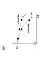
次に、上記の電池システム100において組電池制御部150が行う処理について説明する。従来の電池の充放電制御では、電池の温度やSOCを求め、これらにより推定される電池の内部抵抗値や無負荷時の電池の開回路電圧(OCV:Open Circuit Voltage)を基に、許容充放電電流や許容充放電電力を決定する方法が一般的であった。この場合の問題点について、以下の図3、4を参照して説明する。
Next, processing performed by the assembled battery control unit 150 in the battery system 100 will be described. In conventional battery charge / discharge control, the battery temperature and SOC are obtained, and the allowable charge is determined based on the estimated internal resistance of the battery and the open circuit voltage (OCV: Open Circuit Voltage) at no load. A method for determining the discharge current and the allowable charge / discharge power is common. Problems in this case will be described with reference to FIGS.
図3は、充放電時の切片電圧の変化を説明するためのグラフを示している。図3(a)のグラフは、電池の温度が比較的高温であるときの充放電電流と電池電圧の関係の一例を表している。このグラフに示すように、高温時には、充放電電流が大きくなるほど電池電圧が内部抵抗に応じた一定の割合で低下する。また、グラフ上で充放電電流を0としたときの切片電圧はOCVと略一致する。したがってこの場合、所定の使用可能電圧範囲に対応する電流の大きさをOCVと内部抵抗から求めることで、許容充放電電流や許容充放電電力を決定することができる。
FIG. 3 shows a graph for explaining the change in the intercept voltage during charging and discharging. The graph of FIG. 3A represents an example of the relationship between the charge / discharge current and the battery voltage when the battery temperature is relatively high. As shown in this graph, at high temperatures, the battery voltage decreases at a constant rate according to the internal resistance as the charge / discharge current increases. Further, the intercept voltage when the charge / discharge current is set to 0 on the graph is substantially equal to the OCV. Therefore, in this case, the allowable charge / discharge current and the allowable charge / discharge power can be determined by obtaining the magnitude of the current corresponding to the predetermined usable voltage range from the OCV and the internal resistance.
図3(b)のグラフは、電池の温度が比較的低温であるときの充放電電流と電池電圧の関係の一例を表している。このグラフに示すように、低温時には、図3(a)に示した高温時のグラフと同様に、充放電電流が大きくなるほど電池電圧が内部抵抗に応じた一定の割合で低下する。なお、低温時は高温時と比べて内部抵抗が大きくなるため、図3(b)のグラフの傾きは図3(a)よりも大きい。一方、グラフ上で充放電電流を0としたときの切片電圧は、図3(a)に示した高温時のグラフとは異なり、OCVよりも電圧V1だけ低くなる。この電圧V1は電池の温度やSOCに応じて変動し、低温になるほど、またSOCが高くなるほど、OCVに対する切片電圧の低下幅が拡大して電圧V1が大きくなる。したがってこの場合、OCVをそのまま用いて許容充放電電流や許容充放電電力を決定すると、実際よりも大きな値が求められてしまう。その結果、電池が過充電状態や過放電状態となり、安全性の低下や電池の劣化を引き起こすおそれがある。
3B represents an example of the relationship between the charge / discharge current and the battery voltage when the battery temperature is relatively low. As shown in this graph, at a low temperature, like the graph at the high temperature shown in FIG. 3A, the battery voltage decreases at a constant rate according to the internal resistance as the charge / discharge current increases. In addition, since internal resistance becomes large at the time of low temperature compared with the time of high temperature, the inclination of the graph of FIG.3 (b) is larger than Fig.3 (a). On the other hand, the intercept voltage when the charge / discharge current is 0 on the graph is lower than the OCV by the voltage V1 unlike the graph at the time of high temperature shown in FIG. This voltage V1 varies according to the temperature and SOC of the battery, and the lower the temperature and the higher the SOC, the greater the decrease in the intercept voltage with respect to the OCV and the higher the voltage V1. Therefore, in this case, if the allowable charge / discharge current and the allowable charge / discharge power are determined using the OCV as it is, a value larger than the actual value is required. As a result, the battery may be in an overcharged state or an overdischarged state, which may cause a reduction in safety or deterioration of the battery.
図4は、充放電時の内部抵抗の変化を説明するためのグラフを示している。図4において、符号41のグラフは、比較的小さな一定の放電電流で電池を放電させたときの放電時間と電池電圧の関係の一例を表している。このグラフ41に示すように、放電電流が小さいときには、放電時間の経過に伴ってSOCが一定の割合で減少すると、それに応じて電池電圧が一定の割合で低下する。これは、放電中の内部抵抗が一定であることを表している。したがってこの場合、前述の図3(a)の場合と同様に、所定の使用可能電圧範囲に対応する電流の大きさをOCVと内部抵抗から求めることで、許容充放電電流や許容充放電電力を決定することができる。
FIG. 4 shows a graph for explaining a change in internal resistance during charging and discharging. In FIG. 4, a graph denoted by reference numeral 41 represents an example of the relationship between the discharge time and the battery voltage when the battery is discharged with a relatively small constant discharge current. As shown in this graph 41, when the discharge current is small, if the SOC decreases at a constant rate as the discharge time elapses, the battery voltage decreases accordingly at a constant rate. This represents that the internal resistance during discharge is constant. Therefore, in this case, similarly to the case of FIG. 3A described above, the allowable charge / discharge current and the allowable charge / discharge power are obtained by obtaining the magnitude of the current corresponding to the predetermined usable voltage range from the OCV and the internal resistance. Can be determined.
図4において、符号42のグラフは、比較的大きな一定の放電電流で電池を放電させたときの放電時間と電池電圧の関係の一例を表している。このグラフ42に示すように、放電電流が大きいときには、放電時間の経過に伴ってSOCが一定の割合で減少すると、それに応じて電池電圧が加速度的に低下する。これは、放電中の内部抵抗が一定ではなく、放電が進むにつれて内部抵抗が徐々に大きくなることを表している。したがってこの場合、内部抵抗を一定の値として許容充放電電流や許容充放電電力を決定すると、図3(b)の場合と同様に、実際よりも大きな値が求められてしまう。その結果、電池が過充電状態や過放電状態となり、安全性の低下や電池の劣化を引き起こすおそれがある。なお、図4では放電時の例を示しているが、充電時についても同様である。
4, a graph denoted by reference numeral 42 represents an example of a relationship between a discharge time and a battery voltage when the battery is discharged with a relatively large constant discharge current. As shown in this graph 42, when the discharge current is large, if the SOC decreases at a constant rate as the discharge time elapses, the battery voltage decreases at an accelerated rate accordingly. This indicates that the internal resistance during discharge is not constant and the internal resistance gradually increases as the discharge proceeds. Therefore, in this case, if the allowable charge / discharge current and the allowable charge / discharge power are determined with the internal resistance set to a constant value, a value larger than the actual value is obtained as in the case of FIG. As a result, the battery may be in an overcharged state or an overdischarged state, which may cause a reduction in safety or deterioration of the battery. In addition, although the example at the time of discharge is shown in FIG. 4, it is the same also at the time of charge.
以上説明したような問題点を解消するため、本発明に係る電池システム100では、充放電時の組電池110の温度や充放電時間、充放電電流などを考慮して、組電池制御部150において算出した組電池110の内部抵抗や無負荷電圧を充放電状況に応じて補正する。これにより、許容充放電電流や許容充放電電力を正確に求めることができるようにしている。
In order to solve the problems as described above, in the battery system 100 according to the present invention, the battery pack controller 150 takes into account the temperature, charge / discharge time, charge / discharge current, etc. of the battery pack 110 during charge / discharge. The calculated internal resistance and no-load voltage of the assembled battery 110 are corrected according to the charge / discharge status. Thereby, the allowable charge / discharge current and the allowable charge / discharge power can be accurately obtained.
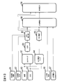
図5は、前述のような従来の充放電制御による許容値演算処理を示した制御ブロック図である。従来の充放電制御による許容値演算処理では、制御ブロック50、51において、電池測定情報から電池の温度とSOCをそれぞれ取得し、これらの値を基に、予め記憶された内部抵抗のマップ情報(DCRマップ)を制御ブロック52で参照する。DCRマップには、制御対象の電池について温度ごとのSOCと内部抵抗(DCR)の関係が記録されており、これを参照することで電池の内部抵抗を求めることができる。制御ブロック53では、制御ブロック52で行ったDCRマップの参照結果を基に、電池の内部抵抗を算出する。
FIG. 5 is a control block diagram showing an allowable value calculation process by the conventional charge / discharge control as described above. In the allowable value calculation processing by the conventional charge / discharge control, the control block 50, 51 obtains the battery temperature and SOC from the battery measurement information, respectively, and based on these values, the map information (internal resistance) stored in advance ( The DCR map) is referred to in the control block 52. In the DCR map, the relationship between the SOC and the internal resistance (DCR) for each temperature of the battery to be controlled is recorded, and the internal resistance of the battery can be obtained by referring to this. In the control block 53, the internal resistance of the battery is calculated based on the reference result of the DCR map performed in the control block 52.
一方、制御ブロック54では、制御ブロック51で取得したSOCを基に、予め記憶されたOCVのマップ情報(OCVマップ)を参照する。OCVマップには、制御対象の電池についてSOCとOCVの関係が記録されており、これを参照することで電池のOCVを求めることができる。制御ブロック55では、制御ブロック52で行ったOCVマップの参照結果を基に、電池のOCVを算出する。
On the other hand, the control block 54 refers to the OCV map information (OCV map) stored in advance based on the SOC acquired in the control block 51. In the OCV map, the relationship between the SOC and the OCV is recorded for the battery to be controlled, and the OCV of the battery can be obtained by referring to this. In the control block 55, the OCV of the battery is calculated based on the reference result of the OCV map performed in the control block 52.
制御ブロック56、57では、予め設定された電池の上下限電圧と上限電流をそれぞれ取得する。制御ブロック58では、これらの値と、制御ブロック53、55でそれぞれ算出した内部抵抗およびOCVとに基づいて、充放電時における電池の許容電流、すなわち許容充放電電流を算出する。制御ブロック59では、制御ブロック58で行った許容充放電電流の算出結果と、制御ブロック53、55でそれぞれ算出した内部抵抗およびOCVとに基づいて、充放電時における電池の許容電力、すなわち許容充放電電力を算出する。
In the control blocks 56 and 57, the upper and lower limit voltages and the upper limit current set in advance are respectively acquired. In the control block 58, based on these values and the internal resistance and OCV calculated in the control blocks 53 and 55, the allowable current of the battery at the time of charging / discharging, that is, the allowable charging / discharging current is calculated. In the control block 59, based on the calculation result of the allowable charging / discharging current performed in the control block 58 and the internal resistance and OCV calculated in the control blocks 53, 55, the allowable power of the battery at the time of charging / discharging, that is, the allowable charging / discharging. Discharge power is calculated.
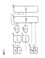
図6は、本発明の充放電制御による許容値演算処理を示した制御ブロック図である。この制御ブロック図は、図5に示した従来の充放電制御による許容値演算処理の制御ブロック図と比べて、制御ブロック61、62および63を有する点と、制御ブロック54、55が制御ブロック64、65にそれぞれ置き換えられている点が異なっている。
FIG. 6 is a control block diagram showing an allowable value calculation process by charge / discharge control of the present invention. This control block diagram is different from the control block diagram of the allowable value calculation processing by the conventional charge / discharge control shown in FIG. , 65 are different from each other.
本発明の充放電制御による許容値演算処理では、制御ブロック61、62において、電池の充放電時間と充放電電流をそれぞれ取得し、これらの値を基に、制御ブロック53で算出した内部抵抗を制御ブロック63で補正する。また、制御ブロック64では、制御ブロック50、51でそれぞれ取得した温度とSOCを基に、予め記憶された切片電圧のマップ情報(切片電圧マップ)を参照する。切片電圧マップには、制御対象の電池について充放電時間および充放電電流と図3で説明した切片電圧との関係が記録されており、これを参照することで前述のような切片電圧を求めることができる。制御ブロック65では、制御ブロック64で行った切片電圧マップの参照結果を基に、電池の切片電圧を算出する。この切片電圧をOCVの代わりに用いることで、電池の無負荷電圧をOCVから切片電圧に補正する。
In the allowable value calculation processing by the charge / discharge control of the present invention, the control blocks 61 and 62 obtain the charge / discharge time and charge / discharge current of the battery, respectively, and the internal resistance calculated by the control block 53 is calculated based on these values. Correction is performed by the control block 63. Further, the control block 64 refers to the pre-stored map information of the intercept voltage (intercept voltage map) based on the temperature and the SOC acquired by the control blocks 50 and 51, respectively. In the intercept voltage map, the relationship between the charge / discharge time and charge / discharge current and the intercept voltage described in FIG. 3 is recorded for the battery to be controlled, and the intercept voltage as described above is obtained by referring to this. Can do. In the control block 65, the intercept voltage of the battery is calculated based on the reference result of the intercept voltage map performed in the control block 64. By using this intercept voltage instead of the OCV, the no-load voltage of the battery is corrected from the OCV to the intercept voltage.
制御ブロック58、59では、制御ブロック56、57でそれぞれ取得した上下限電圧および上限電流と、制御ブロック63で補正した内部抵抗と、制御ブロック65でOCVに代えて算出した切片電圧とに基づいて、充放電時における電池の許容電流および許容電力を算出する。これにより、電池の充放電状況に応じた許容充放電電流および許容充放電電力を算出する。
In the control blocks 58 and 59, based on the upper and lower limit voltages and the upper limit current acquired in the control blocks 56 and 57, the internal resistance corrected in the control block 63, and the intercept voltage calculated in place of the OCV in the control block 65, respectively. The allowable current and allowable power of the battery at the time of charging / discharging are calculated. Thereby, the allowable charge / discharge current and the allowable charge / discharge power according to the charge / discharge status of the battery are calculated.
図7は、上記で説明したような本発明の充放電制御による許容値演算処理の手順を示したフローチャートである。組電池制御部150は、このフローチャートに従って許容値演算処理を実行する。
FIG. 7 is a flowchart showing a procedure of an allowable value calculation process by charge / discharge control of the present invention as described above. The assembled battery control unit 150 executes an allowable value calculation process according to this flowchart.
組電池制御部150は、ステップ1101において、取得部150aにより、単電池管理部120、電流検知部130および電圧検知部140から電池測定情報を取得する。すなわち、単電池管理部120からは電池電圧および温度の情報を、電流検知部130からは充放電電流の情報を、電圧検知部140からの総電圧の情報を、電池測定情報としてそれぞれ取得する。
In step 1101, the assembled battery control unit 150 acquires battery measurement information from the single cell management unit 120, the current detection unit 130, and the voltage detection unit 140 by the acquisition unit 150 a. That is, the battery voltage and temperature information is acquired from the single cell management unit 120, the charge / discharge current information is acquired from the current detection unit 130, and the total voltage information from the voltage detection unit 140 is acquired as battery measurement information.
組電池制御部150は、ステップ1102において、時間計測部150bにより、充放電時間を計測する。ここでは、充電中であれば充電継続時間を、放電中であれば放電継続時間を、充放電時間としてそれぞれ計測する。
In step 1102, the assembled battery control unit 150 measures the charge / discharge time by the time measurement unit 150b. Here, the charging duration is measured as charging / discharging time when charging, and the discharging duration is measured when discharging, respectively.
組電池制御部150は、ステップ1103において、SOC算出部150cにより、SOCの算出を行う。ここでは、たとえばステップ1101で取得した電池測定情報に含まれる充放電電流を積算することで、組電池110に蓄積されている電力量の変化量を求める。こうして求めた電力量の変化量に基づいて、組電池110における現在の蓄積電力量を推定することで、SOCを算出することができる。なお、これ以外の方法でSOCを算出してもよい。
In step 1103, the assembled battery control unit 150 calculates the SOC by the SOC calculation unit 150c. Here, for example, the amount of change in the electric energy stored in the assembled battery 110 is obtained by integrating the charge / discharge current included in the battery measurement information acquired in step 1101. The SOC can be calculated by estimating the current stored power amount in the assembled battery 110 based on the change amount of the power amount thus obtained. Note that the SOC may be calculated by other methods.
組電池制御部150は、ステップ1104において、内部抵抗算出部150dにより、内部抵抗(DCR)を算出する。ここでは、記憶部180に記憶されているDCRマップを参照し、ステップ1101で電池測定情報として取得した温度と、ステップ1103で算出したSOCとに該当する内部抵抗の値をDCRマップから検索する。これにより、組電池110の特性に応じた内部抵抗を温度とSOCから正確に算出することができる。
In step 1104, the assembled battery control unit 150 calculates the internal resistance (DCR) by the internal resistance calculation unit 150d. Here, the DCR map stored in the storage unit 180 is referred to, and the internal resistance value corresponding to the temperature acquired as the battery measurement information in step 1101 and the SOC calculated in step 1103 is searched from the DCR map. Thereby, the internal resistance according to the characteristics of the assembled battery 110 can be accurately calculated from the temperature and the SOC.
組電池制御部150は、ステップ1105において、補正部150eにより、ステップ1104で算出した内部抵抗(DCR)を補正する。ここでは、ステップ1102で計測した充放電時間と、ステップ1101で電池測定情報として取得した充放電電流とに基づいて、内部抵抗に対する補正係数を決定する。たとえば、図4で説明したような充放電時の電池電圧の変化を反映した補正係数マップを記憶部180に予め記憶しておき、これを参照することで、充放電時間および充放電電流に応じた補正係数を決定する。そして、ステップ1104で算出した内部抵抗に対してこの補正係数を掛けることで、充放電時間および充放電電流に応じた内部抵抗の補正値を求めることができる。または、図4で説明したような充放電時の電池電圧の変化を基に、充放電時間と充放電電流を変数とする補正係数の関数を定義しておき、これを用いることで補正係数を決定して内部抵抗を補正してもよい。
In step 1105, the assembled battery control unit 150 corrects the internal resistance (DCR) calculated in step 1104 by the correction unit 150e. Here, a correction coefficient for the internal resistance is determined based on the charge / discharge time measured in step 1102 and the charge / discharge current acquired as battery measurement information in step 1101. For example, a correction coefficient map reflecting changes in battery voltage during charging / discharging as described in FIG. 4 is stored in advance in the storage unit 180, and is referred to according to the charging / discharging time and charging / discharging current. Determine the correction factor. Then, by multiplying the internal resistance calculated in step 1104 by this correction coefficient, it is possible to obtain a correction value of the internal resistance according to the charge / discharge time and the charge / discharge current. Alternatively, based on the change in battery voltage during charging / discharging as described in FIG. 4, a function of a correction coefficient having charging / discharging time and charging / discharging current as variables is defined, and the correction coefficient is determined by using this function. The internal resistance may be corrected by determining.
なお、図4のグラフ42に示したような電池電圧の変化は、電池の温度が所定値以上であるときに顕著に表れる。この点を踏まえて、ステップ1101で電池測定情報として取得した温度が所定値未満の場合には、ステップ1105の処理を省略して内部抵抗の補正を行わないようにしてもよい。
It should be noted that the change in the battery voltage as shown in the graph 42 in FIG. 4 is noticeable when the battery temperature is equal to or higher than a predetermined value. In consideration of this point, when the temperature acquired as the battery measurement information in step 1101 is less than a predetermined value, the processing in step 1105 may be omitted so that the internal resistance is not corrected.
組電池制御部150は、ステップ1106において、切片電圧算出部150fにより、図3で説明したような切片電圧を算出する。ここでは、記憶部180に記憶されている切片電圧マップを参照し、ステップ1101で電池測定情報として取得した温度と、ステップ1103で算出したSOCとに該当する切片電圧の値を切片電圧マップから検索する。これにより、組電池110の特性に応じた切片電圧を温度とSOCから正確に算出することができる。または、温度とSOCを変数とする切片電圧の関数を定義しておき、これを用いることで切片電圧を算出してもよい。
In step 1106, the assembled battery control unit 150 calculates the intercept voltage as described with reference to FIG. Here, the intercept voltage map stored in the storage unit 180 is referenced, and the intercept voltage value corresponding to the temperature acquired as the battery measurement information in step 1101 and the SOC calculated in step 1103 is searched from the intercept voltage map. To do. Thereby, the intercept voltage according to the characteristic of the assembled battery 110 can be accurately calculated from the temperature and the SOC. Alternatively, the intercept voltage may be calculated by defining a function of the intercept voltage using the temperature and SOC as variables and using this function.
組電池制御部150は、ステップ1107において、許容値算出部150gにより、許容充放電電流の候補値Iを算出する。ここでは、ステップ1105で補正した内部抵抗の値と、ステップ1106で算出した切片電圧の値と、記憶部180に予め記憶されている下限電圧とを用いて、以下の式(1)により許容充放電電流の候補値Iを算出する。たとえば2.0~4.2Vの範囲で使用可能なリチウムイオン電池の場合、2.0Vが下限電圧として記憶部180に記憶されている。
I=(切片電圧-下限電圧)/補正後の内部抵抗 ・・・(1)
In step 1107, the assembled battery control unit 150 calculates the allowable charge / discharge current candidate value I by the allowable value calculation unit 150g. Here, using the value of the internal resistance corrected in step 1105, the value of the intercept voltage calculated in step 1106, and the lower limit voltage stored in advance in the storage unit 180, an allowable charge is obtained by the following equation (1). A discharge current candidate value I is calculated. For example, in the case of a lithium ion battery that can be used in the range of 2.0 to 4.2 V, 2.0 V is stored in the storage unit 180 as the lower limit voltage.
I = (intercept voltage−lower limit voltage) / corrected internal resistance (1)
組電池制御部150は、ステップ1108において、許容値算出部150gにより、ステップ1107で算出した許容充放電電流の候補値Iが所定の上限電流よりも大きいか否かを判定する。この上限電流は、充放電時における安全性等を考慮した値が記憶部180に予め記憶されている。
In step 1108, the assembled battery control unit 150 determines whether the allowable charge / discharge current candidate value I calculated in step 1107 is larger than a predetermined upper limit current by the allowable value calculation unit 150g. The upper limit current is stored in advance in the storage unit 180 in consideration of safety during charging and discharging.
ステップ1108で許容充放電電流の候補値Iが上限電流よりも大きいと判定した場合、組電池制御部150はステップ1109において、許容充放電電流を上限電流に設定する。一方、許容充放電電流の候補値Iが上限電流以下であると判定した場合、組電池制御部150はステップ1110において、その候補値Iを許容充放電電流とする。ステップ1109または1110を実行したら、ステップ1111へ進む。
When it is determined in step 1108 that the allowable charge / discharge current candidate value I is larger than the upper limit current, the assembled battery control unit 150 sets the allowable charge / discharge current to the upper limit current in step 1109. On the other hand, when it determines with the candidate value I of allowable charging / discharging current being below an upper limit electric current, the assembled battery control part 150 makes the candidate value I the allowable charging / discharging current in step 1110. When step 1109 or 1110 is executed, the process proceeds to step 1111.
組電池制御部150は、ステップ1111において、許容値算出部150gにより、許容充放電電力を算出する。ここでは、ステップ1105で補正した内部抵抗の値と、ステップ1106で算出した切片電圧の値と、ステップ1109またはステップ1110で設定した許容充放電電流とを用いて、以下の式(2)により許容充放電電力を算出する。
許容充放電電力=許容充放電電流×
(切片電圧+許容充放電電流×補正後の内部抵抗) ・・・(2)
In step 1111, the assembled battery control unit 150 calculates the allowable charge / discharge power by the allowable value calculation unit 150g. Here, using the internal resistance value corrected in step 1105, the intercept voltage value calculated in step 1106, and the allowable charge / discharge current set in step 1109 or step 1110, the following equation (2) allows Charge / discharge power is calculated.
Allowable charge / discharge power = Allowable charge / discharge current x
(Intercept voltage + allowable charge / discharge current x internal resistance after correction) (2)
ステップ1111を実行したら、組電池制御部150は図7のフローチャートによる許容値演算処理を終了する。そして、許容充放電電流および許容充放電電力の各算出結果を、単電池管理部120や車両制御部200に送信する。
If step 1111 is performed, the assembled battery control part 150 complete | finishes the tolerance calculation process by the flowchart of FIG. And each calculation result of allowable charging / discharging electric current and allowable charging / discharging electric power is transmitted to the cell management part 120 and the vehicle control part 200. FIG.
続いて、本発明による許容値演算処理の確認方法について説明する。ここでは、組電池制御部150から送信される許容充放電電流または許容充放電電力を基に、本発明による許容値演算処理が組電池制御部150において行われているか否かを確認する方法について説明する。なお、以下の説明では、組電池制御部150を専用の試験装置等に接続することで、許容充放電電流および許容充放電電力に加えて、さらにSOCの算出結果を組電池制御部150から取得できる場合を想定する。
Subsequently, a method for confirming the allowable value calculation processing according to the present invention will be described. Here, a method for confirming whether or not an allowable value calculation process according to the present invention is performed in the assembled battery control unit 150 based on the allowable charge / discharge current or the allowable charge / discharge power transmitted from the assembled battery control unit 150. explain. In the following description, by connecting the assembled battery control unit 150 to a dedicated test device or the like, in addition to the allowable charge / discharge current and the allowable charge / discharge power, the calculation result of the SOC is further acquired from the assembled battery control unit 150. Assume when possible.
確認者は、組電池制御部150から取得したSOCの算出結果と、既知である前述のOCVマップやDCRマップの内容に基づいて、組電池110のOCVおよび内部抵抗を計算し、許容充放電電流または許容充放電電力を計算する。そして、計算されたこれらの値と、組電池制御部150から取得した許容充放電電流または許容充放電電力の値とを比較する。その結果、両者の値が一致していなければ、本発明による許容値演算処理が組電池制御部150において実行されており、OCVの代わりに切片電圧を用いている可能性があると判断することができる。なお、上記の値の差は低温時において特に顕著となるため、所定の温度以下で確認することが好ましい。
The confirmer calculates the OCV and internal resistance of the assembled battery 110 based on the calculation result of the SOC acquired from the assembled battery control unit 150 and the contents of the known OCV map and DCR map, and the allowable charge / discharge current. Alternatively, the allowable charge / discharge power is calculated. Then, these calculated values are compared with the value of the allowable charge / discharge current or the allowable charge / discharge power acquired from the assembled battery control unit 150. As a result, if the two values do not match, it is determined that the allowable value calculation processing according to the present invention is executed in the assembled battery control unit 150, and there is a possibility that the intercept voltage may be used instead of the OCV. Can do. In addition, since the difference of said value becomes remarkable especially at low temperature, it is preferable to confirm below below predetermined temperature.
また確認者は、組電池110を連続的に充放電させたときに、組電池制御部150から取得したSOCの算出結果に基づいて計算した内部抵抗の値の変化の様子を観察する。その結果、充放電時間の経過に応じて内部抵抗の値が次第に増加する場合は、本発明による許容値演算処理が組電池制御部150において実行されており、充放電時間および充放電電流に基づいて内部抵抗を補正している可能性があると判断することができる。なお、上記の内部抵抗の変化は充放電電流が大きいときに特に顕著となるため、一定の充放電電流以上で確認することが好ましい。
The confirmer observes the state of change in the value of the internal resistance calculated based on the calculation result of the SOC acquired from the assembled battery control unit 150 when the assembled battery 110 is continuously charged and discharged. As a result, when the value of the internal resistance gradually increases as the charge / discharge time elapses, the allowable value calculation processing according to the present invention is executed in the assembled battery control unit 150, and is based on the charge / discharge time and the charge / discharge current. Therefore, it can be determined that the internal resistance may be corrected. In addition, since the change of said internal resistance becomes remarkable especially when charging / discharging electric current is large, it is preferable to confirm with more than fixed charging / discharging electric current.
以上説明した実施の形態によれば、次の作用効果を奏する。
According to the embodiment described above, the following operational effects are obtained.
(1)組電池制御部150は、組電池110の無負荷電圧および内部抵抗から、組電池110の充放電時における許容電流および許容電力を算出する。このとき、組電池110の充放電の状況に応じて、無負荷電圧および内部抵抗を補正する。このようにしたので、充放電時に許容される電流や電力を正確に求めることができる。
(1) The assembled battery control unit 150 calculates the allowable current and allowable power during charging / discharging of the assembled battery 110 from the no-load voltage and the internal resistance of the assembled battery 110. At this time, the no-load voltage and the internal resistance are corrected according to the charge / discharge status of the assembled battery 110. Since it did in this way, the electric current and electric power which are accept | permitted at the time of charging / discharging can be calculated | required correctly.
(2)組電池制御部150は、取得部150aにより組電池110の温度を取得し(ステップ1101)、SOC算出部150cにより組電池110のSOCを算出する(ステップ1103)。これらの温度とSOCとに基づいて、切片電圧算出部150fにより、組電池110の充放電電流と組電池110の電圧との関係を表すグラフにおいて充放電電流が0であるときの切片電圧を算出する(ステップ1106)。こうして算出された切片電圧を、OCVに替えて組電池110の充放電時における許容電流および許容電力の算出に用いられる無負荷電圧とすることで、無負荷電圧を補正するようにした。これにより、充放電時の切片電圧の変化を反映して、無負荷電圧を正しく補正することができる。
(2) The assembled battery control unit 150 acquires the temperature of the assembled battery 110 by the acquisition unit 150a (step 1101), and calculates the SOC of the assembled battery 110 by the SOC calculation unit 150c (step 1103). Based on these temperatures and SOC, the intercept voltage calculation unit 150f calculates the intercept voltage when the charge / discharge current is 0 in the graph representing the relationship between the charge / discharge current of the assembled battery 110 and the voltage of the assembled battery 110. (Step 1106). The intercept voltage calculated in this way is changed to the no-load voltage used for calculating the allowable current and the allowable power during charging / discharging of the assembled battery 110 instead of the OCV, thereby correcting the no-load voltage. As a result, the no-load voltage can be corrected correctly reflecting the change in the intercept voltage during charging and discharging.
(3)切片電圧算出部150fは、記憶部180に予め記憶された切片電圧マップを参照して、取得部150aで取得した温度およびSOC算出部150cで算出したSOCに対応する切片電圧を算出する。このようにしたので、組電池110の特性に応じた切片電圧を正確に算出することができる。
(3) The intercept voltage calculation unit 150f refers to the intercept voltage map stored in advance in the storage unit 180, and calculates the intercept voltage corresponding to the temperature acquired by the acquisition unit 150a and the SOC calculated by the SOC calculation unit 150c. . Since it did in this way, the intercept voltage according to the characteristic of the assembled battery 110 can be calculated correctly.
(4)組電池制御部150は、取得部150aにより組電池110の充放電電流を取得し(ステップ1101)、時間計測部150bにより組電池110の充放電時間を計測し(ステップ1102)、内部抵抗算出部150dにより組電池110の内部抵抗を算出する(ステップ1104)。そして、補正部150eにより、上記の内部抵抗を充放電時間および充放電電流に基づいて補正する(ステップ1105)。このようにしたので、充放電時の内部抵抗の変化を反映して、内部抵抗を正しく補正することができる。
(4) The assembled battery control unit 150 acquires the charging / discharging current of the assembled battery 110 by the acquiring unit 150a (step 1101), measures the charging / discharging time of the assembled battery 110 by the time measuring unit 150b (step 1102), and The internal resistance of the assembled battery 110 is calculated by the resistance calculation unit 150d (step 1104). The correction unit 150e corrects the internal resistance based on the charge / discharge time and the charge / discharge current (step 1105). Since it did in this way, internal resistance can be correct | amended correctly reflecting the change of internal resistance at the time of charging / discharging.
(5)補正部150eは、取得部150aで取得した温度が所定値未満の場合、内部抵抗の補正を行わないこととしてもよい。このようにすれば、充放電時に内部抵抗の変化が現れないような温度範囲では、不要な処理を省略することができる。
(5) The correction unit 150e may not correct the internal resistance when the temperature acquired by the acquisition unit 150a is lower than a predetermined value. In this way, unnecessary processing can be omitted in a temperature range in which a change in internal resistance does not appear during charging and discharging.
(6)補正部150eは、記憶部180に予め記憶された補正係数マップを参照して、充放電時間および充放電電流に対応する内部抵抗の補正値を求めることができる。このようにすれば、組電池110の特性に応じて内部抵抗を正確に補正することができる。
(6) The correction unit 150e can obtain the correction value of the internal resistance corresponding to the charge / discharge time and the charge / discharge current with reference to the correction coefficient map stored in the storage unit 180 in advance. In this way, the internal resistance can be accurately corrected according to the characteristics of the assembled battery 110.
なお、本発明は上述した実施形態に限定されるものではなく、本発明の趣旨を逸脱しない範囲で種々の設計変更が可能である。たとえば、上記実施形態では、各種のマップ情報を参照することにより、組電池110の内部抵抗や切片電圧を算出したり、内部抵抗の補正係数を算出したりする例を説明したが、これらの算出は必ずしもマップ情報を参照して行わなくてもよい。
The present invention is not limited to the above-described embodiment, and various design changes can be made without departing from the spirit of the present invention. For example, in the above embodiment, an example in which the internal resistance and intercept voltage of the assembled battery 110 are calculated or the correction coefficient of the internal resistance is calculated by referring to various types of map information has been described. Is not necessarily performed with reference to the map information.
また、上記実施の形態において、許容充放電電流または許容充放電電力のいずれか一方の算出を省略してもよい。さらに、切片電圧算出部150fによる切片電圧の算出と、補正部150eによる内部抵抗の補正とのいずれか一方の処理を省略してもよい。なお、切片電圧の算出を省略する場合は、切片電圧の代わりにOCVを算出し、これを用いて許容充放電電流や許容充放電電力を算出すればよい。すなわち本発明は、無負荷電圧および内部抵抗から電池の充放電時における許容電流および許容電力の少なくとも一つを算出する電池制御装置に適用可能であり、電池の充放電の状況に応じて無負荷電圧および内部抵抗の少なくとも一つを補正するものである。
In the above embodiment, calculation of either the allowable charge / discharge current or the allowable charge / discharge power may be omitted. Furthermore, either the processing of the intercept voltage calculation by the intercept voltage calculation unit 150f or the correction of the internal resistance by the correction unit 150e may be omitted. In the case where the calculation of the intercept voltage is omitted, the OCV may be calculated instead of the intercept voltage, and the allowable charge / discharge current and the allowable charge / discharge power may be calculated using this. That is, the present invention can be applied to a battery control device that calculates at least one of allowable current and allowable power during charging / discharging of a battery from no-load voltage and internal resistance. It corrects at least one of voltage and internal resistance.
以上説明したような各種の変形例は、それぞれ単独で適用しても、任意に組み合わせて適用してもよい。
The various modifications described above may be applied individually or in any combination.
以上説明した実施形態や各種の変形例はあくまで一例であり、発明の特徴が損なわれない限り、本発明はこれらの内容に限定されるものではない。
The embodiments and various modifications described above are merely examples, and the present invention is not limited to these contents as long as the features of the invention are not impaired.