WO2013161410A1 - インクジェット記録用インク組成物、インク供給システム及びインクジェット記録装置 - Google Patents
インクジェット記録用インク組成物、インク供給システム及びインクジェット記録装置 Download PDFInfo
- Publication number
- WO2013161410A1 WO2013161410A1 PCT/JP2013/056813 JP2013056813W WO2013161410A1 WO 2013161410 A1 WO2013161410 A1 WO 2013161410A1 JP 2013056813 W JP2013056813 W JP 2013056813W WO 2013161410 A1 WO2013161410 A1 WO 2013161410A1
- Authority
- WO
- WIPO (PCT)
- Prior art keywords
- ink
- carbon atoms
- main chain
- acetylene glycol
- head
- Prior art date
Links
Images


Classifications
-
- C—CHEMISTRY; METALLURGY
- C09—DYES; PAINTS; POLISHES; NATURAL RESINS; ADHESIVES; COMPOSITIONS NOT OTHERWISE PROVIDED FOR; APPLICATIONS OF MATERIALS NOT OTHERWISE PROVIDED FOR
- C09D—COATING COMPOSITIONS, e.g. PAINTS, VARNISHES OR LACQUERS; FILLING PASTES; CHEMICAL PAINT OR INK REMOVERS; INKS; CORRECTING FLUIDS; WOODSTAINS; PASTES OR SOLIDS FOR COLOURING OR PRINTING; USE OF MATERIALS THEREFOR
- C09D11/00—Inks
- C09D11/30—Inkjet printing inks
- C09D11/38—Inkjet printing inks characterised by non-macromolecular additives other than solvents, pigments or dyes
-
- B—PERFORMING OPERATIONS; TRANSPORTING
- B41—PRINTING; LINING MACHINES; TYPEWRITERS; STAMPS
- B41J—TYPEWRITERS; SELECTIVE PRINTING MECHANISMS, i.e. MECHANISMS PRINTING OTHERWISE THAN FROM A FORME; CORRECTION OF TYPOGRAPHICAL ERRORS
- B41J2/00—Typewriters or selective printing mechanisms characterised by the printing or marking process for which they are designed
- B41J2/005—Typewriters or selective printing mechanisms characterised by the printing or marking process for which they are designed characterised by bringing liquid or particles selectively into contact with a printing material
- B41J2/01—Ink jet
- B41J2/17—Ink jet characterised by ink handling
- B41J2/175—Ink supply systems ; Circuit parts therefor
- B41J2/17563—Ink filters
-
- B—PERFORMING OPERATIONS; TRANSPORTING
- B41—PRINTING; LINING MACHINES; TYPEWRITERS; STAMPS
- B41J—TYPEWRITERS; SELECTIVE PRINTING MECHANISMS, i.e. MECHANISMS PRINTING OTHERWISE THAN FROM A FORME; CORRECTION OF TYPOGRAPHICAL ERRORS
- B41J2/00—Typewriters or selective printing mechanisms characterised by the printing or marking process for which they are designed
- B41J2/005—Typewriters or selective printing mechanisms characterised by the printing or marking process for which they are designed characterised by bringing liquid or particles selectively into contact with a printing material
- B41J2/01—Ink jet
- B41J2/21—Ink jet for multi-colour printing
- B41J2/2107—Ink jet for multi-colour printing characterised by the ink properties
-
- C—CHEMISTRY; METALLURGY
- C09—DYES; PAINTS; POLISHES; NATURAL RESINS; ADHESIVES; COMPOSITIONS NOT OTHERWISE PROVIDED FOR; APPLICATIONS OF MATERIALS NOT OTHERWISE PROVIDED FOR
- C09D—COATING COMPOSITIONS, e.g. PAINTS, VARNISHES OR LACQUERS; FILLING PASTES; CHEMICAL PAINT OR INK REMOVERS; INKS; CORRECTING FLUIDS; WOODSTAINS; PASTES OR SOLIDS FOR COLOURING OR PRINTING; USE OF MATERIALS THEREFOR
- C09D11/00—Inks
- C09D11/30—Inkjet printing inks
Definitions
- the present invention relates to an ink composition for inkjet recording.
- the present invention also relates to an ink supply system and an ink jet recording apparatus including the ink supply system.
- a printing method using an ink jet recording method is performed by ejecting and ejecting small ink droplets from a print head and depositing them on a recording medium such as paper.
- a recording medium such as paper.
- ejecting ink ejection defects tend to occur due to bubbles generated in the ink. Therefore, various techniques for removing bubbles and stably ejecting ink by degassing ink using a deaeration device have been proposed.
- Patent Document 1 discloses a reactive water-soluble dye (CI Reactive Blue 72) 13% by mass, ion-exchanged water 60% by mass, ethylene glycol 23.7% by mass, a surfactant (Olfin E1010: acetylene glycol-based interface).
- the ink tank includes a liquid injection path (hereinafter, also referred to as “ink filling port” or “liquid injection section”), and the user can easily access the liquid injection path. Ink can be injected.
- a liquid injection path hereinafter, also referred to as “ink filling port” or “liquid injection section”
- an ink jet recording apparatus provided with an ink container that can contact ink with the atmosphere, such as an open ink cartridge. Even in the case where ink is supplied to the print head in this ink jet recording apparatus, there is a problem that ink containing bubbles is carried to the print head, resulting in poor filling and ejection in the print head. Such poor filling and ejection in the print head leads to deterioration of initial filling property and continuous printing stability.
- a first object of the present invention is to provide an ink composition that is hardly degassed (for example, the amount of dissolved nitrogen is 5 ppm or more) or an ink composition that is not degassed at all (for example, the amount of dissolved nitrogen is 7 ppm or more). Even so, it is to provide an ink composition for inkjet recording excellent in initial filling property and continuous printing stability.
- the second object of the present invention is excellent in at least one of the initial filling property and the continuous printing stability, even in the case of ink containing bubbles, which is contained in an ink containing container that can come into contact with the atmosphere.
- An ink supply system and an inkjet recording apparatus are provided.
- an object of the present invention is to achieve at least one of the aforementioned first or second objects.
- an ink composition for inkjet recording comprising an alkylene oxide adduct of acetylene glycol having a main chain having 12 or more carbon atoms, an acetylene glycol having a main chain having 10 or more carbon atoms, and a polyoxyalkylene alkyl ether.
- the present invention found that the above problems could be solved, and completed the first invention (Embodiment A).
- the present inventors set the composition of ink supplied from the ink container to the print head (including “replenishment”; the same applies hereinafter).
- the present invention (embodiment B) has been completed by finding that the above-mentioned problems can be solved by an ink supply system that is provided with a filter in an ink supply path that connects the ink container and the print head. .
- A alkylene oxide adduct of acetylene glycol having 12 or more carbon atoms in the main chain
- Acetylene glycol (B) having 10 or more carbon atoms in the main chain
- An ink composition for ink-jet recording comprising polyoxyalkylene alkyl ether (C).
- C polyoxyalkylene alkyl ether
- the ink composition for inkjet recording according to [1], wherein the alkylene oxide adduct is an ethylene oxide adduct.
- [4] The content of polyoxyalkylene alkyl ether (C), the alkylene oxide adduct (A) of acetylene glycol having 12 or more carbon atoms in the main chain, and the acetylene glycol (B) having 10 or more carbon atoms in the main chain
- [5] The ink composition for ink jet recording according to [1], wherein the alkylene oxide adduct (A) of acetylene glycol having 12 or more carbon atoms in the main chain has an HLB value of 8 to 15.
- An ink storage container for storing the ink according to [1], which is capable of contacting the air and the ink;
- a print head for ejecting the ink;
- An ink supply path that connects the ink container and the print head, and the ink flows from the ink container to the print head;
- An ink supply system comprising: a filter (D) provided in the ink supply path.
- a filter (D) provided in the ink supply path.
- FIG. 1 is a block diagram illustrating an overall configuration of a printer including an ink supply system. It is the schematic which shows the cross section of the printer provided with the ink supply system.
- FIG. 6 is a schematic diagram for explaining the principle of ink supply from an ink tank, which is an example of an ink container, to a head.
- the ink composition includes an alkylene oxide adduct (A) of acetylene glycol having a main chain having 12 or more carbon atoms, an acetylene glycol (B) having a main chain having 10 or more carbon atoms, and a polyoxyalkylene alkyl ether. (C).
- A alkylene oxide adduct
- B acetylene glycol
- C polyoxyalkylene alkyl ether
- the ink composition of Embodiment A includes an alkylene oxide adduct (A) of acetylene glycol having a main chain having 12 or more carbon atoms (hereinafter, the alkylene oxide adduct is also referred to as “AO adduct”).
- the AO adduct of acetylene glycol having 12 or more carbon atoms in the main chain is included in the acetylene glycol surfactant together with acetylene glycol having 10 or more carbon atoms in the main chain described later.
- “main chain” means a main chain based on the IUPAC nomenclature.
- the above acetylene glycol surfactant belongs to the nonionic surfactant.
- the nonionic surfactant has an action of spreading the ink uniformly on the recording medium. Therefore, when ink jet recording is performed using an ink composition containing a nonionic surfactant, a relatively high-definition image with little bleeding can be obtained.
- acetylene glycol surfactants those having 12 or more carbon atoms in the main chain have high wettability with respect to foreign substances that can contribute to the generation of bubbles in the polymer member such as rubber and plastic constituting the ink flow path and ink. By making it excellent, it is possible to suppress the generated bubbles from remaining on the flow path surface of the polymer member from the ink tank to the head. As a result, the initial filling property is excellent, and the growth of the remaining bubbles and the dot omission due to the separation of the bubbles adhering to the flow path surface can be prevented, so that the continuous printing stability is improved.
- Acetylene glycol having 12 or more carbon atoms in the main chain may not be stably dissolved (dispersed) in water-based ink containing water as a solvent.
- an AO adduct of acetylene glycol having 12 or more carbon atoms in the main chain is excellent in solubility in the aqueous ink.
- the above matters have been described for the case where the ink composition of Embodiment A contains an acetylene glycol having a main chain of 12 or more carbon atoms instead of an AO adduct of acetylene glycol having a main chain of 12 or more carbon atoms.
- the acetylene glycol having 10 or more carbon atoms in the main chain which will be described later, has nothing to do with 12 or more carbon atoms. That is, when the ink composition of Embodiment A includes an AO adduct of acetylene glycol having 12 or more carbon atoms in the main chain and an acetylene glycol having 10 or more carbon atoms in the main chain, those having 12 or more carbon atoms. The solubility in these water-based inks is excellent.
- the HLB (Hydrophile®-Lipophile® Balance) value of the acetylene glycol AO adduct having a main chain carbon number of 12 or more is preferably 8 to 15 because the above-mentioned wettability is further improved.
- the HLB value in this specification is an HLB value defined by the Griffin method.
- the AO adduct of acetylene glycol having 12 or more carbon atoms in the main chain is not limited to the following, and examples thereof include acetylated acetylene glycol represented by the following general formula (1).
- R 1 , R 1 ′ , R 2 , and R 2 ′ each independently represent an alkyl group having 1 to 5 carbon atoms, the main chain has 12 or more carbon atoms, —OR 3 represents —OH or —O (C 2 H 4 O) m H, and —OR 3 ′ represents —OH or —O (C 2 H 4 O) n H.
- m and n are values including a decimal number of 0.5 to 25 independently of each other, and m + n is a value including a decimal number of 1 to 40 (provided that -OR 3 and -OR 3 ' are both- Except when it is OH).
- AO adduct of acetylene glycol having 12 or more carbon atoms in the main chain include, but are not limited to, ethoxylates of 2,5,8,11-tetramethyl-6-dodecin-5,8-diol, and An ethoxylated product of 5,8-dimethyl-6-dodecine-5,8-diol is preferred.
- alkylene oxide adducts of acetylene glycol ethylene oxide adduct of acetylene glycol and propylene oxide adduct of acetylene glycol are preferable, and ethylene oxide adduct of acetylene glycol is more preferable.
- the number of moles of ethylene oxide units added in acetylene glycol is preferably 1 to 20 moles for each of R3 and R3 ′, and the total number of moles added (total of R3 and R3 ′) is 2 to 40 moles. It is preferable that When the total number of added moles of ethylene oxide is 40 moles or less, static and dynamic surface tension can be reduced, and ink absorption performance is improved.
- a commercial product of an AO adduct of acetylene glycol having 12 or more carbon atoms in the main chain is not limited to the following.
- Olfin EXP4300 (trade name, manufactured by Nissin Chemical Industry CO., Ltd.) C12, ethylene oxide adduct).
- the AO adduct of acetylene glycol having 12 or more carbon atoms in the main chain may be used alone or in combination of two or more.
- the content of the AO adduct of acetylene glycol having 12 or more carbon atoms in the main chain preferably takes into account the sum of the content of acetylene glycol having 10 or more carbon atoms in the main chain described later.
- the content of the AO adduct of acetylene glycol having 12 or more carbon atoms in the main chain is, for example, 0.05 to 0.30 mass% with respect to the total mass (100 mass%) of the ink composition. Good.
- the ink composition of Embodiment A includes acetylene glycol having 10 or more carbon atoms in the main chain.
- acetylene glycol surfactants acetylene glycol having 10 or more carbon atoms in the main chain can effectively defoam bubbles generated in the ink. Thereby, initial filling property and continuous printing stability are excellent.
- the HLB value of the acetylene glycol having 10 or more carbon atoms in the main chain is preferably 7 or less and more preferably 3 to 5 because of excellent defoaming properties.
- the main chain of acetylene glycol has 10 or more carbon atoms
- the alkylene oxide is not added, the defoaming property is excellent.
- Acetylene glycol having 10 or more carbon atoms in the main chain is excellent in defoaming properties because it is a component that is hardly soluble in water.
- acetylene glycol having 10 or more carbon atoms in the main chain examples include, but are not limited to, acetylene glycol represented by the following general formula (2).
- R 1 , R 1 ′ , R 2 , and R 2 ′ each independently represent an alkyl group having 1 to 5 carbon atoms, and the main chain has 10 or more carbon atoms.
- R 1, R 1 in the formula (2) ', R 2, and R 2', R 1, R 1 of formula (1) in the above relationship between ', R 2, and R 2' There is nothing.
- acetylene glycol having 10 or more carbon atoms in the main chain include, but are not limited to, 2,5,8,11-tetramethyl-6-dodecine-5,8-diol, 5,8-dimethyl-6 Preferred are -dodecin-5,8-diol, 2,4,7,9-tetramethyl-5-decyne-4,7-diol and 4,7-dimethyl-5-decyne-4,7-diol.
- acetylene glycol having 10 or more carbon atoms in the main chain are not limited to the following, for example, Surfynol 104PG50 (2,4,7,9-tetramethyl-5-decyne-4,7-diol), Surfynol DF110D (2,5,8,11-tetramethyl-6-dodecin-5,8-diol) (the above-mentioned product name, manufactured by Air Products).
- the main chain acetylene glycol having 10 or more carbon atoms may be used alone or in combination of two or more.
- the content of the acetylene glycol having 10 or more carbon atoms in the main chain preferably takes into account the sum of the content of the AO adduct of acetylene glycol having 12 or more carbon atoms in the main chain.
- the content of acetylene glycol having 10 or more carbon atoms in the main chain is preferably, for example, 0.05 to 0.30 mass% with respect to the total mass (100 mass%) of the ink composition.
- the total content of AO adducts of acetylene glycol having 10 or more carbon atoms in the main chain and acetylene glycol having 12 or more carbon atoms in the main chain is preferably 0.1 to 0.6% by mass, More preferable is 5% by mass.
- the solubility in water is improved, and the generation of aggregates when these acetylene glycols are blended can be effectively prevented.
- the mass ratio of the content of acetylene glycol having 10 or more carbon atoms in the main chain to the content of the AO adduct of acetylene glycol having 12 or more carbon atoms in the main chain is 0.5: 1 to
- the ratio is preferably 2.5: 1, more preferably 0.5: 1 to 2.0: 1, and still more preferably 0.5: 1 to 1.5: 1.
- an ink composition for ink jet recording excellent in initial filling property and continuous printing stability can be obtained.
- the ink composition of Embodiment A contains a polyoxyalkylene alkyl ether. Neither the AO adduct of acetylene glycol having 12 or more carbon atoms in the main chain and the acetylene glycol having 10 or more carbon atoms in the main chain have good solubility in water or an aqueous organic solvent. Therefore, when the ink composition further contains a polyoxyalkylene alkyl ether, the polyoxyalkylene alkyl ether acts as a solubilizer that dissolves or disperses the acetylene glycol in the ink.
- polyoxyalkylene alkyl ether is a solubilizer for the above acetylene glycol compounds. Furthermore, any of the above acetylene glycols has a low dynamic surface tension, and polyoxyalkylene alkyl ethers can be said to be solubilizers that do not affect the low dynamic surface tension.
- the HLB value of the polyoxyalkylene alkyl ether is preferably 11 to 16 and more preferably 12 to 15 because the initial filling property and the continuous printing stability are further improved.
- polyoxyalkylene alkyl ether examples include, but are not limited to, compounds represented by the following general formula (3).
- R 4 is preferably an alkyl group having 5 to 15 carbon atoms, and more preferably an alkyl group having 10 to 15 carbon atoms. Further, w + x + y + z is preferably 5 to 30, and more preferably 5 to 25.
- Polyoxyalkylene alkyl ethers may be used singly or in combination of two or more.
- the content of the polyoxyalkylene alkyl ether is not particularly limited, but may be, for example, 0.01 to 0.50 mass% with respect to the total mass (100 mass%) of the ink composition.
- the content of the polyoxyalkylene alkyl ether is preferably determined in consideration of the content of an AO adduct of acetylene glycol having 12 or more carbon atoms in the main chain.
- the mass ratio (the former: latter) of the content of the polyoxyalkylene alkyl ether (the former) and the content of the AO adduct of acetylene glycol having 12 or more carbon atoms in the main chain (the latter) is 0.10: 1.0 to 1.0: 1.0 is preferable, and 0.30: 1.0 to 0.70: 1.0 is more preferable.
- the AO adduct of acetylene glycol having 12 or more carbon atoms in the main chain is sufficiently solubilized and has good water solubility. It is possible to effectively prevent variations in the ink absorbability.
- the content of the polyoxyalkylene alkyl ether takes into account the total content of the acetylene glycol AO adduct having 12 or more carbon atoms in the main chain and the acetylene glycol having 10 or more carbon atoms in the main chain.
- the mass ratio (the former: the latter) is preferably 0.10: 1.0 to 0.5: 1.0, and more preferably 0.10: 1.0 to 0.40: 1.0.
- the mass ratio is within the above range, the acetylene glycol compound is sufficiently solubilized to improve water solubility, so that aggregates are generated when the polyoxyalkylene alkyl ether and the acetylene glycol compound are blended. Or variations in ink absorbency can be effectively prevented.
- the ink in Embodiment A may contain a surfactant other than the above (hereinafter referred to as “other surfactant”).
- the ink in Embodiment A preferably further contains a colorant.
- the colorant is not particularly limited, and both dyes and pigments can be used. Colors exhibited by the colorant include, for example, yellow, magenta, cyan, black, white, green, orange, red, blue, light yellow, light magenta, light yellow, light black, light green, light orange, light red, and Light blue is mentioned.
- the pigment it is possible to use at least one of an inorganic pigment or an organic pigment.
- the inorganic pigment is not limited to the following, for example, titanium oxide, iron oxide, calcium carbonate, barium sulfate, Examples include aluminum hydroxide, barium yellow, cadmium red, chrome yellow, carbon black, bitumen, and metal powder.
- organic pigment examples include, but are not limited to, azo pigments, polycyclic pigments, nitro pigments, nitroso pigments, and aniline black. Among these, at least one of an azo pigment and a polycyclic pigment is preferable.
- examples of the azo pigment include, but are not limited to, azo lakes, insoluble azo pigments, condensed azo pigments, and chelate azo pigments.
- Polycyclic pigments include, but are not limited to, for example, phthalocyanine pigments, perylene pigments, perinone pigments, anthraquinone pigments, quinacridone pigments, dioxazine pigments, indigo pigments, thioindigo pigments, isoindolinone pigments, quinophthalone pigments, azomethine Pigments and rhodamine B lake pigments.
- the dispersion form of the pigment is not particularly limited, but it is preferable to use at least one of a surface-treated pigment and a pigment using a dispersant.
- the above surface-treated pigment can be dispersed in an aqueous solvent by directly or indirectly bonding a hydrophilic group (carboxyl group, sulfonic acid group, etc.) to the pigment surface by physical treatment or chemical treatment. (Hereinafter also referred to as “self-dispersing pigment”).
- the pigment using the above-mentioned dispersant is a pigment dispersed with a surfactant or a resin (hereinafter also referred to as “polymer dispersed pigment”), and any known surfactant or resin is known.
- the “polymer dispersed pigment” includes a pigment coated with a resin.
- the pigment coated with the resin can be obtained by an acid precipitation method, a phase inversion emulsification method, a miniemulsion polymerization method, or the like.
- an oil-soluble dye or a water-soluble dye can be used as the dye.
- oil-soluble dyes include, but are not limited to, dyes classified as disperse dyes in the color index, for example.
- water-soluble dyes include, but are not limited to, dyes classified into acid dyes, direct dyes, basic dyes, reactive dyes, and food dyes in the color index.
- the acid dyes and food dyes are not limited to the following, but examples include C.I. I. Acid Yellow 17, 23, 42, 44, 79, 142; C.I. I. Acid Red 1, 8, 13, 14, 18, 26, 27, 35, 37, 42, 52, 82, 87, 89, 92, 97, 106, 111, 114, 115, 134, 186, 249, 254 289; I. Acid Blue 9, 29, 45, 92, 249; I. Acid Black 1, 2, 7, 24, 26, 94; I. Food Yellow 3, 4; I. Food red 7, 9, 14; I. Food black 1, 2 etc. are mentioned.
- the direct dye is not limited to the following, for example, C.I.
- the basic dye is not limited to the following, and examples thereof include C.I. I. Basic yellow 1, 2, 11, 13, 14, 15, 19, 21, 23, 24, 25, 28, 29, 32, 36, 40, 41, 45, 49, 51, 53, 63, 64, 65, 67, 70, 73, 77, 87, 91; I. Basic Red 2, 12, 13, 14, 15, 18, 22, 23, 24, 27, 29, 35, 36, 38, 39, 46, 49, 51, 52, 54, 59, 68, 69, 70, 73, 78, 82, 102, 104, 109, 112; I.
- the reactive dye is not limited to the following, and examples thereof include C.I. I. Reactive black 3, 4, 7, 11, 12, 17; I. Reactive Yellow 1, 5, 11, 13, 14, 20, 21, 22, 25, 40, 47, 51, 55, 65, 67; I. Reactive Red 1, 14, 17, 25, 26, 32, 37, 44, 46, 55, 60, 66, 74, 79, 96, 97; I. Reactive blue 1, 2, 7, 14, 15, 23, 32, 35, 38, 41, 63, 80, 95 etc. are mentioned.
- the content of the colorant is not particularly limited and may be appropriately selected according to the purpose. However, since the color developability is good with respect to the total mass (100% by mass) of the ink composition, 2 to 10% by mass. % Is preferred.
- the ink composition of Embodiment A may be a transparent clear ink substantially not containing a colorant.
- the ink in Embodiment A may contain water.
- water is a main solvent of the ink composition, and becomes a component that evaporates and scatters when a recording medium is heated in ink jet recording.
- water examples include water from which ionic impurities have been removed as much as possible, such as pure water such as ion exchange water, ultrafiltration water, reverse osmosis water, and distilled water, and ultrapure water. Further, when water sterilized by ultraviolet irradiation or addition of hydrogen peroxide is used, generation of mold and bacteria can be prevented when the pigment dispersion and ink using the same are stored for a long period of time.
- the water content is not particularly limited and can be appropriately determined as necessary.
- An ink containing water or a water-based organic solvent as a main solvent corresponds to a water-based ink.
- the “main solvent” here refers to the solvent component having the highest content among all the solvents in the ink composition.
- the “aqueous organic solvent” in the present specification means a mixed solvent of water and a water-soluble organic solvent.
- the ink in Embodiment A preferably further contains an organic solvent.
- organic solvents volatile water-soluble organic solvents are more preferable.
- volatile water-soluble organic solvent include, but are not limited to, glycerin, ethylene glycol, diethylene glycol, triethylene glycol, propylene glycol, dipropylene glycol, 1,3-propanediol, and 1,2-butanediol.
- Organic solvents may be used alone or in combination of two or more.
- the content of the organic solvent is not particularly limited, and can be appropriately determined as necessary.
- one or more selected from the group consisting of 1,2-hexanediol, triethylene glycol monobutyl ether, and dipropylene glycol monopropyl ether Is preferably used.
- the total content of water and organic solvent may be 60 to 98% by mass with respect to the total mass (100% by mass) of the ink composition.
- the ink composition of Embodiment A may further contain a pH adjuster such as triethanolamine and tripropanolamine, an antiseptic / fungicide, a rust inhibitor, a chelating agent, and the like. Good.
- the ink composition of Embodiment A can be obtained by mixing the above-described materials (components) in an arbitrary order, performing filtration or the like as necessary, and removing impurities.
- the temperature at which the AO adduct of acetylene glycol having 12 or more carbon atoms in the main chain and the acetylene glycol having 10 or more carbon atoms in the main chain and the polyoxyalkylene alkyl ether are mixed is 10 to 30. ° C is preferred.
- the pigment is prepared in a state of being uniformly dispersed in a solvent and then mixed, since handling becomes simple.
- a method for mixing each material a method in which materials are sequentially added to a container equipped with a stirring device such as a mechanical stirrer or a magnetic stirrer and stirred and mixed is preferably used.
- a stirring device such as a mechanical stirrer or a magnetic stirrer and stirred and mixed
- a filtration method for example, centrifugal filtration or filter filtration can be performed as necessary.
- the ink composition that is hardly degassed for example, the amount of dissolved nitrogen is 5 ppm or more
- the ink composition that is not degassed at all for example, the amount of dissolved nitrogen is 7 ppm or more.
- the ink jet recording method according to Embodiment A of the present invention is to record on a recording surface of a recording medium using the ink composition of Embodiment A to obtain a recorded matter.
- a recording medium used in the ink jet recording method (hereinafter also referred to as “recording method”) of Embodiment A will be described, and then an example of the recording method will be described.
- the absorbent recording medium is not particularly limited.
- plain paper such as electrophotographic paper having high water-based ink permeability
- ink jet paper an ink absorbing layer composed of silica particles or alumina particles, or polyvinyl alcohol.
- the ink jet recording method of Embodiment A includes an ejection step.
- the ejection step is an inkjet recording method in which an ink composition droplet is ejected onto a recording medium to form an image.
- a discharge method a conventionally known method can be used, and in particular, a method of discharging a droplet by utilizing vibration of a piezoelectric element (a recording method using a head that forms an ink droplet by mechanical deformation of an electrostrictive element). Excellent recording can be performed using.
- the ink supply system is configured to connect an ink storage container that contains ink that can contact with air and ink, a print head that discharges the ink, and the ink storage container and the print head.
- the above ink comprises an alkylene oxide adduct (A) of acetylene glycol having a main chain of 12 or more carbon atoms (hereinafter, the alkylene oxide adduct is also referred to as “AO adduct”), and a polyoxyalkylene alkyl ether. (C).
- the ink supply system according to the present embodiment B is a period until ink containing bubbles contained in such an ink storage container reaches a print head (hereinafter also simply referred to as “head”) through an ink supply path.
- the air bubbles are removed.
- the AO adduct of acetylene glycol having 12 or more carbon atoms in the main chain contained in the ink imparts excellent wettability to the ink, and bubbles adhering to members such as an ink container and an ink supply path are removed from the ink.
- the filter (D) the filter (D)
- the air bubbles that have been taken in are captured by the filter (D), and the air bubbles are removed from the ink.
- Embodiment B An ink jet recording apparatus (hereinafter also simply referred to as “recording apparatus” or “printer”).
- the ink supply system of Embodiment B can be implemented using the recording apparatus.
- the recording apparatus includes the ink supply system described above, and performs recording by discharging the ink supplied from the ink container to the print head from the print head toward a recording medium. Is. Therefore, in the following, the recording apparatus of Embodiment B will be described in detail, and the ink supply system of Embodiment B will be described in detail.
- the printing apparatus provided with the ink supply system can be classified into several types according to the printing apparatus type and the ink supply type.
- Examples of the type of recording apparatus include a line printer and a serial printer.
- the line printer includes a line head having a length corresponding to the width of the recording medium, and the head is fixed without moving (almost), and printing is performed in one pass (single pass). Is to be done.
- a serial printer normally performs printing in two or more passes (multi-pass) while the head reciprocates (shuttle movement) in a direction orthogonal to the conveyance direction of the recording medium.
- Examples of the ink supply method include an on-carriage type serial printer and an off-carriage type serial printer. The on-carriage type and off-carriage type serial printers and line printers will be described later.
- the off-carriage type serial printer is a printer in which an ink container such as an ink tank or an ink cartridge and a head of the carriage are connected by an ink supply path such as a tube.
- an ink container such as an ink tank or an ink cartridge
- a head of the carriage are connected by an ink supply path such as a tube.
- the scale is appropriately changed for each component in order to make each component (member) large enough to be recognized on the drawing.
- the embodiment B is not limited only to the quantity, shape, and size ratio of the components and the relative positional relationship of the components described in these drawings.
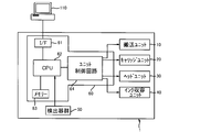
- FIG. 1 is a block diagram illustrating a configuration of a printer 1 including an ink supply system.
- FIG. 2 is a schematic diagram illustrating a cross section of the printer 1 including the ink supply system.
- the printer 1 of Embodiment B is an apparatus that forms an image on a recording surface of a recording medium by ejecting ink toward the recording medium such as paper.
- the printer 1 according to the embodiment B can form images using inks of various colors. For example, cyan, magenta, yellow, and black (hereinafter, “C”, “M”, Forming an image using four color inks of “Y” and “Bk”), or forming a base that imparts excellent concealability to a recording medium using white ink. Is mentioned.
- a clear ink may be applied to these CMYBk and white inks, thereby increasing glossiness.
- the printer 1 includes a transport unit 10, a carriage unit 20, a head unit 30, an ink storage unit 40, a detector group 50, and a controller 60.
- the printer 1 that has received print data from the computer 110, which is an external device, controls each unit (the transport unit 10, the carriage unit 20, the head unit 30, and the ink containing unit 40) by the controller 60.
- the controller 60 controls each unit based on the print data received from the computer 110 and prints an image on a recording medium.
- the situation in the printer 1 is monitored by the detector group 50, and the detector group 50 outputs the detection result to the controller 60.
- the controller 60 controls each unit based on the detection result output from the detector group 50.
- the transport unit 10 is for transporting a recording medium such as paper in a predetermined direction (hereinafter referred to as “transport direction” or “sub-scanning direction”).
- the transport unit 10 includes a paper feed roller 11, a transport motor (not shown), a transport roller 13, a platen 14, and a paper discharge roller 15.
- the paper feed roller 11 is a roller for feeding the recording medium inserted into the paper insertion slot into the printer 1.
- the transport roller 13 is a roller that transports the recording medium fed by the paper feed roller 11 to a printable area, and is driven by a transport motor.
- the platen 14 supports a recording medium being printed.
- the paper discharge roller 15 is a roller for discharging the recording medium to the outside of the printer 1 and is provided on the downstream side in the transport direction with respect to the printable area.
- the carriage unit 20 causes the head 31 to be in a direction intersecting the transport direction (sub-scanning direction) (hereinafter referred to as “moving direction” or “main scanning” while ejecting ink to a recording medium stationary in the recording area. It is a moving mechanism that moves, that is, scans.
- the carriage unit 20 includes a carriage 21, a carriage motor (not shown), and a sub tank (sub ink tank) 22.
- the carriage 21 includes a sub tank 22 and a head 31, and is connected to a carriage motor (not shown) via a timing belt (not shown).
- the carriage 21 is reciprocated along the guide shaft 24 by a carriage motor while being supported by a guide shaft 24 that intersects a conveyance direction described later.
- the guide shaft 24 is supported by the carriage 21 so as to be capable of reciprocating in the axial direction of the guide shaft 24.
- the sub-tank 22 is for suppressing ink pressure fluctuation in the head 31 that may be caused by the reciprocating motion of the carriage 21.
- the sub tank 22 may have, for example, four sub tanks and may store inks of different colors.
- Specific examples of the four subtanks 22 include a subtank that stores black ink, a subtank that stores cyan ink, a subtank that stores magenta ink, and a subtank that stores yellow ink. All of the four sub tanks 22 are mounted on the carriage 21.
- the carriage unit 20 may not include the sub tank 22, and in this case, the ink storage container 41 and the head 31 are connected via the ink supply path 42.
- the sub tank 22 will be described in more detail with reference to FIG.
- the head unit 30 is for ejecting ink to a recording medium.
- the head unit 30 includes a head 31 having a plurality of nozzles. Since the head 31 is provided on the carriage 21, when the carriage 21 moves in the movement direction, the head 31 also moves in the movement direction. An image is formed on the recording surface of the recording medium by ejecting ink while the head 31 moves in the moving direction.
- the four heads 31 may eject ink corresponding to the colors stored in the four sub-tanks 22. That is, specific examples of the four heads 31 include the heads 31 for ejecting black ink, cyan ink, magenta ink, and yellow ink, respectively.
- the ink storage unit 40 stores ink and supplies the stored ink to the head 31 via an ink supply path.
- the ink storage unit 40 includes an ink storage container 41, an ink supply path 42, and a filter 43.
- the ink storage container 41 is placed at a different location from the carriage 21 and is stored in an ink storage container storage (not shown) provided outside the main body of the printer 1 (outside the movement range of the carriage 21). Has been.
- the ink container 41 and the head 31 (carriage 21) are connected by an ink supply path 42. In this case, the ink container 41 does not move.
- the ink container 41 has a structure that allows contact with air and ink. That is, the ink supply system of the above embodiment B allows the ink stored in the ink storage container 41 to contain bubbles. Therefore, according to the ink supply system and the recording apparatus according to the embodiment B including the ink supply system, ink containing a high amount of dissolved nitrogen containing bubbles is stored in the ink storage container 41 regardless of whether or not the deaeration process is performed. can do. Furthermore, the ink container 41 facilitates further supply (replenishment, refilling) of ink.
- the ink storage container 41 is not particularly limited as long as it is a container that can store a conventionally known ink, and examples thereof include an ink tank (with a large capacity) and an open ink cartridge. Therefore, the ink supply system and the recording apparatus described above are extremely effective in a printer system such as an off-carriage type serial printer.
- the four ink storage containers 41 may store ink corresponding to the colors stored in the four sub tanks 22. That is, specific examples of the four ink storage containers 41 include the ink storage containers 41 that respectively store black ink, cyan ink, magenta ink, and yellow ink. Each ink container 41 can confirm the ink level from the outside from a predetermined portion.
- the ink container 41 is a component of the printer 1. However, since the ink container 41 is provided outside the main body of the printer 1, the ink container 41 contains less ink than the sub tank 22 because it has less spatial restrictions. Can do.
- the ink supply path 42 is an ink flow path for connecting the ink container 41 and the head 31 and supplying ink in the ink container 41 to the head 31.
- the ink supply path 42 can connect the ink storage container 41 that can store the ink of each color and the sub tank 22 for storing the ink of the corresponding color.
- the ink supply path 42 can be formed of a flexible member such as synthetic rubber, and can be referred to as a hose or a tube.
- the filter 43 is provided in the flow path of the ink supply path 42.
- the filter 43 can prevent the bubbles from flowing into the head by capturing the bubbles. Thereby, both the ink filling in the head 31 and the ink ejection from the head 31 are excellent, and both the initial filling property and the continuous printing stability are excellent.
- the installation location of the filter 43 is not particularly limited.
- the filter 43 may be provided near the outlet of the ink container 41 (the liquid outlet 306).
- bubbles tend to be generated when ink is filled or when ink is consumed. By suppressing the bubbles from flowing into the flow path, the initial filling property and the continuous printing stability can be further improved.
- a plurality of filters 43 may be provided, but in order to maintain a good ink flow, the number of filters provided in one flow path is preferably about 1 to 3, more preferably 1.
- the average hole diameter of the filter 43 is preferably equal to or smaller than the nozzle diameter of the nozzles of the head 31 in order to prevent nozzle omission due to air bubbles being ejected from the nozzles of the head 31.
- the nozzle diameter is usually about 10 to 30 ⁇ m.
- the “average pore diameter of the filter” in the present specification means that 50% of the beads having the same diameter as the average pore diameter can be removed.
- nozzle diameter” in the present specification means the diameter of the thinnest part of the nozzle.
- the material of the filter 43 is not limited to the following, and examples thereof include a resin (nonwoven fabric, maps) such as stainless steel (mesh) and polypropylene.
- the material of the filter 43 is preferably resin because it is easy to trap impurities such as foreign matter that may be generated in the flow path due to the resin or rubber member forming the tank or the tube. By capturing the impurities and the bubbles with the filter 43, it is possible to prevent the impurities from adhering to the bubbles or being carried alone to the nozzles of the head 31 to cause nozzle omission. That is, by making the material of the filter 43 preferable as described above, the initial filling property and the continuous printing stability can be further improved.
- the detector group 50 includes a linear encoder (not shown), a rotary encoder (not shown), a paper detection sensor 53, an optical sensor 54, and the like.
- the linear encoder detects the position of the carriage 21 in the moving direction.
- the rotary encoder detects the amount of rotation of the transport roller 13.
- the paper detection sensor 53 detects the position of the leading end of a recording medium such as paper being fed.
- the optical sensor 54 detects the presence or absence of a recording medium using a light emitting unit and a light receiving unit attached to the carriage 21.
- the optical sensor 54 can detect the position of the end of the recording medium while being moved by the carriage 21 to detect the width of the recording medium.
- the optical sensor 54 has a leading end (an end on the downstream side in the transport direction, also referred to as “upper end”) and a rear end (an end on the upstream side in the transport direction, depending on the situation). It can also be detected as “lower end”.
- the controller 60 is a control unit (control unit) for controlling the printer 1.
- the controller 60 includes an interface unit 61, a CPU 62, a memory 63, and a unit control circuit 64.
- the interface unit 61 transmits and receives data between the computer 110 that is an external device and the printer 1.
- the CPU 62 is an arithmetic processing unit for controlling the entire printer 1.
- the memory 63 is for securing an area for storing a program of the CPU 62, a work area, and the like, and includes storage elements such as a RAM and an EEPROM.
- the CPU 62 controls each unit via the unit control circuit 64 in accordance with a program stored in the memory 63.
- the controller 60 controls the dot forming operation for ejecting ink from the head 31 moving in the moving direction and the transporting operation for transporting the recording medium in the transport direction alternately as described later.
- the controller 60 controls the dot forming operation for ejecting ink from the head 31 moving in the moving direction and the transporting operation for transporting the recording medium in the transport direction alternately as described later.
- the ink jet recording apparatus according to the present embodiment B provided with the above ink supply system forms an image in a region facing the head 31 of the recording medium.
- the operation of the recording apparatus of Embodiment B includes a recording operation for forming an image by attaching ink to a recording medium, and a conveying operation for conveying the recording medium.
- the recording apparatus of Embodiment B performs recording by alternately performing a recording operation and a transport operation. During recording, the recording medium is not conveyed but is held by the platen 14 located in the recording area.
- the recording operation is not limited to the following, but for example, ink supply operation for supplying ink from the ink storage container 41 to the head 31 and ink storage for the purpose of stably supplying ink from the ink tank 44 to the head 31.
- Examples thereof include an air introduction operation for introducing the atmosphere (air) into the container 41 and an ejection operation for ejecting ink from the head 31 toward the recording medium.
- an air introduction operation for introducing the atmosphere (air) into the container 41
- an ejection operation for ejecting ink from the head 31 toward the recording medium.
- the ink supply operation described above includes an operation of further supplying (replenishing) ink that has been supplied and reduced to the ink container 41.
- the operation of the recording apparatus of the embodiment B can be rephrased as an ink jet recording method using an ink supply system, and each operation included in the operation of the above-described recording apparatus is rephrased as a “process”. Can do.
- the ink-absorbing recording medium is not particularly limited.
- plain paper such as electrophotographic paper having high water-based ink permeability
- inkjet paper an ink absorbing layer composed of silica particles or alumina particles
- Art paper used for general offset printing with relatively low penetrability of water-based ink from an ink-dedicated paper having an ink absorbing layer composed of a hydrophilic polymer such as polyvinyl alcohol (PVA) or polyvinyl pyrrolidone (PVP) , Coated paper, cast paper, and the like.
- PVA polyvinyl alcohol
- PVP polyvinyl pyrrolidone
- the recording operation in Embodiment B includes an ink supply operation.
- the ink supply operation supplies ink from the ink container 41 to the head 31, and the ink supply system of the above-described embodiment B can be used.
- the ink supply operation will be described in detail later.
- the recording operation in the present embodiment B may further include an air introduction operation.
- the air introduction operation assists the ink supply operation, and the ink supply system of Embodiment B can be used.
- the air introduction operation is performed. Done.
- air (air) is introduced into the ink container 41 for the purpose of stably supplying ink from the ink tank 44 to the head 31.
- the air introduction operation will be described in detail later.
- the recording operation in the present embodiment B includes an ejection operation.
- the ejection operation is an inkjet recording method in which an ink droplet is ejected onto a recording medium to form an image.
- a discharge method a conventionally known method can be used.
- Various discharge conditions such as the discharge temperature and time and the viscosity of the discharged ink are not particularly limited.
- FIG. 3 is a schematic diagram for explaining the principle of ink supply from the ink tank 44, which is an example of the ink container 41, to the head 31.
- the ink supply method shown in FIG. 3 is based on the principle of the Marriott bottle in short, and the head 31 and the ink tank 44 are connected via the sub tank 22 and the ink supply path 42 provided in the carriage 21.
- the ink is sucked and supplied from the ink tank 44 to the head 31 by being connected and generating a negative pressure inside the sub tank 22.
- FIG. 3 schematically shows mainly the interior of the ink tank 44, the ink supply path 42, and the sub tank 22.
- the printer 1 is installed on a predetermined horizontal plane sf.
- the liquid outlet 306 of the ink tank 44 and the liquid receiver 202 of the sub tank 22 are connected via the ink supply path 42.
- the sub tank 22 is formed of a synthetic resin such as polystyrene or polyethylene.
- the sub tank 22 includes an ink storage chamber 204, an ink flow path 208, and a filter 206.
- An ink supply needle 21 a of the carriage 21 is inserted into the ink flow path 208.
- the filter 206 prevents inflow of impurities into the head 31 by capturing impurities when impurities such as foreign matter are mixed in the ink flowing through the ink flow path 206.
- the ink in the ink storage chamber 204 is supplied to the head 31 through the ink flow path 208 and the ink supply needle 21 a by suction from the head 31.
- the ink supplied to the head 31 is ejected and attached to the recording medium through the nozzles to form an image (the above-described ejection operation).
- the ink supply path 42 connects the ink container 41 and the head 31.
- the ink supply path 42 also exists in the sub tank 22. Therefore, in the above case, both the filter 43 and the filter 206 correspond to filters provided in the ink supply path 42.
- FIG. 3 is a preferred embodiment in which a filter 206 is provided in the flow path in the sub tank 22.
- the aspect provided with both the filter 43 and the filter 206 like FIG. 3 may be sufficient, and the aspect provided only with the filter 206 may be sufficient.
- the bubble 43 produced just before the head 31 (upstream side) can be effectively collected by providing the filter 43 in front of the head 31 (upstream side).
- a mode in which a filter is provided inside the ink supply needle 21a to which the sub tank 22 is attached can be mentioned. According to this mode, it is possible to effectively collect bubbles generated when the cartridge is attached or detached.
- a plurality of filters can also be provided in an embodiment in which a filter is provided inside the ink supply needle.
- the ink tank 44 supplies ink to the head 31 of the printer 1 using the principle of the Marriott bottle.
- the outer surface of the ink tank 44 includes a first wall 370C1, a second wall (upper surface wall) 370C2, and a bottom wall 370C3.
- the ink tank 44 has an air introduction channel and an ink channel inside thereof.
- the air introduction channel is a channel for introducing air from the atmosphere opening port 317 to the liquid storage chamber 340 through the atmosphere introduction port 318 via an atmosphere channel (not shown).
- This ink flow path is a flow path for performing ink injection (including “replenishment”; the same applies hereinafter) from the liquid flow path 304 to the liquid outlet 306 through the liquid storage chamber 340.
- the air introduction flow path is a flow path used in the air introduction operation described above.
- the air introduction flow path includes an atmosphere opening port 317 that opens toward the outside (atmosphere), an air storage chamber 330 that has the air introduction port 318 as one end and the air chamber side opening 351 as the other end, and an air chamber side opening 351. And a liquid chamber communication path 350 having the air inlet 352 as the other end.
- the atmosphere opening port 317 communicates with the atmosphere
- the air storage chamber 330 opens at the atmosphere introduction port 318 at one end
- the atmosphere opening port 317 and the atmosphere introduction port 318 communicate with each other via a channel (not shown). That is, the air accommodating chamber 330 communicates with the outside (atmosphere).
- the air storage chamber 330 communicates with the liquid storage chamber 340.
- the liquid chamber communication path 350 preferably has a flow passage cross-sectional area small enough to form a meniscus (liquid level cross-linking).
- the air introduction port 352 that is one end opens at the liquid storage chamber 340, and the atmosphere opening port 317 that is the other end opens toward the outside. That is, when the ink tank 44 to be described later is used, a liquid surface that is in direct contact with the atmosphere is formed in the liquid chamber communication path 350 (specifically, in the vicinity of the air inlet 352), and the liquid storage chamber is formed from the air inlet 352. Air (bubbles) is introduced into the liquid storage chamber 340 by introducing air (bubbles) into the ink 340. Accordingly, as described later, ink can be stably supplied from the ink tank 44 to the head 31. In other words, the air introduction operation described so far is performed for the purpose of stabilizing the ink supply operation described later.
- the ink flow path is used in the ink supply operation described above. These ink supply operations are performed as the amount of ink stored in the ink tank 44 is reduced due to the ejection operation from the head 31, and are stably performed by the air introduction operation.
- the ink tank 44 has a use state and an injection state.
- the “use state” is a state of the ink tank 44 installed on the horizontal plane when supplying ink to the head 31 of the printer 1.
- the liquid injection path 304 is open in the horizontal direction (however, the opening is closed by the plug member 302).
- FIG. 3 shows the ink tank 44 in use.
- the liquid storage chamber 340 and the air storage chamber 330 are arranged in the horizontal direction.
- the air inlet 352 is positioned below the liquid level of the liquid stored in the liquid storage chamber 340.
- the “injection state” is a state of the ink tank 44 installed on a horizontal plane when ink is injected into the ink tank 44.
- the liquid injection path 304 is open upward.
- the liquid storage chamber 340 and the air storage chamber 330 are arranged in the vertical direction.
- the air introduction port 352 has a liquid amount when the liquid level of the liquid stored in the liquid storage chamber 340 in the use state is on the straight line LM1 (“first state display line LM1”).
- first state display line LM1 When stored in the storage chamber 340, it is located above the liquid level of the liquid stored in the liquid storage chamber 340.
- the user may stop the ink replenishment when the ink liquid level reaches the vicinity of the straight line LM2 ("second state display line LM2") that is horizontal in the injection state.
- the liquid injection path 304 is sealed with the plug member 302. Further, the ink in the liquid storage chamber 340 is sucked from the head 31 so that the liquid storage chamber 340 is maintained at a negative pressure.
- the air introduction port 352 is located below the first state display line LM1.
- the air introduction port 352 is formed in the bottom wall 370 ⁇ / b> C ⁇ b> 3 located on the lower side of the container main body 45 that partitions and forms the liquid storage chamber 340 with the liquid storage chamber 340 in the use state.
- the liquid level (atmospheric contact liquid level) LA in contact with the atmosphere is long (the ink level is in the first state). It is maintained at a constant height over a period of time until it reaches the display line LM1.
- the air inlet 352 is disposed at a position lower than the head 31 in the use state.
- the water head difference d1 occurs.
- the water head difference d1 in a state where the air contact liquid level LA that is a meniscus is formed in the vicinity of the air inlet 352 of the liquid chamber communication path 350 is also referred to as “steady-state water head difference d1” below.
- the ink storage chamber 204 When the ink in the ink storage chamber 204 is sucked by the head 31, the ink storage chamber 204 becomes equal to or higher than a predetermined negative pressure.
- the ink storage chamber 204 reaches a predetermined negative pressure or higher, the ink in the liquid storage chamber 340 is supplied to the ink storage chamber 204 via the ink supply path 42. That is, the ink storage chamber 204 is automatically further supplied (supplemented) with the amount of ink that has flowed out of the head 31 from the liquid storage chamber 340.
- the water head difference d1 generated by the vertical height difference between the air storage chamber 330 in the ink tank 44 that is, the atmospheric contact liquid surface (ink liquid surface) LA in contact with the atmosphere, and the nozzle surface of the head 31.
- the suction force (negative pressure) from the head 31 side being increased to some extent, the ink is supplied from the liquid storage chamber 340 to the ink storage chamber 204.
- the air in the air storage chamber 330 is introduced as bubbles G into the liquid storage chamber 340 via the liquid chamber communication path 350. That is, in the liquid storage chamber 340 of the ink tank 44, the atmosphere introduced through the air introduction channel contacts the ink injected through the ink channel. As a result, the ink level LF in the liquid storage chamber 340 is lowered. On the other hand, since the height of the atmospheric contact liquid level LA in contact with the atmosphere is maintained constant, the water head difference d1 is maintained constant. That is, the predetermined suction force of the head 31 can stably supply ink from the ink tank 44 to the head 31 in terms of the amount of ink.
- the ink tank 44 can supply ink stably, a part of the bubbles G flows out to the liquid outlet 306 together with the ink and is carried to the head 31 to cause a problem such as missing dots. Occurs. More specifically, as shown in the figure surrounded by the upper left square in FIG. 3, when the bubble G is generated in the ink from the air inlet 352, the bubble G is split, and the bubble Ga having a normally assumed size and In addition, there may be a case where micro bubbles Gb that are considerably smaller than the size of the air inlet 352 are generated. In the ink tank 44, the microbubbles Gb have a diameter of about several tens of ⁇ m, for example.
- the buoyancy of the microbubbles Gb is small (for example, 0.1 mm / s) and is particularly susceptible to the ink flow in the liquid storage chamber 340.
- the microbubbles Gb flow along the ink flow and flow into the head 31 side of the printer 1 through the liquid outlet 306, causing problems such as missing dots. It becomes easy to do.
- the filter 43 is provided in the flow path of the ink supply path 42 and the ink composition is set to a predetermined value. It has been found that Gb can be captured and the inflow of the microbubbles Gb into the head 31 can be prevented. Thereby, the ink supply system of Embodiment B and the recording apparatus of Embodiment B equipped with the ink supply system can improve ejection and have excellent continuous printing stability.
- an off-carriage type serial printer has a dot structure caused by an ink supply container such as an ink tank 44 having a structure in which the air introduced from the outside contacts the ink in order to stabilize the ink supply. Problems such as omission are likely to occur. Therefore, when the ink supply system and the recording apparatus equipped with the ink supply system are applied to an off-carriage type serial printer, the ink described later actively removes bubbles attached to members such as the ink container 41 and the ink supply path 42. And may contain undesirable bubbles such as microbubbles Gb.
- the ink supply system and the recording apparatus including the ink supply system have an extremely excellent effect when applied to an off-carriage type serial printer.
- the ink supply system of the above embodiment B and the recording apparatus of the present embodiment B including the ink supply system are not limited to the specific examples described so far, and can be modified in various forms without departing from the gist thereof. It is possible to implement. For example, the following modifications are mentioned.
- the ink is supplied from the ink tank 44 to the head 31 by pressurizing with a pump. It may be supplied.
- the ink tank 44 and the head 31 may be connected via the ink supply path 42 without providing the sub tank 22.
- the recording apparatus of Embodiment B may be an on-carriage type serial printer in which an ink cartridge (ink tank, not shown) is mounted on the carriage 21 together with the head 31.
- the carriage 21 detachably holds an ink cartridge (not shown) that stores ink.
- the ink cartridge (not shown) has an open system structure that does not block the inflow of the atmosphere, the ink supply system and the recording apparatus including the ink supply system have a significant effect.
- an ink cartridge (not shown) in the on-carriage type serial printer may have the same configuration as that of the sub tank 22 described above.
- a large-capacity ink tank (not shown) may be added outside the on-carriage type serial printer.
- the large-capacity ink tank can be connected to the ink cartridge via an ink supply path (not shown).
- the large-capacity ink tank and the ink supply path may have the same configuration as the ink tank 44 and the ink supply path 42 described above.
- the recording apparatus of the embodiment B may be a line printer.
- an ink supply system that is excellent in initial filling property and continuous printing stability even in the case of ink containing bubbles (the amount of dissolved nitrogen is, for example, 5 ppm or more) and An ink jet recording apparatus provided with this can be provided.
- the ink is used in the ink supply system of Embodiment B and the ink jet recording apparatus including the ink supply system.
- the ink contains an alkylene oxide adduct (A) of acetylene glycol having a main chain having 12 or more carbon atoms and a polyoxyalkylene alkyl ether (C).
- the AO adduct of acetylene glycol having 12 or more carbon atoms in the main chain contained in the ink imparts excellent wettability to the ink, and air bubbles adhering to the surfaces of members such as an ink container and an ink supply path are taken into the ink.
- the trapped air bubbles are captured by the filter, and the air bubbles are removed from the ink.
- Embodiment B contains an alkylene oxide adduct (A) of acetylene glycol having a main chain having 12 or more carbon atoms in Embodiment A described above. Therefore, specific examples and preferable contents are also the same as those in the above-described embodiment A.
- Embodiment B includes the polyoxyalkylene alkyl ether (C) in Embodiment A described above. Therefore, specific examples and preferable contents are also the same as those in the above-described embodiment A.
- the ink in Embodiment B may contain a surfactant other than those described above (hereinafter referred to as “other surfactant”).
- the ink of Embodiment B preferably contains acetylene glycol (B) having 10 or more carbon atoms in the main chain in Embodiment A described above.
- acetylene glycol surfactants acetylene glycol having 10 or more carbon atoms in the main chain can effectively defoam bubbles generated in the ink. Thereby, initial filling property and continuous printing stability are further improved. Specific examples and preferred contents are the same as those in the above-described embodiment A.
- the ink in Embodiment B preferably further contains a colorant. Specific examples and preferable contents are the same as those in the above-described embodiment A.
- the ink in Embodiment B may contain water. Specific examples and preferable contents are the same as those in the above-described embodiment A.
- the ink in Embodiment B preferably further contains an organic solvent. Specific examples and preferable contents are the same as those in the above-described embodiment A.
- the ink of Embodiment B may further contain a pH adjuster such as triethanolamine and tripropanolamine, an antiseptic / fungicide, a rust inhibitor, a chelating agent, and the like.
- a pH adjuster such as triethanolamine and tripropanolamine, an antiseptic / fungicide, a rust inhibitor, a chelating agent, and the like.
- Embodiment B [Ink production method]
- the ink of Embodiment B can be produced in the same manner as in Embodiment A described above.
- the ink supply system excellent in initial filling property and continuous printing stability and the ink jet recording apparatus including the ink supply system can be suitably used, and further, dissolution stability and storage stability can be used.
- the ink can be provided.
- Example A [Materials used]
- the main materials used in the following examples and comparative examples are as follows. ⁇ dye ⁇ ⁇ C.
- Surfactant (1. Alkylene oxide adduct of acetylene glycol having 12 or more carbon atoms in the main chain)
- Surfactant 1 (12 main chain carbon atoms, with addition of ethylene oxide, 2,5,8,11-tetramethyl-6-dodecine-5,8-diol ethoxylate) (2.
- Acetylene glycol having 10 or more carbon atoms in the main chain Surfactant 2 (main chain 12 carbon atoms, no addition of ethylene oxide, 2,5,8,11-tetramethyl-6-dodecyne-5,8-diol)
- Surfactant 3 main chain carbon number 10, no addition of ethylene oxide, 2,4,7,9-tetramethyl-5-decyne-4,7-diol) (3.
- Surfactant 4 (10 main chain carbon atoms, 10 added moles of ethylene oxide, ethoxylate of 2,4,7,9-tetramethyl-5-decyne-4,7-diol)
- Surfactant 5 (10 main chain carbon atoms, ethylene oxide addition moles 4, 2, 4, 7, 9-tetramethyl-5-decyne-4,7-diol ethoxylate)
- Surfactant 6 (main chain carbon number 8, no addition of ethylene oxide, 3,6-dimethyl-4-octyne-3,6-diol)
- Polyoxyalkylene alkyl ether Polyoxyalkylene alkyl ether 1 (HLB value 15.0, hereinafter referred to as “POAAE1”)
- the chemical formula of POAAE1 is shown below.
- RO C 2 H 4 O
- w C 3 H 6 O
- x C 2 H 4 O
- y C 3 H 6 O
- z H
- R alkyl having 12 carbon atoms
- POAAE2 Polyoxyalkylene alkyl ether 2 (HLB value 12.0, hereinafter referred to as “POAAE2”)
- HLB value 12.0 hereinafter referred to as “POAAE2”
- RO C 2 H 4 O
- w C 3 H 6 O
- x 5.
- POAAE3 Polyoxyalkylene alkyl ether 3 (HLB value 10.9, hereinafter referred to as “POAAE3”)
- HLB value 10.9 hereinafter referred to as “POAAE3”
- RO C 2 H 4 O
- w C 3 H 6 O
- x 4.
- Examples 1A to 9A, Comparative Examples 1A to 8A, Reference Examples 1A to 2A Each ink composition was prepared by mixing and stirring each component according to the composition shown in Table 1 and Table 2 below. Further, each ink composition was filtered with a membrane filter having a pore size of 1 ⁇ m to remove the impurities. In Tables 1 and 2 below, the unit of numerical values is mass%, and the total is 100.00 mass%.
- ⁇ Ejected from all nozzles only in the initial filling sequence.
- delta The frequency
- X The number of cleanings required until ink could be ejected from all nozzles was 2 or more.
- the ink composition (each example) containing ether (C) is excellent in initial filling property and continuous printing stability, and further has dissolution stability and storage, as compared with the ink composition (each comparative example) that does not. It was found to be excellent in stability.
- the ink composition (each example) was a degassed ink composition (each reference example, the ink composition itself was equivalent to a comparative example). It was found that the initial filling property, the continuous printing stability, the dissolution stability, and the storage stability are all equal to or better than the above.
- Example B [Materials used]
- the main materials used in the following examples and comparative examples are as follows. [Pigment] ⁇ C.
- Surfactant 1 (12 main chain carbon atoms, with addition of ethylene oxide, ethoxylate of 2,5,8,11-tetramethyl-6-dodecyne-5,8-diol) (2.
- Acetylene glycol having 10 or more carbon atoms in the main chain Surfactant 2 (main chain 12 carbon atoms, no addition of ethylene oxide, 2,5,8,11-tetramethyl-6-dodecyne-5,8-diol) Surfactant 3 (main chain carbon number 10, no addition of ethylene oxide, 2,4,7,9-tetramethyl-5-decyne-4,7-diol) (3. Other acetylene glycol compounds) Surfactant 4 (10 main chain carbon atoms, 10 ethylene oxide addition moles.
- Polyoxyalkylene alkyl ether 2 (HLB value 12.0, hereinafter referred to as “POAAE2”) The chemical formula of POAAE2 is shown below.
- Polyoxyalkylene alkyl ether 3 (HLB value 10.9, hereinafter referred to as “POAAE3”)
- the chemical formula of POAAE3 is shown below.
- R is alkyl having 12 carbons
- ⁇ Organic solvent Triethylene glycol triethylene glycol monobutyl ether (hereinafter referred to as “TEGmBE”) ⁇ Propylene glycol ⁇ Dipropylene glycol ⁇ Glycerin ⁇ Triethanolamine
- Examples 1B to 5B, Comparative Examples 1B to 5B, Reference Examples 1B to 2B Each ink was prepared by mixing and stirring each component according to the composition shown in Table 4 and Table 5 below. In addition, each ink was filtered through a membrane filter having a pore diameter of 1 ⁇ m to remove a refreshing matter. In Tables 4 and 5 below, the unit of numerical values is mass%, and the total is 100.00 mass%.
- the initial filling property was evaluated according to the following evaluation criteria. The evaluation results are shown in Table 6 below.
- ⁇ Ejected from all nozzles only in the initial filling sequence.
- X The number of cleanings required until ink could be ejected from all nozzles was 2 or more.
- an ink container that can be contacted with air and ink, a head for ejecting ink, an ink container that connects the ink container and the head, and an ink supply path through which ink flows from the ink container to the head
- a filter (D) provided in the ink supply path
- the ink comprising an alkylene oxide adduct (A) of acetylene glycol having a main chain of 12 or more carbon atoms, and a polyoxyalkylene alkyl ether (C)
- an ink jet recording apparatus (each example) provided with the system, as compared with an ink supply system and an ink jet recording apparatus (each comparative example) that do not, the initial filling property and the continuous printing stability It was found that the ink was excellent in solubility, and further, was excellent in dissolution stability and storage stability of the ink. Further, it was found that the continuous printing stability was particularly excellent when the acetylene glycol (B) having 10 or more carbon atoms in
- the ink in Reference Example 1B was slightly degassed so that the amount of dissolved nitrogen was 5.5 ppm.
- the ink in Reference Example 2B was sufficiently deaerated to have a dissolved nitrogen content of 1.4 ppm.
- the amount of dissolved nitrogen in the ink that is hardly degassed that is, the ink that is hardly degassed is, for example, 5 ppm or more, and the ink that is not degassed at all, that is, the ink that is not degassed at all.
- the amount of nitrogen is, for example, 7 ppm or more (the examples and the comparative examples are not deaerated at all).
- memory 64 ... unit control circuit 110 ... computer 202 ... liquid receiving unit 204 ... ink reservoir chamber , 206 ... Filter, 208 ... Ink flow path, 302 ... Plug member, 304 ... Liquid Injection path, 306 ... liquid outlet, 317 ... atmosphere opening port, 318 ... atmosphere introduction port, 330 ... air storage chamber, 340 ... liquid storage chamber, 350 ... liquid chamber communication path, 351 ... air chamber side opening, 352 ... air Inlet, 370C1 ... first wall, 370C2 ... second wall (top wall), 370C3 ... bottom wall, d1 ... (steady state) water head difference, G ... bubble, Ga ... bubble, Gb ... microbubble, LA ... Air contact liquid level (ink liquid level), LF... Ink liquid level, LM1... First status display line, LM2... Second status display line, sf.
Landscapes
- Chemical & Material Sciences (AREA)
- Life Sciences & Earth Sciences (AREA)
- Engineering & Computer Science (AREA)
- Materials Engineering (AREA)
- Wood Science & Technology (AREA)
- Organic Chemistry (AREA)
- Inks, Pencil-Leads, Or Crayons (AREA)
- Ink Jet Recording Methods And Recording Media Thereof (AREA)
- Ink Jet (AREA)
Abstract
Description
[1]
主鎖の炭素数が12以上であるアセチレングリコールのアルキレンオキサイド付加物(A)と、
主鎖の炭素数が10以上であるアセチレングリコール(B)と、
ポリオキシアルキレンアルキルエーテル(C)と、を含む、インクジェット記録用インク組成物。
[2]
前記ポリオキシアルキレンアルキルエーテル(C)のHLB値が12~16である、[1]に記載のインクジェット記録用インク組成物。
[3]
前記アルキレンオキサイド付加物がエチレンオキサイド付加物である、[1]に記載のインクジェット記録用インク組成物。
[4]
ポリオキシアルキレンアルキルエーテル(C)の含有量と、主鎖の炭素数が12以上であるアセチレングリコールのアルキレンオキサイド付加物(A)及び主鎖の炭素数が10以上であるアセチレングリコール(B)の総含有量と、の質量比は、0.10:1.0~0.50:1.0の範囲である、[1]に記載のインクジェット記録用インク組成物。
[5]
前記主鎖の炭素数が12以上であるアセチレングリコールのアルキレンオキサイド付加物(A)のHLB値が、8~15である、[1]に記載のインクジェット記録用インク組成物。
[6]
前記主鎖の炭素数が10以上であるアセチレングリコール(B)のHLB値が、4以下である、[1]に記載のインクジェット記録用インク組成物。
[7]
着色剤をさらに含む、[1]に記載のインクジェット記録用インク組成物。
[8]
有機溶剤をさらに含む、[1]に記載のインクジェット記録用インク組成物。
[9]
大気及びインクが接触可能な、[1]に記載のインクを収容するインク収容容器と、
前記インクを吐出するプリントヘッドと、
前記インク収容容器及び前記プリントヘッドを接続し、前記インク収容容器から前記プリントヘッドへ前記インクが流れるインク供給路と、
前記インク供給路に設けられたフィルター(D)と、を備える、インク供給システム。
[10]
前記フィルターの平均孔径は、前記プリントヘッドのノズルのノズル径以下である、[9]に記載のインク供給システム。
[11]
前記フィルター(D)が、前記インク供給路に複数設けられる、[9]に記載のインク供給システム。
[12]
前記フィルター(D)の材質は樹脂である、[9]に記載のインク供給システム。
[13]
[9]に記載のインク供給システムを備え、
前記インク収容容器から前記プリントヘッドへ供給される前記インクを、該プリントヘッドから被記録媒体に向けて吐出し記録を行う、インクジェット記録装置。
[インクジェット記録用インク組成物]
本発明の一実施形態は、インクジェット記録用インク組成物(以下、単に「インク組成物」ともいう。)に係る。当該インク組成物は、主鎖の炭素数が12以上であるアセチレングリコールのアルキレンオキサイド付加物(A)と、主鎖の炭素数が10以上であるアセチレングリコール(B)と、ポリオキシアルキレンアルキルエーテル(C)と、を含むものである。
以下、本実施形態Aのインク組成物に含まれるか、又は含まれ得る添加剤(成分)を説明する。
本実施形態Aのインク組成物は、主鎖の炭素数が12以上であるアセチレングリコールのアルキレンオキサイド付加物(A)を含む(以下、アルキレンオキサイド付加物を「AO付加物」ともいう。)。当該主鎖の炭素数12以上のアセチレングリコールのAO付加物は、後述する主鎖の炭素数が10以上であるアセチレングリコールとともに、アセチレングリコール系界面活性剤に含まれるものである。なお、本明細書における「主鎖」とは、IUPAC命名法に基づく主鎖を意味する。
なお、上記の事項は、本実施形態Aのインク組成物が主鎖の炭素数12以上のアセチレングリコールのAO付加物の代わりに主鎖の炭素数12以上のアセチレングリコールを含む場合について説明したものにすぎず、後述する主鎖の炭素数10以上のアセチレングリコールのうち炭素数が12以上のものとは何ら関係のない事項である。つまり、本実施形態Aのインク組成物が主鎖の炭素数12以上のアセチレングリコールのAO付加物と主鎖の炭素数10以上のアセチレングリコールのうち炭素数が12以上のものとを含む場合、これらの水系インク中での溶解性は優れたものとなる。

本実施形態Aのインク組成物は、主鎖の炭素数が10以上であるアセチレングリコールを含む。アセチレングリコール系界面活性剤のうち、主鎖の炭素数10以上のアセチレングリコールは、インク中に発生した気泡を効果的に消泡させることができる。これにより、初期充填性及び連続印刷安定性が優れたものとなる。

本実施形態Aのインク組成物は、ポリオキシアルキレンアルキルエーテルを含む。上記した主鎖の炭素数12以上のアセチレングリコールのAO付加物と主鎖の炭素数10以上のアセチレングリコールとは、いずれも水又は水系有機溶媒への溶解性が良好でない。そこで、インク組成物がポリオキシアルキレンアルキルエーテルをさらに含むことにより、当該ポリオキシアルキレンアルキルエーテルが上記のアセチレングリコールをインク中に溶解、又は分散させる可溶化剤として作用するものである。つまり、ポリオキシアルキレンアルキルエーテルは上記のアセチレングリコール系化合物の可溶化剤である。さらに、上記のアセチレングリコールはいずれも動的表面張力が低く、ポリオキシアルキレンアルキルエーテルはこの低い動的表面張力に影響を及ぼさない可溶化剤ということができる。
C12H25O(C2H4O)6(C3H6O)2(C2H4O)6(C3H6O)8H、
C13H27O(C2H4O)6(C3H6O)2(C2H4O)6(C3H6O)8H、
C12H25O(C2H4O)w(C3H6O)x(C2H4O)y(C3H6O)zH
(但し、w+y=15且つx+z=4)、
C13H27O(C2H4O)w(C3H6O)x(C2H4O)y(C3H6O)zH
(但し、w+y=15且つx+z=4)、
C12H25O(C2H4O)8(C3H6O)2(C2H4O)6H、
C13H27O(C2H4O)8(C3H6O)2(C2H4O)6H、
C12H25O(C2H4O)12(C3H6O)2(C2H4O)12H、
C13H27O(C2H4O)12(C3H6O)2(C2H4O)12H、
CH3(CH2)9(CH3)CHO(C2H4O)7(C3H6O)4.5H、
CH3(CH2)11(CH3)CHO(C2H4O)7(C3H6O)4.5H、
CH3(CH2)9(CH3)CHO(C2H4O)5(C3H6O)3.5H、
CH3(CH2)11(CH3)CHO(C2H4O)5(C3H6O)3.5H、
C14H29O(C2H4O)14(C3H6O)2H、
C11H23O(C2H4O)8H、
C10H21O(C2H4O)11H、及び
C12H25O(C2H4O)15H、が挙げられる。
本実施形態Aにおけるインクは、上記以外の界面活性剤(以下、「その他の界面活性剤」と言う。)を含んでもよい。
本実施形態Aにおけるインクは、着色剤をさらに含むことが好ましい。当該着色剤としては、特に限定されず、染料及び顔料のいずれも用いることができる。着色剤が呈する色としては、例えば、イエロー、マゼンタ、シアン、ブラック、ホワイト、グリーン、オレンジ、レッド、ブルー、ライトイエロー、ライトマゼンタ、ライトイエロー、ライトブラック、ライトグリーン、ライトオレンジ、ライトレッド、及びライトブルーが挙げられる。
本実施形態Aにおけるインクは、水を含有してもよい。特に、当該インクが水性インクである場合、水はインク組成物の主溶媒であり、インクジェット記録において被記録媒体が加熱される際、蒸発飛散する成分となる。
なお、水又は水系有機溶媒を主溶媒として含有するインクは、水性インクに相当する。ここでいう「主溶媒」とは、インク組成物中のあらゆる溶媒のうち最も含有量の多い溶媒成分をいう。また、本明細書における「水系有機溶媒」とは、水と水溶性有機溶剤との混合溶媒を意味する。
本実施形態Aにおけるインクは、有機溶剤をさらに含むことが好ましい。当該有機溶剤の中でも、揮発性の水溶性有機溶剤がより好ましい。当該揮発性の水溶性有機溶剤としては、以下に限定されないが、例えば、グリセリン、エチレングリコール、ジエチレングリコール、トリエチレングリコール、プロピレングリコール、ジプロピレングリコール、1,3-プロパンジオール、1,2-ブタンジオール、1,2-ペンタンジオール、1,2-ヘキサンジオール、1,4-ブタンジオール、1,5-ペンタンジオール、1,6-ヘキサンジオール、ジエチレングリコールモノ-n-プロピルエーテル、エチレングリコールモノ-iso-プロピルエーテル、ジエチレングリコールモノ-iso-プロピルエーテル、エチレングリコールモノ-n-ブチルエーテル、エチレングリコールモノ-t-ブチルエーテル、ジエチレングリコールモノ-n-ブチルエーテル、トリエチレングリコールモノブチルエーテル、ジエチレングリコールモノ-t-ブチルエーテル、プロピレングリコールモノメチルエーテル、プロピレングリコールモノエチルエーテル、プロピレングリコールモノ-t-ブチルエーテル、プロピレングリコールモノ-n-プロピルエーテル、プロピレングリコールモノ-iso-プロピルエーテル、プロピレングリコールモノ-n-ブチルエーテル、ジプロピレングリコールモノ-n-ブチルエーテル、ジプロピレングリコールモノ-n-プロピルエーテル、ジプロピレングリコールモノ-iso-プロピルエーテル、ジエチレングリコールジメチルエーテル、ジエチレングリコールジエチルエーテル、ジエチレングリコールジブチルエーテル、ジエチレングリコールエチルメチルエーテル、ジエチレングリコールブチルメチルエーテル、トリエチレングリコールジメチルエーテル、テトラエチレングリコールジメチルエーテル、ジプロピレングリコールジメチルエーテル、ジプロピレングリコールジエチルエーテル、トリプロピレングリコールジメチルエーテル、メタノール、エタノール、n-プロピルアルコール、iso-プロピルアルコール、n-ブタノール、2-ブタノール、tert-ブタノール、iso-ブタノール、n-ペンタノール、2-ペンタノール、3-ペンタノール、及びtert-ペンタノール等のアルコール類又はグリコール類、N,N-ジメチルホルムアミド、N,N-ジメチルアセトアミド、2-ピロリドン、N-メチル-2-ピロリドン、2-オキサゾリドン、1,3-ジメチル-2-イミダゾリジノン、ジメチルスルホキシド、スルホラン、及び1,1,3,3-テトラメチル尿素が挙げられる。
本実施形態Aのインク組成物は、上記の材料に加えて、トリエタノールアミン及びトリプロパノールアミン等のpH調整剤、防腐剤・防かび剤、防錆剤、並びにキレート化剤などをさらに含んでもよい。
本実施形態Aのインク組成物は、上述の材料(成分)を任意の順序で混合し、必要に応じて濾過などを行い、不純物を除去することにより得ることができる。ここで、上記した主鎖の炭素数12以上のアセチレングリコールのAO付加物及び主鎖の炭素数10以上のアセチレングリコールと、上記ポリオキシアルキレンアルキルエーテルと、を混合する際の温度は10~30℃が好ましい。
なお、顔料は、あらかじめ溶媒中に均一に分散させた状態に調製してから混合することが、取り扱いが簡便になるため好ましい。
本発明の一実施形態Aに係るインクジェット記録方法は、上記実施形態Aのインク組成物を用いて被記録媒体の被記録面に記録を行い、記録物を得るというものである。
以下、本実施形態Aのインクジェット記録方法(以下、「記録方法」ともいう。)に用いられる被記録媒体を説明し、続いて当該記録方法の一例を説明する。
被記録媒体として、特に限定されないが、例えば、インク吸収性の被記録媒体が挙げられる。吸収性被記録媒体としては、特に限定されないが、例えば、水性インクの浸透性が高い電子写真用紙などの普通紙、インクジェット用紙(シリカ粒子やアルミナ粒子から構成されたインク吸収層、あるいは、ポリビニルアルコール(PVA)やポリビニルピロリドン(PVP)等の親水性ポリマーから構成されたインク吸収層を備えたインクジェット専用紙)から、水性インクの浸透性が比較的低い一般のオフセット印刷に用いられるアート紙、コート紙、キャスト紙等が挙げられる。
本実施形態Aのインクジェット記録方法は吐出工程を含む。当該吐出工程は、インクジェット記録方式で、被記録媒体上にインク組成物の液滴を吐出して、画像を形成するものである。吐出の方法としては、従来公知の方式を使用でき、中でも圧電素子の振動を利用して液滴を吐出させる方法(電歪素子の機械的変形によりインク滴を形成するヘッドを用いた記録方法)を用いると優れた記録を行うことができる。
[インク供給システム]
本発明の一実施形態は、インク供給システムに係る。当該インク供給システムは、大気及びインクが接触可能な、インクを収容するインク収容容器と、当該インクを吐出するプリントヘッドと、当該インク収容容器及び当該プリントヘッドを接続し、当該インク収容容器から当該プリントヘッドへ当該インクが流れるインク供給路と、当該インク供給路に設けられたフィルター(D)と、を備える。そして、上記インクは、主鎖の炭素数が12以上であるアセチレングリコールのアルキレンオキサイド付加物(A)(以下、アルキレンオキサイド付加物を「AO付加物」ともいう。)と、ポリオキシアルキレンアルキルエーテル(C)と、を含有する。
本発明の一実施形態は、インクジェット記録装置(以下、単に「記録装置」又は「プリンター」ともいう。)に係る。上記実施形態Bのインク供給システムは、当該記録装置を用いて実施することができる。具体的に言えば、当該記録装置は、上記のインク供給システムを備え、当該インク収容容器から当該プリントヘッドへ供給される当該インクを、当該プリントヘッドから被記録媒体に向けて吐出し記録を行うものである。したがって、以下では、本実施形態Bの記録装置について詳細に説明しつつ、上記実施形態Bのインク供給システムについても詳細に説明することとする。
なお、以下の説明に用いる各図面では、各構成要素(部材)を図面上で認識可能な程度の大きさとするため、構成要素ごとに縮尺を適宜変更している。本実施形態Bは、これらの図面に記載された、構成要素の数量、形状、及び大きさの比率、並びに各構成要素の相対的な位置関係のみに限定されるものではない。
図1は、インク供給システムを備えたプリンター1の構成を示すブロック図である。図2は、インク供給システムを備えたプリンター1の横断面を示す概略図である。
なお、インク収容容器41及びインク供給路42については、後述の図3においてより詳細に説明する。
本実施形態Bの記録装置の動作としては、被記録媒体にインクを付着させて画像を形成する記録動作と、被記録媒体を搬送する搬送動作と、が挙げられる。本実施形態Bの記録装置は、記録動作及び搬送動作を交互に行うことにより、記録を行うものである。記録の際、被記録媒体は搬送されず、記録領域に位置するプラテン14に保持された状態となっている。上記の記録動作としては、以下に限定されないが、例えば、インク収容容器41からヘッド31までインクを供給するインク供給動作と、インクタンク44からヘッド31に安定してインクを供給する目的でインク収容容器41に大気(空気)を導入する空気導入動作と、ヘッド31からインクを被記録媒体に向けて吐出する吐出動作と、が挙げられる。このような記録装置の動作により、被記録媒体におけるヘッド31と対向する領域に所望の画像を形成することができる。
被記録媒体として、特に限定されないが、例えば、インク吸収性の被記録媒体が挙げられる。インク吸収性の被記録媒体としては、特に限定されないが、例えば、水性インクの浸透性が高い電子写真用紙などの普通紙、インクジェット用紙(シリカ粒子やアルミナ粒子から構成されたインク吸収層、あるいは、ポリビニルアルコール(PVA)やポリビニルピロリドン(PVP)等の親水性ポリマーから構成されたインク吸収層を備えたインクジェット専用紙)から、水性インクの浸透性が比較的低い一般のオフセット印刷に用いられるアート紙、コート紙、キャスト紙等が挙げられる。
本実施形態Bにおける記録動作は、インク供給動作を含む。インク供給動作はインク収容容器41からヘッド31までインクを供給するものであり、上記実施形態Bのインク供給システムを利用することができる。インク供給動作については後で詳細に説明する。
本実施形態Bにおける記録動作は、空気導入動作をさらに含んでもよい。当該空気導入動作は、上記インク供給動作を補助するものであり、上記実施形態Bのインク供給システムを利用することができる。例えば、上述したように、空気を導入するための空気導入流路を有し、インク中で気泡を発生させる構造を有するインク収容容器を備えるインク供給システムを利用した記録動作において、空気導入動作が行われる。当該空気導入動作は、インクタンク44からヘッド31に安定してインクを供給する目的でインク収容容器41に大気(空気)を導入するものである。なお、空気導入動作については後で詳細に説明する。
本実施形態Bにおける記録動作は、吐出動作を含む。当該吐出動作は、インクジェット記録方式で、被記録媒体上にインクの液滴を吐出して、画像を形成するものである。吐出の方式としては、従来公知の方式を使用でき、中でも圧電素子の振動を利用してノズルから液滴を吐出させる方式(電歪素子の機械的変形によりインク滴を形成するヘッドを用いた記録方式)、又は発熱体を用いてヘッド内に気泡を生じさせてノズルからインクを吐出する方式を用いると、優れた記録を行うことができる。なお、吐出の温度及び時間並びに吐出されるインクの粘度など、各種の吐出条件については、特に制限されない。
ここで、本実施形態Bのように、インク収容容器41とヘッド31との間にサブタンク22が設けられる場合でも、インク供給路42はインク収容容器41とヘッド31とを接続するものであるため、サブタンク22内もインク供給路42が存在する。そのため、上記の場合、フィルター43及びフィルター206はいずれもインク供給路42に設けられるフィルターに相当する。
図3は、サブタンク22内の流路にフィルター206を設けた好ましい一態様である。これにより、捕集された気泡がサブタンク22の上部のスペースに溜まるので、気泡が集まることによる流路の閉塞が起こりにくくなる。なお、図3のようにフィルター43及びフィルター206を共に備える態様であってもよいし、フィルター206のみ備える態様であってもよい。
また、別の好ましい一態様としては、フィルター43をヘッド31の直前(上流側)に設けることにより、ヘッド31の直前(上流側)で生じた気泡を効果的に捕集できる。例えば、サブタンク22を装着するインク供給針21aの内部に、フィルターが設けられている態様が挙げられ、当該態様によれば、カートリッジの着脱時に生じる気泡を効果的に捕集できる。なお、インク供給針の内部にフィルターを設ける態様においても、複数のフィルターを備えることができる。
上記実施形態Bのインク供給システム及びこれを備えた本実施形態Bの記録装置は、これまで説明してきた具体例に限られるものではなく、その要旨を逸脱しない範囲において種々の形態に変形して実施することが可能である。例えば以下のような変形例が挙げられる。
本発明の一実施形態はインクに係る。当該インクは、上記実施形態Bのインク供給システム及びこれを備えたインクジェット記録装置に用いられるものである。当該インクは、主鎖の炭素数が12以上であるアセチレングリコールのアルキレンオキサイド付加物(A)と、ポリオキシアルキレンアルキルエーテル(C)と、を含むものである。インクに含まれる主鎖の炭素数12以上のアセチレングリコールのAO付加物がインクに優れた濡れ性を付与し、インク収容容器やインク供給路などの部材の面に付着した気泡をインクに取り込む。加えて、この取り込まれた気泡を上記のフィルターが捕捉し、インクから気泡を除去するというものである。
本実施形態Bのインク組成物は、前述の実施形態Aにおける主鎖の炭素数が12以上であるアセチレングリコールのアルキレンオキサイド付加物(A)を含む。したがって、具体例や好ましい含有量も前述の実施形態Aの場合と同様である。
本実施形態Bのインクは、前述の実施形態Aにおけるポリオキシアルキレンアルキルエーテル(C)を含む。したがって、具体例や好ましい含有量も前述の実施形態Aの場合と同様である。
本実施形態Bにおけるインクは、上記以外の界面活性剤(以下、「その他の界面活性剤」という。)を含んでもよい。
本実施形態Bのインクは、前述の実施形態Aにおける主鎖の炭素数が10以上であるアセチレングリコール(B)を含むことが好ましい。アセチレングリコール系界面活性剤のうち、主鎖の炭素数10以上のアセチレングリコールは、インク中に発生した気泡を効果的に消泡させることができる。これにより、初期充填性及び連続印刷安定性が一層優れたものとなる。なお、具体例や好ましい含有量も前述の実施形態Aの場合と同様である。
本実施形態Bにおけるインクは、着色剤をさらに含むことが好ましい。具体例や好ましい含有量等については、前述の実施形態Aと同様である。
本実施形態Bにおけるインクは、水を含有してもよい。具体例や好ましい含有量等については、前述の実施形態Aと同様である。
本実施形態Bにおけるインクは、有機溶剤をさらに含むことが好ましい。具体例や好ましい含有量等については、前述の実施形態Aと同様である。
本実施形態Bのインクは、上記の材料に加えて、トリエタノールアミン及びトリプロパノールアミン等のpH調整剤、防腐剤・防かび剤、防錆剤、並びにキレート化剤などをさらに含んでもよい。
本実施形態Bのインクは、前述の実施形態Aの場合と同様にして製造することができる。
[使用材料]
下記の実施例及び比較例において使用した主な材料は、以下の通りである。
〔染料〕
・C.I.ダイレクトブルー199(以下では「ブルー染料」と記載した。)
〔界面活性剤〕
(1.主鎖の炭素数12以上のアセチレングリコールのアルキレンオキサイド付加物)
・界面活性剤1(主鎖の炭素数12、エチレンオキサイドの付加あり、2,5,8,11-テトラメチル-6-ドデシン-5,8-ジオールエトキシレート)
(2.主鎖の炭素数10以上のアセチレングリコール)
・界面活性剤2(主鎖の炭素数12、エチレンオキサイドの付加なし、2,5,8,11-テトラメチル-6-ドデシン-5,8-ジオール)
・界面活性剤3(主鎖の炭素数10、エチレンオキサイドの付加なし、2,4,7,9-テトラメチル-5-デシン-4,7-ジオール)
(3.その他のアセチレングリコール系化合物)
・界面活性剤4(主鎖の炭素数10、エチレンオキサイドの付加モル数10、2,4,7,9-テトラメチル-5-デシン-4,7-ジオールのエトキシレート)
・界面活性剤5(主鎖の炭素数10、エチレンオキサイド付加モル数4、2,4,7,9-テトラメチル-5-デシン-4,7-ジオールのエトキシレート)
・界面活性剤6(主鎖の炭素数8、エチレンオキサイドの付加なし、3,6-ジメチル-4-オクチン-3,6-ジオール)
・ポリオキシアルキレンアルキルエーテル1(HLB値15.0、以下「POAAE1」という。)
なお、POAAE1の化学式を以下に示す。
RO(C2H4O)w(C3H6O)x(C2H4O)y(C3H6O)zH
上記化学式中、Rは炭素数12のアルキル、w+y=15、x+z=4である。
なお、POAAE2の化学式を以下に示す。
RO(C2H4O)w(C3H6O)xH
上記化学式中、Rは炭素数12のアルキル、w=7、x=5である。
なお、POAAE3の化学式を以下に示す。
RO(C2H4O)w(C3H6O)xH
上記化学式中、Rは炭素数12のアルキル、w=5、x=4である。
・トリエチレングリコール
・トリエチレングリコールモノブチルエーテル(以下「TEGmBE」という。)
・プロピレングリコール
・ジプロピレングリコール
・グリセリン
・トリエタノールアミン
下記の表1及び表2に示す組成に従い、各成分の混合及び攪拌を行うことにより、各インク組成物を調製した。また、各インク組成物は、孔径1μmのメンブレンフィルターにて濾過することにより爽雑物を除いた。なお、下記の表1及び表2中、数値の単位は質量%であり、合計は100.00質量%である。
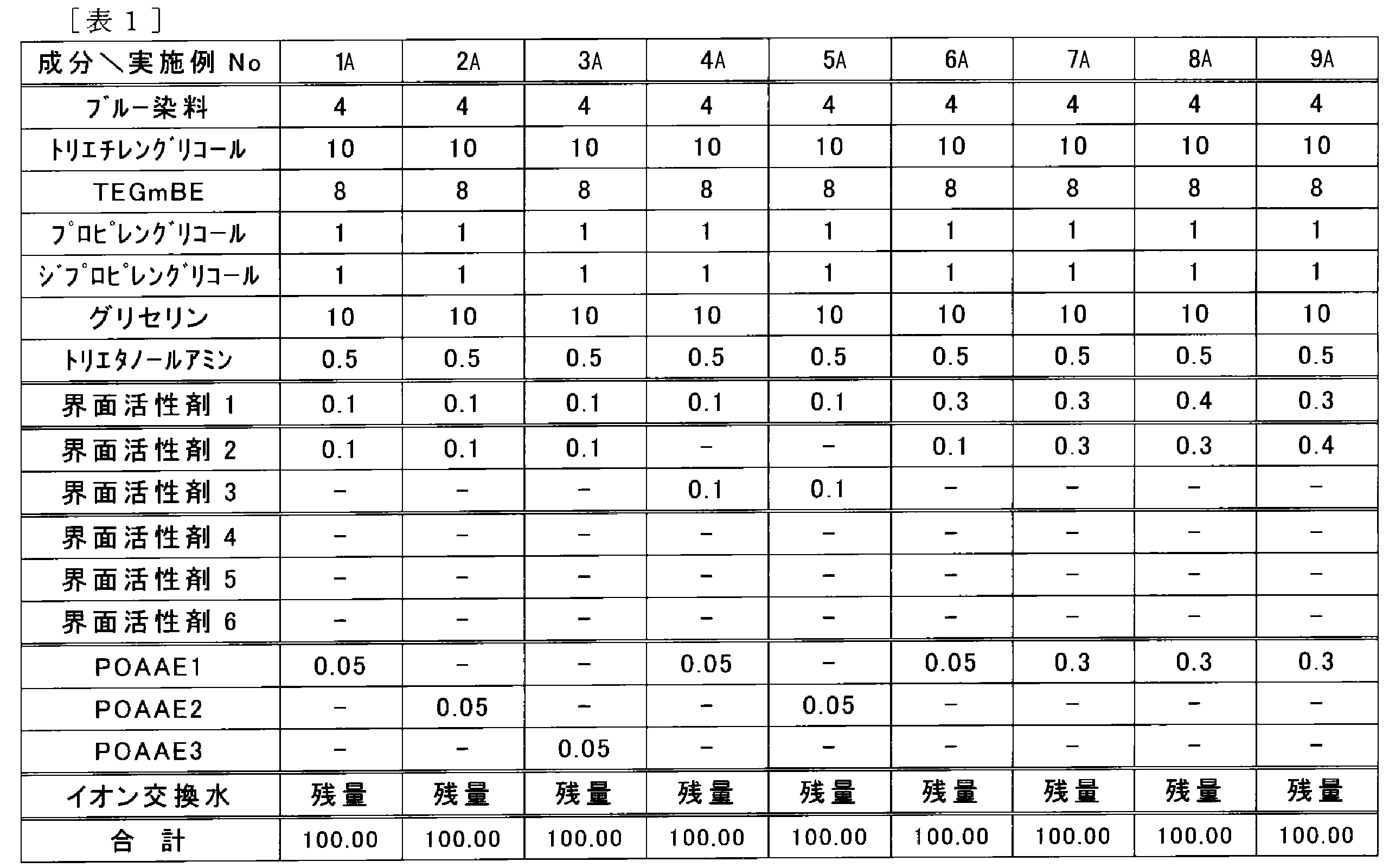
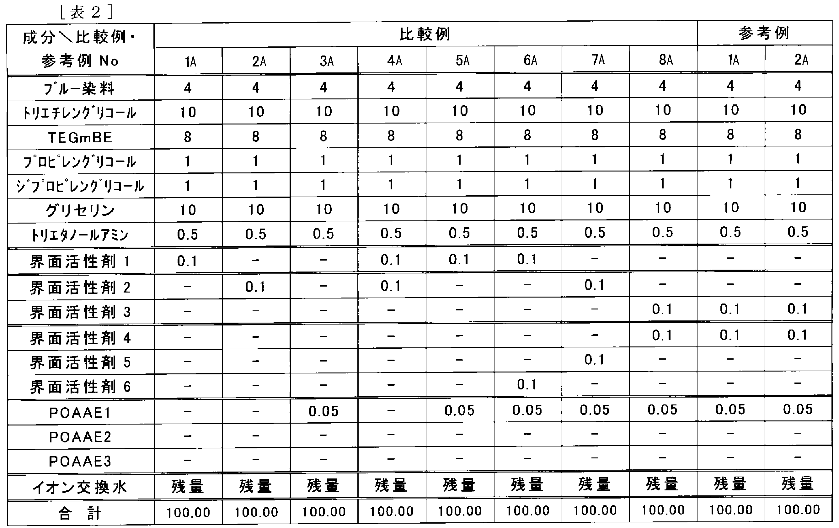
〔1A.インクの溶存窒素量の測定〕
Agilent Technologies製の6890N ネットワークGCを用いて溶存窒素量を測定した。測定結果を下記表3に示す。
ここで、脱気処理は、参考例の各インク組成物についてのみ行い、実施例及び比較例の各インク組成物については行わなかった。参考例における当該脱気処理は、市販されているチャンバー方式の真空脱気装置を用いて、脱気時間を調整したものである。これにより、溶存窒素量が互いに異なる各インクを作製した。
なお、下記表3中の「溶存窒素量」は、インク組成物中に溶存する窒素の量を表し、単位はppmである。
調製した各インク組成物について、材料成分が均一に溶解(分散)できているかどうか、目視観察を行った。
評価基準は以下のとおりである。評価結果を下記表3に示す。
○:インクの原料成分が均一に溶解(分散)しており、溶け残った浮遊物は観察されなかった。
×:インクの原料成分が溶解(分散)せずに、溶け残りが浮遊物として観察された。
調製した各インク組成物を、20ml容の蓋付きガラス瓶に取り分け、70℃で1週間放置した。インクの液面を観察し、浮遊物の有無を目視で確認した。さらに、孔径10μmのフィルターでインクをろ過したときに、捕集物(ろ集物)の有無を確認した。
評価基準は以下のとおりである。評価結果を下記表3に示す。
○:インク成分由来の浮遊物は観察されず、捕集物も得られなかった。
△:インク成分由来の浮遊物が観察されたが、捕集物は得られなかった(実用上の問題なし)。
×:捕集物が得られた。
調製した各インク組成物を、インクジェットプリンター(L100〔製品名〕、セイコーエプソン社製)のインクタンクに充填した。L100の定める初期充填シーケンスに従い、ヘッドへの初期充填動作を行った。この後、ヘッドの全ノズルからインクが吐出できるかどうかを確認するため、ノズルチェックを実施した。インクが吐出できないノズルがある場合には、ヘッドのクリーニング(ノズル内のインクの吸引)を行い、その後再度ノズルチェックを実施した。全ノズルからインクが吐出できるまでに要したクリーニングの回数に基づき、以下の評価基準により初期充填性を評価した。評価結果を下記表3に示す。
○:初期充填シーケンスのみで全ノズルから吐出した。
△:全ノズルからインクが吐出できるまでに要したクリーニング回数が1回であった。
×:全ノズルからインクが吐出できるまでに要したクリーニング回数が2回以上であった。
上記「4A.初期充填性の評価」によって、ヘッドの全ノズルからインクが吐出できることを確認した後、各インク組成物及びA4サイズの普通紙(P紙〔製品名〕、富士ゼロックス社製)を用いて、70%Dutyの画像を印刷することにより、連続印刷安定性の評価を行った。印刷枚数は、500枚の連続印刷を2回行い、合計で1,000枚とした。その後、ノズルチェックを実施し、ノズル抜けの本数に基づき、以下の評価基準により連続印刷安定性を評価した。評価結果を下記表3に示す。
○:ノズル抜けが発生した回数が1本以下であった。
△:ノズル抜けが発生した回数が2本であった。
×:ノズル抜けが発生した回数が3本以上であった。

[使用材料]
下記の実施例及び比較例において使用した主な材料は、以下の通りである。
〔顔料〕
・C.I.ダイレクトブルー199
〔界面活性剤〕
(1.主鎖の炭素数12以上のアセチレングリコールのアルキレンオキサイド付加物)
・界面活性剤1(主鎖の炭素数12、エチレンオキサイドの付加あり、2,5,8,11-テトラメチル-6-ドデシン-5,8-ジオールのエトキシレート)
(2.主鎖の炭素数10以上のアセチレングリコール)
・界面活性剤2(主鎖の炭素数12、エチレンオキサイドの付加なし、2,5,8,11-テトラメチル-6-ドデシン-5,8-ジオール)
・界面活性剤3(主鎖の炭素数10、エチレンオキサイドの付加なし、2,4,7,9-テトラメチル-5-デシン-4,7-ジオール)
(3.その他のアセチレングリコール系化合物)
・界面活性剤4(主鎖の炭素数10、エチレンオキサイドの付加モル数10。2,4,7,9-テトラメチル-5-デシン-4,7-ジオールのエトキシレート)
・界面活性剤5(主鎖の炭素数10、エチレンオキサイド付加モル数4。2,4,7,9-テトラメチル-5-デシン-4,7-ジオールのエトキシレート)
〔ポリオキシアルキレンアルキルエーテル〕
・ポリオキシアルキレンアルキルエーテル1(HLB値15.0、以下「POAAE1」という。)
なお、POAAE1の化学式を以下に示す。
RO(C2H4O)w(C3H6O)x(C2H4O)y(C3H6O)zH
上記化学式中、Rは炭素数12のアルキル、w+y=15、x+z=4である。
・ポリオキシアルキレンアルキルエーテル2(HLB値12.0、以下「POAAE2」という。)
なお、POAAE2の化学式を以下に示す。
RO(C2H4O)w(C3H6O)xH
上記化学式中、Rは炭素数12のアルキル、w=7、x=5である。
・ポリオキシアルキレンアルキルエーテル3(HLB値10.9、以下「POAAE3」という。)
なお、POAAE3の化学式を以下に示す。
RO(C2H4O)w(C3H6O)xH
上記化学式中、Rは炭素数12のアルキル、w=5、x=4である。
〔有機溶剤〕
・トリエチレングリコール
・トリエチレングリコールモノブチルエーテル(以下「TEGmBE」という。)
・プロピレングリコール
・ジプロピレングリコール
・グリセリン
・トリエタノールアミン
下記の表4及び表5に示す組成に従い、各成分の混合及び攪拌を行うことにより、各インクを調製した。また、各インクは、孔径1μmのメンブレンフィルターにて濾過することにより爽雑物を除いた。なお、下記の表4及び表5中、数値の単位は質量%であり、合計は100.00質量%である。
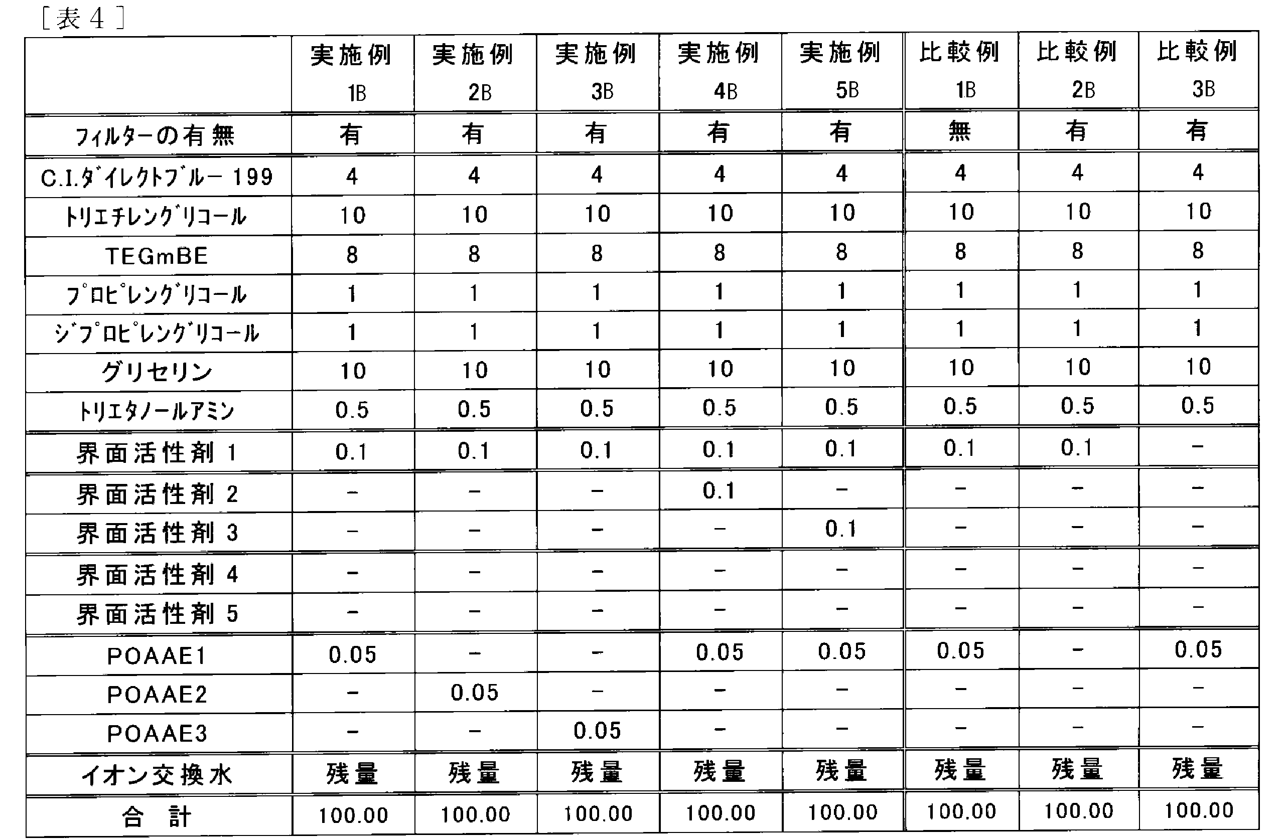
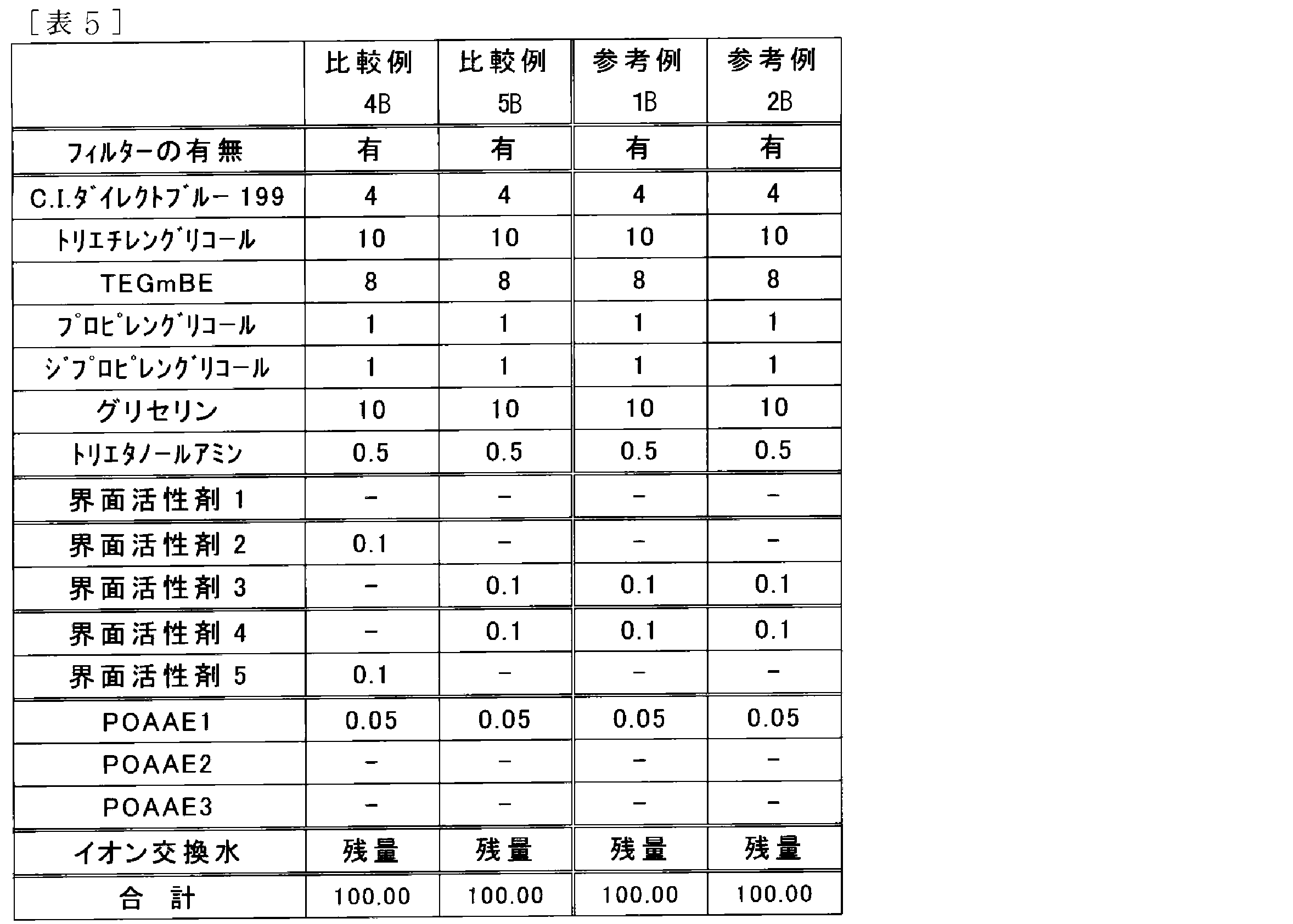
〔1B.インクの溶存窒素量の測定〕
Agilent Technologies製の6890N ネットワークGCを用いて溶存窒素量を測定した。測定結果を下記表3に示す。
ここで、脱気処理は、参考例1B~2Bの各インクについてのみ行い、実施例及び比較例の各インクについては行わなかった。参考例1B~2Bにおける当該脱気処理は、市販されているチャンバー方式の真空脱気装置を用いて、脱気時間を調整したものである。これにより、溶存窒素量が互いに異なるインクを作製した。
なお、下記表6中の「溶存窒素量」は、インク中に溶存する空気に含まれる窒素の量を表し、単位はppmである。
調製した各インクについて、材料成分が均一に溶解(分散)できているかどうか、目視観察を行った。
評価基準は以下のとおりである。評価結果を下記表6に示す。
○:インクの原料成分が均一に溶解(分散)しており、溶け残った浮遊物は観察されなかった。
×:インクの原料成分が溶解(分散)せずに、溶け残りが浮遊物として観察された。
調製した各インクを、20ml容の蓋付きガラス瓶に取り分け、70℃で1週間放置した。インクの液面を観察し、浮遊物の有無を目視で確認した。さらに、孔径10μmのフィルターでインクをろ過したときに、捕集物(ろ集物)の有無を確認した。
評価基準は以下のとおりである。評価結果を下記表6に示す。
○:浮遊物及び捕集物は共に確認されなかった。
×:浮遊物又は捕集物を確認した。
調製した各インクを、インクジェットプリンター(L100〔製品名〕、セイコーエプソン社製)のインクタンクに充填した。L100の定める初期充填シーケンスに従い、ヘッドへの初期充填動作を行った。この後、ヘッドの全ノズルからインクが吐出できるかどうかを確認するため、ノズルチェックを実施した(用いたノズルのノズル径は約22μmであった。)。インクが吐出できないノズルがある場合には、ヘッドのクリーニング(ノズル内のインクの吸引)を行い、その後再度ノズルチェックを実施した。全ノズルからインクが吐出できるまでに要したクリーニングの回数に基づき、以下の評価基準により初期充填性を評価した。評価結果を下記表6に示す。
○:初期充填シーケンスのみで全ノズルから吐出した。
△:全ノズルからインクが吐出できるまでに要したクリーニング回数が1回であった。
×:全ノズルからインクが吐出できるまでに要したクリーニング回数が2回以上であった。
上記「4B.初期充填性の評価」によって、ヘッドの全ノズルからインクが吐出できることを確認した後、各インク及びA4サイズの普通紙(P紙〔製品名〕、富士ゼロックス社製)を用いて、70%Dutyの画像を印刷することにより、連続印刷安定性の評価を行った(用いたノズルのノズル径は約22μmであった。)。印刷枚数は、500枚の連続印刷を2回行い、合計で1,000枚とした。その後、ノズルチェックを実施し、ノズル抜けの本数に基づき、以下の評価基準により連続印刷安定性を評価した。評価結果を下記表6に示す。
◎:ノズル抜けが発生した本数が0本であった。
○:ノズル抜けが発生した本数が1本であった。
△:ノズル抜けが発生した本数が2本であった。
×:ノズル抜けが発生した本数が3本以上であった。

Claims (13)
- 主鎖の炭素数が12以上であるアセチレングリコールのアルキレンオキサイド付加物(A)と、
主鎖の炭素数が10以上であるアセチレングリコール(B)と、
ポリオキシアルキレンアルキルエーテル(C)と、を含む、インクジェット記録用インク組成物。 - 前記ポリオキシアルキレンアルキルエーテル(C)のHLB値が12~16である、請求項1に記載のインクジェット記録用インク組成物。
- 前記アルキレンオキサイド付加物がエチレンオキサイド付加物である、請求項1に記載のインクジェット記録用インク組成物。
- ポリオキシアルキレンアルキルエーテル(C)の含有量と、主鎖の炭素数が12以上であるアセチレングリコールのアルキレンオキサイド付加物(A)及び主鎖の炭素数が10以上であるアセチレングリコール(B)の総含有量と、の質量比は、0.10:1.0~0.50:1.0の範囲である、請求項1に記載のインクジェット記録用インク組成物。
- 前記主鎖の炭素数が12以上であるアセチレングリコールのアルキレンオキサイド付加物(A)のHLB値が、8~15である、請求項1に記載のインクジェット記録用インク組成物。
- 前記主鎖の炭素数が10以上であるアセチレングリコール(B)のHLB値が、4以下である、請求項1に記載のインクジェット記録用インク組成物。
- 着色剤をさらに含む、請求項1に記載のインクジェット記録用インク組成物。
- 有機溶剤をさらに含む、請求項1に記載のインクジェット記録用インク組成物。
- 大気及びインクが接触可能な、請求項1に記載のインクを収容するインク収容容器と、
前記インクを吐出するプリントヘッドと、
前記インク収容容器及び前記プリントヘッドを接続し、前記インク収容容器から前記プリントヘッドへ前記インクが流れるインク供給路と、
前記インク供給路に設けられたフィルター(D)と、を備える、インク供給システム。 - 前記フィルターの平均孔径は、前記プリントヘッドのノズルのノズル径以下である、請求項9に記載のインク供給システム。
- 前記フィルター(D)が、前記インク供給路に複数設けられる、請求項9に記載のインク供給システム。
- 前記フィルター(D)の材質は樹脂である、請求項9に記載のインク供給システム。
- 請求項9に記載のインク供給システムを備え、
前記インク収容容器から前記プリントヘッドへ供給される前記インクを、該プリントヘッドから被記録媒体に向けて吐出し記録を行う、インクジェット記録装置。
Priority Applications (7)
| Application Number | Priority Date | Filing Date | Title |
|---|---|---|---|
| CN201380021108.2A CN104245860B (zh) | 2012-04-23 | 2013-03-12 | 喷墨记录用油墨组合物、油墨供给系统和喷墨记录装置 |
| US14/396,276 US9193882B2 (en) | 2012-04-23 | 2013-03-12 | Ink composition for ink jet recording, ink supply system, and ink jet recording apparatus |
| EP13781421.6A EP2843010B1 (en) | 2012-04-23 | 2013-03-12 | Ink composition for ink-jet recording, ink supply system, and ink-jet recording device |
| RU2014147004A RU2014147004A (ru) | 2012-04-23 | 2013-03-12 | Композиция краски для краскоструйной печати, подающая краску система и краскоструйное печатающее устройство |
| BR112014026604A BR112014026604A2 (pt) | 2012-04-23 | 2013-03-12 | composição de tinta para gravação por jato de tinta, sistema de fornecimento de tinta e aparelho para gravação por jato de tinta |
| HK15104457.1A HK1203994A1 (en) | 2012-04-23 | 2015-05-12 | Ink composition for ink-jet recording, ink supply system, and ink-jet recording device |
| US14/920,053 US9334412B2 (en) | 2012-04-23 | 2015-10-22 | Ink composition for ink jet recording, ink supply system, and ink jet recording apparatus |
Applications Claiming Priority (4)
| Application Number | Priority Date | Filing Date | Title |
|---|---|---|---|
| JP2012-097538 | 2012-04-23 | ||
| JP2012097540A JP5920572B2 (ja) | 2012-04-23 | 2012-04-23 | インク供給システム及びインクジェット記録装置 |
| JP2012097538A JP5939432B2 (ja) | 2012-04-23 | 2012-04-23 | インクジェット記録用インク組成物 |
| JP2012-097540 | 2012-04-23 |
Related Child Applications (2)
| Application Number | Title | Priority Date | Filing Date |
|---|---|---|---|
| US14/396,276 A-371-Of-International US9193882B2 (en) | 2012-04-23 | 2013-03-12 | Ink composition for ink jet recording, ink supply system, and ink jet recording apparatus |
| US14/920,053 Continuation US9334412B2 (en) | 2012-04-23 | 2015-10-22 | Ink composition for ink jet recording, ink supply system, and ink jet recording apparatus |
Publications (1)
| Publication Number | Publication Date |
|---|---|
| WO2013161410A1 true WO2013161410A1 (ja) | 2013-10-31 |
Family
ID=49482750
Family Applications (1)
| Application Number | Title | Priority Date | Filing Date |
|---|---|---|---|
| PCT/JP2013/056813 WO2013161410A1 (ja) | 2012-04-23 | 2013-03-12 | インクジェット記録用インク組成物、インク供給システム及びインクジェット記録装置 |
Country Status (7)
| Country | Link |
|---|---|
| US (2) | US9193882B2 (ja) |
| EP (1) | EP2843010B1 (ja) |
| CN (1) | CN104245860B (ja) |
| BR (1) | BR112014026604A2 (ja) |
| HK (1) | HK1203994A1 (ja) |
| RU (1) | RU2014147004A (ja) |
| WO (1) | WO2013161410A1 (ja) |
Cited By (2)
| Publication number | Priority date | Publication date | Assignee | Title |
|---|---|---|---|---|
| EP2889344A1 (en) * | 2013-12-25 | 2015-07-01 | Seiko Epson Corporation | Ink composition for ink jet recording |
| JP2016172336A (ja) * | 2015-03-16 | 2016-09-29 | セイコーエプソン株式会社 | インクジェット記録方法 |
Families Citing this family (18)
| Publication number | Priority date | Publication date | Assignee | Title |
|---|---|---|---|---|
| WO2012134486A1 (en) * | 2011-03-31 | 2012-10-04 | Hewlett-Packard Development Company, L.P. | Fluidic devices, bubble generators and fluid control methods |
| US20160200925A1 (en) * | 2015-01-08 | 2016-07-14 | Canon Kabushiki Kaisha | Image recording method, ink, and liquid composition |
| JP6604001B2 (ja) | 2015-02-24 | 2019-11-13 | セイコーエプソン株式会社 | インクジェットインク組成物及びインクジェット記録方法、インクセット |
| JP6604000B2 (ja) | 2015-02-24 | 2019-11-13 | セイコーエプソン株式会社 | インクジェットインク組成物及びインクジェット記録方法 |
| JP6477047B2 (ja) * | 2015-03-06 | 2019-03-06 | セイコーエプソン株式会社 | インク組成物及びインクセット |
| JP6812138B2 (ja) * | 2015-06-04 | 2021-01-13 | キヤノン株式会社 | インクジェット記録方法、及びインクジェット記録装置 |
| CN107011739B (zh) | 2016-01-27 | 2021-10-08 | 精工爱普生株式会社 | 非水系喷墨组合物 |
| CN107022243A (zh) | 2016-01-27 | 2017-08-08 | 精工爱普生株式会社 | 非水系喷墨组合物 |
| JP6846001B2 (ja) | 2016-06-14 | 2021-03-24 | セイコーエプソン株式会社 | インク組成物及び記録方法 |
| JP6977262B2 (ja) | 2016-12-29 | 2021-12-08 | セイコーエプソン株式会社 | インク組成物、インクセット |
| US10960674B2 (en) | 2017-02-28 | 2021-03-30 | Hewlett-Packard Development Company, L.P. | Reservoir and bubble structure |
| JP7342356B2 (ja) * | 2018-12-26 | 2023-09-12 | セイコーエプソン株式会社 | 流路構造体、液体吐出ユニットおよび液体吐出装置 |
| JP7282574B2 (ja) * | 2019-04-05 | 2023-05-29 | キヤノン株式会社 | インクジェット記録装置 |
| JP2021053956A (ja) | 2019-09-30 | 2021-04-08 | セイコーエプソン株式会社 | インクジェット記録装置、インクジェット記録方法、及びインク組成物 |
| JP7392359B2 (ja) | 2019-09-30 | 2023-12-06 | セイコーエプソン株式会社 | インクジェット記録装置、インクジェット記録方法、及びインク組成物 |
| JP7392358B2 (ja) | 2019-09-30 | 2023-12-06 | セイコーエプソン株式会社 | インクジェット記録装置、インクジェット記録方法、及びインク組成物 |
| JP7467862B2 (ja) * | 2019-09-30 | 2024-04-16 | セイコーエプソン株式会社 | インクジェット記録装置、インクジェット記録方法、及び水性インク組成物 |
| JP7408982B2 (ja) | 2019-09-30 | 2024-01-09 | セイコーエプソン株式会社 | インクジェット記録装置、及びインクジェット記録方法 |
Citations (8)
| Publication number | Priority date | Publication date | Assignee | Title |
|---|---|---|---|---|
| JPH11504874A (ja) | 1995-05-03 | 1999-05-11 | エンキャド インコーポレイテッド | 大容量インクタンクを備えるインクジェットプリンタ |
| JP2003127427A (ja) | 2001-10-24 | 2003-05-08 | Hewlett Packard Co <Hp> | インク送出システム |
| JP2003246952A (ja) * | 2002-02-26 | 2003-09-05 | Seiko Epson Corp | インクジェット用インク |
| JP2003253599A (ja) * | 2002-02-28 | 2003-09-10 | Nisshin Chem Ind Co Ltd | 水溶性界面活性剤組成物 |
| JP2004315739A (ja) * | 2003-04-18 | 2004-11-11 | Seiko Epson Corp | インク組成物及びこれを用いた記録方法、記録物 |
| JP2006095972A (ja) * | 2004-09-30 | 2006-04-13 | Seiko Epson Corp | インク供給機構、その機構を備えたインクジェット記録装置、およびインク組成物 |
| JP2007277330A (ja) * | 2006-04-04 | 2007-10-25 | Seiko Epson Corp | 水性インク組成物、これを用いたインクジェット記録方法及び記録物 |
| JP2011042104A (ja) | 2009-08-21 | 2011-03-03 | Konica Minolta Ij Technologies Inc | インクジェット画像形成方法 |
Family Cites Families (10)
| Publication number | Priority date | Publication date | Assignee | Title |
|---|---|---|---|---|
| CA2136373A1 (en) * | 1993-11-29 | 1995-05-30 | Steven W. Medina | Ethoxylated acetylenic glycols having low dynamic surface tension |
| US6890378B2 (en) | 2002-01-18 | 2005-05-10 | Seiko Epson Corporation | Inkjet ink |
| DE102004018337A1 (de) * | 2004-04-15 | 2005-12-08 | Pelikan Hardcopy Production Ag | Wässrige Ink Jet-Tinte |
| CN100595241C (zh) * | 2004-07-01 | 2010-03-24 | 通用株式会社 | 喷墨墨水及使用它的印刷方法 |
| US7429293B2 (en) | 2006-01-13 | 2008-09-30 | Xiaorong Cai | High gloss high gamut pigment inkjet ink |
| JP5089070B2 (ja) * | 2006-04-05 | 2012-12-05 | キヤノン株式会社 | インクジェット記録用インク及び記録方法 |
| JP2010023362A (ja) | 2008-07-22 | 2010-02-04 | Konica Minolta Holdings Inc | インクジェット記録方法 |
| KR102053474B1 (ko) * | 2012-03-06 | 2019-12-06 | 오세-테크놀로지스 베파우 | 잉크 조성물 |
| JP6037111B2 (ja) | 2012-11-02 | 2016-11-30 | セイコーエプソン株式会社 | インクジェット記録用のインク、インクジェット記録システム |
| JP6065622B2 (ja) * | 2013-02-05 | 2017-01-25 | セイコーエプソン株式会社 | インクジェット用インクセット及びインクジェット記録システム |
-
2013
- 2013-03-12 CN CN201380021108.2A patent/CN104245860B/zh active Active
- 2013-03-12 BR BR112014026604A patent/BR112014026604A2/pt not_active Application Discontinuation
- 2013-03-12 US US14/396,276 patent/US9193882B2/en active Active
- 2013-03-12 EP EP13781421.6A patent/EP2843010B1/en active Active
- 2013-03-12 RU RU2014147004A patent/RU2014147004A/ru not_active Application Discontinuation
- 2013-03-12 WO PCT/JP2013/056813 patent/WO2013161410A1/ja active Application Filing
-
2015
- 2015-05-12 HK HK15104457.1A patent/HK1203994A1/xx unknown
- 2015-10-22 US US14/920,053 patent/US9334412B2/en active Active
Patent Citations (8)
| Publication number | Priority date | Publication date | Assignee | Title |
|---|---|---|---|---|
| JPH11504874A (ja) | 1995-05-03 | 1999-05-11 | エンキャド インコーポレイテッド | 大容量インクタンクを備えるインクジェットプリンタ |
| JP2003127427A (ja) | 2001-10-24 | 2003-05-08 | Hewlett Packard Co <Hp> | インク送出システム |
| JP2003246952A (ja) * | 2002-02-26 | 2003-09-05 | Seiko Epson Corp | インクジェット用インク |
| JP2003253599A (ja) * | 2002-02-28 | 2003-09-10 | Nisshin Chem Ind Co Ltd | 水溶性界面活性剤組成物 |
| JP2004315739A (ja) * | 2003-04-18 | 2004-11-11 | Seiko Epson Corp | インク組成物及びこれを用いた記録方法、記録物 |
| JP2006095972A (ja) * | 2004-09-30 | 2006-04-13 | Seiko Epson Corp | インク供給機構、その機構を備えたインクジェット記録装置、およびインク組成物 |
| JP2007277330A (ja) * | 2006-04-04 | 2007-10-25 | Seiko Epson Corp | 水性インク組成物、これを用いたインクジェット記録方法及び記録物 |
| JP2011042104A (ja) | 2009-08-21 | 2011-03-03 | Konica Minolta Ij Technologies Inc | インクジェット画像形成方法 |
Cited By (3)
| Publication number | Priority date | Publication date | Assignee | Title |
|---|---|---|---|---|
| EP2889344A1 (en) * | 2013-12-25 | 2015-07-01 | Seiko Epson Corporation | Ink composition for ink jet recording |
| US9284465B2 (en) | 2013-12-25 | 2016-03-15 | Seiko Epson Corporation | Ink composition for ink jet recording |
| JP2016172336A (ja) * | 2015-03-16 | 2016-09-29 | セイコーエプソン株式会社 | インクジェット記録方法 |
Also Published As
| Publication number | Publication date |
|---|---|
| US20150085034A1 (en) | 2015-03-26 |
| RU2014147004A (ru) | 2016-06-10 |
| EP2843010B1 (en) | 2018-12-19 |
| EP2843010A1 (en) | 2015-03-04 |
| HK1203994A1 (en) | 2015-11-06 |
| US20160040022A1 (en) | 2016-02-11 |
| CN104245860A (zh) | 2014-12-24 |
| CN104245860B (zh) | 2016-10-12 |
| US9193882B2 (en) | 2015-11-24 |
| BR112014026604A2 (pt) | 2017-06-27 |
| EP2843010A4 (en) | 2015-12-30 |
| US9334412B2 (en) | 2016-05-10 |
Similar Documents
| Publication | Publication Date | Title |
|---|---|---|
| WO2013161410A1 (ja) | インクジェット記録用インク組成物、インク供給システム及びインクジェット記録装置 | |
| JP6065622B2 (ja) | インクジェット用インクセット及びインクジェット記録システム | |
| JP6037111B2 (ja) | インクジェット記録用のインク、インクジェット記録システム | |
| JP5939432B2 (ja) | インクジェット記録用インク組成物 | |
| JP2014079932A (ja) | メンテナンス液、インク供給システム、及びインクジェット記録装置 | |
| JP2017115075A (ja) | インクジェット記録用水性インクセット及びインクジェット記録装置 | |
| JP2010184424A (ja) | インクジェットプリンタ | |
| JP2017001391A (ja) | インクジェット記録方法、及びインクジェット記録装置 | |
| JP2018069652A (ja) | インクジェット記録方法 | |
| JP5920572B2 (ja) | インク供給システム及びインクジェット記録装置 | |
| JP2013212624A (ja) | 洗浄方法および洗浄装置 | |
| JP2012035471A (ja) | 液滴吐出装置 | |
| US11827033B2 (en) | Ink jet recording method and ink jet recording apparatus | |
| JP2016159450A (ja) | インクジェット記録装置及び堆積抑制方法 | |
| JP7214330B2 (ja) | インクジェット記録方法及びインクジェット記録装置 | |
| JP6443131B2 (ja) | 液体吐出記録装置及び液体回収方法 | |
| JP2017209785A (ja) | インクジェット記録方法及びインクジェット記録装置 | |
| JP6213113B2 (ja) | 液体吐出記録装置及び液体回収方法 | |
| JP6260935B2 (ja) | 液体吐出記録装置及び液体回収方法 | |
| JP2022022108A (ja) | インクジェット記録方法及びインクジェット記録装置 | |
| JP2020152106A (ja) | インクジェット記録方法及びインクジェット記録装置 | |
| JP2014151624A (ja) | 液体噴射装置、及び液体噴射装置のメンテナンス方法 | |
| JP2017081151A (ja) | インクジェット記録方法及びインクジェット記録装置 | |
| JP2016159451A (ja) | インクジェット記録装置及び堆積抑制方法 | |
| JP2006117772A (ja) | 記録液、液体カートリッジ、液体吐出装置及び液体吐出方法 |
Legal Events
| Date | Code | Title | Description |
|---|---|---|---|
| 121 | Ep: the epo has been informed by wipo that ep was designated in this application |
Ref document number: 13781421 Country of ref document: EP Kind code of ref document: A1 |
|
| WWE | Wipo information: entry into national phase |
Ref document number: 14396276 Country of ref document: US |
|
| NENP | Non-entry into the national phase |
Ref country code: DE |
|
| WWE | Wipo information: entry into national phase |
Ref document number: 2013781421 Country of ref document: EP |
|
| ENP | Entry into the national phase |
Ref document number: 2014147004 Country of ref document: RU Kind code of ref document: A |
|
| REG | Reference to national code |
Ref country code: BR Ref legal event code: B01A Ref document number: 112014026604 Country of ref document: BR |
|
| ENP | Entry into the national phase |
Ref document number: 112014026604 Country of ref document: BR Kind code of ref document: A2 Effective date: 20141023 |