WO2013153864A1 - Dispositif de production de plasma, dispositif de dépôt en phase vapeur et procédé de dépôt en phase vapeur - Google Patents
Dispositif de production de plasma, dispositif de dépôt en phase vapeur et procédé de dépôt en phase vapeur Download PDFInfo
- Publication number
- WO2013153864A1 WO2013153864A1 PCT/JP2013/055230 JP2013055230W WO2013153864A1 WO 2013153864 A1 WO2013153864 A1 WO 2013153864A1 JP 2013055230 W JP2013055230 W JP 2013055230W WO 2013153864 A1 WO2013153864 A1 WO 2013153864A1
- Authority
- WO
- WIPO (PCT)
- Prior art keywords
- plasma
- magnetic flux
- chamber
- vapor deposition
- coil
- Prior art date
Links
- 238000000034 method Methods 0.000 title claims abstract description 14
- 238000007740 vapor deposition Methods 0.000 title claims description 29
- 230000004907 flux Effects 0.000 claims abstract description 53
- 230000005284 excitation Effects 0.000 claims description 29
- 230000008020 evaporation Effects 0.000 claims description 4
- 238000001704 evaporation Methods 0.000 claims description 4
- 230000000737 periodic effect Effects 0.000 claims description 2
- 238000000151 deposition Methods 0.000 description 16
- 230000008021 deposition Effects 0.000 description 15
- BGPVFRJUHWVFKM-UHFFFAOYSA-N N1=C2C=CC=CC2=[N+]([O-])C1(CC1)CCC21N=C1C=CC=CC1=[N+]2[O-] Chemical compound N1=C2C=CC=CC2=[N+]([O-])C1(CC1)CCC21N=C1C=CC=CC1=[N+]2[O-] BGPVFRJUHWVFKM-UHFFFAOYSA-N 0.000 description 12
- 239000011521 glass Substances 0.000 description 11
- 239000000758 substrate Substances 0.000 description 11
- 230000008859 change Effects 0.000 description 4
- 230000007547 defect Effects 0.000 description 4
- 230000015572 biosynthetic process Effects 0.000 description 3
- 238000013021 overheating Methods 0.000 description 3
- 230000001360 synchronised effect Effects 0.000 description 3
- XKRFYHLGVUSROY-UHFFFAOYSA-N Argon Chemical compound [Ar] XKRFYHLGVUSROY-UHFFFAOYSA-N 0.000 description 2
- 238000010586 diagram Methods 0.000 description 2
- 230000000694 effects Effects 0.000 description 2
- 239000007789 gas Substances 0.000 description 2
- 239000000463 material Substances 0.000 description 2
- 239000002184 metal Substances 0.000 description 2
- 239000002994 raw material Substances 0.000 description 2
- 230000004044 response Effects 0.000 description 2
- 230000009471 action Effects 0.000 description 1
- 230000003213 activating effect Effects 0.000 description 1
- 238000013459 approach Methods 0.000 description 1
- 229910052786 argon Inorganic materials 0.000 description 1
- 230000002500 effect on skin Effects 0.000 description 1
- 230000002708 enhancing effect Effects 0.000 description 1
- 150000002500 ions Chemical class 0.000 description 1
- 230000008018 melting Effects 0.000 description 1
- 238000002844 melting Methods 0.000 description 1
- 230000008569 process Effects 0.000 description 1
- 230000001737 promoting effect Effects 0.000 description 1
- 238000004544 sputter deposition Methods 0.000 description 1
- 238000004804 winding Methods 0.000 description 1
Images
Classifications
-
- H—ELECTRICITY
- H05—ELECTRIC TECHNIQUES NOT OTHERWISE PROVIDED FOR
- H05H—PLASMA TECHNIQUE; PRODUCTION OF ACCELERATED ELECTRICALLY-CHARGED PARTICLES OR OF NEUTRONS; PRODUCTION OR ACCELERATION OF NEUTRAL MOLECULAR OR ATOMIC BEAMS
- H05H1/00—Generating plasma; Handling plasma
- H05H1/24—Generating plasma
- H05H1/48—Generating plasma using an arc
- H05H1/50—Generating plasma using an arc and using applied magnetic fields, e.g. for focusing or rotating the arc
-
- H—ELECTRICITY
- H01—ELECTRIC ELEMENTS
- H01J—ELECTRIC DISCHARGE TUBES OR DISCHARGE LAMPS
- H01J37/00—Discharge tubes with provision for introducing objects or material to be exposed to the discharge, e.g. for the purpose of examination or processing thereof
- H01J37/32—Gas-filled discharge tubes
- H01J37/32431—Constructional details of the reactor
- H01J37/3266—Magnetic control means
-
- C—CHEMISTRY; METALLURGY
- C23—COATING METALLIC MATERIAL; COATING MATERIAL WITH METALLIC MATERIAL; CHEMICAL SURFACE TREATMENT; DIFFUSION TREATMENT OF METALLIC MATERIAL; COATING BY VACUUM EVAPORATION, BY SPUTTERING, BY ION IMPLANTATION OR BY CHEMICAL VAPOUR DEPOSITION, IN GENERAL; INHIBITING CORROSION OF METALLIC MATERIAL OR INCRUSTATION IN GENERAL
- C23C—COATING METALLIC MATERIAL; COATING MATERIAL WITH METALLIC MATERIAL; SURFACE TREATMENT OF METALLIC MATERIAL BY DIFFUSION INTO THE SURFACE, BY CHEMICAL CONVERSION OR SUBSTITUTION; COATING BY VACUUM EVAPORATION, BY SPUTTERING, BY ION IMPLANTATION OR BY CHEMICAL VAPOUR DEPOSITION, IN GENERAL
- C23C14/00—Coating by vacuum evaporation, by sputtering or by ion implantation of the coating forming material
- C23C14/22—Coating by vacuum evaporation, by sputtering or by ion implantation of the coating forming material characterised by the process of coating
- C23C14/24—Vacuum evaporation
- C23C14/32—Vacuum evaporation by explosion; by evaporation and subsequent ionisation of the vapours, e.g. ion-plating
-
- C—CHEMISTRY; METALLURGY
- C23—COATING METALLIC MATERIAL; COATING MATERIAL WITH METALLIC MATERIAL; CHEMICAL SURFACE TREATMENT; DIFFUSION TREATMENT OF METALLIC MATERIAL; COATING BY VACUUM EVAPORATION, BY SPUTTERING, BY ION IMPLANTATION OR BY CHEMICAL VAPOUR DEPOSITION, IN GENERAL; INHIBITING CORROSION OF METALLIC MATERIAL OR INCRUSTATION IN GENERAL
- C23C—COATING METALLIC MATERIAL; COATING MATERIAL WITH METALLIC MATERIAL; SURFACE TREATMENT OF METALLIC MATERIAL BY DIFFUSION INTO THE SURFACE, BY CHEMICAL CONVERSION OR SUBSTITUTION; COATING BY VACUUM EVAPORATION, BY SPUTTERING, BY ION IMPLANTATION OR BY CHEMICAL VAPOUR DEPOSITION, IN GENERAL
- C23C14/00—Coating by vacuum evaporation, by sputtering or by ion implantation of the coating forming material
- C23C14/22—Coating by vacuum evaporation, by sputtering or by ion implantation of the coating forming material characterised by the process of coating
- C23C14/48—Ion implantation
Definitions
- the present invention relates to a plasma generating apparatus, a vapor deposition apparatus and a vapor deposition method.
- a vapor deposition apparatus that performs a plasma assist method of forming a plasma to promote vapor deposition.
- the plasma assist method when the deposition target such as a glass substrate is disposed near the plasma, the deposition target is overheated to cause ion sputtering on the surface thereof, which may cause defects in the film formed by deposition.
- Plasma guns generally include focusing coils to create a magnetic flux that guides the emitted electrons. Therefore, in the vapor deposition apparatus described in Patent Document 1 and Patent Document 2, a magnet is used to bend the magnetic flux formed by the focusing coil or to form a synthesized magnetic field which is bent, and plasma near the crucible of the vapor deposition material To be formed.
- a magnet is used to bend the magnetic flux formed by the focusing coil or to form a synthesized magnetic field which is bent, and plasma near the crucible of the vapor deposition material To be formed.
- the distance between the deposition target and the plasma is long, there is a problem that the activity of the evaporated raw material is reduced and the film quality is deteriorated.
- the present invention provides a plasma generating apparatus capable of forming a plasma suitable for the plasma assist method, and an evaporation apparatus capable of forming high quality films without causing defects in the deposited film by the plasma assist method
- An object is to provide a deposition method.
- a plasma generating apparatus is disposed so as to face a chamber, the inside of the chamber, and forms a cathode that emits electrons and a magnetic flux that guides the electrons emitted by the cathode.
- a focusing coil is provided, a plasma gun, and an auxiliary magnet for forming a magnetic flux in the chamber, and an exciting current in which the direction of the magnetic flux changes is applied to the focusing coil.
- the path of the combined magnetic flux of the magnetic flux formed by the focusing coil and the magnetic flux formed by the auxiliary magnet changes with the current change of the excitation current.
- This causes the range in which the plasma is formed to move, typically to bend or elongate the range in which the plasma is formed to move closer to or away from the auxiliary magnet. This makes it possible to move the plasma and avoid problems such as overheating of the deposition object caused by fixing the range of the plasma.
- the plasma gun is a pressure gradient type plasma gun including a first electrode and a second electrode between the cathode and the focusing coil, and the second electrode is an internal
- An in-electrode coil may be disposed, and the plasma generator may apply an in-electrode current that fluctuates in synchronization with the excitation current to the in-electrode coil.
- the direction of the magnetic flux formed by the coil in the electrode and the direction of the magnetic flux formed by the focusing coil are synchronized, so that electrons emitted from the cathode can be easily captured by the magnetic flux formed by the focusing coil. Movement is stable. For this reason, the tolerance of the change of the excitation current which generates the plasma stably is high, and the movement of the plasma generation range with respect to the current fluctuation is quickly followed.
- the excitation current and the in-pole current have similar periodic waveforms in the same phase, and form magnetic flux of the same polarity in the excitation coil and the in-electrode coil. May be
- the auxiliary magnet may be disposed outside the chamber opposite to the plasma gun such that the direction of the magnetic pole intersects the axis of the plasma gun.
- the auxiliary magnet can bend the synthetic magnetic flux out of the axis of the plasma gun, so that the plasma generation range can be easily rocked.
- the 1st aspect of the vapor deposition apparatus by this invention shall equip any one of the said plasma generation apparatus.
- a second aspect of the vapor deposition apparatus is a vapor deposition apparatus that performs deposition by forming plasma by emitting electrons into a chamber that holds an object to be vapor deposited, the electrons emitted into the chamber The deposition is performed while changing the path of the magnetic flux guiding the.
- plasma is formed by emitting electrons into a chamber holding an object to be vapor deposited, and vapor deposition is performed while changing a path of magnetic flux guiding electrons emitted into the chamber.
- vapor deposition apparatuses and vapor deposition methods it is possible to improve the quality of the vapor deposition film by enhancing the activity of the evaporated raw material while preventing the occurrence of defects of the vapor deposition film due to the overheating of the deposition object.
- the generation range of plasma can be moved and the action of plasma can be adjusted by changing the path of magnetic flux guiding electrons.
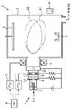
- FIG. 1 shows the configuration of a vapor deposition apparatus 1 according to a first embodiment of the present invention.
- the deposition apparatus 1 includes a chamber 2 capable of evacuating the inside, a pressure gradient plasma gun 3 disposed so as to look at the inside of the chamber 2 from an opening provided on a side wall of the chamber 2, and a plasma gun 3 of the chamber 2.
- an auxiliary magnet 4 consisting of a permanent magnet disposed on the outside of the opposite side wall.
- the chamber 2 can hold the glass substrate 5 which is a body to be deposited on the surface of which the metal is to be deposited, at the top of the internal space, and a crucible 6 for melting the deposition material at the bottom.
- the plasma gun 3 comprises a cathode 7 emitting electrons, a first electrode 8 and a second electrode 9 forming a potential gradient along the orbit of the electrons, a feedback electrode 10 recovering electrons emitted by the cathode 7, and a cathode And a focusing coil 11 for forming a magnetic flux for guiding the emitted electrons.
- the first electrode 8 is a hollow annular electrode in which the permanent magnet 12 is accommodated.
- the second electrode 9 is a hollow annular electrode in which an inner electrode coil 13 made of an air core coil is accommodated.
- the plasma gun 3 injects, for example, a gas such as argon, which is ionized to form a plasma, through the centers of the cathode 7, the first electrode 8, the second electrode 9, the return electrode 10, and the focusing coil 11. ing.
- the plasma gun 3 comprises an inverter, an intrapole excitation power supply 14 for applying an intrapole current which is an alternating current to the intrapole coil 13 of the second electrode 9, and an inverter. And a controller 16 for controlling the intra-pole excitation power supply 14 and the convergence excitation power supply 15.
- the in-pole excitation power supply 14 and the convergent excitation power supply 15 have the same winding direction, that is, the direction of the magnetic flux generated with respect to the applied current is the same. Further, in the present embodiment, the control device 16 causes the intrapole excitation power supply 14 and the convergent excitation power supply 15 to output synchronized sine wave currents having the same frequency and the same phase.
- the auxiliary magnet 4 is shifted from the central axis of the plasma gun 3 so that the direction between the poles is orthogonal to the central axis of the plasma gun 3, specifically, the south pole faces the direction of the central axis of the plasma gun 3 Are arranged.
- the magnetic flux formed by the focusing coil 11 is attracted to the auxiliary magnet 4. That is, the combined magnetic field of the magnetic flux formed by the focusing coil 11 and the magnetic flux formed by the auxiliary magnet 4 is curved so as to deviate from the central axis of the plasma gun 3 toward the auxiliary magnet 4. Since the electrons emitted from the plasma gun 3 move so as to be caught in the magnetic flux, the range in which the gas injected from the plasma gun 3 is ionized to form a plasma is also as shown by the alternate long and short dashed line A1. It curves to the magnet 4 side.
- the magnetic flux formed by the focusing coil 11 and the magnetic flux formed by the auxiliary magnet 4 repel each other, so electrons emitted from the plasma gun 3 It can not form a continuous magnetic flux to guide. For this reason, the electrons go straight along the central axis of the plasma gun 3 substantially without being guided by the magnetic flux, and in a region substantially along the central axis of the plasma gun 3 as in the range A2 illustrated by the two-dot chain line. Form a plasma.
- the range in which plasma is formed may be separated from the auxiliary magnet 4 depending on the balance between the magnetic flux formed by the focusing coil 11 and the magnetic flux formed by the auxiliary magnet 4.
- the range in which the plasma is formed oscillates in synchronization with the excitation current. That is, the plasma in the chamber 2 repeatedly approaches and separates from the glass substrate 5 in the same cycle as the excitation current applied to the focusing coil 11.
- the vapor deposition apparatus 1 periodically separates the plasma from the glass substrate 5 to reduce the amount of heat that the glass substrate 5 receives from the plasma. As a result, defects in the vapor deposition film that may occur due to an excessive increase in the temperature of the glass substrate 5 are prevented. At the same time, the film quality and the film formation efficiency can be improved by periodically approaching the glass substrate 5 with plasma activating the evaporated deposition source molecules.
- the plasma gun 3 applies the intrapole current synchronized with the excitation current to the intrapole coil 13 of the second electrode 9, the magnetic flux formed by the intrapole coil 13 and the magnetic flux formed by the focusing coil 11 Are integrated to form a combined magnetic flux passing through the inside of the plasma gun 3. For this reason, the electrons emitted from the cathode 7 are trapped by the magnetic flux formed by the focusing coil 11 and the intrapolar coil 13 in the plasma gun 3, and even after being emitted into the chamber 2, the magnetic flux of the focusing coil 11.
- the moving path of electrons can be made to follow the response of the change of the magnetic flux of the focusing coil 11 with good response, and the formation range of plasma can be stably rocked.
- the temperature of the cathode 7 is low, and electrons are unstable. Therefore, the excitation current and the intrapole current are used as a direct current, and the temperature of the cathode 7 rises to release stable thermal electrons. It is desirable to change the excitation current after the state is reached.
- the controller 16 swings the plasma by changing the output waveforms of the intrapole excitation power supply 14 and the convergent excitation power supply 15 or changing the frequency in order to adjust the deposition conditions.
- the range or swing cycle may be adjusted.
- the frequency of the intrapole current and the excitation current is high, the loss in the focusing coil 11 and the intrapole coil 13 increases due to the skin effect, so it is preferable to set the upper limit of these frequencies to about several hundred Hz.
- phase of the intrapole current applied to the intrapole coil 13 and the phase of the excitation current applied to the focusing coil 11 may be slightly shifted in consideration of the influence of an external magnetic field or the like. Further, for the sake of simplicity, the same power supply may be used to apply current to the focusing coil 11 and the inner coil 13.
- the auxiliary magnet 4 is preferably disposed outside the chamber because it loses the magnetic force when heated to the Curie temperature or higher, but may be disposed inside the chamber, even if the auxiliary magnet 4 is cooled. Good.
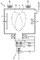
- FIG. 2 shows a vapor deposition apparatus 1a according to a second embodiment of the present invention.
- the same components as those in the first embodiment are denoted by the same reference numerals, and redundant description will be omitted.
- the plasma gun 3a of this embodiment is such that only a direct current is applied to the focusing coil 11 and the intrapole coil 13 as in the prior art.
- electrons emitted from the focusing coil 11 are detected by the two auxiliary magnets 4a and 4b disposed outside the chamber 2 opposite to the plasma gun 3. It is designed to move the path of the generated magnetic flux for guiding.
- the auxiliary magnets 4a and 4b are electromagnets, and are disposed on the opposite side to the glass substrate 5 and near the glass substrate 5 with the central axis of the plasma gun 3a interposed therebetween.
- the auxiliary magnets 4a and 4b are adapted to be applied with an auxiliary current which is periodically fluctuated by, for example, a power supply (not shown) and which has a phase difference of 90 °. That is, in the present embodiment, the synthetic magnetic flux of the convergent coil 11 and the auxiliary magnets 4a and 4b is oscillated by periodically changing the magnetic flux generated by the two auxiliary magnets 4a and 4b.
- the path of the magnetic flux for guiding the electrons emitted by the plasma gun 3a oscillates in the chamber 2, so that the glass substrate 5 can be prevented from overheating and the evaporated metal molecules can be activated.
- the magnetic flux may be oscillated by any one of the auxiliary magnets 4a and 4b, and a large number of auxiliary magnets may be used.
- the phase difference or the waveform of the auxiliary current applied to the auxiliary magnets 4a and 4b may be changed to adjust the condition of the deposition.
- the auxiliary magnet made of a permanent magnet may be moved mechanically.
- the present invention can also be combined with plasma density control by upslope and downslope of cathode output, etc., for adjustment of deposition conditions, high quality deposition can be achieved by wider setting conditions. .
- the present invention can be widely applied to apparatuses and methods for promoting processes using plasma as well as vapor deposition.
Landscapes
- Chemical & Material Sciences (AREA)
- Engineering & Computer Science (AREA)
- Plasma & Fusion (AREA)
- Physics & Mathematics (AREA)
- Organic Chemistry (AREA)
- Metallurgy (AREA)
- Mechanical Engineering (AREA)
- Materials Engineering (AREA)
- Chemical Kinetics & Catalysis (AREA)
- Analytical Chemistry (AREA)
- Spectroscopy & Molecular Physics (AREA)
- Plasma Technology (AREA)
- Physical Vapour Deposition (AREA)
Abstract
Priority Applications (4)
| Application Number | Priority Date | Filing Date | Title |
|---|---|---|---|
| US14/117,346 US20140158047A1 (en) | 2012-04-09 | 2013-02-27 | Plasma generation apparatus, deposition apparatus, and deposition method |
| CN201380001628.7A CN103597913B (zh) | 2012-04-09 | 2013-02-27 | 等离子体发生装置、以及蒸镀装置和蒸镀方法 |
| KR1020137031520A KR101953930B1 (ko) | 2012-04-09 | 2013-02-27 | 플라즈마 발생 장치 및 증착 장치 |
| EP13776393.4A EP2838324A4 (fr) | 2012-04-09 | 2013-02-27 | Dispositif de production de plasma, dispositif de dépôt en phase vapeur et procédé de dépôt en phase vapeur |
Applications Claiming Priority (2)
| Application Number | Priority Date | Filing Date | Title |
|---|---|---|---|
| JP2012088547A JP5968666B2 (ja) | 2012-04-09 | 2012-04-09 | プラズマ発生装置および蒸着装置 |
| JP2012-088547 | 2012-04-09 |
Publications (1)
| Publication Number | Publication Date |
|---|---|
| WO2013153864A1 true WO2013153864A1 (fr) | 2013-10-17 |
Family
ID=49327443
Family Applications (1)
| Application Number | Title | Priority Date | Filing Date |
|---|---|---|---|
| PCT/JP2013/055230 WO2013153864A1 (fr) | 2012-04-09 | 2013-02-27 | Dispositif de production de plasma, dispositif de dépôt en phase vapeur et procédé de dépôt en phase vapeur |
Country Status (7)
| Country | Link |
|---|---|
| US (1) | US20140158047A1 (fr) |
| EP (1) | EP2838324A4 (fr) |
| JP (1) | JP5968666B2 (fr) |
| KR (1) | KR101953930B1 (fr) |
| CN (1) | CN103597913B (fr) |
| TW (1) | TWI604077B (fr) |
| WO (1) | WO2013153864A1 (fr) |
Families Citing this family (5)
| Publication number | Priority date | Publication date | Assignee | Title |
|---|---|---|---|---|
| EP3314988B1 (fr) * | 2015-06-23 | 2020-06-17 | Aurora Labs Ltd | Appareil de propagation de particules entraînées par plasma et procédé de pompage |
| CN113056083A (zh) * | 2019-12-26 | 2021-06-29 | 上海宏澎能源科技有限公司 | 等离子束发生装置 |
| CN113365402B (zh) * | 2020-03-06 | 2023-04-07 | 上海宏澎能源科技有限公司 | 限制等离子束的装置 |
| CN114442437B (zh) * | 2020-10-30 | 2024-05-17 | 上海宏澎能源科技有限公司 | 光源装置 |
| CN114921764B (zh) * | 2022-06-28 | 2023-09-22 | 松山湖材料实验室 | 一种用于高功率脉冲磁控溅射的装置及方法 |
Citations (5)
| Publication number | Priority date | Publication date | Assignee | Title |
|---|---|---|---|---|
| JPH06264225A (ja) * | 1993-03-12 | 1994-09-20 | Ulvac Japan Ltd | イオンプレーティング装置 |
| JPH0776770A (ja) | 1993-09-10 | 1995-03-20 | A G Technol Kk | 蒸着装置 |
| JPH10237635A (ja) * | 1997-02-28 | 1998-09-08 | Sumitomo Heavy Ind Ltd | プラズマビームの偏り修正機構を備えた真空成膜装置 |
| JP2001295031A (ja) | 2000-04-14 | 2001-10-26 | Sumitomo Heavy Ind Ltd | 成膜装置及び方法 |
| JP2005116217A (ja) * | 2003-10-03 | 2005-04-28 | Tohoku Univ | プラズマ制御方法、及びプラズマ制御装置 |
Family Cites Families (18)
| Publication number | Priority date | Publication date | Assignee | Title |
|---|---|---|---|---|
| WO1986006922A1 (fr) * | 1985-05-09 | 1986-11-20 | The Commonwealth Of Australia | Generateur de plasma |
| JPH0215166A (ja) * | 1988-07-04 | 1990-01-18 | Kawasaki Steel Corp | イオンプレーティング装置 |
| JPH0222464A (ja) * | 1988-07-12 | 1990-01-25 | Raimuzu:Kk | イオンプレーティング装置 |
| JPH04329637A (ja) * | 1991-05-01 | 1992-11-18 | Fuji Electric Co Ltd | 絶縁膜の製造方法 |
| US5397956A (en) * | 1992-01-13 | 1995-03-14 | Tokyo Electron Limited | Electron beam excited plasma system |
| JPH0765170B2 (ja) * | 1992-01-30 | 1995-07-12 | 中外炉工業株式会社 | 薄膜形成装置におけるプラズマ走査装置 |
| JPH07254315A (ja) * | 1994-03-14 | 1995-10-03 | Nippon Sheet Glass Co Ltd | 被膜の形成方法 |
| US5677012A (en) * | 1994-12-28 | 1997-10-14 | Sumitomo Heavy Industries, Ltd. | Plasma processing method and plasma processing apparatus |
| JP4287936B2 (ja) * | 1999-02-01 | 2009-07-01 | 中外炉工業株式会社 | 真空成膜装置 |
| US7300559B2 (en) * | 2000-04-10 | 2007-11-27 | G & H Technologies Llc | Filtered cathodic arc deposition method and apparatus |
| JP4627365B2 (ja) * | 2000-11-17 | 2011-02-09 | 中外炉工業株式会社 | 圧力勾配型プラズマ発生装置の始動方法 |
| JP2003008197A (ja) * | 2001-06-20 | 2003-01-10 | Fujitsu Ten Ltd | 基板加熱装置 |
| US7033462B2 (en) * | 2001-11-30 | 2006-04-25 | Nissin Electric Co., Ltd. | Vacuum arc vapor deposition process and apparatus |
| JP3744467B2 (ja) * | 2002-06-04 | 2006-02-08 | 日新電機株式会社 | 真空アーク蒸着方法及びその装置 |
| JP4003448B2 (ja) * | 2001-11-30 | 2007-11-07 | 日新電機株式会社 | 真空アーク蒸着方法及びその装置 |
| JP2004010920A (ja) * | 2002-06-04 | 2004-01-15 | Nissin Electric Co Ltd | 真空アーク蒸着装置 |
| KR100606451B1 (ko) * | 2004-06-16 | 2006-08-01 | 송석균 | 상압 플라즈마 발생장치 |
| JP2008038197A (ja) | 2006-08-04 | 2008-02-21 | Shin Meiwa Ind Co Ltd | プラズマ成膜装置 |
-
2012
- 2012-04-09 JP JP2012088547A patent/JP5968666B2/ja not_active Expired - Fee Related
-
2013
- 2013-02-27 US US14/117,346 patent/US20140158047A1/en not_active Abandoned
- 2013-02-27 KR KR1020137031520A patent/KR101953930B1/ko active Active
- 2013-02-27 WO PCT/JP2013/055230 patent/WO2013153864A1/fr active Application Filing
- 2013-02-27 EP EP13776393.4A patent/EP2838324A4/fr not_active Withdrawn
- 2013-02-27 CN CN201380001628.7A patent/CN103597913B/zh not_active Expired - Fee Related
- 2013-04-01 TW TW102111668A patent/TWI604077B/zh not_active IP Right Cessation
Patent Citations (5)
| Publication number | Priority date | Publication date | Assignee | Title |
|---|---|---|---|---|
| JPH06264225A (ja) * | 1993-03-12 | 1994-09-20 | Ulvac Japan Ltd | イオンプレーティング装置 |
| JPH0776770A (ja) | 1993-09-10 | 1995-03-20 | A G Technol Kk | 蒸着装置 |
| JPH10237635A (ja) * | 1997-02-28 | 1998-09-08 | Sumitomo Heavy Ind Ltd | プラズマビームの偏り修正機構を備えた真空成膜装置 |
| JP2001295031A (ja) | 2000-04-14 | 2001-10-26 | Sumitomo Heavy Ind Ltd | 成膜装置及び方法 |
| JP2005116217A (ja) * | 2003-10-03 | 2005-04-28 | Tohoku Univ | プラズマ制御方法、及びプラズマ制御装置 |
Also Published As
| Publication number | Publication date |
|---|---|
| JP5968666B2 (ja) | 2016-08-10 |
| CN103597913B (zh) | 2016-09-14 |
| KR101953930B1 (ko) | 2019-03-04 |
| EP2838324A4 (fr) | 2015-09-23 |
| JP2013218881A (ja) | 2013-10-24 |
| EP2838324A1 (fr) | 2015-02-18 |
| KR20140143072A (ko) | 2014-12-15 |
| TWI604077B (zh) | 2017-11-01 |
| CN103597913A (zh) | 2014-02-19 |
| TW201348480A (zh) | 2013-12-01 |
| US20140158047A1 (en) | 2014-06-12 |
Similar Documents
| Publication | Publication Date | Title |
|---|---|---|
| WO2013153864A1 (fr) | Dispositif de production de plasma, dispositif de dépôt en phase vapeur et procédé de dépôt en phase vapeur | |
| EP2639330B1 (fr) | Procédé de transport de plasma à arc sous vide et dispositif de mise en oeuvre | |
| JP4491132B2 (ja) | プラズマ処理装置 | |
| TWI584331B (zh) | 用於產生帶電粒子束之電漿源裝置及方法 | |
| JPH072988B2 (ja) | アーク蒸発装置 | |
| JPH10280135A (ja) | 陰極アーク放電を用いた薄膜蒸着装置 | |
| CN100596312C (zh) | 一种磁控管溅射装置 | |
| JP5558376B2 (ja) | 電源装置 | |
| TW200400556A (en) | Discharge plasma processing system | |
| JP5496223B2 (ja) | アーク・エバポレーターおよびアーク・エバポレーターの操作方法 | |
| JP2013218881A5 (fr) | ||
| JP5567640B2 (ja) | 極端紫外光源装置 | |
| WO2012053174A1 (fr) | Dispositif de pulvérisation au magnétron, son procédé de commande et procédé de formation de film | |
| RU2482217C1 (ru) | Вакуумно-дуговой источник плазмы | |
| WO2013153865A1 (fr) | Dispositif de production de plasma, dispositif de dépôt en phase vapeur et procédé de production de plasma | |
| JP6045179B2 (ja) | 電源装置 | |
| JP2008291339A (ja) | イオンクラスタービーム蒸着装置 | |
| KR101297074B1 (ko) | 마그네트론 주입 총의 애노드 구조 | |
| JP2020045517A (ja) | 成膜装置 | |
| JP2014034698A (ja) | 成膜方法及び装置 | |
| JP2004099958A (ja) | イオンプレーティング方法およびその装置 | |
| KR100716264B1 (ko) | 이온 플레이팅 장치 | |
| JP2012092380A (ja) | 真空アーク蒸着法 | |
| JPH05209269A (ja) | 薄膜形成装置におけるプラズマ走査装置 | |
| US3544756A (en) | Apparatus for vaporising high melting materials such as quartz or the like |
Legal Events
| Date | Code | Title | Description |
|---|---|---|---|
| WWE | Wipo information: entry into national phase |
Ref document number: 14117346 Country of ref document: US |
|
| ENP | Entry into the national phase |
Ref document number: 20137031520 Country of ref document: KR Kind code of ref document: A |
|
| WWE | Wipo information: entry into national phase |
Ref document number: 2013776393 Country of ref document: EP |
|
| 121 | Ep: the epo has been informed by wipo that ep was designated in this application |
Ref document number: 13776393 Country of ref document: EP Kind code of ref document: A1 |
|
| NENP | Non-entry into the national phase |
Ref country code: DE |