WO2013151013A1 - リール部材、接着フィルムの巻回方法、接着フィルムの巻き出し方法 - Google Patents
リール部材、接着フィルムの巻回方法、接着フィルムの巻き出し方法 Download PDFInfo
- Publication number
- WO2013151013A1 WO2013151013A1 PCT/JP2013/059949 JP2013059949W WO2013151013A1 WO 2013151013 A1 WO2013151013 A1 WO 2013151013A1 JP 2013059949 W JP2013059949 W JP 2013059949W WO 2013151013 A1 WO2013151013 A1 WO 2013151013A1
- Authority
- WO
- WIPO (PCT)
- Prior art keywords
- adhesive film
- reel
- core
- film
- winding
- Prior art date
Links
Images


Classifications
-
- B—PERFORMING OPERATIONS; TRANSPORTING
- B65—CONVEYING; PACKING; STORING; HANDLING THIN OR FILAMENTARY MATERIAL
- B65H—HANDLING THIN OR FILAMENTARY MATERIAL, e.g. SHEETS, WEBS, CABLES
- B65H75/00—Storing webs, tapes, or filamentary material, e.g. on reels
- B65H75/02—Cores, formers, supports, or holders for coiled, wound, or folded material, e.g. reels, spindles, bobbins, cop tubes, cans, mandrels or chucks
- B65H75/04—Kinds or types
- B65H75/08—Kinds or types of circular or polygonal cross-section
- B65H75/14—Kinds or types of circular or polygonal cross-section with two end flanges
-
- B—PERFORMING OPERATIONS; TRANSPORTING
- B65—CONVEYING; PACKING; STORING; HANDLING THIN OR FILAMENTARY MATERIAL
- B65H—HANDLING THIN OR FILAMENTARY MATERIAL, e.g. SHEETS, WEBS, CABLES
- B65H2701/00—Handled material; Storage means
- B65H2701/30—Handled filamentary material
- B65H2701/37—Tapes
- B65H2701/377—Adhesive tape
Definitions
- the present invention relates to a reel member around which a tape-like adhesive film is wound, and more particularly, to a reel member that prevents winding of an adhesive film winding body, a method for winding an adhesive film, and a method for unwinding an adhesive film.
- a mounting method has been used in which electronic components are mounted on a substrate using an adhesive film.
- COG Chip on Glass
- an IC chip as a liquid crystal driving circuit is mounted on a peripheral portion of a liquid crystal display panel (LCD panel) via a conductive adhesive film, or a tab serving as an interconnector in a solar battery cell
- the connection method which connects a line is mentioned.
- the conductive adhesive film is obtained by forming an adhesive layer in which conductive particles are dispersed in a binder resin on a base film serving as a support.
- a conductive adhesive film 50 is used, for example, in the form of a film winding body wound around a core 53 of a reel member 51 having a pair of reel flanges 52 as shown in FIG. , See Patent Document 1).
- JP 2001-171033 A JP 2010-257983 A JP 2011-58007 A
- the present invention aims to lengthen the adhesive film, suppress overhang and blocking due to concentration of winding pressure, and prevent winding deviation and the like, a method for winding the adhesive film, and an adhesive film It aims at providing the unwinding method.
- a reel member according to the present invention includes a core around which a tape-shaped adhesive film is wound, and a pair of reel flanges provided on both sides of the core, and the pair The wound body of the adhesive film is sandwiched between the reel flanges.
- the method for winding an adhesive film according to the present invention includes a winding core on which a tape-shaped adhesive film is wound, and a pair of reel flanges provided on both sides of the winding core.
- the adhesive film is passed through the pair of reel flanges while being guided to be inclined with respect to the outer peripheral surface of the core. It is.
- the method for unwinding an adhesive film according to the present invention includes a core around which a tape-shaped adhesive film is wound, and a pair of reel flanges provided on both sides of the core, and the pair of reel flanges is used to In the unwinding method of unwinding the adhesive film from the reel member that sandwiches the wound body of the adhesive film, the adhesive film is passed through the pair of reel flanges while being guided to be inclined with respect to the outer peripheral surface of the core. Is.
- the reel member has the tape-like adhesive film wound around the core and the adhesive film 2 wound body is sandwiched between the pair of reel flanges.
- the reel member can prevent the winding pressure from being accumulated in the vicinity of the core due to the tightening of the film winding body.
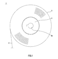
- FIG. 1 is a side view showing a reel member to which the present invention is applied.
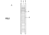
- FIG. 2 is a cross-sectional view showing a reel member to which the present invention is applied.
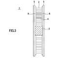
- FIG. 3 is a cross-sectional view showing a reel member in which a rib is provided on the reel flange 5.
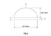
- FIG. 4 is a cross-sectional view showing one shape of the rib.
- FIG. 5 is a cross-sectional view showing one shape of the rib.
- FIG. 6 is a plan view showing one shape of the rib.
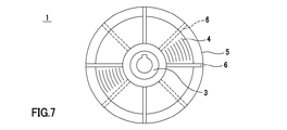
- FIG. 7 is a plan view showing one shape of the rib.
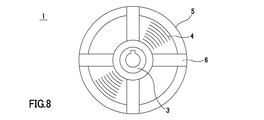
- FIG. 8 is a plan view showing one shape of the rib.
- FIG. 9A is a cross-sectional view showing a reel member formed by fitting a core having a large and small core
- FIG. 9B is an exploded perspective view
- FIG. 10 is a cross-sectional view showing a state where a gap is provided in a reel member in which a rib is provided on the reel flange.
- FIG. 11A is a perspective view showing a diameter-enlarged state of a winding core constituted by an air shaft
- FIG. 11B is a perspective view showing a state where the diameter is reduced.
- FIG. 12 is a cross-sectional view showing a state where a gap is provided in a reel member in which no rib is provided on the reel flange.
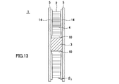
- FIG. 13 is a cross-sectional view showing a reel member in which a taper-shaped rib is provided on the reel flange.
- FIG. 14 is a cross-sectional view showing a state where the reel flange is inclined in a reel member in which a rib is provided on the reel flange.
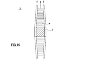
- FIG. 15 is a cross-sectional view illustrating a state where the reel flange is inclined in a reel member in which the rib is not provided on the reel flange.
- FIG. 16 is a front view showing a state in which the adhesive film is passed between the leave flanges while being tilted by the guide roller.
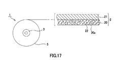
- FIG. 17 is a cross-sectional view showing the configuration of the adhesive film.
- FIG. 18 is a perspective view showing a conventional reel member.
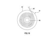
- FIG. 19 is a side view showing a state in which winding deviation or loosening occurs in a conventional reel member.
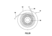
- FIG. 20 is a side view showing a state in which winding of the conventional
- a reel member 1 to which the present invention is applied includes a core 3 around which a tape-like adhesive film 2 is wound, and reel flanges 5 provided on both sides of the core 3.
- the adhesive film 2 wound around the reel member 1 forms a film winding body 4 wound around the core 3.
- the winding core 3 has a cylindrical shape and has substantially the same width as the adhesive film 2 described later. Further, the core 3 is formed with an insertion port 3a through which a rotating device (not shown) for rotating the reel member 1 is inserted at the center. The winding core 3 is engaged with a pair of reel flanges 5 on both sides and rotated integrally with the reel flange 5.
- the pair of reel flanges 5 sandwich the adhesive film 2 wound around the core 3, and are formed in a disk shape using a transparent plastic material, for example. Further, the reel flange 5 may be subjected to electrostatic treatment on the surface in contact with the adhesive film 2. Examples of the method for applying electrostatic treatment include a method of applying a compound such as polythiophene.
- the reel member 1 can prevent blocking of the adhesive film 2 from sticking out of the binder resin, or the sticking out binder resin to the reel flange 5 and preventing the adhesive film 2 from being normally unwound.
- the reel member 1 holds the film winding body 4 between the pair of reel flanges 5 so that the adhesive film 2 is forcibly pulled while the rotation of the core 3 and the reel flange 5 is restricted.
- pulling out of the adhesive film 2 can be suppressed, and the occurrence of winding tightening and the accumulation of winding pressure can be prevented. Therefore, according to the reel member 1, for example, when the adhesive film 2 is pulled around the roller of the transport device, even when the adhesive film 2 is pulled while the rotation of the reel member 1 is locked, the adhesive film 2 can be easily It is possible to prevent the binder resin from protruding and blocking due to winding tightening.
- the reel member 1 can hold the adhesive film 2 by the reel flange 5 by making the distance between the pair of reel flanges 5 the same as the width of the adhesive film 2.
- the reel member 1 has a plurality of ribs 6 formed radially from the inner peripheral side to the outer peripheral side on the inner surface facing the film winding body 4, and the film winding is performed by the ribs 6.
- the body 4 may be clamped.
- the distance between the ribs 6 provided opposite to the pair of reel flanges 5 is the same as the width of the adhesive film 2, whereby the adhesive film 2 is formed by the ribs 6 of the reel flange 5.
- the film winding body 4 can be held.
- the reel member 1 sandwiches the film winding body 4 by the rib 6, thereby reducing the contact area with the film winding body 4 compared to the case where the film winding body 4 is sandwiched across the entire surface of the reel flange 5. Thus, blocking due to contact with the binder resin protruding from the adhesive film 2 can be suppressed.
- the rib 6 may be formed in a substantially semicircular cross section as shown in FIG. 4, and the cross section may be formed in a substantially rectangular shape as shown in FIG. 5.
- the rib 6 can be formed with a size of, for example, a width of 0.5 mm to 5.0 mm and a height of 0.03 mm to 2.0 mm.
- the rib 6 may have a shape that curves from the inner peripheral side to the outer peripheral side of the reel flange 5. In this case, since the reel member 1 has a large contact area between the film winding body 4 and the rib 6, the number of ribs 6 can be reduced.
- the ribs 6 may be alternately provided between the pair of reel flanges 5 at predetermined intervals.
- the load on the film winding body 4 is small and the shape stability of the adhesive film 2 is excellent.
- the rib 6 may be formed in a wide rectangular plate shape as shown in FIG. In this case, since the film winding body 4 is widely supported by the ribs 6 by being in contact with the wide ribs 6, the number of the ribs 6 is reduced and the contact between the ribs 6 and the film winding body 4 is reduced. The area can be maintained.
- the rib 6 is formed from the inner periphery to the outer periphery of the reel flange 5, so that the winding pressure accumulated in the film winding body 4 and the internal stress generated in the reel flange 5 itself are changed due to a change with time. By manifesting, it is possible to prevent the reel flange 5 from being distorted. Therefore, it is possible to prevent the adhesive film 2 from falling off due to the gap between the pair of reel flanges 5 being opened.
- the tolerance of the gap error between the pair of reel flanges 5 is also low. Further, as the adhesive film 2 becomes longer, the diameter of the reel flange 5 becomes larger, and it is difficult to maintain a dimensional tolerance over the entire surface. Therefore, the reel flange 5 is formed with ribs 6 having a small dimensional tolerance from the inner periphery to the outer rim, thereby absorbing the dimensional tolerance of the reel flange 5 and separating the pair of reel flanges due to the distortion of the reel flange 5. It is possible to prevent the adhesive film 2 from dropping off from the film winding body 4 (see FIG. 20), and to make the adhesive film 2 longer and narrower.
- the reel member 1 has a pair of reel flanges 5 engaged with the core 3 so as to be close to and away from each other, so that the distance between the reel flanges 5 and the distance between the ribs 6 according to the width of the adhesive film 2.
- the distance can be adjusted.
- an engagement shaft that is inserted into an engagement port such as the insertion port 3 a provided in the core 3 is erected on the inner peripheral surface of the reel flange 5, and the reel flange 5 depends on the insertion depth of the engagement shaft.
- the structure which adjusts the distance between can be illustrated.
- the reel member 1 includes a winding core 3 that includes a small-diameter core 8 and a large-diameter core 9 that is fitted to the small-diameter core 8 and on which the adhesive film 2 is wound. Also good.
- the small-diameter core 8 is formed with an insertion port 8a through which a rotating device (not shown) that rotates the reel member 1 is inserted.
- the large diameter core 9 is detachably fitted from the small diameter core 8.
- the adhesive film 2 is wound around the large-diameter core 9 in a state where the diameter is expanded by fitting the small-diameter core 8 and the large-diameter core 9 together.
- the core 3 is reduced in diameter by removing the large diameter core 9 from the small diameter core 8 as shown in FIG. 9B.
- the reel member 1 is provided with a gap 10 between the film winding body 4 and the small-diameter core 8. This gap 10 is an area for absorbing the winding pressure accumulated on the inner peripheral side of the wound body when the film winding body 4 is tightened.
- the reel member 1 suppresses the accumulation of the winding pressure by releasing the winding pressure by the adhesive film 2 on the inner circumferential side of the wound body when the winding pressure is transmitted to the inner circumferential side. And the protrusion and blocking of the adhesive film 2 can be prevented.
- the reel member 1 is composed of an air shaft 11 having a variable outer diameter as shown in FIG. Also good.
- the adhesive film 2 is wound around the core 3 in a state in which the lug 12 protrudes and the diameter is increased. Then, when the winding of the adhesive film 2 is completed, the lug 12 is retracted into the shaft and the diameter of the core 3 is reduced, as shown in FIG. 11B. Also by this, as shown in FIG. 10, the reel member 1 is provided with a gap 10 between the film winding body 4 and the air shaft 11.
- the reel member 1 holds the film winding body 4 between the pair of reel flanges 5, after the winding of the adhesive film 2 is finished, the large-diameter core 9 is removed, or Even when the diameter of the core 3 is reduced by retracting the lug 12, the wound state can be maintained without the film winding body 4 being separated.
- the core 3 may be reduced in diameter to provide the gap 10.
- the reel member 1 may be strongly clamped from the inner peripheral side to the outer peripheral side of the film winding body 4 by a pair of reel flanges. Thereby, the reel member 1 prevents the winding pressure from accumulating from the outer peripheral side of the film winding body 4 to the inner peripheral side, and the winding on the inner peripheral side of the film winding body 4 that is likely to protrude or block. Tightening can be suppressed.
- the reel member 1 can be easily pulled out even when the adhesive film 2 is forcibly pulled while the rotation of the reel member 1 is locked and the rotation of the core 3 and the reel flange 5 is restricted. It is not possible to prevent the binder resin from protruding or blocking due to winding tightening.
- the reel member 1 is difficult to be clamped at a uniform pressure between the inner peripheral side and the outer peripheral side of the film wound body 4 by increasing the diameter of the reel flange 5 as the adhesive film 2 becomes longer.
- the shortage of the clamping pressure on the outer peripheral side can be eliminated by configuring the film winding body 4 to be strongly clamped from the inner peripheral side to the outer peripheral side.
- the reel flange 5 has a height from the inner peripheral side to the outer peripheral side, as shown in FIG. 13. It can be formed by providing a tapered rib 14 that increases.
- the gap 10 is provided between the winding core 3 and the film winding body 4 by reducing the diameter of the winding core 3.
- the angle ⁇ 1 of the tapered rib 14 is set, for example, in the range of 0.1 ° to 5 °, preferably 0.3 °.
- the reel member 1 may be configured such that the outer peripheral side of the pair of reel flanges 5 is narrowed by bending or bending the outer peripheral side of the reel flange 5.
- the reel flange 5 may form a rib 6, and the outer periphery side of the film winding body 4 may be strongly clamped by the rib 6, and the rib 6 is not provided as shown in FIG.
- the outer peripheral side of the film winding body 4 may be strongly held by the outer peripheral side inner surface.
- the inclination angle ⁇ 2 of the reel flange 5 is set in a range of 0.2 ° to 5 °, for example.
- the inclination angle ⁇ 3 of the guide roller 15 is set in the range of 0.1 ° to 15 °, for example.
- the adhesive film 2 that has passed between the pair of reel flanges 5 is wound in parallel with the outer peripheral surface of the core 3 to form a film wound body 4, and the inner peripheral surface of the pair of reel flanges 5 or the ribs 6, 14 will be held. Thereby, the adhesive film 2 can be smoothly wound around the reel member 1.
- the adhesive film 2 is passed between the pair of reel flanges 5 while being guided by the guide roller 15 so as to be inclined with respect to the outer periphery of the core 3. Thereby, the adhesive film 2 can be smoothly unwound from the reel member 1 without slidingly contacting the reel flange 5.
- the unwound adhesive film 2 forms the film winding body 4 and is sandwiched between the inner peripheral surfaces of the pair of reel flanges 5 or the ribs 6 and 14, and thus is applied at the time of unwinding. It is possible to prevent the load from being transmitted to the film winding body 4 as a winding pressure, and to prevent the binder resin from protruding or blocking due to winding tightening.
- the adhesive film 2 wound around the reel member 1 will be described.
- the adhesive film 2 includes an adhesive layer 20 and a base film 21 serving as a support that supports the adhesive layer 20.
- the adhesive layer 20 can be an anisotropic conductive film (ACF: Anisotropic Conductive Film) containing conductive particles 22 in a binder (insulating adhesive composition) 20a, but is not limited thereto.
- ACF Anisotropic Conductive Film
- NCF Non-Conductive Film
- the binder 20a of the adhesive film for example, a normal binder containing a film forming resin, a thermosetting resin, a latent curing agent, a silane coupling agent, or the like can be used.
- a normal binder containing a film forming resin, a thermosetting resin, a latent curing agent, a silane coupling agent, or the like can be used.
- an anisotropic conductive composition in which the conductive particles 22 are dispersed in the binder 20 a or an insulating adhesive composition that does not contain the conductive particles 22 in the binder 20 a is applied on the base film 21.
- the film is formed on the base film 21.
- the base film 21 supports the binder 20a in the form of a film.
- PET Poly Ethylene Terephthalate
- OPP Oriented Polypropylene
- PMP Poly-4-methlpentene-1
- PTFE Polytetrafluoroethylene
- the film-forming resin contained in the binder 20a is preferably a resin having an average molecular weight of about 10,000 to 80,000.
- the film forming resin include various resins such as an epoxy resin, a modified epoxy resin, a urethane resin, and a phenoxy resin. Among these, phenoxy resin is particularly preferable from the viewpoint of film formation state, connection reliability, and the like.
- thermosetting resin is not particularly limited as long as it has fluidity at room temperature, and examples thereof include commercially available epoxy resins and acrylic resins.
- the epoxy resin is not particularly limited.
- naphthalene type epoxy resin biphenyl type epoxy resin, phenol novolac type epoxy resin, bisphenol type epoxy resin, stilbene type epoxy resin, triphenolmethane type epoxy resin, phenol aralkyl type epoxy resin.
- an acrylic compound, liquid acrylate, etc. can be selected suitably.
- what made acrylate the methacrylate can also be selected from methyl acrylate, ethyl acrylate, isopropy
- the latent curing agent is not particularly limited, and examples thereof include various curing agents such as a heat curing type and a UV curing type.
- the latent curing agent does not normally react, but is activated by various triggers selected according to applications such as heat, light, and pressure, and starts the reaction.
- the activation method of the thermally activated latent curing agent includes a method of generating active species (cations and anions) by a dissociation reaction by heating, and the like.
- Thermally active latent curing agents include imidazole series, hydrazide series, boron trifluoride-amine complex, sulfonium salt, amine imide, polyamine salt, dicyandiamide, and modified products thereof. The above mixture may be sufficient. Among these, a microcapsule type imidazole-based latent curing agent is preferable.
- the silane coupling agent is not particularly limited, and examples thereof include an epoxy type, an amino type, a mercapto sulfide type, and a ureido type. By adding the silane coupling agent, the adhesion at the interface between the organic material and the inorganic material is improved.
- Examples of the conductive particles 22 include any known conductive particles used in anisotropic conductive films.
- Examples of the conductive particles 22 include particles of various metals and metal alloys such as nickel, iron, copper, aluminum, tin, lead, chromium, cobalt, silver, gold, metal oxide, carbon, graphite, glass, ceramic, Examples thereof include those in which the surface of particles such as plastic is coated with metal, or those in which the surface of these particles is further coated with an insulating thin film.
- examples of the resin particle include an epoxy resin, a phenol resin, an acrylic resin, an acrylonitrile / styrene (AS) resin, a benzoguanamine resin, a divinylbenzene resin, a styrene resin, and the like. Can be mentioned.
- the adhesive film 2 in which the adhesive film 2 made of ACF or NCF is laminated on the base film 21 is used.
- the present invention is not limited to this example.
- the film laminate may be an anisotropic conductive film having two or more layers in which ACF and NCF are laminated.
- the adhesive film 2 may have a configuration in which a cover film is provided on the surface opposite to the surface on which the base film 21 of the adhesive film 2 is laminated.
- a cover film is provided on the surface opposite to the surface on which the base film 21 of the adhesive film 2 is laminated.
- it is good also as an adhesive film with copper foil for electrically connecting the electrodes of a plurality of photovoltaic cells.
- a reel member that sandwiches the wound body of the adhesive film with a pair of reel flanges and a conventional reel member are prepared, the adhesive film is pulled out, and the length of the adhesive film is extended or blocked. The occurrence was observed.
- Example 1 a reel member in which 12 linear ribs are radially formed on the inner surface facing the film winding body from the inner peripheral side to the outer peripheral side, and the film winding body is sandwiched by the ribs. was used (see FIG. 3).
- the outer diameter of the reel flange is 250 mm.
- Example 2 the same conditions as in Example 1 were used except that a winding core composed of a large-diameter core and a small-diameter core was used and a reel member in which a gap was formed between the film winding body and the winding core was used. (See FIG. 10).
- Example 3 12 taper-shaped ribs were radially formed on the inner surface facing the film winding body from the inner peripheral side toward the outer peripheral side, and the film winding body was sandwiched by the tapered ribs.
- a reel member was used (see FIG. 13).
- the outer diameter of the reel flange is 300 mm.
- the taper angle of the tapered rib is 0.3 °.
- the core which consists of a large diameter core and a small diameter core was used, and the space
- Comparative Example 1 a conventional reel member having a clearance between the film winding body and the reel flange was used (see FIG. 18).
- the reel members according to Examples and Comparative Examples were each wound with an adhesive film of 300 m, 500 m, 600 m, and 700 m, and observed for protrusion and blocking. ⁇ when no protrusion or blocking is observed, and when protrusion is recognized but blocking is not recognized, it is ⁇ as no problem in practical use, and when protrusion and blocking are recognized, it is assumed that it cannot be put into practical use. It was. The results are shown in Table 1.
- Example 2 when looking at Examples 1 to 3, the protrusion in Example 2 with a gap was suppressed more than in Example 1 when the length was increased. From this, it can be seen that the formation of voids is advantageous for suppressing the cumulative winding pressure. Further, the protrusion of Example 3 in which the tapered rib was formed was suppressed from being extended when the length was increased. From this, it can be seen that it is advantageous for the accumulation suppression of the winding pressure that the film winding body is strongly held from the inner peripheral side to the outer peripheral side.
Landscapes
- Storage Of Web-Like Or Filamentary Materials (AREA)
Abstract
接着フィルムの長尺化と共に、巻圧によるはみ出しやブロッキングを抑制する。リール部材は、テープ状の接着フィルム(2)が巻回される巻芯(3)と、巻芯(3)の両側に設けられた一対のリールフランジ(5)とを備え、一対のリールフランジ(5)によって接着フィルム(2)の巻装体(4)を挟持する。
Description
本発明は、テープ状の接着フィルムが巻回されるリール部材に関し、特に、接着フィルム巻装体の巻締まりを防止したリール部材、接着フィルムの巻回方法、接着フィルムの巻き出し方法に関する。
本出願は、日本国において2012年4月6日に出願された日本特許出願番号特願2012-87758を基礎として優先権を主張するものであり、この出願を参照することにより、本出願に援用される。
本出願は、日本国において2012年4月6日に出願された日本特許出願番号特願2012-87758を基礎として優先権を主張するものであり、この出願を参照することにより、本出願に援用される。
従来から、基板に接着フィルムを用いて電子部品を実装する実装法が用いられている。例えば、液晶表示パネル(LCDパネル)の周縁部に導電性の接着フィルムを介して液晶駆動回路であるICチップを実装するCOG(Chip on Glass)実装法や、太陽電池セルにインターコネクタとなるタブ線を接続する接続法が挙げられる。
導電性の接着フィルムは、バインダー樹脂に導電性粒子が分散された接着剤層が、支持体となるベースフィルム上に形成されたものである。このような導電性接着フィルム50は、例えば、図18に示すように、一対のリールフランジ52を有するリール部材51の巻芯53に巻回されたフィルム巻装体の形状で使用される(例えば、特許文献1を参照)。
ところで、導電性接着フィルム50のリール交換を行うためには一端ラインを停止し、接着フィルムを搬送ローラに引き回す等繁雑な作業を要し、COG実装等の工程において大きなタイムロスとなっている。このため、導電性接着フィルム50のリール交換作業の簡素化や交換回数の低減のための方策が種々試みられている。なかでも、導電性接着フィルム50の長尺化がリール交換の回数低減に効果的である。
しかし、リール部材51の巻芯53に導電性接着フィルム50が長尺に巻回されることで、巻芯53付近に巻圧が累積して巻締まりが起こる。これにより、フィルム巻装体は、バインダー樹脂がベースフィルムの両側からはみ出し、実使用時に接着性や導通信頼性を損なうおそれがある。また、はみ出したバインダー樹脂がリールフランジ52に付着して導電性接着フィルム50を正常に巻き出せなくなるいわゆるブロッキングという現象が発生するおそれがある。この減少は、特に、常温においてバインダー樹脂の粘性が低い導電性接着フィルムにおいて、顕著にみられる傾向があった。
このような不具合に対して、ベースフィルムを接着剤層よりも幅広に設けることではみ出しを抑制する方法(特許文献2、3を参照)や、接着フィルムを巻き取る張力を巻芯部側よりも外周側で弱くすることで巻芯部に巻圧が集中することを防止する方法(いわゆるテーパーテンション)も提案されている。
しかし、ベースフィルムを接着剤層よりも幅広にする方法では、製造が煩雑であることに加え、はみ出しやブロッキングを抑制することはできても、接着剤層が巻圧によって流動することは防止できず、実使用時において接着性や導通信頼性を損なうおそれは依然として残る。
また、テーパーテンションをかけると、図19に示すように、巻芯の外周側で張力不足による巻ズレや巻緩みが発生し、また、図20に点線で示すように、導電性接着フィルム50のリールフランジ52と巻装体との間への脱落などが起きやすくなるなど、別の問題が生じる。
そこで、本発明は、接着フィルムの長尺化を図ると共に、巻圧集中によるはみ出しやブロッキングを抑制し、かつ巻ズレ等も防止することができるリール部材、接着フィルムの巻回方法、接着フィルムの巻き出し方法を提供することを目的とする。
上述した課題を解決するために、本発明に係るリール部材は、テープ状の接着フィルムが巻回される巻芯と、上記巻芯の両側に設けられた一対のリールフランジとを備え、上記一対のリールフランジによって上記接着フィルムの巻装体を挟持するものである。
本発明に係る接着フィルムの巻回方法は、テープ状の接着フィルムが巻回される巻芯と、上記巻芯の両側に設けられた一対のリールフランジとを備え、上記一対のリールフランジによって上記接着フィルムの巻装体を挟持するリール部材への上記接着フィルムの巻回方法において、上記接着フィルムを上記巻芯の外周面に対して傾けるようにガイドしながら上記一対のリールフランジ間を通すものである。
本発明に係る接着フィルムの巻き出し方法は、テープ状の接着フィルムが巻回された巻芯と、上記巻芯の両側に設けられた一対のリールフランジとを備え、上記一対のリールフランジによって上記接着フィルムの巻装体を挟持するリール部材から上記接着フィルムを巻き出す巻き出し方法において、上記接着フィルムを上記巻芯の外周面に対して傾けるようにガイドしながら上記一対のリールフランジ間を通すものである。
本発明によれば、リール部材は、巻芯にテープ状の接着フィルムが巻回されるとともに、一対のリールフランジによって接着フィルム2巻装体を挟持する。これにより、リール部材は、フィルム巻装体に巻締まりが生じて巻芯付近に巻圧が累積することを防止することができる。
以下、本発明が適用されたリール部材、接着フィルムの巻回方法、接着フィルムの巻き出し方法について、図面を参照しながら詳細に説明する。なお、本発明は、以下の実施形態のみに限定されるものではなく、本発明の要旨を逸脱しない範囲内において種々の変更が可能であることは勿論である。また、図面は模式的なものであり、各寸法の比率等は現実のものとは異なることがある。具体的な寸法等は以下の説明を参酌して判断すべきものである。また、図面相互間においても互いの寸法の関係や比率が異なる部分が含まれていることは勿論である。
本発明が適用されたリール部材1は、図1に示すように、テープ状の接着フィルム2が巻回される巻芯3と、巻芯3の両側に設けられたリールフランジ5とを備える。リール部材1に巻回された接着フィルム2は、巻芯3に巻回されたフィルム巻装体4を形成する。
[巻芯/リールフランジ]
巻芯3は、円筒形状をなし、後述する接着フィルム2と略同じ幅を有する。また、巻芯3は、中心部にリール部材1を回転駆動する図示しない回転装置が挿通する挿通口3aが形成されている。そして、巻芯3は、両側は一対のリールフランジ5が係合され、リールフランジ5と一体に回転される。
巻芯3は、円筒形状をなし、後述する接着フィルム2と略同じ幅を有する。また、巻芯3は、中心部にリール部材1を回転駆動する図示しない回転装置が挿通する挿通口3aが形成されている。そして、巻芯3は、両側は一対のリールフランジ5が係合され、リールフランジ5と一体に回転される。
一対のリールフランジ5は、巻芯3に巻回された接着フィルム2を挟持するものであり、例えば透明なプラスチック材料を用いて円盤状に形成されている。また、リールフランジ5は、接着フィルム2と接する面に、静電処理を施すようにしてもよい。静電処理を施す方法としては、例えば、ポリチオフェン等の化合物を塗布する方法が挙げられる。
[フィルム巻装体を挟持]
リール部材1は、巻芯3にテープ状の接着フィルム2が巻回されるとともに、図2に示すように、一対のリールフランジ5によって接着フィルム2の巻装体4を挟持する。これにより、リール部材1は、フィルム巻装体4に巻締まりが生じて巻芯3付近に巻圧が累積することを防止することができる。
リール部材1は、巻芯3にテープ状の接着フィルム2が巻回されるとともに、図2に示すように、一対のリールフランジ5によって接着フィルム2の巻装体4を挟持する。これにより、リール部材1は、フィルム巻装体4に巻締まりが生じて巻芯3付近に巻圧が累積することを防止することができる。
すなわち、リール部材1のフィルム巻装体4は、リールフランジ5に挟持されることで、巻圧の内周側への伝達を抑制し、巻締まりの発生及び内周側への巻圧の累積を防止することができる。したがって、リール部材1は、接着フィルム2のバインダー樹脂のはみ出しや、はみ出したバインダー樹脂がリールフランジ5に付着して正常に接着フィルム2が巻き出せなくなるブロッキングを防止することができる。
また、リール部材1は、一対のリールフランジ5によってフィルム巻装体4を挟持することにより、巻芯3やリールフランジ5の回転が規制された状態で接着フィルム2が強引に引っ張られた場合にも、接着フィルム2の引き出しを抑制し、巻締まりの発生及び巻圧の累積を防止することができる。したがって、リール部材1によれば、例えば接着フィルム2を搬送装置のローラに引き回す際に、リール部材1の回転がロックされた状態で接着フィルム2が引っ張られた場合にも、接着フィルム2を容易に引き出すことができず、巻締まりによるバインダー樹脂のはみ出しやブロッキングの発生を防止することができる。
リール部材1は、図2に示すように、一対のリールフランジ5の間隔を接着フィルム2の幅と同距離にすることで、リールフランジ5によって接着フィルム2を挟持することができる。
[リブ]
また、リール部材1は、図3に示すように、フィルム巻装体4と対峙する内面に、内周側から外周側に向かって複数のリブ6を放射状に形成し、当該リブ6によってフィルム巻装体4を挟持してもよい。このとき、リール部材1は、一対のリールフランジ5に相対向して設けられたリブ6の間隔を、接着フィルム2の幅と同距離にすることで、リールフランジ5のリブ6によって接着フィルム2のフィルム巻装体4を挟持することができる。
また、リール部材1は、図3に示すように、フィルム巻装体4と対峙する内面に、内周側から外周側に向かって複数のリブ6を放射状に形成し、当該リブ6によってフィルム巻装体4を挟持してもよい。このとき、リール部材1は、一対のリールフランジ5に相対向して設けられたリブ6の間隔を、接着フィルム2の幅と同距離にすることで、リールフランジ5のリブ6によって接着フィルム2のフィルム巻装体4を挟持することができる。
リール部材1は、リブ6によってフィルム巻装体4を挟持することで、リールフランジ5の全面でフィルム巻装体4を挟持する場合に比してフィルム巻装体4との接触面積を低減させ、これにより接着フィルム2よりはみ出したバインダー樹脂との接触によるブロッキングの発生を抑制することができる。
なお、リブ6は、図4に示すように、断面略半円状に形成してもよく、また、図5に示すように、断面が略矩形状に形成されてもよい。また、リブ6は、例えば、幅0.5mm~5.0mm、高さ0.03mm~2.0mmのサイズで形成することができる。
また、リブ6は、図6に示すように、リールフランジ5の内周側から外周側にかけて湾曲する形状であってもよい。この場合、リール部材1は、フィルム巻装体4とリブ6との接触面積が大きいため、リブ6の本数を減らすことができる。
また、リブ6は、図7に示すように、一対のリールフランジ5の間で所定間隔毎に交互に設けるようにしてもよい。この場合、リール部材1は、リブ6とフィルム巻装体4とが交互に接触するため、フィルム巻装体4への負荷が少なく、接着フィルム2の形状安定性に優れる。
さらに、リブ6は、図8に示すように、幅広の矩形板状に形成してもよい。この場合、幅広のリブ6に当接されることで、フィルム巻装体4はリブ6によって広汎に支持されるため、リブ6の本数を減らすとともに、リブ6とフィルム巻装体4との接触面積は維持することができる。
なお、リール部材1は、リブ6をリールフランジ5の内周から外周縁にかけて形成することで、フィルム巻装体4に累積した巻圧や、リールフランジ5そのものに生じる内部応力が径時変化によって発現することにより、リールフランジ5に歪みが生じることを抑制することができる。したがって、一対のリールフランジ5の間隔が開くことによる接着フィルム2の脱落を防止することができる。
近年は、電子部品の微細化や接着領域の狭小化に伴い、接着フィルム2の幅も細くなってきているため、一対のリールフランジ5の間隔誤差も許容度が低くなっている。また、接着フィルム2の長尺化に伴い、リールフランジ5の径も大きくなり、全面に亘って寸法公差を維持することが厳しくなっている。そこで、リールフランジ5は、寸法公差の少ないリブ6を内周から外周縁にかけて形成することで、リールフランジ5の寸法公差を吸収し、リールフランジ5の歪みによる一対のリールフランジの離間や、これによる接着フィルム2のフィルム巻装体4からの脱落(図20参照)を防止し、接着フィルム2の長尺化、細幅化を図ることができる。
また、リール部材1は、巻芯3に対して一対のリールフランジ5が互いに近接離間可能に係合することにより、接着フィルム2の幅に応じてリールフランジ5間の距離や、リブ6間の距離を調整することができる。かかる構成は、例えば、巻芯3に設けた挿通口3a等の係合口に挿通する係合軸をリールフランジ5の内周面に立設し、当該係合軸の挿通深さによってリールフランジ5間の距離を調整する構成が例示できる。
[巻芯2重コア]
また、図9Aに示すように、リール部材1は、巻芯3を、小径コア8と、小径コア8に嵌合されるとともに接着フィルム2が巻回される大径コア9とから構成してもよい。小径コア8には、中心部にリール部材1を回転駆動する図示しない回転装置が挿通する挿通口8aが形成されている。大径コア9は、小径コア8から着脱可能に嵌合されている。
また、図9Aに示すように、リール部材1は、巻芯3を、小径コア8と、小径コア8に嵌合されるとともに接着フィルム2が巻回される大径コア9とから構成してもよい。小径コア8には、中心部にリール部材1を回転駆動する図示しない回転装置が挿通する挿通口8aが形成されている。大径コア9は、小径コア8から着脱可能に嵌合されている。
このような巻芯3は、小径コア8と大径コア9とが嵌合されることで拡径された状態で、大径コア9に接着フィルム2が巻回される。そして、巻芯3は、接着フィルム2の巻回が終了すると、図9Bに示すように、大径コア9が小径コア8から取り外されることにより縮径される。これにより、図10に示すように、リール部材1は、フィルム巻装体4と小径コア8との間に空隙10が設けられる。この空隙10は、フィルム巻装体4に巻締まりが発生した際に、巻装体の内周側に累積する巻圧を吸収するための領域である。空隙10が設けられることにより、リール部材1は、巻圧が内周側に伝達されると、巻装体内周側の接着フィルム2によって巻圧が解放されることで、巻圧の累積を抑制し、接着フィルム2のはみ出しやブロッキングを防止することができる。
[エアシャフト]
また、リール部材1は、巻芯3を大小のコア8,9から構成する他にも、図11に示すように、巻芯3を、外径が可変とされたエアシャフト11で構成してもよい。この場合、巻芯3は、図11Aに示すように、ラグ12を突出させて拡径された状態で接着フィルム2が巻回される。そして、巻芯3は、接着フィルム2の巻回が終了すると、図11Bに示すように、ラグ12がシャフト内部に後退し縮径する。これによっても、図10に示すように、リール部材1は、フィルム巻装体4とエアシャフト11との間に空隙10が設けられる。
また、リール部材1は、巻芯3を大小のコア8,9から構成する他にも、図11に示すように、巻芯3を、外径が可変とされたエアシャフト11で構成してもよい。この場合、巻芯3は、図11Aに示すように、ラグ12を突出させて拡径された状態で接着フィルム2が巻回される。そして、巻芯3は、接着フィルム2の巻回が終了すると、図11Bに示すように、ラグ12がシャフト内部に後退し縮径する。これによっても、図10に示すように、リール部材1は、フィルム巻装体4とエアシャフト11との間に空隙10が設けられる。
ここで、上述したように、リール部材1は、一対のリールフランジ5でフィルム巻装体4を挟持しているため、接着フィルム2の巻回が終了した後に、大径コア9を取り外し、あるいはラグ12を後退させることにより巻芯3を縮径させても、フィルム巻装体4がばらけることなく巻回状態を維持することができる。
また、図12に示すように、リールフランジ5にリブ6が形成されていないリール部材1においても、巻芯3を縮径させて空隙10を設けてもよい。
[フィルム巻装体の内周側から外周側にかけて強く挟持]
また、リール部材1は、一対のリールフランジによって、フィルム巻装体4の内周側から外周側にかけて強く挟持していくようにしてもよい。これにより、リール部材1は、フィルム巻装体4の外周側から巻圧が内周側へ累積していくことを防止し、はみ出しやブロッキングが生じやすいフィルム巻装体4の内周側の巻締まりを抑制することができる。
また、リール部材1は、一対のリールフランジによって、フィルム巻装体4の内周側から外周側にかけて強く挟持していくようにしてもよい。これにより、リール部材1は、フィルム巻装体4の外周側から巻圧が内周側へ累積していくことを防止し、はみ出しやブロッキングが生じやすいフィルム巻装体4の内周側の巻締まりを抑制することができる。
また、リール部材1は、リール部材1の回転がロックされ巻芯3やリールフランジ5の回転が規制された状態で接着フィルム2が強引に引っ張られた場合にも、接着フィルム2を容易に引き出すことができず、巻締まりによるバインダー樹脂のはみ出しやブロッキングの発生を防止することができる。
さらに、リール部材1は、接着フィルム2の長尺化に伴いリールフランジ5が大径化することで、フィルム巻装体4の内周側と外周側とで均一な圧力で挟持することが困難となるが、フィルム巻装体4の内周側から外周側にかけて強く挟持するように構成することで、外周側における挟持圧力の不足を解消することができる。
一対のリールフランジによって、フィルム巻装体4の内周側から外周側にかけて強く挟持していく構成としては、例えば図13に示すように、リールフランジ5に、内周側から外周側にかけて高さが増大するテーパ状のリブ14を設けることにより形成することができる。なお、図13では、巻芯3を縮径することによりフィルム巻装体4との間に空隙10を設けている。また、テーパ状リブ14の角度θ1は、例えば0.1°~5°の範囲で設定され、好ましくは0.3°に設定される。
また、リール部材1は、図14に示すように、リールフランジ5の外周側を屈曲あるいは湾曲させることで、一対のリールフランジ5の外周側の間隔を狭めるようにしてもよい。このとき、リールフランジ5は、リブ6を形成し、リブ6によってフィルム巻装体4の外周側を強く挟持してもよく、図15に示すように、リブ6を設けず、リールフランジ5の外周側内面によってフィルム巻装体4の外周側を強く挟持してもよい。また、リールフランジ5の傾斜角度θ2は、例えば0.2°~5°の範囲で設定される。
[接着フィルムの巻回方法]
次いで、リール部材1へ接着フィルム2を巻回する工程について説明する。リール部材1は、一対のリールフランジ5によってフィルム巻装体4を挟持するため、一対のリールフランジ5の間隔がほぼ接着フィルム2の幅と同じとされている。そのため、リール部材1は、接着フィルム2を巻芯3に巻回させる際には、図16に示すように、接着フィルム2を巻芯3の外周に対して傾けるようにガイドしながら一対のリールフランジ5間を通す。
次いで、リール部材1へ接着フィルム2を巻回する工程について説明する。リール部材1は、一対のリールフランジ5によってフィルム巻装体4を挟持するため、一対のリールフランジ5の間隔がほぼ接着フィルム2の幅と同じとされている。そのため、リール部材1は、接着フィルム2を巻芯3に巻回させる際には、図16に示すように、接着フィルム2を巻芯3の外周に対して傾けるようにガイドしながら一対のリールフランジ5間を通す。
すなわち、リール部材1に対して、従来通り巻芯3の外周面と平行に接着フィルム2を通したのでは、接着フィルム2の両側が一対のリールフランジ5の内周面と摺接して、巻芯3への巻回が阻害されてしまう。そこで、リール部材1へ接着フィルム2を巻回する際には、接着フィルム2をガイドローラ15によって、一対のリールフランジ5と摺接しない角度まで巻芯3の外周面に対して傾ける。ガイドローラ15の傾斜角度θ3は、例えば0.1°~15°の範囲で設定される。
一対のリールフランジ5間を通った接着フィルム2は、巻芯3の外周面と平行に巻回されてフィルム巻装体4を形成し、一対のリールフランジ5の内周面、あるいはリブ6,14に挟持されていく。これにより、接着フィルム2をリール部材1に対してスムーズに巻回することができる。
[接着フィルムの巻き出し方法]
同様に、リール部材1から接着フィルム2を巻き出す工程においても、接着フィルム2をガイドローラ15によって巻芯3の外周に対して傾けるようにガイドしながら一対のリールフランジ5間を通す。これにより、接着フィルム2は、リールフランジ5に摺接することなく、リール部材1からスムーズに巻き出されることができる。
同様に、リール部材1から接着フィルム2を巻き出す工程においても、接着フィルム2をガイドローラ15によって巻芯3の外周に対して傾けるようにガイドしながら一対のリールフランジ5間を通す。これにより、接着フィルム2は、リールフランジ5に摺接することなく、リール部材1からスムーズに巻き出されることができる。
このとき、巻き出されていない接着フィルム2は、フィルム巻装体4を形成し、一対のリールフランジ5の内周面、あるいはリブ6,14に挟持されているため、巻き出しの際に掛かる負荷がフィルム巻装体4に巻圧として伝達することが防止され、巻締まりによるバインダー樹脂のはみ出しやブロッキングを防止することができる。
[接着フィルムの構成]
ここで、リール部材1に巻回される接着フィルム2について説明する。接着フィルム2は、図17に示すように、接着剤層20と接着剤層20を支持する支持体となるベースフィルム21とを備える。
ここで、リール部材1に巻回される接着フィルム2について説明する。接着フィルム2は、図17に示すように、接着剤層20と接着剤層20を支持する支持体となるベースフィルム21とを備える。
接着剤層20は、バインダー(絶縁性接着剤組成物)20aに導電性粒子22を含有する異方性導電フィルム(ACF:Anisotropic Conductive Film)とすることができるが、これに限定されず、バインダー20aに導電性粒子22を含有しない絶縁性接着フィルム(NCF:Non-Conductive Film)であってもよい。
接着フィルム2のバインダー20aは、例えば、膜形成樹脂、熱硬化性樹脂、潜在性硬化剤、シランカップリング剤等を含有する通常のバインダーを用いることができる。接着フィルム2は、バインダー20aに導電性粒子22が分散された異方性導電組成物、又は、バインダー20aに導電性粒子22を含有しない絶縁性接着剤組成物を、ベースフィルム21上に塗布することにより、ベースフィルム21上に形成される。
ベースフィルム21は、バインダー20aをフィルム状に支持するものであり、例えば、PET(Poly Ethylene Terephthalate)、OPP(Oriented Polypropylene)、PMP(Poly-4-methlpentene-1)、PTFE(Polytetrafluoroethylene)等にシリコーン等の剥離剤を塗布することにより形成される。
バインダー20aに含有される膜形成樹脂としては、平均分子量が10000~80000程度の樹脂が好ましい。膜形成樹脂としては、エポキシ樹脂、変形エポキシ樹脂、ウレタン樹脂、フェノキシ樹脂等の各種の樹脂が挙げられる。中でも、膜形成状態、接続信頼性等の観点からフェノキシ樹脂が特に好ましい。
熱硬化性樹脂としては、常温で流動性を有していれば特に限定されず、例えば、市販のエポキシ樹脂、アクリル樹脂等が挙げられる。
エポキシ樹脂としては、特に限定されないが、例えば、ナフタレン型エポキシ樹脂、ビフェニル型エポキシ樹脂、フェノールノボラック型エポキシ樹脂、ビスフェノール型エポキシ樹脂、スチルベン型エポキシ樹脂、トリフェノールメタン型エポキシ樹脂、フェノールアラルキル型エポキシ樹脂、ナフトール型エポキシ樹脂、ジシクロペンタジエン型エポキシ樹脂、トリフェニルメタン型エポキシ樹脂等が挙げられる。これらは単独でも、2種以上の組み合わせであってもよい。
アクリル樹脂としては、特に制限はなく、目的に応じてアクリル化合物、液状アクリレート等を適宜選択することができる。例えば、メチルアクリレート、エチルアクリレート、イソプロピルアクリレート、イソブチルアクリレート、エポキシアクリレート、エチレングリコールジアクリレート、ジエチレングリコールジアクリレート、トリメチロールプロパントリアクリレート、ジメチロールトリシクロデカンジアクリレート、テトラメチレングリコールテトラアクリレート、2-ヒドロキシ-1,3-ジアクリロキシプロパン、2,2-ビス[4-(アクリロキシメトキシ)フェニル]プロパン、2,2-ビス[4-(アクリロキシエトキシ)フェニル]プロパン、ジシクロペンテニルアクリレート、トリシクロデカニルアクリレート、トリス(アクリロキシエチル)イソシアヌレート、ウレタンアクリレート、エポキシアクリレート等を挙げることができる。なお、アクリレートをメタクリレートにしたものを用いることもできる。これらは、1種単独で使用してもよいし、2種以上を併用してもよい。
潜在性硬化剤としては、特に限定されないが、例えば、加熱硬化型、UV硬化型等の各種硬化剤が挙げられる。潜在性硬化剤は、通常では反応せず、熱、光、加圧等の用途に応じて選択される各種のトリガにより活性化し、反応を開始する。熱活性型潜在性硬化剤の活性化方法には、加熱による解離反応などで活性種(カチオンやアニオン)を生成する方法、室温付近ではエポキシ樹脂中に安定に分散しており高温でエポキシ樹脂と相溶・溶解し、硬化反応を開始する方法、モレキュラーシーブ封入タイプの硬化剤を高温で溶出して硬化反応を開始する方法、マイクロカプセルによる溶出・硬化方法等が存在する。熱活性型潜在性硬化剤としては、イミダゾール系、ヒドラジド系、三フッ化ホウ素-アミン錯体、スルホニウム塩、アミンイミド、ポリアミン塩、ジシアンジアミド等や、これらの変性物があり、これらは単独でも、2種以上の混合体であってもよい。中でも、マイクロカプセル型イミダゾール系潜在性硬化剤が好適である。
シランカップリング剤としては、特に限定されないが、例えば、エポキシ系、アミノ系、メルカプト・スルフィド系、ウレイド系等を挙げることができる。シランカップリング剤を添加することにより、有機材料と無機材料との界面における接着性が向上される。
導電性粒子22としては、異方性導電フィルムにおいて使用されている公知の何れの導電性粒子を挙げることができる。導電性粒子22としては、例えば、ニッケル、鉄、銅、アルミニウム、錫、鉛、クロム、コバルト、銀、金等の各種金属や金属合金の粒子、金属酸化物、カーボン、グラファイト、ガラス、セラミック、プラスチック等の粒子の表面に金属をコートしたもの、或いは、これらの粒子の表面に更に絶縁薄膜をコートしたもの等が挙げられる。樹脂粒子の表面に金属をコートしたものである場合、樹脂粒子としては、例えば、エポキシ樹脂、フェノール樹脂、アクリル樹脂、アクリロニトリル・スチレン(AS)樹脂、ベンゾグアナミン樹脂、ジビニルベンゼン系樹脂、スチレン系樹脂等の粒子を挙げることができる。
なお、上述した説明では、ベースフィルム21上にACF又はNCFからなる接着フィルム2が積層されてなる接着フィルム2を用いたが、この例に限定されるものではない。例えば、フィルム積層体は、ACFとNCFとが積層された2層以上の異方性導電フィルムとしてもよい。
また、接着フィルム2は、接着フィルム2のベースフィルム21が積層された面とは反対の面側にもカバーフィルムを設ける構成としてもよい。また、例えば、複数の太陽電池セルの電極同士を電気的に接続するための銅箔付き接着フィルムとしてもよい。
次いで、本発明の実施例について説明する。本実施例では、一対のリールフランジによって接着フィルムの巻装体を挟持しているリール部材と、従来のリール部材とを用意し、接着フィルムを引き出し、接着フィルムの長さ毎にはみ出しやブロッキングの発生について観察した。
実施例1では、フィルム巻装体と対峙する内面に、内周側から外周側に向かって複数の直線状のリブを放射状に12本形成し、当該リブによってフィルム巻装体を挟持したリール部材を用いた(図3参照)。リールフランジの外径は250mmである。
実施例2では、大径コアと小径コアとからなる巻芯を用い、フィルム巻装体と巻芯との間に空隙が形成されたリール部材を用いた他は、実施例1と同一の条件とした(図10参照)。
実施例3では、フィルム巻装体と対峙する内面に、内周側から外周側に向かって複数のテーパ状のリブを放射状に12本形成し、当該テーパ状リブによってフィルム巻装体を挟持したリール部材を用いた(図13参照)。リールフランジの外径は300mmである。テーパ状リブのテーパ角度は、0.3°である。また、実施例3では、大径コアと小径コアとからなる巻芯を用い、フィルム巻装体と巻芯との間に空隙を設けた。
比較例1では、フィルム巻装体とリールフランジとの間にクリアランスを有する従来のリール部材を用いた(図18参照)。
実施例及び比較例に係るリール部材には、それぞれ、接着フィルムを300m、500m、600m、700m巻回し、はみ出し及びブロッキングの有無を観察した。はみ出し及びブロッキングが認められない場合を○、はみ出しは認められるがブロッキングは認められない場合は、実用上問題なしとして△とし、はみ出し及びブロッキングが認められた場合は、実用に耐えられないものとして×とした。結果を表1に示す。

表1に示すように、実施例1~3によれば、700m巻回した状態でも、ブロッキングは認められず、実用に耐えられるものであった。一方、比較例1では、300mまでは問題ないが、500m以上巻回したものでははみ出し及びブロッキングが認められ、実用に耐えられなかった。これより、一対のリールフランジによって接着フィルムの巻装体を挟持することにより、長尺化を図ることができることがわかる。
また、実施例1~3をみると、実施例1よりも空隙を設けた実施例2の方が長尺化に際してはみ出しが抑制された。これより、空隙を形成することが巻圧の累積抑制に有利であることがわかる。また、実施例2よりもテーパ状リブが形成された実施例3の方が長尺化に際してはみ出しが抑制された。これより、フィルム巻装体の内周側から外周側にかけて強く挟持していくことが巻圧の累積抑制に有利であることがわかる。
1 リール部材、2 接着フィルム、3 巻芯、3a 挿通口、4 フィルム巻装体、5 リールフランジ、6 リブ、8 小径コア、9 大径コア、10 空隙、11 エアシャフト、12 ラグ、14 テーパ状リブ、20 接着剤層、21 ベースフィルム、22 導電性粒子
Claims (11)
- テープ状の接着フィルムが巻回される巻芯と、
上記巻芯の両側に設けられた一対のリールフランジとを備え、
上記一対のリールフランジによって上記接着フィルムの巻装体を挟持するリール部材。 - 上記一対のリールフランジは、上記接着フィルムの巻装体の内周側から外周側にかけて強く挟持していく請求項1記載のリール部材。
- 上記リールフランジは、上記接着フィルムの巻装体と対峙する内面にリブが設けられ、該リブによって上記接着フィルムの巻装体を挟持する請求項1記載のリール部材。
- 上記リブは、上記リールフランジの内周側から外周側にかけて高さが増大する請求項3記載のリール部材。
- 上記一対のリールフランジは、内周側から外周側にかけて近接する請求項2又は請求項3記載のリール部材。
- 上記巻芯は、小径コアと、上記小径コアに嵌合されるとともに上記接着フィルムが巻回される大径コアとを有し、
上記大径コアは、上記接着フィルムが巻回された後、上記小径コアから取り外される請求項1に記載のリール部材。 - 上記巻芯は、外径が可変とされ、上記接着フィルムが巻回される際は大径とされ、上記接着フィルムが巻回された後、小径とされる請求項1に記載のリール部材。
- 上記一対のリールフランジは、上記巻芯に係合することにより、互いに近接離間可能に支持されている請求項1に記載のリール部材。
- 上記接着フィルムが巻回された請求項1に記載のリール部材。
- テープ状の接着フィルムが巻回される巻芯と、上記巻芯の両側に設けられた一対のリールフランジとを備え、上記一対のリールフランジによって上記接着フィルムの巻装体を挟持するリール部材への上記接着フィルムの巻回方法において、
上記接着フィルムを上記巻芯の外周面に対して傾けるようにガイドしながら上記一対のリールフランジ間を通す接着フィルムの巻回方法。 - テープ状の接着フィルムが巻回された巻芯と、上記巻芯の両側に設けられた一対のリールフランジとを備え、上記一対のリールフランジによって上記接着フィルムの巻装体を挟持するリール部材から上記接着フィルムを巻き出す巻き出し方法において、
上記接着フィルムを上記巻芯の外周面に対して傾けるようにガイドしながら上記一対のリールフランジ間を通す接着フィルムの巻き出し方法。
Priority Applications (3)
| Application Number | Priority Date | Filing Date | Title |
|---|---|---|---|
| CN201380017718.5A CN104203789B (zh) | 2012-04-06 | 2013-04-01 | 卷盘部件、粘接膜的卷绕方法、粘接膜的卷出方法 |
| KR1020147030861A KR102123310B1 (ko) | 2012-04-06 | 2013-04-01 | 릴 부재, 접착 필름의 권회 방법, 접착 필름의 권출 방법 |
| KR1020207014474A KR102268491B1 (ko) | 2012-04-06 | 2013-04-01 | 릴 부재, 접착 필름의 권회 방법, 접착 필름의 권출 방법 |
Applications Claiming Priority (2)
| Application Number | Priority Date | Filing Date | Title |
|---|---|---|---|
| JP2012087758A JP5982159B2 (ja) | 2012-04-06 | 2012-04-06 | リール部材、接着フィルムの巻回方法、接着フィルムの巻き出し方法 |
| JP2012-087758 | 2012-04-06 |
Publications (1)
| Publication Number | Publication Date |
|---|---|
| WO2013151013A1 true WO2013151013A1 (ja) | 2013-10-10 |
Family
ID=49300496
Family Applications (1)
| Application Number | Title | Priority Date | Filing Date |
|---|---|---|---|
| PCT/JP2013/059949 WO2013151013A1 (ja) | 2012-04-06 | 2013-04-01 | リール部材、接着フィルムの巻回方法、接着フィルムの巻き出し方法 |
Country Status (5)
| Country | Link |
|---|---|
| JP (1) | JP5982159B2 (ja) |
| KR (2) | KR102268491B1 (ja) |
| CN (1) | CN104203789B (ja) |
| TW (1) | TW201400394A (ja) |
| WO (1) | WO2013151013A1 (ja) |
Cited By (2)
| Publication number | Priority date | Publication date | Assignee | Title |
|---|---|---|---|---|
| EP4207965A1 (en) * | 2021-12-31 | 2023-07-05 | Nexperia B.V. | An electronic component packing reel |
| US20230339720A1 (en) * | 2019-11-22 | 2023-10-26 | Dexerials Corporation | Reel member and adhesive film winding body |
Families Citing this family (2)
| Publication number | Priority date | Publication date | Assignee | Title |
|---|---|---|---|---|
| CN107848729B (zh) * | 2015-08-10 | 2019-08-09 | 迪睿合株式会社 | 卷轴部件、膜收纳体以及卷轴部件的制造方法 |
| KR102108476B1 (ko) * | 2017-10-31 | 2020-05-07 | 김태민 | 크리스탈 칩을 이용한 프린팅 시스템에서 사용되는 크리스탈 칩용 릴 |
Citations (9)
| Publication number | Priority date | Publication date | Assignee | Title |
|---|---|---|---|---|
| JPS5552672U (ja) * | 1978-09-30 | 1980-04-08 | ||
| JPH10329992A (ja) * | 1997-05-29 | 1998-12-15 | Nec Toyama Ltd | キャリアテープリール |
| WO2007148593A1 (ja) * | 2006-06-21 | 2007-12-27 | Hitachi Chemical Company, Ltd. | リール |
| WO2008053824A1 (fr) * | 2006-10-31 | 2008-05-08 | Hitachi Chemical Company, Ltd. | Ruban adhésif et rouleau de ruban adhésif |
| JP2009113877A (ja) * | 2007-11-01 | 2009-05-28 | Kao Corp | ロール状巻回物の巻き出し方法及び巻芯 |
| JP2011026064A (ja) * | 2009-07-24 | 2011-02-10 | Hitachi Chem Co Ltd | リール |
| JP2011058007A (ja) * | 2010-12-24 | 2011-03-24 | Sony Chemical & Information Device Corp | リール体及びリール体の製造方法 |
| JP2011126711A (ja) * | 2009-11-18 | 2011-06-30 | Hitachi Chem Co Ltd | 異方導電フィルム用リール、異方導電フィルム巻、及び回路部材の接続方法 |
| WO2011118503A1 (ja) * | 2010-03-23 | 2011-09-29 | 日立化成工業株式会社 | 接着テープ用リール |
Family Cites Families (8)
| Publication number | Priority date | Publication date | Assignee | Title |
|---|---|---|---|---|
| JP2523990Y2 (ja) * | 1989-09-29 | 1997-01-29 | 金井 宏之 | 金属線条体巻装用リール |
| SE502768C2 (sv) * | 1994-03-29 | 1996-01-08 | Ulvator Ab | Metallfri engångstrumma för ett långsträckt böjligt föremål |
| CN1152383C (zh) * | 1996-05-30 | 2004-06-02 | 可隆株式会社 | 用于缠绕感光膜的卷筒 |
| KR200221348Y1 (ko) * | 1997-06-11 | 2001-05-02 | 윤종용 | 광섬유 출하용 스풀 및 스풀 커버 |
| JP3680669B2 (ja) | 1999-12-17 | 2005-08-10 | ソニーケミカル株式会社 | 多層異方性導電膜積層体 |
| US7237746B2 (en) * | 2003-12-08 | 2007-07-03 | Sonoco Development, Inc. | Spool having reversing spiral guide |
| CN101233655B (zh) | 2005-08-04 | 2010-08-18 | 日立化成工业株式会社 | 各向异性导电膜及其制造方法 |
| KR100961589B1 (ko) * | 2007-05-23 | 2010-06-04 | 히다치 가세고교 가부시끼가이샤 | 접착재 릴 및 이를 이용한 회로 접속체의 제조 방법 |
-
2012
- 2012-04-06 JP JP2012087758A patent/JP5982159B2/ja active Active
-
2013
- 2013-04-01 WO PCT/JP2013/059949 patent/WO2013151013A1/ja active Application Filing
- 2013-04-01 KR KR1020207014474A patent/KR102268491B1/ko active IP Right Grant
- 2013-04-01 CN CN201380017718.5A patent/CN104203789B/zh active Active
- 2013-04-01 KR KR1020147030861A patent/KR102123310B1/ko active IP Right Grant
- 2013-04-08 TW TW102112452A patent/TW201400394A/zh unknown
Patent Citations (9)
| Publication number | Priority date | Publication date | Assignee | Title |
|---|---|---|---|---|
| JPS5552672U (ja) * | 1978-09-30 | 1980-04-08 | ||
| JPH10329992A (ja) * | 1997-05-29 | 1998-12-15 | Nec Toyama Ltd | キャリアテープリール |
| WO2007148593A1 (ja) * | 2006-06-21 | 2007-12-27 | Hitachi Chemical Company, Ltd. | リール |
| WO2008053824A1 (fr) * | 2006-10-31 | 2008-05-08 | Hitachi Chemical Company, Ltd. | Ruban adhésif et rouleau de ruban adhésif |
| JP2009113877A (ja) * | 2007-11-01 | 2009-05-28 | Kao Corp | ロール状巻回物の巻き出し方法及び巻芯 |
| JP2011026064A (ja) * | 2009-07-24 | 2011-02-10 | Hitachi Chem Co Ltd | リール |
| JP2011126711A (ja) * | 2009-11-18 | 2011-06-30 | Hitachi Chem Co Ltd | 異方導電フィルム用リール、異方導電フィルム巻、及び回路部材の接続方法 |
| WO2011118503A1 (ja) * | 2010-03-23 | 2011-09-29 | 日立化成工業株式会社 | 接着テープ用リール |
| JP2011058007A (ja) * | 2010-12-24 | 2011-03-24 | Sony Chemical & Information Device Corp | リール体及びリール体の製造方法 |
Cited By (2)
| Publication number | Priority date | Publication date | Assignee | Title |
|---|---|---|---|---|
| US20230339720A1 (en) * | 2019-11-22 | 2023-10-26 | Dexerials Corporation | Reel member and adhesive film winding body |
| EP4207965A1 (en) * | 2021-12-31 | 2023-07-05 | Nexperia B.V. | An electronic component packing reel |
Also Published As
| Publication number | Publication date |
|---|---|
| CN104203789B (zh) | 2016-10-05 |
| KR102268491B1 (ko) | 2021-06-24 |
| KR20200060526A (ko) | 2020-05-29 |
| CN104203789A (zh) | 2014-12-10 |
| JP5982159B2 (ja) | 2016-08-31 |
| TW201400394A (zh) | 2014-01-01 |
| JP2013216436A (ja) | 2013-10-24 |
| KR102123310B1 (ko) | 2020-06-16 |
| KR20140143220A (ko) | 2014-12-15 |
| TWI562949B (ja) | 2016-12-21 |
Similar Documents
| Publication | Publication Date | Title |
|---|---|---|
| KR101909300B1 (ko) | 릴체 및 릴체의 제조 방법 | |
| KR102213418B1 (ko) | 접착 필름 권장체, 접착 필름 권장체의 제조 방법 | |
| WO2013151013A1 (ja) | リール部材、接着フィルムの巻回方法、接着フィルムの巻き出し方法 | |
| JP5996241B2 (ja) | 接着フィルムの貼着装置、接着フィルムの貼着方法、及び接続構造体 | |
| JP6297381B2 (ja) | 接着フィルム、フィルム巻装体、接続体の製造方法 | |
| WO2013151012A1 (ja) | リール部材 | |
| TWI494956B (zh) | An anisotropic conductive film, an anisotropic conductive film manufacturing method, a connection method between electronic members, and a connection structure | |
| KR101808347B1 (ko) | 필름 적층체, 필름 적층체의 부착 방법, 필름 적층체를 이용한 접속 방법 및 접속 구조체 | |
| JP5981173B2 (ja) | 接続体の製造方法、接着フィルムの貼り合わせ方法、接着フィルムの引き出し方法及び接着フィルム | |
| WO2015053355A1 (ja) | 接着フィルム、フィルム巻装体、接続構造体の製造方法、接続方法、接続構造体 | |
| JP5897942B2 (ja) | リール部材、フィルム巻回方法、フィルム巻き出し方法 | |
| JP5912700B2 (ja) | リール部材、接着フィルムの巻回方法及び巻き出し方法 | |
| JP6524283B2 (ja) | 接着フィルム、フィルム巻装体、接続体の製造方法 | |
| JP6366975B2 (ja) | 接着フィルム巻装体、接続体の製造方法及び電子部品の接続方法 | |
| JP5899035B2 (ja) | リール部材、リール体、フィルム積層体の巻回方法及び引出方法 | |
| WO2013146479A1 (ja) | 接続体の製造方法、電子部品の接続方法、接続部材、接続部材の製造方法 | |
| JP2013201351A (ja) | 接続体の製造方法、接続部材の接続方法及び接続体 | |
| JP2015024900A (ja) | リール部材、接着フィルムの引き出し方法、接続方法 |
Legal Events
| Date | Code | Title | Description |
|---|---|---|---|
| 121 | Ep: the epo has been informed by wipo that ep was designated in this application |
Ref document number: 13773114 Country of ref document: EP Kind code of ref document: A1 |
|
| NENP | Non-entry into the national phase |
Ref country code: DE |
|
| ENP | Entry into the national phase |
Ref document number: 20147030861 Country of ref document: KR Kind code of ref document: A |
|
| 122 | Ep: pct application non-entry in european phase |
Ref document number: 13773114 Country of ref document: EP Kind code of ref document: A1 |