WO2013140617A1 - Détecteur et chromatographe liquide muni du détecteur - Google Patents
Détecteur et chromatographe liquide muni du détecteur Download PDFInfo
- Publication number
- WO2013140617A1 WO2013140617A1 PCT/JP2012/057582 JP2012057582W WO2013140617A1 WO 2013140617 A1 WO2013140617 A1 WO 2013140617A1 JP 2012057582 W JP2012057582 W JP 2012057582W WO 2013140617 A1 WO2013140617 A1 WO 2013140617A1
- Authority
- WO
- WIPO (PCT)
- Prior art keywords
- light
- sample
- detector
- analysis
- flow cell
- Prior art date
Links
Images


Classifications
-
- G—PHYSICS
- G01—MEASURING; TESTING
- G01N—INVESTIGATING OR ANALYSING MATERIALS BY DETERMINING THEIR CHEMICAL OR PHYSICAL PROPERTIES
- G01N21/00—Investigating or analysing materials by the use of optical means, i.e. using sub-millimetre waves, infrared, visible or ultraviolet light
- G01N21/01—Arrangements or apparatus for facilitating the optical investigation
- G01N21/03—Cuvette constructions
- G01N21/05—Flow-through cuvettes
-
- G—PHYSICS
- G01—MEASURING; TESTING
- G01N—INVESTIGATING OR ANALYSING MATERIALS BY DETERMINING THEIR CHEMICAL OR PHYSICAL PROPERTIES
- G01N21/00—Investigating or analysing materials by the use of optical means, i.e. using sub-millimetre waves, infrared, visible or ultraviolet light
- G01N21/17—Systems in which incident light is modified in accordance with the properties of the material investigated
- G01N21/25—Colour; Spectral properties, i.e. comparison of effect of material on the light at two or more different wavelengths or wavelength bands
- G01N21/31—Investigating relative effect of material at wavelengths characteristic of specific elements or molecules, e.g. atomic absorption spectrometry
-
- G—PHYSICS
- G01—MEASURING; TESTING
- G01N—INVESTIGATING OR ANALYSING MATERIALS BY DETERMINING THEIR CHEMICAL OR PHYSICAL PROPERTIES
- G01N2201/00—Features of devices classified in G01N21/00
- G01N2201/06—Illumination; Optics
- G01N2201/064—Stray light conditioning
- G01N2201/0648—Shutters
Definitions
- the present invention relates to a detector used for detecting a sample component separated by an analysis column in a liquid chromatograph and a liquid chromatograph provided with the detector.
- a spectrophotometer such as a multi-channel absorbance detector is often used as a detector used to detect sample components separated in an analysis column in a liquid chromatograph (see Patent Document 1).
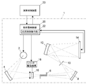
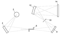
- FIG. 22 schematically shows the configuration of a multi-channel absorbance detector.
- the detector includes a light source 2 that emits measurement light, a flow cell 6 for flowing an eluate from an analysis column of a liquid chromatograph, a light detector 14 for detecting light, and light from the light source 2 to the flow cell 6.
- an optical system for guiding the light transmitted through the flow cell 6 to the photodetector 14 is provided.
- the optical system includes a mirror 4, a mirror 8, and a concave diffraction grating 12.
- the mirror 4 is disposed on the optical axis of the light emitted from the light source 2, and the flow cell 6 is disposed on the optical axis of the light reflected by the mirror 4.
- a mirror 8 is arranged on the optical axis of the light transmitted through the flow cell 6, and a slit 10 and a concave diffraction grating 12 are arranged at a position on the optical axis of the light reflected by the mirror 8, and are split by the concave diffraction grating 12.
- the light detector 14 is disposed at a position where the received light can be received.
- the light from the light source 2 is reflected by the mirror 4 and condensed on the flow cell 6, the light transmitted through the flow cell 6 is reflected by the mirror 8 and condensed on the slit 10, and the light passing through the slit 10 is concavely diffracted.
- the light is split by the grating 12 and imaged on the photodetector 14.
- the light source 2 is, for example, a deuterium lamp, and the photodetector 14 is a multichannel photodetector such as a photodiode array.
- the photodetector 14 detects a temporal change in the intensity of light for each predetermined wavelength range that has passed through the flow cell 6, and the detection signal is converted as a change in absorbance and sent to an arithmetic control device (not shown). Analysis data processing is performed. Absorbance data obtained from the data processing can be used to obtain an absorption spectrum for the qualification of the sample, or to quantify a specific component based on the relationship between the absorbance at a wavelength where the specific component is absorbed and the sample concentration. it can.
- Parts such as lenses and window plates are provided in the light passage part of the flow cell 6.
- ultraviolet light and visible light are often used. Therefore, a material that is transparent to ultraviolet light and visible light is used as a material for components such as lenses and window plates provided in the flow cell 6. Quartz glass is often used.
- the mirror 4, mirror 8, and diffraction grating 12 other than the flow cell are often made of aluminum as a reflective material. If light with strong energy continues to pass through these parts, the deterioration of these parts may progress and the light transmittance may decrease.
- an object of the present invention is to suppress deterioration of components and other optical elements constituting the flow cell.
- a first embodiment of a detector according to the present invention includes a light source that emits measurement light, a light detector for detecting light, a flow cell for flowing a sample to be measured, light from the light source to the flow cell, and a flow cell.
- a light irradiation control means for controlling the operation of the shutter mechanism so that the light shielding shutter is removed from the optical path only when the measurement is performed and the light shielding shutter is disposed on the optical path except when the measurement of the sample is performed.
- a second embodiment of the detector according to the present invention includes a light source for emitting measurement light, a flow cell for flowing a sample to be measured, an optical system for guiding light from the light source to the flow cell, and light detection for detecting light. And at least a part of the light in the wavelength range not used for measurement from the light irradiated to the flow cell when placed on the optical path of the light guided from the light source to the flow cell when the measurement of the sample is executed Or a neutral density filter having a light shielding characteristic.
- the liquid chromatograph according to the present invention includes an analysis channel, a sample introduction unit for introducing a sample into the analysis channel, a mobile phase solution feeding unit for feeding a mobile phase in the analysis channel, An analysis column is provided on the downstream side of the sample introduction section on the analysis flow path, and is separated from the sample introduced by the sample introduction section for each component, and is provided on the analysis flow path on the downstream side of the analysis column. And a detector for detecting the separated sample component, wherein the detector includes the first form or the second form of the detector according to the present invention.
- a shutter mechanism that can block the light from the light source to the flow cell by arranging a light blocking shutter on the optical path of the light guided from the light source to the flow cell, and the measurement of the sample
- the detector of the present invention at least a part of light in a wavelength range not used for measurement is dimmed or shielded from the light irradiated to the flow cell, which is disposed on the optical path of the light guided from the light source to the flow cell. Because it is equipped with a neutral density filter, it is possible to reduce the intensity of the light irradiated to the flow cell at least during sample measurement, and the deterioration of parts such as lenses and other optical elements that constitute the flow cell. Can be suppressed.
- the progress of deterioration of components such as lenses and other optical elements constituting the flow cell of the detector is suppressed, so that the reliability of the analysis is improved. Deterioration can be suppressed.
- the second embodiment of the detector according to the present invention and the liquid chromatograph provided with the second embodiment also provide an effect that the following problems can be improved.
- the low-concentration sample is greatly affected by alteration due to light irradiation, and the relationship between concentration and absorbance.
- concentration and absorbance There is a problem that the linearity of the sample deteriorates and the accuracy of quantification deteriorates.
- FIG. 15 is a graph showing an absorbance spectrum for each elapsed time from the start of light irradiation measured by sealing the anti-inflammatory analgesic as a sample in the flow cell after stopping the liquid feeding to the flow cell.
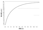
- FIG. 16 is a graph showing the temporal change in absorbance at a measurement wavelength of 260 nm in the data of FIG.
- the absorbance spectrum at the start of light irradiation can be referred to as the original absorbance spectrum of the sample.
- the absorbance spectrum changes with the passage of time from the start of light irradiation, and the absorbance at a wavelength of 260 nm increases with the passage of time. Yes.
- the sample is irradiated with light while passing through the flow cell, but the sample is altered within the passage time, and the influence becomes greater as the concentration is lower.
- the linearity at a wavelength of 260 nm deteriorates as shown by the graph in FIG.
- the light absorbance may decrease due to light irradiation, in which case the linearity deteriorates as shown in FIG. 17B.
- the reason why the linearity of absorbance deteriorates as the sample concentration decreases is that the amount of light received per molecule increases as the sample concentration decreases, so the proportion of denatured molecules increases and changes from the original absorbance. It is thought that it is from.
- the sample of the flow cell is irradiated with light other than the wavelength used for measuring the absorbance, and the sample contains a component that emits fluorescence when excited by light of such wavelength, the fluorescence emitted from that component
- the wavelength range used for the measurement of absorbance is included in this wavelength range, the linearity of the relationship between concentration and absorbance deteriorates due to the influence of the fluorescence, and there is also a problem that the accuracy of quantification deteriorates. For example, in the measurement of a sample having an absorption spectrum as shown in FIG.
- the above problems can be improved or solved by removing components not used for measurement from the light irradiated to the flow cell by the neutral density filter.
- the problem of deterioration of the sample due to the energy of the irradiated light can be improved by reducing the energy of the light irradiated to the flow cell by dimming or blocking a part of the light having a wavelength not used for measurement by the neutral density filter.
- the problem of fluorescence emitted from components contained in the sample can be solved by removing the wavelength components that excite such components with a neutral density filter.
- movement of the Example of FIG. 6 is a flowchart for explaining still another example of the shutter opening / closing operation of the embodiment of FIG. 1. 6 is a flowchart for explaining still another example of the shutter opening / closing operation of the embodiment of FIG. 1.
- a condensing mirror for condensing the light from the light source and guiding it to the flow cell may be provided between the light source and the flow cell. If such a condensing mirror is continuously irradiated with light having strong energy, the deterioration proceeds like the lens of the flow cell and the like, resulting in a problem that the reflectance decreases.
- the shutter mechanism may be configured to shield the light from the light source to the flow cell by arranging a light shielding shutter between the light source and the condenser mirror. Then, when the analysis of the sample is not performed, the light from the light source is not irradiated to the condenser mirror, and the irradiation time of the light to the condenser mirror is reduced and the deterioration of the condenser mirror is progressed. Can be suppressed.
- the neutral density filter is arranged between the light source and the collector mirror, the energy of the light irradiated to the collector mirror can be reduced. It is possible to suppress the progress of deterioration of the condenser mirror.
- the first and second embodiments of the detector according to the present invention include those in which the optical system has a configuration for guiding the light transmitted through the flow cell to the photodetector.
- the optical system has a configuration for guiding the light transmitted through the flow cell to the photodetector.
- the optical system has a configuration for guiding the light transmitted through the flow cell to the photodetector.
- the optical system has a configuration for guiding the light transmitted through the flow cell to the photodetector.
- the optical system has a configuration for guiding the light transmitted through the flow cell to the photodetector.
- the optical system has a configuration for guiding the light transmitted through the flow cell to the photodetector.
- the optical system has a configuration for guiding the light transmitted through the flow cell to the photodetector.
- the optical system has a configuration for guiding the light transmitted through the flow cell to the photodetector.
- the optical system has a configuration for guiding the light transmitted through the flow cell to the photo
- the detector is disposed on the optical path of the light guided from the light source to the flow cell, and the light irradiated to the flow cell is used in a wavelength region that is not used for the measurement.
- the optical system further includes a filter driving mechanism that performs an operation of disposing the neutral density filter on the optical path and an operation of removing the neutral density filter from the optical path
- the filter driving mechanism is a sample having a property of being altered at least by light irradiation.
- a neutral density filter is arranged on the optical path.
- the detector further includes a filter driving mechanism that performs an operation of disposing the neutral density filter on the optical path and an operation of removing it from the optical path, and the filter driving mechanism is at least by light irradiation
- the filter driving mechanism is at least by light irradiation
- Examples include a filter in which an attenuating filter is arranged on an optical path when measuring a sample having a property of changing quality.
- a sample introduction unit As an example of a preferred embodiment of a liquid chromatograph equipped with the first embodiment of the detector of the present invention, a sample introduction unit, a mobile phase liquid feeding unit, and a control unit that controls the operation by transmitting a control signal to the detector
- the light irradiation control means of the detector receives a signal for starting the analysis of the sample from the control unit, the light shielding shutter is removed from the optical path of the light from the light source, and the sample is analyzed from the control unit.
- a light-shielding shutter is arranged on the optical path when a signal for ending is received.
- the operation is performed by transmitting a control signal to the sample introduction part, the mobile phase liquid feeding part and the detector.
- the light irradiation control means of the detector further removes the light-shielding shutter from the light path of the light from the light source and receives the analysis when receiving a signal for starting the analysis of the sample from the control unit.
- the time elapsed since the start of the measurement is counted, and when the time required for the analysis has elapsed since the start of the analysis, a light shielding shutter is arranged on the optical path.
- the mobile phase liquid feeding unit is feeding the mobile phase while feeding the mobile phase. While the light irradiation control means of the detector is receiving a signal indicating that the mobile phase is being fed from the mobile phase liquid feeding unit, The light-shielding shutter is removed from the light path of the light from the light source, and the light-shielding shutter is arranged on the light path when the mobile phase liquid feeding unit stops receiving a signal indicating that the mobile phase is being fed. What is being done is mentioned.
- an arithmetic processing unit that performs arithmetic processing on a sample based on a detection signal obtained by the detector, and a light shielding shutter of the detector are provided on the optical path.
- a dark current data holding unit that holds a dark current value of a light detector element measured in a state of being arranged in the detector, and the arithmetic processing unit is a detector for measuring the sample in the arithmetic processing for the sample.
- the dark current value held in the dark current data holding unit may be subtracted from the detection signal obtained in the above and used for the arithmetic processing.
- the detector 1 includes a light source 2 that emits measurement light, a flow cell 6 for flowing an eluate from an analysis column of a liquid chromatograph, a light detector 14 for detecting light, and light from the light source 2 to the flow cell 6.
- An optical system that guides the light transmitted through the flow cell 6 to the photodetector 14 is provided.
- the optical system includes a mirror 4, a mirror 8, and a concave diffraction grating 12.
- the mirror 4 is disposed on the optical axis of the light emitted from the light source 2, and the flow cell 6 is disposed on the optical axis of the light reflected by the mirror 4.
- a mirror 8 is arranged on the optical axis of the light transmitted through the flow cell 6, and a slit 10 and a concave diffraction grating 12 are arranged at a position on the optical axis of the light reflected by the mirror 8, and are split by the concave diffraction grating 12.
- the light detector 14 is disposed at a position where the received light can be received.
- the light from the light source 2 is reflected by the mirror 4 and condensed on the flow cell 6, the light transmitted through the flow cell 6 is reflected by the mirror 8 and condensed on the slit 10, and the light passing through the slit 10 is concavely diffracted.
- the light is split by the grating 12 and imaged on the photodetector 14.
- the light source 2 is, for example, a deuterium lamp, and the photodetector 14 is a multichannel photodetector such as a photodiode array.
- FIG. 1 An example of the structure of the flow cell 6 is shown in FIG.
- a cell 36 is formed inside the housing 42.
- An inlet channel 38 is connected to one end of the cell 36, and an outlet channel 40 is connected to the other end of the cell 36.
- a lens 44 is disposed on the side of the light incident side of the cell 36 via a gasket 45, and the lens 44 and the gasket 45 are fixed to the housing 42 by a fixing screw 46.
- a flat window plate 48 is disposed on the side of the light emission side of the cell 36 via a gasket 49, and the window plate 48 and the gasket 49 are fixed to the housing 42 by a fixing screw 50.
- the lens 44 and the window plate 48 are made of, for example, synthetic quartz glass, and the gaskets 45 and 49 are made of a fluororesin.
- the photodetector 14 detects a temporal change in the intensity of light for each predetermined wavelength range that has passed through the flow cell 6, and the detection signal is converted as a change in absorbance so that the arithmetic control device 23, analysis data processing is performed.
- Absorbance data obtained from the data processing can be used to obtain an absorption spectrum for the qualification of the sample, or to quantify a specific component based on the relationship between the absorbance at a wavelength where the specific component is absorbed and the sample concentration. it can.
- a shutter 16 for shielding light from the light source 2 and a shutter drive mechanism 18 that can be disposed on or removed from the light path of the light from the light source 2 are provided.
- the shutter 16 is arranged on the optical path of the light from the light source 2 between the light source 2 and the condenser mirror 4.
- the shutter 16 and the shutter drive mechanism 18 constitute a shutter mechanism.
- disposing the shutter 16 on the optical path of the light from the light source 2 is expressed as “closing”, and removing the shutter 16 from the optical path is expressed as “opening”.
- An example of the shutter drive mechanism 18 is to rotationally drive a shutter 16 that shields light by a motor 18a, as shown in FIG.
- the position of the shutter 16 is controlled by a motor drive unit 18b that controls the rotation of the motor 18a by applying a voltage to the motor 18a.
- the configuration of the shutter mechanism is not limited to this, and any configuration may be used as long as the shutter 16 can be opened and closed.
- the detector 1 includes a detector control unit 20.
- the detector control unit 20 is realized by a computer, and controls the light source 2, the shutter drive mechanism 18, and the photodetector 14 based on a control signal given from an external arithmetic control device 23. Further, the detection signal obtained by the photodetector 14 is input to the arithmetic control device 23 via the detector control unit 20, and the arithmetic control device 23 performs an operation for obtaining the absorbance and the like.
- the arithmetic control device 23 will be described later.
- the detector control unit 20 includes light irradiation control means 22 for controlling the lighting of the light source 2 and the driving of the shutter by the shutter driving mechanism 18.
- the light irradiation control means 22 is configured to open the shutter 16 only when measuring the absorbance of the sample.
- the light irradiation control means 22 keeps the shutter 16 closed until it receives a sample analysis start signal from the arithmetic and control unit 23, and receives the analysis start signal.
- the shutter 16 is configured to open.
- the detector control part 20 is comprised so that the shutter 16 may be closed again, when the signal of the completion
- the operation of closing the shutter 16 after the analysis is not necessarily performed based on the signal from the arithmetic control device 23 as described above.
- the detector control unit 20 receives an analysis start signal from the arithmetic control device 23, it also receives information on the time required for analysis, and the detector control unit 20 starts the analysis.
- the light irradiation control means 22 may be configured so as to measure the time from the time until the shutter 16 is closed when the time required for analysis has elapsed.
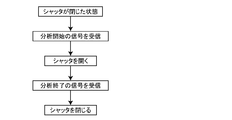
- the light irradiation control means 22 of the detector control unit 20 starts a series of analyzes from the arithmetic control device 23 as shown in the flowchart of FIG.
- the shutter 16 is opened based on this signal, and the shutter 16 is closed based on the end signal of a series of analyzes from the arithmetic and control unit 23.
- the operation of closing the shutter 16 after the end of a series of analyzes in the case of analyzing a plurality of samples continuously does not necessarily have to be performed based on the signal from the arithmetic and control unit 23 as described above.
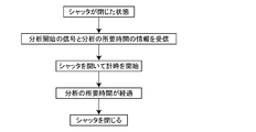
- the detector control unit 20 receives an analysis start signal from the arithmetic control device 23, it also receives information on the analysis schedule set in the arithmetic control device 23.
- the detector control unit 20 receives information indicating that the analysis is the last analysis and the time required for the analysis from the arithmetic and control unit 23, and the time required after receiving the signal for starting the last analysis.
- the light irradiation control means 22 may be configured to measure the time until the passage of time and close the shutter 16 when the last analysis is completed.
- An analysis column 32 and a detector 1 for separation are provided.
- the arithmetic control device 23 has functions of an arithmetic processing unit and a control unit, and controls the operations of the liquid feed pump 26, the sample injection unit 30, and the detector 1, and based on signals obtained by the detector 1. Calculation to obtain absorbance and the like is performed.
- the arithmetic and control unit 23 can be realized by, for example, a PC (personal computer) or a dedicated computer, as well as those including those computers and a system controller.
- the system controller is interposed between a PC or a dedicated computer and each device such as the liquid feed pump 26, the sample injection unit 30, and the detector 1, and sets operations and operating conditions for each of these devices.
- An analysis schedule and analysis conditions are set in the arithmetic and control unit 23.
- an operation start signal is given from the arithmetic and control unit 23 to the detector 1 and the liquid feed pump 26.
- the detector 1 closes the shutter 16 and turns on the light source 2.
- the liquid feed pump 26 starts to feed the mobile phase. Then, it waits for a fixed time until the emitted light quantity of the light source 2 of the detector 1 is stabilized.
- an analysis start signal is given from the arithmetic and control unit 23 to the detector 1 and the sample injection unit 30.
- the detector 1 opens the shutter 16 and irradiates the flow cell 6 with light from the light source 2.
- the sample injection unit 30 injects the sample into the analysis flow path 24. The sample injected into the analysis channel 24 is separated for each component in the analysis column 32, and then introduced into the flow cell 6 of the detector 1, whereby the absorbance is measured and the component concentration is quantified.
- the next sample is injected into the analysis flow path 24 by the sample injection unit 30 and analyzed.
- the arithmetic and control unit 23 gives an analysis end signal to the detector 1, and the detector 1 receiving the analysis end signal closes the shutter 16 and puts it in the flow cell 6. Blocks the irradiated light.
- the arithmetic and control unit 23 gives an analysis start signal to the detector 1 and the sample injection unit 30 based on the new analysis schedule, whereby the detector 1 opens the shutter 16 and the sample injection The unit 30 sequentially injects the sample into the analysis channel 24 and executes analysis of the analysis schedule.
- the arithmetic and control unit 23 gives an operation end signal to the detector 1 and the liquid feed pump 26. Upon receiving the operation end signal, the detector 1 turns off the light source 2 and the liquid feed pump 26 stops the mobile phase liquid feed. Thereby, the operation of the liquid chromatograph is completed.
- the detector and the liquid chromatograph of the present invention are not limited to those in which the opening and closing of the shutter 16 of the detector 1 is performed based on the signal from the arithmetic control device 23 and the elapsed time from the start of analysis.
- a signal indicating that the mobile phase is being fed is transmitted to the detector control unit 20 of the detector 1.
- the detector control unit 20 opens the shutter 16 while receiving a signal from the liquid feeding pump 26, and closes the shutter 16 when no signal is received. Good.
- the advantage that the light incident on the photodetector 14 can be blocked by closing the shutter 16 without turning off the light source 2 makes it possible to provide the apparatus with a function of eliminating the influence of the dark current of the elements of the photodetector 14. It is.
- the dark current value of each element of the photodetector 14 is determined by measuring the signal of each element of the multi-channel photodetector 14 with the shutter 16 closed and the light incident on the photodetector 14 blocked. Can be measured. The measured value can be corrected using the dark current value.
- a dark current data holding unit 23 a for holding the measured dark current value is provided in the arithmetic control device 23. Then, when calculating the absorbance, as shown in the flowchart of FIG. 10, the detection signal data of each element of the photodetector 14 with respect to the sample with the shutter 16 opened is collected, and the dark current is obtained. The dark current value held in the data holding unit 23a is subtracted from the collected detection signal value, and the calculation for obtaining the absorbance of the sample component is performed using the detection signal data after the dark current value is subtracted. Thereby, the light absorbency which reduced the influence of the dark current of the photodetector 14 can be calculated
- the dark current data holding unit 23 a is provided in the arithmetic control device 23, but the dark current data holding unit 23 a is provided by a data memory or other storage device provided in the detector control unit 20. Can also be realized.
- the shutter 16 is arranged between the light source 2 and the condenser mirror 4 when the shutter 16 is closed, but the present invention is not limited to this. 12, a shutter 16 may be disposed between the mirror 4 and the flow cell 6. In short, even when other optical components are provided, when the shutter 16 is closed, the shutter 16 is disposed at least on the optical path of the light from the light source 2 between the light source 2 and the flow cell 6. Well, by doing so, it is possible to suppress the progress of deterioration of components such as lenses, the mirror 8 and the diffraction grating 12 constituting the flow cell 6. As in the embodiment of FIG. 1, by arranging the shutter 16 closer to the light source 2 than other optical components, it is possible to suppress the progress of deterioration of more optical components such as the condensing mirror 4. it can.
- the light from the light source 2 is guided to the flow cell 6, and the light transmitted through the flow cell 6 is dispersed by the spectroscope 12 and detected by the photodetector 14.
- the detector according to the present invention is not limited to this.
- the light after the light from the light source is separated by the spectroscope is guided to the flow cell, and the light transmitted through the flow cell is detected by the photodetector.
- the present invention can also be applied to a pre-spectroscopic spectrophotometer detected by the above method.
- FIG. 14 is a schematic configuration diagram showing an embodiment in which the present invention is applied to a pre-spectral spectrophotometer.
- the detector 1a of this embodiment includes a mirror 40, a slit 42, a mirror 44, a diffraction grating 46, and a mirror 50 as an optical system for guiding the light from the light source 2 to the flow cell 6.
- the light from the light source 2 is condensed on the slit 42 by the mirror 40, and the light transmitted through the slit 42 is reflected by the mirror 44 and enters the diffraction grating 46.
- the light incident on the diffraction grating 46 is dispersed in the wavelength direction, and the wavelength component used for measuring the absorbance of the sample is guided to the mirror 50.
- the diffraction grating 46 is rotated about a rotation axis 47 by a diffraction grating rotating mechanism 48.
- the relationship between the rotation angle of the diffraction grating 46 and the wavelength of the light extracted toward the flow cell 6 is set in advance, and the detector control unit 20a extracts the light of the wavelength used for measurement and irradiates the flow cell 6 with it.
- the installation angle is adjusted by rotating the diffraction grating 46.
- the light split by the diffraction grating 46 and incident on the mirror 50 is reflected by the mirror 50 and applied to the flow cell 6, and the light transmitted through the flow cell 6 is detected by the sample-side photodetector 54 provided immediately after the flow cell 6.
- a beam splitter 52 is installed between the mirror 50 and the flow cell 6.
- the beam splitter 52 extracts a part of the light traveling from the mirror 50 toward the flow cell 6 and guides it to the reference side photodetector 56, and the reference side photodetector 56 emits a part of the light emitted to the flow cell 6. Measured.
- the detection signal of the reference-side photodetector 56 is used to correct the influence due to the variation in the amount of light irradiated to the flow cell 6.
- the temporal change in the intensity of the light transmitted through the flow cell 6 is detected in the sample-side photodetector 54, and the detection signal is converted as an absorbance change and sent to the arithmetic control device 23a.
- the arithmetic and control unit 23a obtains the absorbance of the sample flowing through the flow cell 6 based on the detection signals of the sample-side photodetector 54 and the reference-side photodetector 56, and uses a calibration curve representing the relationship between the absorbance and the sample concentration prepared in advance. Based on this, the specific component is quantified.
- a shutter 16 is arranged on the optical path of light from the light source 2 toward the mirror 40.
- the shutter 16 is disposed on the optical path or removed from the optical path by the shutter driving mechanism 18.
- mirror 40, mirror 44, diffraction grating 46 and mirror 50 constituting the optical system of the detector 1a by closing the shutter 16 when the sample is not analyzed while the light source 2 is lit, It is possible to suppress the progress of deterioration of the lens provided in the flow cell 6.
- the position where the shutter 16 is disposed is not limited to the position between the light source 2 and the mirror 40, and the light source 2, the flow cell 6, and the like. As long as it is on the optical path of the light from the light source 2 between them, it is possible to suppress the progress of deterioration of components such as optical components and lenses of the flow cell 6 on the rear side of the shutter 16.
- the detector 1b of this embodiment is obtained by adding a neutral density filter (hereinafter referred to as a filter) 60 to the detector 1 of FIG. 1 and changing the shutter driving mechanism 18 to a shutter and filter driving mechanism 62.
- a filter neutral density filter
- Other configurations are the same as those of the detector 1 of FIG. 1, and a detailed description thereof is omitted here.
- a shutter 16 and a filter 60 are arranged on the optical path of light from the light source 2 toward the mirror 4.
- the shutter 16 and the filter 60 are arranged on the optical path of the light from the light source 2 by the shutter and filter driving mechanism 62 or are removed from the optical path.
- the shutter 16 and the filter 60 are driven by a common mechanism called the shutter and filter drive mechanism 62, but may be driven by separate drive mechanisms. .
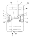
- FIG. 16 An example of the configuration of the shutter 16, the filter 60, the shutter, and the filter driving mechanism 62 is shown in FIG.
- the filter 60 is provided as a partial region of the shutter 16 and is driven to rotate by a motor 62a. By rotating the motor 62a, the shutter 16 is disposed on the optical path of the light from the light source 2, the filter 60 is disposed on the optical path of the light from the light source 2, and both the shutter 16 and the filter 60 are separated from the light source 2. It is possible to make it not placed on the optical path of the light.
- the shutter 16 is disposed on the optical path of the light from the light source 2, and the optical components constituting the optical system are deteriorated. Is prevented.
- the filter 60 is disposed on the optical path of the light from the light source 2, thereby reducing the energy of the light from the light source 2 at the time of analyzing the sample, and the subsequent stage. The deterioration of the sample in the flow cell 6 due to light irradiation can be suppressed while the deterioration of the optical component on the side can be suppressed. Further, in the case where the sample flowing through the flow cell 6 has a property that does not change due to light irradiation, it is possible to perform high-sensitivity measurement without arranging the filter 60 on the optical path of the light from the light source 2.
- a sample having an absorbance spectrum as shown in FIG. 15 is quantified by measuring absorbance at a wavelength of 260 nm.
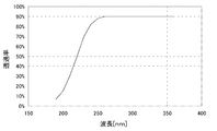
- this sample has strong absorption on the shorter wavelength side than 260 nm used for measurement, and particularly has strong absorption on the shorter wavelength side than 220 nm. Therefore, as the wavelength characteristics of the filter used as the filter 60, it is preferable to use a filter having characteristics that hardly transmit light on the short wavelength side from around 220 nm as shown in FIG.
- the filter 60 light having a wavelength component that is absorbed by the sample and not used for measurement can be removed by the filter 60, and deterioration of the sample due to light irradiation can be suppressed.
- a plurality of types of filters used as the filter 60 are prepared, and the filter to be used may be determined according to the characteristics of the sample to be measured.
- the absorbance spectrum of the sample component to be analyzed is known in advance, a filter that transmits light in the vicinity of the wavelength used for measurement within the wavelength range with the absorption and attenuates wavelength components not used for measurement Select. Even if the absorbance spectrum of the sample component to be analyzed is not known, the multi-channel absorbance detector can easily measure the spectrum. Therefore, the absorbance spectrum of the target component is measured without the filter 60 being installed in the optical path.
- the filter wavelength and transmittance characteristics are selected as in the case where the absorbance spectrum of the target component is known.
- the wavelength range used for measurement it is preferable to select a filter that attenuates light on the short wavelength side. Since the light on the short wavelength side has stronger energy than the light on the long wavelength side, the wavelength range used for measurement can be selected by selecting a filter that attenuates light on the short wavelength side rather than the wavelength range used for measurement. It is possible to more efficiently suppress the deterioration of the sample component than selecting a filter that attenuates light on the longer wavelength side.
- the filter having the light transmission characteristics as shown in FIG. 20 has some transmittance even in a short wavelength region of 220 nm or less, the filter is arranged on the optical path using light in the wavelength region in which the filter absorbs.
- the absorbance spectrum of the sample can be obtained by taking the difference between the absorbance spectrum of the mobile phase and the sample in the state, and the absorbance spectrum of the sample can be accurately measured while suppressing the alteration of the sample.
- a filter having a light transmission characteristic as shown in FIG. It is possible to suppress the generation of fluorescence that inhibits the absorbance measurement.
- the filter 60 is arranged between the light source 2 and the condenser mirror 4, but the present invention is not limited to this, and between the light source 2 and the flow cell 6. Any position on the optical path of the light irradiated to the flow cell 6 may be used. As in the embodiment of FIG. 18, the filter 60 is arranged at a position closer to the light source 2 than other optical components, thereby suppressing the progress of deterioration of more optical components such as the condenser mirror 4. it can.
- the filter 60 is driven by a driving mechanism, and is arranged on or removed from the optical path of the light from the light source 2, but the present invention is not limited to this. Instead, the filter 60 may be always arranged on the optical path of the light from the light source 2. In that case, it can be realized by forming the lens 44 of the flow cell 6 of FIG. 11 with the material of the filter 60 of FIG. Thereby, without increasing the number of parts constituting the detector, it is possible to suppress the deterioration of the optical parts on the subsequent stage and the deterioration of the sample. Further, as shown in FIG. 21, the same effect can be obtained even if the filter 60 is attached to the entrance window side of the flow cell 6a.
Abstract
La présente invention concerne un obturateur (16) (obturateur de blocage de la lumière) destiné à bloquer la lumière provenant d'une source lumineuse (2), ainsi qu'un mécanisme (18) d'entraînement d'obturateur, destiné à déplacer l'obturateur (16), entre une position sur le parcours optique de la lumière émise par la source lumineuse (2) et entre la source lumineuse (2) et un miroir (4) de recueil de la lumière et une position extérieure au parcours optique. Une unité (20) de commande de détecteur est dotée d'un moyen de commande (22) de rayonnement lumineux, destiné à commander l'éclairage de la source lumineuse (2) et l'entraînement de l'obturateur par le mécanisme (18) d'entraînement de l'obturateur. Le moyen de commande (22) de rayonnement lumineux est conçu pour n'ouvrir l'obturateur (16) que lorsque l'absorbance d'un échantillon est mesurée.
Priority Applications (1)
| Application Number | Priority Date | Filing Date | Title |
|---|---|---|---|
| PCT/JP2012/057582 WO2013140617A1 (fr) | 2012-03-23 | 2012-03-23 | Détecteur et chromatographe liquide muni du détecteur |
Applications Claiming Priority (1)
| Application Number | Priority Date | Filing Date | Title |
|---|---|---|---|
| PCT/JP2012/057582 WO2013140617A1 (fr) | 2012-03-23 | 2012-03-23 | Détecteur et chromatographe liquide muni du détecteur |
Publications (1)
| Publication Number | Publication Date |
|---|---|
| WO2013140617A1 true WO2013140617A1 (fr) | 2013-09-26 |
Family
ID=49222110
Family Applications (1)
| Application Number | Title | Priority Date | Filing Date |
|---|---|---|---|
| PCT/JP2012/057582 WO2013140617A1 (fr) | 2012-03-23 | 2012-03-23 | Détecteur et chromatographe liquide muni du détecteur |
Country Status (1)
| Country | Link |
|---|---|
| WO (1) | WO2013140617A1 (fr) |
Cited By (8)
| Publication number | Priority date | Publication date | Assignee | Title |
|---|---|---|---|---|
| WO2018131279A1 (fr) * | 2017-01-16 | 2018-07-19 | 株式会社島津製作所 | Détecteur à chromatographe en phase liquide |
| JPWO2018020535A1 (ja) * | 2016-07-25 | 2018-12-27 | 株式会社島津製作所 | 分析装置 |
| WO2020148878A1 (fr) * | 2019-01-17 | 2020-07-23 | 株式会社島津製作所 | Détecteur d'absorbance pour chromatographe et procédé de détection de position standard |
| JP2020114154A (ja) * | 2019-01-16 | 2020-07-27 | 株式会社島津製作所 | クロマトグラフ装置およびロードスイッチ回路 |
| CN111829967A (zh) * | 2019-04-19 | 2020-10-27 | 株式会社堀场先进技术 | 光学分析装置 |
| WO2023127488A1 (fr) * | 2021-12-27 | 2023-07-06 | 東京エレクトロン株式会社 | Dispositif et procédé de détection de matières étrangères |
| WO2023127487A1 (fr) * | 2021-12-27 | 2023-07-06 | 東京エレクトロン株式会社 | Dispositif de détection de corps étranger et procédé de détection de corps étranger |
| JP7462655B2 (ja) | 2019-01-18 | 2024-04-05 | アーペー2エ | ラマン分光法による微量のガスの検出に適した、光帰還を有する共振光学キャビティシステム |
Citations (5)
| Publication number | Priority date | Publication date | Assignee | Title |
|---|---|---|---|---|
| JPH03108648A (ja) * | 1989-09-22 | 1991-05-08 | Hitachi Ltd | 表面状態評価方法およびその装置 |
| JP2008002849A (ja) * | 2006-06-20 | 2008-01-10 | Olympus Corp | 分析装置および容器 |
| JP2008111834A (ja) * | 2006-10-06 | 2008-05-15 | Shiseido Co Ltd | 紫外線防御効果の評価方法及び評価装置 |
| JP2009145182A (ja) * | 2007-12-13 | 2009-07-02 | Shimadzu Corp | 分析システム |
| JP2012032307A (ja) * | 2010-07-30 | 2012-02-16 | Shimadzu Corp | 分光光度計 |
-
2012
- 2012-03-23 WO PCT/JP2012/057582 patent/WO2013140617A1/fr active Application Filing
Patent Citations (5)
| Publication number | Priority date | Publication date | Assignee | Title |
|---|---|---|---|---|
| JPH03108648A (ja) * | 1989-09-22 | 1991-05-08 | Hitachi Ltd | 表面状態評価方法およびその装置 |
| JP2008002849A (ja) * | 2006-06-20 | 2008-01-10 | Olympus Corp | 分析装置および容器 |
| JP2008111834A (ja) * | 2006-10-06 | 2008-05-15 | Shiseido Co Ltd | 紫外線防御効果の評価方法及び評価装置 |
| JP2009145182A (ja) * | 2007-12-13 | 2009-07-02 | Shimadzu Corp | 分析システム |
| JP2012032307A (ja) * | 2010-07-30 | 2012-02-16 | Shimadzu Corp | 分光光度計 |
Cited By (17)
| Publication number | Priority date | Publication date | Assignee | Title |
|---|---|---|---|---|
| JPWO2018020535A1 (ja) * | 2016-07-25 | 2018-12-27 | 株式会社島津製作所 | 分析装置 |
| JPWO2018131279A1 (ja) * | 2017-01-16 | 2019-06-27 | 株式会社島津製作所 | 液体クロマトグラフ用検出器 |
| CN109952501A (zh) * | 2017-01-16 | 2019-06-28 | 株式会社岛津制作所 | 液相色谱仪用检测器 |
| WO2018131279A1 (fr) * | 2017-01-16 | 2018-07-19 | 株式会社島津製作所 | Détecteur à chromatographe en phase liquide |
| US11480553B2 (en) | 2017-01-16 | 2022-10-25 | Shimadzu Corporation | Liquid chromatography detector |
| US11451050B2 (en) | 2019-01-16 | 2022-09-20 | Shimadzu Corporation | Chromatograph apparatus and load switch circuit |
| JP2020114154A (ja) * | 2019-01-16 | 2020-07-27 | 株式会社島津製作所 | クロマトグラフ装置およびロードスイッチ回路 |
| JP7156047B2 (ja) | 2019-01-16 | 2022-10-19 | 株式会社島津製作所 | クロマトグラフ装置およびロードスイッチ回路 |
| WO2020148878A1 (fr) * | 2019-01-17 | 2020-07-23 | 株式会社島津製作所 | Détecteur d'absorbance pour chromatographe et procédé de détection de position standard |
| JPWO2020148878A1 (ja) * | 2019-01-17 | 2021-10-14 | 株式会社島津製作所 | クロマトグラフ用吸光度検出器および基準位置検出方法 |
| JP7168917B2 (ja) | 2019-01-17 | 2022-11-10 | 株式会社島津製作所 | クロマトグラフ用吸光度検出器および基準位置検出方法 |
| US11933772B2 (en) | 2019-01-17 | 2024-03-19 | Shimadzu Corporation | Absorbance detector for chromatograph and reference position detection method |
| JP7462655B2 (ja) | 2019-01-18 | 2024-04-05 | アーペー2エ | ラマン分光法による微量のガスの検出に適した、光帰還を有する共振光学キャビティシステム |
| CN111829967A (zh) * | 2019-04-19 | 2020-10-27 | 株式会社堀场先进技术 | 光学分析装置 |
| CN111829967B (zh) * | 2019-04-19 | 2024-03-12 | 株式会社堀场先进技术 | 光学分析装置 |
| WO2023127488A1 (fr) * | 2021-12-27 | 2023-07-06 | 東京エレクトロン株式会社 | Dispositif et procédé de détection de matières étrangères |
| WO2023127487A1 (fr) * | 2021-12-27 | 2023-07-06 | 東京エレクトロン株式会社 | Dispositif de détection de corps étranger et procédé de détection de corps étranger |
Similar Documents
| Publication | Publication Date | Title |
|---|---|---|
| WO2013140617A1 (fr) | Détecteur et chromatographe liquide muni du détecteur | |
| JP6075788B2 (ja) | 蛍光および吸収分析のシステムおよび方法 | |
| US7787120B2 (en) | Spectrophotometer and liquid chromatography system | |
| EP3301434A1 (fr) | Étalonnage indépendant des compositions de capteurs de gaz par infrarouges non dispersifs | |
| EP2477024B1 (fr) | Analyseur | |
| JP2016121926A (ja) | 光学分析装置 | |
| WO2016129033A1 (fr) | Spectrophotomètre à canaux multiples et procédé de traitement de données pour spectrophotomètre à canaux multiples | |
| JPH03202754A (ja) | 多元素同時分析原子吸光分光光度計 | |
| US10876887B2 (en) | Spectroscopic detector | |
| JPH06273333A (ja) | 分光蛍光光度計 | |
| KR20150115036A (ko) | 비분산자외선을 이용한 no/no2 멀티측정기 및 no/no2 멀티 측정방법 | |
| KR101381618B1 (ko) | 비분산 자외선 흡수법을 이용한 멀티가스 분석장치 | |
| JPS6250641A (ja) | 吸光光度計を備えた分析装置 | |
| JP6385299B2 (ja) | 液体クロマトグラフ用遠紫外吸光度検出装置 | |
| JPWO2013140617A1 (ja) | 検出器及びその検出器を備えた液体クロマトグラフ | |
| RU126136U1 (ru) | Анализатор состава природного газа | |
| US8717557B2 (en) | Spectrophotometer and method for determining performance thereof | |
| US8913240B2 (en) | Fluorescence spectrophotometer | |
| KR100403440B1 (ko) | 분광분석장치 | |
| WO2019069526A1 (fr) | Spectromètre | |
| KR101317059B1 (ko) | 멀티가스 분석용 자외선 측정장치 | |
| JP4146761B2 (ja) | 蛍光測定装置 | |
| JP4486805B2 (ja) | 分光分析装置 | |
| WO2018003045A1 (fr) | Diviseur de faisceau à fonction d'ouverture, et détecteur muni dudit diviseur de faisceau. | |
| EP1785719A1 (fr) | Méthode de détection optique et détecteur optique |
Legal Events
| Date | Code | Title | Description |
|---|---|---|---|
| 121 | Ep: the epo has been informed by wipo that ep was designated in this application |
Ref document number: 12871990 Country of ref document: EP Kind code of ref document: A1 |
|
| ENP | Entry into the national phase |
Ref document number: 2014505944 Country of ref document: JP Kind code of ref document: A |
|
| NENP | Non-entry into the national phase |
Ref country code: DE |
|
| 122 | Ep: pct application non-entry in european phase |
Ref document number: 12871990 Country of ref document: EP Kind code of ref document: A1 |