WO2013129455A1 - 車両用駆動装置 - Google Patents
車両用駆動装置 Download PDFInfo
- Publication number
- WO2013129455A1 WO2013129455A1 PCT/JP2013/055083 JP2013055083W WO2013129455A1 WO 2013129455 A1 WO2013129455 A1 WO 2013129455A1 JP 2013055083 W JP2013055083 W JP 2013055083W WO 2013129455 A1 WO2013129455 A1 WO 2013129455A1
- Authority
- WO
- WIPO (PCT)
- Prior art keywords
- pressure
- clutch
- port
- oil passage
- lubricating oil
- Prior art date
Links
Images

Classifications
-
- B—PERFORMING OPERATIONS; TRANSPORTING
- B60—VEHICLES IN GENERAL
- B60K—ARRANGEMENT OR MOUNTING OF PROPULSION UNITS OR OF TRANSMISSIONS IN VEHICLES; ARRANGEMENT OR MOUNTING OF PLURAL DIVERSE PRIME-MOVERS IN VEHICLES; AUXILIARY DRIVES FOR VEHICLES; INSTRUMENTATION OR DASHBOARDS FOR VEHICLES; ARRANGEMENTS IN CONNECTION WITH COOLING, AIR INTAKE, GAS EXHAUST OR FUEL SUPPLY OF PROPULSION UNITS IN VEHICLES
- B60K6/00—Arrangement or mounting of plural diverse prime-movers for mutual or common propulsion, e.g. hybrid propulsion systems comprising electric motors and internal combustion engines ; Control systems therefor, i.e. systems controlling two or more prime movers, or controlling one of these prime movers and any of the transmission, drive or drive units Informative references: mechanical gearings with secondary electric drive F16H3/72; arrangements for handling mechanical energy structurally associated with the dynamo-electric machine H02K7/00; machines comprising structurally interrelated motor and generator parts H02K51/00; dynamo-electric machines not otherwise provided for in H02K see H02K99/00
- B60K6/20—Arrangement or mounting of plural diverse prime-movers for mutual or common propulsion, e.g. hybrid propulsion systems comprising electric motors and internal combustion engines ; Control systems therefor, i.e. systems controlling two or more prime movers, or controlling one of these prime movers and any of the transmission, drive or drive units Informative references: mechanical gearings with secondary electric drive F16H3/72; arrangements for handling mechanical energy structurally associated with the dynamo-electric machine H02K7/00; machines comprising structurally interrelated motor and generator parts H02K51/00; dynamo-electric machines not otherwise provided for in H02K see H02K99/00 the prime-movers consisting of electric motors and internal combustion engines, e.g. HEVs
- B60K6/22—Arrangement or mounting of plural diverse prime-movers for mutual or common propulsion, e.g. hybrid propulsion systems comprising electric motors and internal combustion engines ; Control systems therefor, i.e. systems controlling two or more prime movers, or controlling one of these prime movers and any of the transmission, drive or drive units Informative references: mechanical gearings with secondary electric drive F16H3/72; arrangements for handling mechanical energy structurally associated with the dynamo-electric machine H02K7/00; machines comprising structurally interrelated motor and generator parts H02K51/00; dynamo-electric machines not otherwise provided for in H02K see H02K99/00 the prime-movers consisting of electric motors and internal combustion engines, e.g. HEVs characterised by apparatus, components or means specially adapted for HEVs
- B60K6/38—Arrangement or mounting of plural diverse prime-movers for mutual or common propulsion, e.g. hybrid propulsion systems comprising electric motors and internal combustion engines ; Control systems therefor, i.e. systems controlling two or more prime movers, or controlling one of these prime movers and any of the transmission, drive or drive units Informative references: mechanical gearings with secondary electric drive F16H3/72; arrangements for handling mechanical energy structurally associated with the dynamo-electric machine H02K7/00; machines comprising structurally interrelated motor and generator parts H02K51/00; dynamo-electric machines not otherwise provided for in H02K see H02K99/00 the prime-movers consisting of electric motors and internal combustion engines, e.g. HEVs characterised by apparatus, components or means specially adapted for HEVs characterised by the driveline clutches
- B60K6/387—Actuated clutches, i.e. clutches engaged or disengaged by electric, hydraulic or mechanical actuating means
-
- B—PERFORMING OPERATIONS; TRANSPORTING
- B60—VEHICLES IN GENERAL
- B60W—CONJOINT CONTROL OF VEHICLE SUB-UNITS OF DIFFERENT TYPE OR DIFFERENT FUNCTION; CONTROL SYSTEMS SPECIALLY ADAPTED FOR HYBRID VEHICLES; ROAD VEHICLE DRIVE CONTROL SYSTEMS FOR PURPOSES NOT RELATED TO THE CONTROL OF A PARTICULAR SUB-UNIT
- B60W20/00—Control systems specially adapted for hybrid vehicles
- B60W20/40—Controlling the engagement or disengagement of prime movers, e.g. for transition between prime movers
-
- B—PERFORMING OPERATIONS; TRANSPORTING
- B60—VEHICLES IN GENERAL
- B60K—ARRANGEMENT OR MOUNTING OF PROPULSION UNITS OR OF TRANSMISSIONS IN VEHICLES; ARRANGEMENT OR MOUNTING OF PLURAL DIVERSE PRIME-MOVERS IN VEHICLES; AUXILIARY DRIVES FOR VEHICLES; INSTRUMENTATION OR DASHBOARDS FOR VEHICLES; ARRANGEMENTS IN CONNECTION WITH COOLING, AIR INTAKE, GAS EXHAUST OR FUEL SUPPLY OF PROPULSION UNITS IN VEHICLES
- B60K6/00—Arrangement or mounting of plural diverse prime-movers for mutual or common propulsion, e.g. hybrid propulsion systems comprising electric motors and internal combustion engines ; Control systems therefor, i.e. systems controlling two or more prime movers, or controlling one of these prime movers and any of the transmission, drive or drive units Informative references: mechanical gearings with secondary electric drive F16H3/72; arrangements for handling mechanical energy structurally associated with the dynamo-electric machine H02K7/00; machines comprising structurally interrelated motor and generator parts H02K51/00; dynamo-electric machines not otherwise provided for in H02K see H02K99/00
- B60K6/20—Arrangement or mounting of plural diverse prime-movers for mutual or common propulsion, e.g. hybrid propulsion systems comprising electric motors and internal combustion engines ; Control systems therefor, i.e. systems controlling two or more prime movers, or controlling one of these prime movers and any of the transmission, drive or drive units Informative references: mechanical gearings with secondary electric drive F16H3/72; arrangements for handling mechanical energy structurally associated with the dynamo-electric machine H02K7/00; machines comprising structurally interrelated motor and generator parts H02K51/00; dynamo-electric machines not otherwise provided for in H02K see H02K99/00 the prime-movers consisting of electric motors and internal combustion engines, e.g. HEVs
- B60K6/42—Arrangement or mounting of plural diverse prime-movers for mutual or common propulsion, e.g. hybrid propulsion systems comprising electric motors and internal combustion engines ; Control systems therefor, i.e. systems controlling two or more prime movers, or controlling one of these prime movers and any of the transmission, drive or drive units Informative references: mechanical gearings with secondary electric drive F16H3/72; arrangements for handling mechanical energy structurally associated with the dynamo-electric machine H02K7/00; machines comprising structurally interrelated motor and generator parts H02K51/00; dynamo-electric machines not otherwise provided for in H02K see H02K99/00 the prime-movers consisting of electric motors and internal combustion engines, e.g. HEVs characterised by the architecture of the hybrid electric vehicle
- B60K6/48—Parallel type
-
- B—PERFORMING OPERATIONS; TRANSPORTING
- B60—VEHICLES IN GENERAL
- B60W—CONJOINT CONTROL OF VEHICLE SUB-UNITS OF DIFFERENT TYPE OR DIFFERENT FUNCTION; CONTROL SYSTEMS SPECIALLY ADAPTED FOR HYBRID VEHICLES; ROAD VEHICLE DRIVE CONTROL SYSTEMS FOR PURPOSES NOT RELATED TO THE CONTROL OF A PARTICULAR SUB-UNIT
- B60W10/00—Conjoint control of vehicle sub-units of different type or different function
- B60W10/02—Conjoint control of vehicle sub-units of different type or different function including control of driveline clutches
-
- B—PERFORMING OPERATIONS; TRANSPORTING
- B60—VEHICLES IN GENERAL
- B60W—CONJOINT CONTROL OF VEHICLE SUB-UNITS OF DIFFERENT TYPE OR DIFFERENT FUNCTION; CONTROL SYSTEMS SPECIALLY ADAPTED FOR HYBRID VEHICLES; ROAD VEHICLE DRIVE CONTROL SYSTEMS FOR PURPOSES NOT RELATED TO THE CONTROL OF A PARTICULAR SUB-UNIT
- B60W10/00—Conjoint control of vehicle sub-units of different type or different function
- B60W10/04—Conjoint control of vehicle sub-units of different type or different function including control of propulsion units
- B60W10/06—Conjoint control of vehicle sub-units of different type or different function including control of propulsion units including control of combustion engines
-
- B—PERFORMING OPERATIONS; TRANSPORTING
- B60—VEHICLES IN GENERAL
- B60W—CONJOINT CONTROL OF VEHICLE SUB-UNITS OF DIFFERENT TYPE OR DIFFERENT FUNCTION; CONTROL SYSTEMS SPECIALLY ADAPTED FOR HYBRID VEHICLES; ROAD VEHICLE DRIVE CONTROL SYSTEMS FOR PURPOSES NOT RELATED TO THE CONTROL OF A PARTICULAR SUB-UNIT
- B60W10/00—Conjoint control of vehicle sub-units of different type or different function
- B60W10/04—Conjoint control of vehicle sub-units of different type or different function including control of propulsion units
- B60W10/08—Conjoint control of vehicle sub-units of different type or different function including control of propulsion units including control of electric propulsion units, e.g. motors or generators
-
- B—PERFORMING OPERATIONS; TRANSPORTING
- B60—VEHICLES IN GENERAL
- B60W—CONJOINT CONTROL OF VEHICLE SUB-UNITS OF DIFFERENT TYPE OR DIFFERENT FUNCTION; CONTROL SYSTEMS SPECIALLY ADAPTED FOR HYBRID VEHICLES; ROAD VEHICLE DRIVE CONTROL SYSTEMS FOR PURPOSES NOT RELATED TO THE CONTROL OF A PARTICULAR SUB-UNIT
- B60W20/00—Control systems specially adapted for hybrid vehicles
-
- B—PERFORMING OPERATIONS; TRANSPORTING
- B60—VEHICLES IN GENERAL
- B60W—CONJOINT CONTROL OF VEHICLE SUB-UNITS OF DIFFERENT TYPE OR DIFFERENT FUNCTION; CONTROL SYSTEMS SPECIALLY ADAPTED FOR HYBRID VEHICLES; ROAD VEHICLE DRIVE CONTROL SYSTEMS FOR PURPOSES NOT RELATED TO THE CONTROL OF A PARTICULAR SUB-UNIT
- B60W30/00—Purposes of road vehicle drive control systems not related to the control of a particular sub-unit, e.g. of systems using conjoint control of vehicle sub-units, or advanced driver assistance systems for ensuring comfort, stability and safety or drive control systems for propelling or retarding the vehicle
- B60W30/18—Propelling the vehicle
- B60W30/184—Preventing damage resulting from overload or excessive wear of the driveline
- B60W30/186—Preventing damage resulting from overload or excessive wear of the driveline excessive wear or burn out of friction elements, e.g. clutches
-
- F—MECHANICAL ENGINEERING; LIGHTING; HEATING; WEAPONS; BLASTING
- F16—ENGINEERING ELEMENTS AND UNITS; GENERAL MEASURES FOR PRODUCING AND MAINTAINING EFFECTIVE FUNCTIONING OF MACHINES OR INSTALLATIONS; THERMAL INSULATION IN GENERAL
- F16D—COUPLINGS FOR TRANSMITTING ROTATION; CLUTCHES; BRAKES
- F16D13/00—Friction clutches
- F16D13/58—Details
- F16D13/74—Features relating to lubrication
-
- F—MECHANICAL ENGINEERING; LIGHTING; HEATING; WEAPONS; BLASTING
- F16—ENGINEERING ELEMENTS AND UNITS; GENERAL MEASURES FOR PRODUCING AND MAINTAINING EFFECTIVE FUNCTIONING OF MACHINES OR INSTALLATIONS; THERMAL INSULATION IN GENERAL
- F16D—COUPLINGS FOR TRANSMITTING ROTATION; CLUTCHES; BRAKES
- F16D25/00—Fluid-actuated clutches
- F16D25/12—Details not specific to one of the before-mentioned types
- F16D25/123—Details not specific to one of the before-mentioned types in view of cooling and lubrication
-
- F—MECHANICAL ENGINEERING; LIGHTING; HEATING; WEAPONS; BLASTING
- F16—ENGINEERING ELEMENTS AND UNITS; GENERAL MEASURES FOR PRODUCING AND MAINTAINING EFFECTIVE FUNCTIONING OF MACHINES OR INSTALLATIONS; THERMAL INSULATION IN GENERAL
- F16D—COUPLINGS FOR TRANSMITTING ROTATION; CLUTCHES; BRAKES
- F16D48/00—External control of clutches
- F16D48/02—Control by fluid pressure
-
- F—MECHANICAL ENGINEERING; LIGHTING; HEATING; WEAPONS; BLASTING
- F16—ENGINEERING ELEMENTS AND UNITS; GENERAL MEASURES FOR PRODUCING AND MAINTAINING EFFECTIVE FUNCTIONING OF MACHINES OR INSTALLATIONS; THERMAL INSULATION IN GENERAL
- F16D—COUPLINGS FOR TRANSMITTING ROTATION; CLUTCHES; BRAKES
- F16D48/00—External control of clutches
- F16D48/06—Control by electric or electronic means, e.g. of fluid pressure
- F16D48/066—Control of fluid pressure, e.g. using an accumulator
-
- F—MECHANICAL ENGINEERING; LIGHTING; HEATING; WEAPONS; BLASTING
- F16—ENGINEERING ELEMENTS AND UNITS; GENERAL MEASURES FOR PRODUCING AND MAINTAINING EFFECTIVE FUNCTIONING OF MACHINES OR INSTALLATIONS; THERMAL INSULATION IN GENERAL
- F16H—GEARING
- F16H57/00—General details of gearing
- F16H57/04—Features relating to lubrication or cooling or heating
- F16H57/0467—Elements of gearings to be lubricated, cooled or heated
- F16H57/0473—Friction devices, e.g. clutches or brakes
-
- B—PERFORMING OPERATIONS; TRANSPORTING
- B60—VEHICLES IN GENERAL
- B60K—ARRANGEMENT OR MOUNTING OF PROPULSION UNITS OR OF TRANSMISSIONS IN VEHICLES; ARRANGEMENT OR MOUNTING OF PLURAL DIVERSE PRIME-MOVERS IN VEHICLES; AUXILIARY DRIVES FOR VEHICLES; INSTRUMENTATION OR DASHBOARDS FOR VEHICLES; ARRANGEMENTS IN CONNECTION WITH COOLING, AIR INTAKE, GAS EXHAUST OR FUEL SUPPLY OF PROPULSION UNITS IN VEHICLES
- B60K6/00—Arrangement or mounting of plural diverse prime-movers for mutual or common propulsion, e.g. hybrid propulsion systems comprising electric motors and internal combustion engines ; Control systems therefor, i.e. systems controlling two or more prime movers, or controlling one of these prime movers and any of the transmission, drive or drive units Informative references: mechanical gearings with secondary electric drive F16H3/72; arrangements for handling mechanical energy structurally associated with the dynamo-electric machine H02K7/00; machines comprising structurally interrelated motor and generator parts H02K51/00; dynamo-electric machines not otherwise provided for in H02K see H02K99/00
- B60K6/20—Arrangement or mounting of plural diverse prime-movers for mutual or common propulsion, e.g. hybrid propulsion systems comprising electric motors and internal combustion engines ; Control systems therefor, i.e. systems controlling two or more prime movers, or controlling one of these prime movers and any of the transmission, drive or drive units Informative references: mechanical gearings with secondary electric drive F16H3/72; arrangements for handling mechanical energy structurally associated with the dynamo-electric machine H02K7/00; machines comprising structurally interrelated motor and generator parts H02K51/00; dynamo-electric machines not otherwise provided for in H02K see H02K99/00 the prime-movers consisting of electric motors and internal combustion engines, e.g. HEVs
- B60K6/42—Arrangement or mounting of plural diverse prime-movers for mutual or common propulsion, e.g. hybrid propulsion systems comprising electric motors and internal combustion engines ; Control systems therefor, i.e. systems controlling two or more prime movers, or controlling one of these prime movers and any of the transmission, drive or drive units Informative references: mechanical gearings with secondary electric drive F16H3/72; arrangements for handling mechanical energy structurally associated with the dynamo-electric machine H02K7/00; machines comprising structurally interrelated motor and generator parts H02K51/00; dynamo-electric machines not otherwise provided for in H02K see H02K99/00 the prime-movers consisting of electric motors and internal combustion engines, e.g. HEVs characterised by the architecture of the hybrid electric vehicle
- B60K6/48—Parallel type
- B60K2006/4825—Electric machine connected or connectable to gearbox input shaft
-
- F—MECHANICAL ENGINEERING; LIGHTING; HEATING; WEAPONS; BLASTING
- F16—ENGINEERING ELEMENTS AND UNITS; GENERAL MEASURES FOR PRODUCING AND MAINTAINING EFFECTIVE FUNCTIONING OF MACHINES OR INSTALLATIONS; THERMAL INSULATION IN GENERAL
- F16D—COUPLINGS FOR TRANSMITTING ROTATION; CLUTCHES; BRAKES
- F16D48/00—External control of clutches
- F16D48/02—Control by fluid pressure
- F16D2048/0257—Hydraulic circuit layouts, i.e. details of hydraulic circuit elements or the arrangement thereof
- F16D2048/0287—Hydraulic circuits combining clutch actuation and other hydraulic systems
- F16D2048/029—Hydraulic circuits combining clutch actuation with clutch lubrication or cooling
-
- F—MECHANICAL ENGINEERING; LIGHTING; HEATING; WEAPONS; BLASTING
- F16—ENGINEERING ELEMENTS AND UNITS; GENERAL MEASURES FOR PRODUCING AND MAINTAINING EFFECTIVE FUNCTIONING OF MACHINES OR INSTALLATIONS; THERMAL INSULATION IN GENERAL
- F16D—COUPLINGS FOR TRANSMITTING ROTATION; CLUTCHES; BRAKES
- F16D2500/00—External control of clutches by electric or electronic means
- F16D2500/10—System to be controlled
- F16D2500/106—Engine
- F16D2500/1066—Hybrid
-
- F—MECHANICAL ENGINEERING; LIGHTING; HEATING; WEAPONS; BLASTING
- F16—ENGINEERING ELEMENTS AND UNITS; GENERAL MEASURES FOR PRODUCING AND MAINTAINING EFFECTIVE FUNCTIONING OF MACHINES OR INSTALLATIONS; THERMAL INSULATION IN GENERAL
- F16H—GEARING
- F16H57/00—General details of gearing
- F16H57/04—Features relating to lubrication or cooling or heating
- F16H57/0467—Elements of gearings to be lubricated, cooled or heated
- F16H57/0476—Electric machines and gearing, i.e. joint lubrication or cooling or heating thereof
-
- Y—GENERAL TAGGING OF NEW TECHNOLOGICAL DEVELOPMENTS; GENERAL TAGGING OF CROSS-SECTIONAL TECHNOLOGIES SPANNING OVER SEVERAL SECTIONS OF THE IPC; TECHNICAL SUBJECTS COVERED BY FORMER USPC CROSS-REFERENCE ART COLLECTIONS [XRACs] AND DIGESTS
- Y02—TECHNOLOGIES OR APPLICATIONS FOR MITIGATION OR ADAPTATION AGAINST CLIMATE CHANGE
- Y02T—CLIMATE CHANGE MITIGATION TECHNOLOGIES RELATED TO TRANSPORTATION
- Y02T10/00—Road transport of goods or passengers
- Y02T10/60—Other road transportation technologies with climate change mitigation effect
- Y02T10/62—Hybrid vehicles
Definitions
- the present invention relates to a vehicle drive device having an engine disconnection (K0) clutch that functions as a starting clutch and an automatic transmission, and is particularly suitable for use in a one-motor type hybrid drive device. It relates to the supply of lubricating oil to the equipment.
- K0 engine disconnection
- an output shaft (member) of an internal combustion engine is linked to an input shaft (member) of an automatic transmission via a K0 clutch, and a one-motor type hybrid in which a rotor of an electric motor (rotating electric machine) is linked to an automatic transmission.
- a drive device has been devised.
- the hybrid drive device starts with the driving force of an electric motor, starts the engine by connecting a K0 clutch at a predetermined low speed, and travels while shifting the automatic transmission with the driving force of the engine.
- the electric motor outputs so as to assist the driving force of the engine, generates electric power by the driving force of the engine or the vehicle inertia force, or idles.
- the K0 clutch functions as a starting clutch.
- the K0 clutch is slip-controlled to avoid a shock due to a sudden torque fluctuation between the input side and the output side.
- the lock-up relay valve is used to switch the lock-up clutch on and off using the secondary pressure from the secondary regulator valve as a source pressure
- a lock-up relay valve provided with a second lubricating oil supply oil path for supplying the back pressure of the secondary regulator valve to the lubricating oil path of the automatic transmission and supplying the secondary pressure to the lubricating oil path of the automatic transmission;
- the oil pressure control device has a small oil pump discharge amount at low speeds such as when the vehicle starts, and the supply of lubricating oil to the lubricating oil passage due to the back pressure of the secondary regulator valve is insufficient, but the lockup clutch is turned off.
- the secondary pressure supplies the lubricating oil to the lubricating oil passage through the second lubricating oil supply oil passage, the lubricating oil for the automatic transmission is secured, and the lockup clutch is turned on. Shuts off the second lubricating oil supply oil passage to increase the secondary pressure, and enables engagement of the lockup clutch in a region where the drive source rotational speed is relatively low.
- the K0 clutch in the hybrid drive device requires a sufficient amount of lubricating oil to suppress heat generation during slip control.
- creep torque is generated prior to starting, so it is necessary to perform slip control for a relatively long period of time, and the K0 clutch is preferably immersed in lubricating oil.
- the lockup clutch can be a start (K0) clutch and the second lubricating oil supply oil path can be used for lubrication of the start (K0) clutch, Since it is engaged in the slip state before starting and starting, the secondary hydraulic pressure cannot be substantially supplied as lubricating oil for the starting clutch, and even if possible, the supply amount is very small and the starting clutch is sufficiently It is difficult to cool the start (K0) clutch so that it does not become overheated by lubrication in quantity.
- the present invention switches the pressure regulation from the regulator valve between a state where it is directly supplied as lubricating oil for the clutch as the starting clutch and a state where it is supplied via the orifice, and the back pressure side oil whose flow rate is adjusted accordingly.
- the present invention is a vehicle in which a clutch (6) is interposed between an engine output member (5a) and an automatic transmission (2) and used as a starting clutch for slip-controlling the clutch (6) when starting the vehicle.
- Drive device (1) Pressure adjusting ports (23a) (22a) and feedback ports (23c) (22c) communicating with the pressure adjusting oil passages (32) (31) from the original pressure (22f) (21), and the back pressure oil passage (45) Back pressure ports (23e) and (22f) communicating with (32), and adjusting the communication ratio between the pressure regulating port and the back pressure port to adjust the pressure regulating oil passage (32) (31) Regulator valves (23) and (22) for regulating the hydraulic pressure of A lubrication relay valve (25) having an input port (25a) and an output port (25g) communicating with the pressure adjusting oil passages (32) and (31), and switching the input port and the output port to a communication or blocking position.
- a clutch lubricating oil passage (40) that communicates with the pressure regulating oil passages (32), (31) via an orifice (39) and communicates with the output port (25g) and supplies lubricating oil to the clutch (6). And comprising In the position (ON position) where the lubrication relay valve (25) communicates, oil from the pressure adjusting oil passages (32), (31) is supplied to the input port (25a), the output port (25g), and the While supplying to the said clutch (6) via a clutch lubricating oil path (40), the feedback pressure of the said feedback port (23c) (22c) is reduced, The said pressure regulation port (23a) (22a) and the said back surface pressure The communication ratio with the ports (23e) and (22f) is decreased, and the amount of lubricating oil supplied from the back pressure oil passages (45) and (32) to the lubricating portion (47) of the automatic transmission (2) is decreased.
- the oil from the pressure regulating oil passages (32) and (31) is passed through the orifice (39) and the clutch lubricating oil passage (40).
- the vehicle drive device is characterized by the above.
- the regulator valve is a secondary regulator valve (23)
- the pressure adjusting oil passage is a secondary pressure oil passage (32) communicating with a secondary pressure port (23a) which is a pressure adjusting port of the secondary regulator valve (23)
- the back pressure oil passage is a lubricating oil passage (45) extending from a back pressure port (23e) of the secondary regulator valve (23).
- the lubrication relay valve (25) has a second output port (25f) in addition to the first output port (25g) which is the output port,
- the second output port (25f) communicates with the clutch lubricating oil passage (40) through the orifice (39).
- a communication oil passage (40 ′) that directly communicates the pressure adjusting oil passage (32) and the clutch lubricating oil passage (40) is provided, and the orifice (39) is provided in the communication oil passage.
- a relief valve (41) that branches off from the clutch lubricating oil passage (40) and releases a predetermined high pressure is provided.
- the clutch (6) is a multi-plate wet clutch housed in a clutch chamber (30), and the clutch lubricant is supplied to the clutch chamber via an import (30a).
- Lubricating oil is supplied from the passage (40) and discharged through the outport (30b), The amount of oil discharged from the outport is less than the amount supplied directly through the output port (25g) of the lubrication relay valve (25) and supplied through the orifice (39). is more than.
- a rotating electrical machine (3) is provided, a rotor (26) of the rotating electrical machine is connected to an input member (7) of the automatic transmission (2), and the vehicle drive device is a hybrid vehicle.
- the clutch is a disengagement clutch (6) that connects or disconnects the rotor of the rotating electrical machine (3) and the engine output member (5a).
- the lubrication relay valve (25) includes a modulator pressure input port (25b) to which a modulator pressure obtained by reducing the original pressure to a predetermined pressure is supplied, and the rotating electrical machine (3).
- An output port (25h) The modulator pressure input port (25b) communicates with the third output port (25i) when the lubrication relay valve (25) is communicated (ON), and the modulator pressure input port (25b) when the lubrication relay valve is shut off (OFF). 4 output ports (25h).
- the lubrication relay valve when the clutch is in a fully engaged or disengaged state, such as when the vehicle is cruising, the lubrication relay valve is in the cutoff position, A small flow amount of oil is supplied to the clutch lubricating oil passage, and a relatively large flow amount of lubricating oil is supplied to each lubricating portion of the automatic transmission from the back pressure side of the regulator valve.
- the lubrication relay valve When slip control of the clutch is performed, such as when the vehicle starts, the lubrication relay valve is in the communicating position, and oil is supplied directly from the pressure adjusting oil passage to the clutch lubricating oil passage, and the slip state is brought about by a sufficient amount of lubricating oil.
- a certain clutch can be cooled, and the amount of oil supplied to the back pressure port of the regulator valve decreases accordingly, and the amount of oil supplied to the lubricating portion of the automatic transmission decreases, but in this state, The automatic transmission is in a stopped or extremely low rotation state and is less affected by the lack of lubricating oil.
- the regulator valve when the regulator valve is a secondary regulator valve, at the time of clutch slip control, the secondary pressure can be directly supplied to the clutch to properly lubricate the clutch, and the clutch such as a complete engagement can be provided.
- the amount of oil supplied to the lubricating oil passage on the back pressure side can be secured and the automatic transmission can be properly lubricated.
- the lubricating oil flow is supplied from the second output port of the lubricating relay valve to the clutch lubricating oil passage, the lubricating oil amount of the clutch can be switched easily and reliably.
- the oil is directly supplied from the pressure adjusting oil passage to the clutch lubricating oil passage through the orifice, it is possible to always ensure the supply of a small flow rate to the clutch through the orifice. , Reliability can be improved.
- the relief valve allows the high pressure to escape so that the drag torque is released when the clutch is released. The occurrence of problems such as an increase can be prevented.
- the clutch comprising the multi-plate wet clutch is housed in the clutch chamber, and the amount of oil discharged from the clutch chamber is supplied directly from the output port of the lubrication relay valve. Since it is less and more than the supply amount supplied through the orifice, oil is accumulated in the clutch chamber, slip control is performed with the clutch immersed, and it is possible to prevent the clutch from being heated to a high temperature. In the fully engaged state, oil does not accumulate in the clutch chamber, and the generation of drag torque can be reduced.
- the present invention is applied to a hybrid vehicle drive device provided with a rotating electrical machine, and in a normal state where the vehicle is started by the rotating electrical machine, energy is lost without supplying excessive lubricating oil to the clutch.
- a sufficient amount of lubricating oil can be supplied to the clutch to start the vehicle while performing slip control.
- the eighth aspect of the present invention when slip control of a clutch started by an internal combustion engine is performed, a large amount of lubricating oil is directly supplied to the clutch, and the lubricating oil from the modulator pressure input port is also supplied to the rotating electrical machine.
- the rotating electrical machine can be properly cooled even under low rotation and high load, and the rotating electrical machine rotates with the input shaft of the automatic transmission during normal travel.
- Lubricating oil can be appropriately supplied through the oil passage to reduce energy loss.
- the hybrid vehicle drive device 1 includes an automatic transmission 2, a rotating electrical machine (hereinafter referred to as an electric motor) 3, a rotating portion (rotor) of the electric motor 3, and an output shaft of the internal combustion engine 5. It comprises a so-called 1-motor type provided with a release clutch 6 (hereinafter referred to as a K0 clutch) disposed between 5a and 5a.
- An input member (hereinafter referred to as input shaft) 7 of the automatic transmission 2 is connected to the rotating portion of the electric motor 3, and an output member (hereinafter referred to as output shaft) 9 is connected to the drive wheel 8.
- the internal combustion engine 5, the electric motor 3, and the automatic transmission 2 include an engine (E / G) control device 10E, a motor (M / G) control device 10M, an automatic transmission / hydraulic pressure (AT), respectively.
- E / G engine
- M / G motor
- AT automatic transmission / hydraulic pressure
- control devices 10E, 10M, and 10A are integrated and controlled by the vehicle control device 10.
- Each of the control devices 10E, 10M, and 10A includes an engine speed sensor 11, an electric motor that rotates the same, and a speed sensor 12 that detects the speed of the input shaft 7 of the automatic variable transmission and an output shaft speed sensor 15. Each signal is input. Further, a remaining battery level (SOC) signal 16 is input to the vehicle control device 10.
- SOC remaining battery level
- the electric motor (rotary electric machine) 3 functions as a drive source for converting electrical energy into mechanical energy, as a generator for converting mechanical energy into electrical energy, and as a starter for starting the engine.
- the automatic transmission 2 is a multi-stage transmission such as a forward 6-speed or a reverse 1-speed. However, the automatic transmission 2 is not limited to this, and may be a continuously variable automatic transmission such as a belt type CVT, a cone ring type CVT, or a toroidal type CVT. Good.
- the electric motor (rotating electric machine) 3 may be used only as a drive source, and another rotating electric machine may be used for the generator and the engine start.
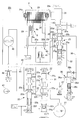
- the lubricating circuit according to the present invention will be described mainly with reference to FIG.
- the hydraulic circuit 20 1 includes an oil pump 21, a primary regulator valve 22, a secondary regulator valve 23 and the lubricating relay valve 25.
- the oil pump 21 may be a mechanical pump that is driven by the engine output shaft 5a and a pump that generates hydraulic pressure by both of the electric pumps.
- the oil pump 21 may be any one of the engine output shaft 5a and the rotor of the electric motor 3.
- One pump driven by the faster rotation may be used, and in any case, a predetermined hydraulic pressure is generated regardless of whether the drive source of the vehicle is the electric motor 3 or the internal combustion engine 5.
- the electric motor 3 schematically shown includes a large-diameter hollow motor, and includes a stator 24 fixed to a case and a rotor 26 that is integrally connected to an input shaft of the automatic transmission.
- the coil end 24a protrudes from both sides of the iron core in the width direction.
- a disengagement (K0) clutch 6 is disposed on the inner diameter side of the rotor 26.
- the K0 clutch 6 is a wet multi-plate clutch, its inner friction plate 6a is connected to the engine output member, and its outer friction plate 6b is connected to the rotor 26 of the electric motor 3 and the input shaft 7 of the automatic transmission 2.
- the engine output member is connected to the engine crankshaft via a torsion spring or the like, and substantially rotates integrally with the engine output shaft, and is hereinafter referred to as an engine output shaft 5a.
- the K0 clutch 6 is controlled to release, slip control, and complete engagement by the hydraulic pressure applied to the hydraulic servo 29.
- the hydraulic servo 29 is supplied with a control pressure (P SLU ) from a linear solenoid valve.
- P SLU control pressure
- the K0 clutch 6 is housed in a clutch chamber 30. Lubricating oil is supplied to the clutch chamber 30 from the import 30a and passes through the multi-plate friction plates 6a and 6b of the K0 clutch 6 and is outported. It is discharged from 30b.
- the primary regulator valve 22 has a spool 22s biased by a spring 22b, and has a feedback port 22c, a line pressure port 22a, a surplus pressure port 22e, and a back pressure port 22f at one end of the spool.
- a control pressure PSLT from a linear solenoid valve controlled based on the slot opening is supplied to the oil chamber 22g in which the spring 22b is disposed.
- Oil from the oil pump 21 is supplied to the feedback port 22c and the line pressure port 22a via a line pressure oil passage 31, and the spool 22s has a feedback pressure of the feedback port 22c and a control pressure of the oil chamber 22g.
- the line pressure port 22a is adjusted to a line pressure corresponding to the slot opening by adjusting the communication ratio between the line pressure port 22a, the surplus pressure port 22e and the back pressure port 22f.
- the surplus pressure from the surplus pressure port 22 e is returned to the oil pump 21, and the back pressure from the back pressure port 22 f communicates with the secondary pressure oil path (pressure regulation oil path) 32.
- the secondary regulator valve 23 has a spool 23s urged by a spring 23b.
- a feedback port 23c, a secondary pressure port 23a, a surplus pressure port 23d, a back pressure port 23e, and the spring 23b are provided at one end of the spool.
- An oil chamber 23f is housed.
- the oil chamber 23f is supplied with a control pressure PSLT from a linear solenoid valve controlled based on the slot opening. Accordingly, the back pressure from the back pressure port 22f of the primary regulator valve 22 is used as the original pressure, and the oil pressure in the secondary pressure oil passage 32 is moved by the spool 23s by the feedback pressure in the feedback port 23c and the control pressure in the oil chamber 23f.
- the communication ratio between the pressure port 23a, the surplus pressure port 23d, and the back pressure port 23e is adjusted to become a secondary pressure.
- the surplus pressure of the surplus pressure port 23d is returned to the oil pump 21, and the back pressure of the back pressure port 23e is supplied to the lubricating oil passage 45 as lubricating oil pressure.
- the lubrication relay valve 25 has a spool 25s urged by a spring 25c, and has a control oil chamber 25d at one end of the spool.
- the control oil chamber 25d includes a solenoid valve for switching on and off.
- the hydraulic pressure from 35 is supplied.
- the lubrication relay valve 25 has an input port 25a communicating with the secondary pressure oil passage 32, an input port 25b to which the modulator pressure from the modulator valve 36 is supplied, a first output port 25g, and a second output.
- a port 25f, a third output port 25i, and a fourth output port 25h are provided.
- the solenoid valve 35 outputs (ON) or shuts off (OFF) the modulator pressure P MOD and guides it to the control oil chamber 25d to switch the lubrication relay valve 25.
- the modulator valve 36 is supplied with line pressure from the line pressure oil passage 31 through a check valve 37 for preventing backflow to the input port 36a, and acts on the feedback pressure of the feedback port 36b acting on one end of the spool 36s and on the other end.
- a predetermined modulator pressure is output from the output port 36d to the modulator oil passage 38 by the spring 36c.
- Lubricating oil from the fourth output port 25h is supplied to the electric motor 3 through the shaft core oil passage 42 formed in the input shaft 7.
- Lubricating oil from the third output port 25i is directly supplied to the stator 24 of the electric motor 3 through a direct oil passage 43 formed in a case or the like.
- the lubricating oil passage 45 from the back pressure port 23e of the secondary regulator valve 23 is led to each lubricating portion 47 of the automatic transmission 2 via an oil cooler 46.
- the lubricating oil passage 45 branches and communicates with the cooler bypass valve 49, and surplus oil to the cooler 46 is directly guided to the lubricating portion 47.
- the hybrid vehicle drive device 1 starts with the electric motor 3 as a drive source at normal times when the remaining battery level (SOC) is not insufficient. That is, the electric motor 3 is in a creep state in which creep torque is generated while the shift lever is in the D (drive) range and the automatic transmission 2 is in the first speed. When the driver depresses the accelerator pedal from this state, the torque of the electric motor 3 generates a torque corresponding to the accelerator opening. The torque of the electric motor 3 is transmitted to the drive wheel 10 via the automatic transmission 2 to start the vehicle. At this time, the K0 clutch 6 is in a disengaged state.
- SOC remaining battery level
- the K0 clutch 6 When the vehicle reaches a predetermined speed, the K0 clutch 6 is connected and the internal combustion engine 5 is started by the torque of the electric motor 3. In a state where the engine 5 is started, the rotation of the engine output shaft 5a is transmitted to the driving wheel 10 via the automatic transmission 2, and the vehicle speed increases to the cruising speed by upshifting the automatic transmission 2. Become. At this time, the electric motor 3 outputs the engine torque so as to assist, generates electric power (regeneration) by the engine torque or vehicle inertia force, or rotates with no load.
- the solenoid valve 35 remains in the OFF state, and the lubrication relay valve 25 is held in the illustrated state (OFF position) in which the spool 25s is moved in accordance with the spring 25c.
- the secondary pressure in the oil passage 32 regulated by the secondary regulator valve 23 is output from the secondary pressure input port 25a of the lubrication relay valve 25 to the second output port 25f.
- the hydraulic pressure from the second output port 25f is reduced by the orifice 39 to become a small flow rate, and is guided from the clutch lubricating oil passage 40 into the clutch chamber 30 via the import 30a.
- the K0 clutch 6 in the clutch chamber 30 is slip-controlled for a short time when the internal combustion engine 5 is started, the K0 clutch 6 is substantially in a disengaged state at the time of starting and is in a fully engaged state after the engine is started. After being lubricated and cooled by the small flow rate, the lubricating oil in the clutch chamber 30 is discharged from the outport 30b. At this time, the lubricating oil does not accumulate in the clutch chamber 30, and the drag torque by the oil can be suppressed to a sufficiently low amount in the released state of the clutch.
- the line pressure of the line pressure oil passage 31 is adjusted to a predetermined pressure by the modulator valve 36 via the check valve 37 and supplied to the modulator pressure input port 25 b of the lubrication relay valve 25 via the modulator oil passage 38. .
- the input port 25 b communicates with the fourth output port 25 h as shown in the figure, and is led to the shaft core oil passage 42.
- the lubricating oil from the shaft oil passage 42 is supplied to the electric motor 3 by the centrifugal force generated by the rotation of the input shaft 7.
- the lubricating oil pressure from the back pressure port 23 e of the secondary regulator valve 23 is supplied to the lubricating portion 47 of the automatic transmission 2 via the lubricating oil passage 45 and the oil cooler 46.
- the hybrid drive device 1 starts using the internal combustion engine 5 as a drive source, and at this time, the K0 clutch 6 functions as a start clutch.
- the internal combustion engine 5 is in a rotating state
- the shift lever is in the D range
- the automatic transmission 2 is in the first speed state.
- the K0 clutch 6 that is the starting clutch is in a disengaged (released) state
- the solenoid valve 35 is in the OFF position
- the lubrication relay valve 25 is In the illustrated state (OFF position), as described above, lubricating oil at a small flow rate is supplied to the clutch chamber 30 from the second output port 25f through the orifice 39.
- the vehicle When the driver releases the brake pedal pressure, the vehicle enters a start standby state, and the start clutch 6 is slip-controlled. That is, the operating pressure supplied to the hydraulic servo 29 becomes the creep pressure, and the start clutch 6 is slip-controlled so as to generate a creep torque. Then, the solenoid valve 35 is switched ON, and the ON pressure of the solenoid valve 35 is supplied to the control oil chamber 25d of the lubrication relay valve 25, and the lubrication relay valve 25 moves downward with its spool 25s against the spring 25c. (ON position).
- the secondary pressure from the secondary pressure oil passage 32 is output from the input port 25a to the first output port 25g, and is guided to the import 30a of the clutch chamber 30 through the clutch lubricating oil passage 40 with the oil amount as it is. .
- the large amount of lubricating oil guided to the import 30a is larger than the amount of lubricating oil discharged from the outport 30b, so that the clutch chamber 30 is filled with lubricating oil, and the clutch 6 has its multi-plate friction plates 6a, Slip control is performed with 6b immersed in the lubricating oil.
- the start standby state is a state in which the driver releases the brake depression pressure, but is not limited thereto, and may be another state such as a state in which the shift lever is switched to the D range.
- the start clutch 6 increases its torque capacity while performing slip control. Increase and start the vehicle.
- the slip control of the starting clutch 6 a large amount of lubricating oil is supplied, and the multi-plate friction plate of the K0 clutch 6 is immersed in a sufficient amount of lubricating oil to suppress heat generation.
- the slip control of the start (K0) clutch 6 is performed when the driver slowly depresses the accelerator pedal and the time until complete engagement is long, or when the creep state continues for a long time due to start on climbing, etc. Even if it becomes longer, the K0 clutch 6 can be prevented from being soaked in a sufficient amount of lubricating oil and reaching a high temperature.
- the secondary oil amount from the back pressure port 22f of the primary regulator valve 22 defined by the oil pump 21 is almost entirely used for lubrication of the K0 clutch 6, and from the lubricating oil passage 45 to the automatic transmission device 2 There is no or very little lubricating oil supplied to the lubrication part 47.
- the input port 25b from the modulator pressure oil passage 38 communicates with the third output port 25i. Oil from the output port 25 i is directly supplied from the oil passage 43 to the stator 24 of the electric motor 3. Thereby, even if the input shaft 7 of the automatic transmission 2 is stopped or rotated at a very low speed, the electric motor 3 is directly supplied with the lubricating oil from the modulator pressure oil passage 38 and cooled.
- the starting clutch K0 clutch 6 When the starting clutch K0 clutch 6 is completely engaged, the output torque of the internal combustion engine 5 is transmitted to the input shaft 7 of the automatic transmission 2 as it is, and the automatic transmission 2 is appropriately upshifted, so that the vehicle is cruising speed. Drive on. At this time, generally, since the remaining battery level is insufficient, the electric motor 3 functions as a generator and is charged by the internal combustion engine.
- the solenoid valve 35 When the K0 clutch 6 is completely engaged, the solenoid valve 35 is turned off and the lubrication relay valve 25 is switched to the state shown in the figure (OFF position). In this state, the secondary pressure input port 25 a communicates with the second output port 25 f, and a small amount of lubricating oil is supplied to the clutch chamber 30 via the orifice 39. Due to the restriction of the orifice 39, the secondary pressure of the secondary pressure oil passage 32 is increased, and the feedback pressure of the feedback port 23c of the secondary regulator valve 23 is also increased. Thereby, the spool 23s moves against the spring 23b, and the communication ratio between the secondary pressure port 23a and the back pressure port 23e increases.
- the specified original pressure from the back pressure port 22f of the primary regulator valve 22 is reduced in the flow rate supplied to the secondary pressure oil passage 32 as the secondary pressure, and the back pressure port 23e to the lubricating oil passage 45 is reduced.
- the flow rate ratio is increased.
- the automatic transmission 2 is in a predetermined high-speed rotation state, and the lubricating oil in the lubricating oil passage 45 having the large flow rate is applied to each of the automatic transmissions. It is supplied to the lubrication part 47.
- a relief valve 41 is provided branching to the clutch lubricating oil passage 40. As described above, when the oil pressure in the lubricating oil passage 40, and hence the clutch chamber 30, increases by a predetermined value or more, the relief valve 41 is Release to prevent the hydraulic pressure from rising above the predetermined value.
- the solenoid valve 35 that is turned on in response to the slip control of the K0 clutch 6 and is turned off in other states (released and completely engaged) is controlled by the input shaft rotational speed sensor 12 and the engine output. It is controlled by a signal from the vehicle control device 10 based on the shaft rotational speed sensor 11 or based on the throttle opening sensor and the foot brake ON / OFF switch.
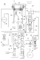
- FIG. 3 shows an embodiment in which the position of the orifice 39 interposed in the clutch lubricating oil passage 40 is changed. That is, the hydraulic circuit 20 2 'provided, ⁇ Tsuyuro 40' communicating oil passage 40 for communicating the secondary pressure oil passage 32 and the clutch lubricating oil passage 40 directly interposed the orifice 39. Accordingly, the second output port 25f of the lubrication relay valve 25 that is necessary in FIG.
- the lubrication relay valve 25 When the K0 clutch 6 is not in the slip control state (released, fully engaged), the lubrication relay valve 25 is in the OFF position by the solenoid valve 35 and is closed to the secondary pressure input port 25a. In this state, a small amount of oil is supplied from the secondary pressure oil passage 32 directly to the lubricating oil passage 40 through the orifice 39, and the K0 clutch 6 is lubricated. At this time, the hydraulic pressure in the secondary pressure oil passage 32 increases, the high pressure acts on the feedback port 23c, the communication ratio between the secondary pressure port 23a and the back pressure port 23e increases, and a relatively large amount of oil becomes lubricating oil. The oil is supplied to the passage 45 and lubricates the lubricating portion 47 of the automatic transmission.
- the lubrication relay valve 25 In a state in which the K0 clutch 6 is slip-controlled, the lubrication relay valve 25 is switched to the ON position by the solenoid valve 35, the secondary pressure input port 25a communicates with the first output port 25g, and the oil in the secondary pressure oil path 32 flows.
- the clutch lubricating oil passage 40 is directly supplied without passing through the orifice.
- the K0 clutch 6 in the slip control state is lubricated and cooled by the large flow amount of oil while the clutch chamber 30 is filled.
- the secondary pressure oil passage 32 is in a low pressure state close to release, and the supply ratio from the back pressure port 23e to the lubricating oil passage 45 by the secondary regulator valve 23 is significantly reduced.
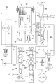
- FIG. 4 shows an embodiment in which line pressure is supplied as the original pressure of the input port 25a of the lubrication relay valve 25.
- the hydraulic circuit 20 3 the line pressure oil passage 31 communicating with the line pressure port 22a of the primary regulator valve 22, communicates with the input port 25a of the lubricating relay valve 25.
- the lubrication relay valve 25 When the K0 clutch 6 is disengaged or completely engaged, the lubrication relay valve 25 is in the illustrated OFF position by the solenoid valve 35. In this state, the line pressure regulated by the primary regulator valve 22 is supplied to the second output port 25f via the line pressure oil passage (pressure regulation oil passage) 31 and the input port 25a. Then, a small amount of oil throttled by the orifice 39 is supplied to the K0 clutch 6 in the clutch chamber 30 through the clutch lubricating oil passage 40.
- the back pressure (secondary pressure) from the back pressure port 22f also increases, and the feedback pressure acting on the feedback port 23c of the secondary regulator valve 23 also increases.
- the communication ratio between the secondary pressure port 23a and the back pressure port 23e of the valve is increased, and the amount of lubricating oil supplied from the back pressure port to the lubricating oil passage 45 is increased. That is, when the K0 clutch 6 is in the non-slip state, the amount of lubricating oil in the K0 clutch is reduced, and the amount of lubricating oil to the automatic transmission 2 increases accordingly.
- the lubrication relay valve 25 is switched to the ON position by the solenoid valve 35.
- the line pressure oil passage 31 directly communicates with the clutch lubricating oil passage 40 via the input port 25a and the first output port 25g, and a large amount of oil from the line pressure oil passage 31 directly enters the clutch chamber 30.
- the K0 clutch 6 is sufficiently lubricated and cooled.
- the hydraulic pressure of the line pressure oil passage 31 is reduced by that amount, the feedback pressure of the feedback port 22c of the primary regulator valve 22 is also reduced, and the communication ratio between the line pressure port 22a and the back pressure port 22f is reduced.
- the amount of oil supplied from the back pressure port 22f to the secondary pressure oil passage decreases.
- the feedback pressure of the feedback port 23c of the secondary regulator valve 23 is also reduced, and the amount of oil guided from the back pressure port 23e to the lubricating oil passage 45 is also reduced. That is, during the slip control of the K0 clutch 6, most of the specified oil amount from the oil pump 21 is used for lubrication and cooling of the K0 clutch 6 and used as lubricating oil for the automatic transmission 2. Is regulated.
- the present invention has been applied to the hybrid vehicle drive device 1 and described when starting with the internal combustion engine.
- the present invention is not limited to this, and the slip control of the K0 clutch 6 when starting the engine with the electric motor 3 is started. Can be applied as well.
- the present invention is not limited to the hybrid vehicle drive device, and can be similarly applied to a vehicle drive device including only an internal combustion engine as a drive source, having a start clutch.
- the present invention can be similarly applied to an automatic transmission device including a torque converter having a lock-up clutch and using the lock-up clutch as a starting clutch.
- the present invention is used for a vehicle such as an automobile equipped with a drive device, particularly a one-motor type hybrid drive device.
Abstract
Description
元圧(22f)(21)からの調圧油路(32)(31)に連通する調圧ポート(23a)(22a)及びフィードバックポート(23c)(22c)と、背面圧油路(45)(32)に連通する背面圧ポート(23e)(22f)と、を有し、前記調圧ポートと前記背面圧ポートとの連通割合を調整して、前記調圧油路(32)(31)の油圧を調圧するレギュレータバルブ(23)(22)と、
前記調圧油路(32)(31)に連通する入力ポート(25a)と出力ポート(25g)とを有し、前記入力ポートと前記出力ポートとを連通又は遮断位置に切換える潤滑リレーバルブ(25)と、
前記調圧油路(32)(31)とオリフィス(39)を介して連通すると共に前記出力ポート(25g)に連通し、前記クラッチ(6)に潤滑油を供給するクラッチ潤滑油路(40)と、を備え、
前記潤滑リレーバルブ(25)が連通した位置(ON位置)にあっては、前記調圧油路(32)(31)からのオイルを前記入力ポート(25a)、前記出力ポート(25g)及び前記クラッチ潤滑油路(40)を介して前記クラッチ(6)に供給すると共に、前記フィードバックポート(23c)(22c)のフィードバック圧を低下し、前記調圧ポート(23a)(22a)と前記背面圧ポート(23e)(22f)との連通割合を減少して、前記背面圧油路(45)(32)から前記自動変速装置(2)の潤滑部(47)に供給される潤滑油量を減少し、
前記潤滑リレーバルブ(25)が遮断した位置(OFF位置)にあっては、前記調圧油路(32)(31)からのオイルを前記オリフィス(39)及び前記クラッチ潤滑油路(40)を介して前記クラッチ(6)に供給すると共に、前記フィードバックポート(23c)(22c)のフィードバック圧を高めて、前記調圧ポート(23a)(22a)と前記背面圧ポート(23e)(22f)との連通割合を増加して、前記背面圧油路(45)(32)から前記自動変速装置(2)の潤滑部(47)に供給される潤滑油を増加する、
ことを特徴とする車両用駆動装置にある。
前記調圧油路は、前記セカンダリレギュレータバルブ(23)の調圧ポートであるセカンダリ圧ポート(23a)に連通するセカンダリ圧油路(32)であり、
前記背面圧油路は、前記セカンダリレギュレータバルブ(23)の背面圧ポート(23e)から延びている潤滑油路(45)である。
該第2の出力ポート(25f)が前記オリフィス(39)を介して前記クラッチ潤滑油路(40)に連通してなる。
該アウトポートからの排出油量が、前記潤滑リレーバルブ(25)の前記出力ポート(25g)を介して直接供給される供給量より少なく、かつ前記オリフィス(39)を介して供給される供給量より多い。
前記クラッチは、前記回転電機(3)のロータと前記エンジン出力部材(5a)とを接続又は切断する切離しクラッチ(6)である。
前記モジュレータ圧入力ポート(25b)を、前記潤滑リレーバルブ(25)の連通時(ON)に前記第3の出力ポート(25i)に連通し、前記潤滑リレーバルブの遮断時(OFF)に前記第4の出力ポート(25h)に連通してなる。
2 自動変速装置
3 回転電機(電気モータ)
5 エンジン
5a エンジン出力部材(出力軸)
6 (切離し、発進)クラッチ
21 元圧(オイルポンプ)
22 (プライマリ)レギュレータバルブ
22a 調圧(ライン圧)ポート
22c フィードバックポート
22f 背面圧ポート
23 (セカンダリ)レギュレータバルブ
23a 調圧(セカンダリ圧)ポート
23c フィードバックポート
23e 背面圧ポート
25 潤滑リレーバルブ
25a (調圧)入力ポート
25b モジュレータ圧入力ポート
25g (第1の)出力ポート
25f 第2の出力ポート
25i 第3の出力ポート
25h 第4の出力ポート
26 ロータ
30 クラッチ室
30a インポート
30b アウトポート
31 調圧(ライン圧)油路
32 調圧(セカンダリ圧)油路
39 オリフィス
40 クラッチ潤滑油路
40’ 連通油路
42 軸芯油路
43 直接油路
45 背面圧(潤滑)油路
47 潤滑部
Claims (8)
- エンジン出力部材と自動変速装置との間にクラッチを介在して、車両発進に際して前記クラッチをスリップ制御する発進クラッチとして用いてなる、車両用駆動装置において、
元圧からの調圧油路に連通する調圧ポート及びフィードバックポートと、背面圧油路に連通する背面圧ポートと、を有し、前記調圧ポートと前記背面圧ポートとの連通割合を調整して、前記調圧油路の油圧を調圧するレギュレータバルブと、
前記調圧油路に連通する入力ポートと出力ポートとを有し、前記入力ポートと前記出力ポートとを連通又は遮断位置に切換える潤滑リレーバルブと、
前記調圧油路とオリフィスを介して連通すると共に前記出力ポートに連通し、前記クラッチに潤滑油を供給するクラッチ潤滑油路と、を備え、
前記潤滑リレーバルブが連通した位置にあっては、前記調圧油路からのオイルを前記入力ポート、前記出力ポート及び前記クラッチ潤滑油路を介して前記クラッチに供給すると共に、前記フィードバックポートのフィードバック圧を低下し、前記調圧ポートと前記背面圧ポートとの連通割合を減少して、前記背面圧油路から前記自動変速装置の潤滑部に供給される潤滑油量を減少し、
前記潤滑リレーバルブが遮断した位置にあっては、前記調圧油路からのオイルを前記オリフィス及び前記クラッチ潤滑油路を介して前記クラッチに供給すると共に、前記フィードバックポートのフィードバック圧を高めて、前記調圧ポートと前記背面圧ポートとの連通割合を増加して、前記背面圧油路から前記自動変速装置の潤滑部に供給される潤滑油を増加する、
ことを特徴とする車両用駆動装置。 - 前記レギュレータバルブは、セカンダリレギュレータバルブであり、
前記調圧油路は、前記セカンダリレギュレータバルブの調圧ポートであるセカンダリ圧ポートに連通するセカンダリ圧油路であり、
前記背面圧油路は、前記セカンダリレギュレータバルブの背面圧ポートから延びている潤滑油路である、
請求項1記載の車両用駆動装置。 - 前記潤滑リレーバルブは、前記出力ポートである第1の出力ポートの外に第2の出力ポートを有し、
該第2の出力ポートが前記オリフィスを介して前記クラッチ潤滑油路に連通してなる、
請求項1又は2記載の車両用駆動装置。 - 前記調圧油路と前記クラッチ潤滑油路を直接連通する連通油路を設け、該連通油路に前記オリフィスを介在してなる、
請求項1又は2記載の車両用駆動装置。 - 前記クラッチ潤滑油路から分岐して、所定高圧を逃がすリリーフバルブを設けた、
請求項1ないし4のいずれか記載の車両用駆動装置。 - 前記クラッチは、クラッチ室に収納された多板湿式クラッチからなり、該クラッチ室に、インポートを介して前記クラッチ潤滑油路からの潤滑油が供給されると共に、アウトポートを介して該潤滑油が排出され、
該アウトポートからの排出油量が、前記潤滑リレーバルブの前記出力ポートを介して直接供給される供給量より少なく、かつ前記オリフィスを介して供給される供給量より多い、
請求項1ないし5のいずれか記載の車両用駆動装置。 - 回転電機を備え、該回転電機のロータが前記自動変速装置の入力部材に連結し、前記車両用駆動装置がハイブリッド車両用駆動装置であり、
前記クラッチは、前記回転電機のロータと前記エンジン出力部材とを接続又は切断する切離しクラッチである、
請求項1ないし6のいずれか記載の車両用駆動装置。 - 前記潤滑リレーバルブは、前記元圧を所定圧に減圧したモジュレータ圧が供給されるモジュレータ圧入力ポートと、前記回転電機に直接潤滑油を供給する第3の出力ポートと、前記自動変速装置の軸芯油路を介して前記回転電機に連通する第4の出力ポートと、を有し、
前記モジュレータ圧入力ポートを、前記潤滑リレーバルブの連通時に前記第3の出力ポートに連通し、前記潤滑リレーバルブの遮断時に前記第4の出力ポートに連通してなる、
請求項7記載の車両用駆動装置。
Priority Applications (3)
| Application Number | Priority Date | Filing Date | Title |
|---|---|---|---|
| US14/367,008 US20140349811A1 (en) | 2012-02-27 | 2013-02-27 | Vehicle driving system |
| CN201380004476.6A CN104011417A (zh) | 2012-02-27 | 2013-02-27 | 车辆用驱动装置 |
| DE112013000340.6T DE112013000340T5 (de) | 2012-02-27 | 2013-02-27 | Fahrzeugantriebssystem |
Applications Claiming Priority (2)
| Application Number | Priority Date | Filing Date | Title |
|---|---|---|---|
| JP2012-040328 | 2012-02-27 | ||
| JP2012040328A JP5652414B2 (ja) | 2012-02-27 | 2012-02-27 | 車両用駆動装置 |
Publications (1)
| Publication Number | Publication Date |
|---|---|
| WO2013129455A1 true WO2013129455A1 (ja) | 2013-09-06 |
Family
ID=49082650
Family Applications (1)
| Application Number | Title | Priority Date | Filing Date |
|---|---|---|---|
| PCT/JP2013/055083 WO2013129455A1 (ja) | 2012-02-27 | 2013-02-27 | 車両用駆動装置 |
Country Status (5)
| Country | Link |
|---|---|
| US (1) | US20140349811A1 (ja) |
| JP (1) | JP5652414B2 (ja) |
| CN (1) | CN104011417A (ja) |
| DE (1) | DE112013000340T5 (ja) |
| WO (1) | WO2013129455A1 (ja) |
Families Citing this family (15)
| Publication number | Priority date | Publication date | Assignee | Title |
|---|---|---|---|---|
| KR20160099688A (ko) * | 2013-12-17 | 2016-08-22 | 혼다 기켄 고교 가부시키가이샤 | 차량 |
| JP6269624B2 (ja) * | 2015-09-08 | 2018-01-31 | トヨタ自動車株式会社 | ハイブリッド車両の制御装置 |
| US9856931B2 (en) * | 2016-02-29 | 2018-01-02 | GM Global Technology Operations LLC | Hydraulic control system |
| DE102016014672A1 (de) * | 2016-12-09 | 2018-06-14 | Daimler Ag | Hybrid-Triebkopf für ein Kraftfahrzeug |
| DE102017203541B3 (de) | 2017-03-03 | 2018-06-21 | Audi Ag | Antriebsvorrichtung und Kraftfahrzeug mit einer Antriebsvorrichtung |
| DE102017213901A1 (de) * | 2017-08-09 | 2019-02-14 | Volkswagen Aktiengesellschaft | Steuereinheit für ein automatisiertes Schaltgetriebe und zumindest eine Kupplung |
| CN111183569B (zh) * | 2017-09-27 | 2023-06-02 | 尼亚布科知识产权控股有限责任公司 | 润滑剂支撑的电动机 |
| JP7050482B2 (ja) * | 2017-12-25 | 2022-04-08 | 株式会社Subaru | オイル昇温装置 |
| DE102018214332A1 (de) * | 2018-08-24 | 2020-02-27 | Zf Friedrichshafen Ag | Hydrauliksystem zum Schalten einer Fahrzeugkupplung |
| KR102540557B1 (ko) * | 2018-12-10 | 2023-06-07 | 현대자동차주식회사 | 하이브리드 차량의 윤활조절밸브 고착 진단 방법 |
| DE102019207254A1 (de) | 2019-05-17 | 2020-11-19 | Zf Friedrichshafen Ag | Verfahren und Steuergerät zum Betreiben eines Antriebsstrangs eines Kraftfahrzeugs |
| US11585429B2 (en) * | 2019-09-25 | 2023-02-21 | Neapco Intellectual Property Holdings, Llc | Lubricant supply system and methods for a lubricant supported electric motor |
| CN112879463B (zh) * | 2019-11-29 | 2022-09-27 | 上海汽车集团股份有限公司 | 混动变速箱电液控制系统及混动变速箱 |
| CN114761709B (zh) * | 2019-12-06 | 2023-08-01 | 加特可株式会社 | 变速器及润滑油压控制阀的控制方法 |
| CN112013039B (zh) * | 2020-08-17 | 2021-12-28 | 杭州前进齿轮箱集团股份有限公司 | 离合器及其端盖 |
Citations (9)
| Publication number | Priority date | Publication date | Assignee | Title |
|---|---|---|---|---|
| JPH0160028U (ja) * | 1987-10-13 | 1989-04-17 | ||
| JPH0181126U (ja) * | 1987-11-17 | 1989-05-31 | ||
| JPH07127661A (ja) * | 1993-11-02 | 1995-05-16 | Hino Motors Ltd | 油圧制御式クラッチの冷却装置 |
| US5518098A (en) * | 1994-12-01 | 1996-05-21 | New Holland North America, Inc. | Dual flow control for hydraulic clutch |
| JP2005106149A (ja) * | 2003-09-30 | 2005-04-21 | Jatco Ltd | ハイブリッド車両の制御装置 |
| JP2007303624A (ja) * | 2006-05-15 | 2007-11-22 | Mazda Motor Corp | 自動変速機 |
| WO2012114806A1 (ja) * | 2011-02-23 | 2012-08-30 | アイシン・エィ・ダブリュ株式会社 | 自動変速装置の摩擦板潤滑装置 |
| JP2012171372A (ja) * | 2011-02-17 | 2012-09-10 | Aisin Aw Co Ltd | 車両用駆動装置 |
| JP2012180867A (ja) * | 2011-02-28 | 2012-09-20 | Aisin Aw Co Ltd | 自動変速装置の潤滑装置 |
Family Cites Families (4)
| Publication number | Priority date | Publication date | Assignee | Title |
|---|---|---|---|---|
| US5802490A (en) * | 1996-02-20 | 1998-09-01 | Ford Global Technologies, Inc. | Torque converter regulator and clutch lockout system for an automotive vehicle |
| JP2007113640A (ja) * | 2005-10-19 | 2007-05-10 | Toyota Motor Corp | 駆動装置 |
| JP2009243640A (ja) * | 2008-03-31 | 2009-10-22 | Aisin Aw Co Ltd | 発進装置の油圧制御装置 |
| JP5195471B2 (ja) * | 2009-01-30 | 2013-05-08 | アイシン・エィ・ダブリュ株式会社 | 動力伝達装置およびこれを搭載する車両 |
-
2012
- 2012-02-27 JP JP2012040328A patent/JP5652414B2/ja not_active Expired - Fee Related
-
2013
- 2013-02-27 DE DE112013000340.6T patent/DE112013000340T5/de not_active Withdrawn
- 2013-02-27 CN CN201380004476.6A patent/CN104011417A/zh active Pending
- 2013-02-27 WO PCT/JP2013/055083 patent/WO2013129455A1/ja active Application Filing
- 2013-02-27 US US14/367,008 patent/US20140349811A1/en not_active Abandoned
Patent Citations (9)
| Publication number | Priority date | Publication date | Assignee | Title |
|---|---|---|---|---|
| JPH0160028U (ja) * | 1987-10-13 | 1989-04-17 | ||
| JPH0181126U (ja) * | 1987-11-17 | 1989-05-31 | ||
| JPH07127661A (ja) * | 1993-11-02 | 1995-05-16 | Hino Motors Ltd | 油圧制御式クラッチの冷却装置 |
| US5518098A (en) * | 1994-12-01 | 1996-05-21 | New Holland North America, Inc. | Dual flow control for hydraulic clutch |
| JP2005106149A (ja) * | 2003-09-30 | 2005-04-21 | Jatco Ltd | ハイブリッド車両の制御装置 |
| JP2007303624A (ja) * | 2006-05-15 | 2007-11-22 | Mazda Motor Corp | 自動変速機 |
| JP2012171372A (ja) * | 2011-02-17 | 2012-09-10 | Aisin Aw Co Ltd | 車両用駆動装置 |
| WO2012114806A1 (ja) * | 2011-02-23 | 2012-08-30 | アイシン・エィ・ダブリュ株式会社 | 自動変速装置の摩擦板潤滑装置 |
| JP2012180867A (ja) * | 2011-02-28 | 2012-09-20 | Aisin Aw Co Ltd | 自動変速装置の潤滑装置 |
Also Published As
| Publication number | Publication date |
|---|---|
| JP2013174335A (ja) | 2013-09-05 |
| DE112013000340T5 (de) | 2014-08-28 |
| US20140349811A1 (en) | 2014-11-27 |
| JP5652414B2 (ja) | 2015-01-14 |
| CN104011417A (zh) | 2014-08-27 |
Similar Documents
| Publication | Publication Date | Title |
|---|---|---|
| JP5652414B2 (ja) | 車両用駆動装置 | |
| JP6036277B2 (ja) | 車両用伝動装置 | |
| US7815026B2 (en) | Torque converter impeller clutch control | |
| US8857188B2 (en) | Hybrid drive device | |
| JP6107930B2 (ja) | 車両の油圧制御装置 | |
| CN110242744B (zh) | 变速器和液压控制系统 | |
| CN110431332B (zh) | 油供给装置 | |
| JP2010151240A (ja) | 油圧制御装置 | |
| US9140312B2 (en) | Hydraulic control device for hybrid drive device | |
| JP2008208931A (ja) | 油圧供給装置 | |
| JP5708544B2 (ja) | 車両用駆動装置 | |
| US8342997B2 (en) | Hydraulic control device for automatic transmission | |
| US6508741B1 (en) | Hydraulic control system for automatic transmissions | |
| JP4385752B2 (ja) | 変速機の潤滑装置 | |
| JP5321421B2 (ja) | 発進装置の油圧制御装置 | |
| JP6139302B2 (ja) | 車両用ロックアップクラッチの制御装置 | |
| JPWO2020158869A1 (ja) | 車両用駆動装置 | |
| JP2014206235A (ja) | ベルト式無段変速機の油圧制御装置 | |
| JP2019043189A (ja) | 車両 | |
| US11543026B2 (en) | Control device for automatic transmission | |
| JP2009103221A (ja) | 油圧制御装置及びそれを用いた車両用駆動装置 | |
| US20210102620A1 (en) | Control device for automatic transmission | |
| JP5666385B2 (ja) | ハイブリッド駆動装置 | |
| WO2012098669A1 (ja) | ハイブリッド車両の駆動装置 | |
| KR20220159156A (ko) | 하이브리드 차량의 eop 제어방법 |
Legal Events
| Date | Code | Title | Description |
|---|---|---|---|
| 121 | Ep: the epo has been informed by wipo that ep was designated in this application |
Ref document number: 13755893 Country of ref document: EP Kind code of ref document: A1 |
|
| WWE | Wipo information: entry into national phase |
Ref document number: 14367008 Country of ref document: US |
|
| WWE | Wipo information: entry into national phase |
Ref document number: 1120130003406 Country of ref document: DE Ref document number: 112013000340 Country of ref document: DE |
|
| 122 | Ep: pct application non-entry in european phase |
Ref document number: 13755893 Country of ref document: EP Kind code of ref document: A1 |