WO2013128856A1 - ズーム光学系 - Google Patents
ズーム光学系 Download PDFInfo
- Publication number
- WO2013128856A1 WO2013128856A1 PCT/JP2013/000984 JP2013000984W WO2013128856A1 WO 2013128856 A1 WO2013128856 A1 WO 2013128856A1 JP 2013000984 W JP2013000984 W JP 2013000984W WO 2013128856 A1 WO2013128856 A1 WO 2013128856A1
- Authority
- WO
- WIPO (PCT)
- Prior art keywords
- lens
- lens group
- optical system
- diffractive optical
- optical element
- Prior art date
Links
Images


Classifications
-
- G—PHYSICS
- G02—OPTICS
- G02B—OPTICAL ELEMENTS, SYSTEMS OR APPARATUS
- G02B15/00—Optical objectives with means for varying the magnification
- G02B15/14—Optical objectives with means for varying the magnification by axial movement of one or more lenses or groups of lenses relative to the image plane for continuously varying the equivalent focal length of the objective
- G02B15/16—Optical objectives with means for varying the magnification by axial movement of one or more lenses or groups of lenses relative to the image plane for continuously varying the equivalent focal length of the objective with interdependent non-linearly related movements between one lens or lens group, and another lens or lens group
- G02B15/177—Optical objectives with means for varying the magnification by axial movement of one or more lenses or groups of lenses relative to the image plane for continuously varying the equivalent focal length of the objective with interdependent non-linearly related movements between one lens or lens group, and another lens or lens group having a negative front lens or group of lenses
-
- G—PHYSICS
- G02—OPTICS
- G02B—OPTICAL ELEMENTS, SYSTEMS OR APPARATUS
- G02B13/00—Optical objectives specially designed for the purposes specified below
- G02B13/04—Reversed telephoto objectives
-
- G—PHYSICS
- G02—OPTICS
- G02B—OPTICAL ELEMENTS, SYSTEMS OR APPARATUS
- G02B13/00—Optical objectives specially designed for the purposes specified below
- G02B13/18—Optical objectives specially designed for the purposes specified below with lenses having one or more non-spherical faces, e.g. for reducing geometrical aberration
-
- G—PHYSICS
- G02—OPTICS
- G02B—OPTICAL ELEMENTS, SYSTEMS OR APPARATUS
- G02B15/00—Optical objectives with means for varying the magnification
- G02B15/14—Optical objectives with means for varying the magnification by axial movement of one or more lenses or groups of lenses relative to the image plane for continuously varying the equivalent focal length of the objective
- G02B15/145—Optical objectives with means for varying the magnification by axial movement of one or more lenses or groups of lenses relative to the image plane for continuously varying the equivalent focal length of the objective having five groups only
- G02B15/1455—Optical objectives with means for varying the magnification by axial movement of one or more lenses or groups of lenses relative to the image plane for continuously varying the equivalent focal length of the objective having five groups only the first group being negative
- G02B15/145519—Optical objectives with means for varying the magnification by axial movement of one or more lenses or groups of lenses relative to the image plane for continuously varying the equivalent focal length of the objective having five groups only the first group being negative arranged -+--+
-
- G—PHYSICS
- G02—OPTICS
- G02B—OPTICAL ELEMENTS, SYSTEMS OR APPARATUS
- G02B15/00—Optical objectives with means for varying the magnification
- G02B15/14—Optical objectives with means for varying the magnification by axial movement of one or more lenses or groups of lenses relative to the image plane for continuously varying the equivalent focal length of the objective
- G02B15/145—Optical objectives with means for varying the magnification by axial movement of one or more lenses or groups of lenses relative to the image plane for continuously varying the equivalent focal length of the objective having five groups only
- G02B15/1455—Optical objectives with means for varying the magnification by axial movement of one or more lenses or groups of lenses relative to the image plane for continuously varying the equivalent focal length of the objective having five groups only the first group being negative
- G02B15/145527—Optical objectives with means for varying the magnification by axial movement of one or more lenses or groups of lenses relative to the image plane for continuously varying the equivalent focal length of the objective having five groups only the first group being negative arranged -+-++
-
- G—PHYSICS
- G02—OPTICS
- G02B—OPTICAL ELEMENTS, SYSTEMS OR APPARATUS
- G02B15/00—Optical objectives with means for varying the magnification
- G02B15/14—Optical objectives with means for varying the magnification by axial movement of one or more lenses or groups of lenses relative to the image plane for continuously varying the equivalent focal length of the objective
- G02B15/15—Optical objectives with means for varying the magnification by axial movement of one or more lenses or groups of lenses relative to the image plane for continuously varying the equivalent focal length of the objective compensation by means of only one movement or by means of only linearly related movements, e.g. optical compensation
-
- G—PHYSICS
- G02—OPTICS
- G02B—OPTICAL ELEMENTS, SYSTEMS OR APPARATUS
- G02B27/00—Optical systems or apparatus not provided for by any of the groups G02B1/00 - G02B26/00, G02B30/00
- G02B27/42—Diffraction optics, i.e. systems including a diffractive element being designed for providing a diffractive effect
- G02B27/4205—Diffraction optics, i.e. systems including a diffractive element being designed for providing a diffractive effect having a diffractive optical element [DOE] contributing to image formation, e.g. whereby modulation transfer function MTF or optical aberrations are relevant
- G02B27/4211—Diffraction optics, i.e. systems including a diffractive element being designed for providing a diffractive effect having a diffractive optical element [DOE] contributing to image formation, e.g. whereby modulation transfer function MTF or optical aberrations are relevant correcting chromatic aberrations
Definitions
- the present invention relates to a zoom optical system using a diffractive optical element.
- an optical system such as a digital camera or a video camera has a short total lens length (total optical length, that is, the length from the lens surface (first surface) closest to the object side to the image plane), and the entire optical system is small. Is desired.
- total optical length that is, the length from the lens surface (first surface) closest to the object side to the image plane
- various aberrations including chromatic aberration increase, and the optical performance tends to deteriorate.
- Even if a diffractive optical element is simply provided in such an optical system it is difficult to satisfactorily correct chromatic aberration over the entire zoom range unless the arrangement position and refractive power are set appropriately. If the diffractive optical element is used inappropriately, chromatic aberration correction is insufficient. Further, when the refractive power of the diffractive optical element increases, the grating pitch of the diffractive optical element becomes finer, making it difficult to manufacture and the productivity deteriorates.
- the present invention has been made in view of such a problem.By effectively using a diffractive optical element, the present invention is small and corrects various aberrations including chromatic aberration over the entire zoom range.
- An object of the present invention is to provide a zoom optical system having high optical performance.
- the first lens group having negative refractive power and other lens groups arranged in order from the object side, and other lens groups there is provided a zoom optical system in which a mutual distance between lens groups is changed.
- the first lens group is disposed closest to the object side, and is disposed closer to the image side than the first negative lens and a first negative lens having a diffractive optical element on the image side lens surface.
- the glass material used for the positive lens satisfies the following conditional expression.
- ⁇ 1p Abbe number based on the d-line of the glass material used for the positive lens of the first lens group
- the Abbe number ⁇ d and the partial dispersion ratio ( ⁇ g, F) of the glass type A and the glass type B are the following values.
- a zoom optical system that is small in size, excellently corrects various aberrations including chromatic aberration over the entire zoom range, and has high optical performance is provided. can do.
- FIG. 3 is a cross-sectional view of the zoom optical system according to the first example in the wide-angle end state and a zoom trajectory from the wide-angle end state (W) to the telephoto end state (T).
- FIG. 6 is a longitudinal aberration diagram at an imaging distance infinite in the wide-angle end state of the zoom optical system according to Example 1;
- FIG. 6 is a longitudinal aberration diagram at an imaging distance infinite in the telephoto end state of the zoom optical system according to Example 1;
- FIG. 6 is a structural cross-sectional view of a zoom optical system according to Example 2 in the wide-angle end state and a zoom trajectory from the wide-angle end state (W) to the telephoto end state (T).
- FIG. 3 is a cross-sectional view of the zoom optical system according to the first example in the wide-angle end state and a zoom trajectory from the wide-angle end state (W) to the telephoto end state (T).
- FIG. 6 is a longitudinal aberration diagram at an imaging distance infinite in the wide-angle
- FIG. 6 is a longitudinal aberration diagram at an imaging distance infinite in the wide-angle end state of the zoom optical system according to Example 2;
- FIG. 12 is a longitudinal aberration diagram at an imaging distance infinite in the telephoto end state of the zoom optical system according to Example 2;
- FIG. 10 is a structural cross-sectional view of a zoom optical system according to Example 3 in the wide-angle end state and a zoom trajectory from the wide-angle end state (W) to the telephoto end state (T).
- FIG. 10 is a longitudinal aberration diagram at an imaging distance infinite in the wide-angle end state of the zoom optical system according to Example 3;
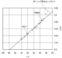
- FIG. 12 is a longitudinal aberration diagram at an imaging distance infinite in the telephoto end state of the zoom optical system according to Example 3; It is a graph for explaining the definition of anomalous dispersion glass, with the Abbe number ⁇ d based on the d-line on the horizontal axis and the partial dispersion ratio ( ⁇ g, F) on the vertical axis.
- 1 is a schematic cross-sectional view illustrating a configuration of a digital single-lens reflex camera (imaging device) using a zoom optical system according to an embodiment.
- the diffractive optical element PF used in the zoom optical system according to the present embodiment is a first diffractive element in which two diffractive element elements made of different optical materials, specifically, a plurality of grating grooves are formed.
- a first diffractive optical element PF1 having an optical surface; and a second diffractive optical element PF2 having a second diffractive optical surface on which a plurality of grating grooves are formed.
- the second diffractive optical element PF2 is disposed so that the first diffractive optical surface and the second diffractive optical surface face each other, and the first diffractive optical surface and the second diffractive optical surface are diffractive optical surface C.
- contact multilayer diffractive optical elements PF which are in close contact with each other.
- the zoom optical system ZL includes a first lens group G1 having a negative refractive power and a second lens group G2 having a positive refractive power, which are arranged in order from the object side.
- the distance between the lens groups changes upon zooming, and the first lens group G1 has at least one contact multilayer diffractive optical element PF.
- the zoom optical system ZL can be miniaturized by changing the mutual distance between the lens groups G1 to G5. Further, the chromatic aberration is effectively corrected by disposing the contact multilayer diffractive optical element PF in the first lens group G1 in which the longitudinal chromatic aberration is largely generated.
- the chromatic aberration is corrected well over the entire zoom range by disposing the multi-contact diffractive optical element PF in the first lens group G1.
- the first lens group G1 includes a first negative lens L11, a second negative lens L12, and a positive lens L13 arranged in order from the object side.
- the first negative lens L11 has a convex surface on the object side.
- the second negative lens L12 has a biconcave lens shape, and the positive lens L13 has a meniscus shape with a convex surface facing the object side.
- the multi-contact diffractive optical element PF is disposed on the image side lens surface (second surface) of the first negative lens L11, and it is desirable that this surface be an aspherical surface. According to this configuration, good aberration correction can be performed over the entire zoom range.
- ⁇ 1p Abbe number based on the d-line of the glass material used for the positive lens L13 of the first lens group G1
- a straight line connecting Ohara Glass Type Name NSL7
- Glass Type B Ohara Glass Type Name PBM2
- ⁇ d is an Abbe number with respect to the d-line
- ng, nF, and nC are refractive indexes of the Fraunhofer line with respect to the g-line, F-line, and C-line, respectively.
- ⁇ 1dave Among the lenses constituting the first lens group G1, a diffractive optical element PF, a lens made of a glass material having an absolute value of refractive power of 1/5000 or less, and a lens made of an anomalous dispersion glass having an Abbe number greater than 70 The average value of the Abbe number based on the d-line of the glass material of all lenses, excluding.
- Conditional expression (3) excludes the diffractive optical element PF, the lens made of a glass material having an absolute value of refractive power of 1/5000 or less, and the lens made of an anomalous dispersion glass having an Abbe number greater than 70 in the first lens group G1. It also defines the average value of the Abbe number of the glass material used for the refractive lens.
- the diffractive optical element PF includes a diffractive optical surface C (see FIG. 1) in which several to hundreds of fine groove or slit-like grating structures are formed concentrically per 1 mm, and is incident on the diffractive optical surface C. Diffracted light in a direction determined by the grating pitch (grating groove interval) and the wavelength of incident light.
- a diffractive optical element PF is used, for example, in a lens that collects a specific order of diffracted light at one point.
- the change in refractive power characteristic increases as the wavelength becomes shorter.
- the diffractive optical element PF the refractive power characteristic depending on the wavelength changes linearly.
- the refractive index characteristic of the refractive lens varies depending on the glass material, but the refractive index characteristic of the diffractive optical element PF does not vary depending on the glass material. Therefore, by combining a plurality of refractive lenses to change the refractive power change with wavelength linearly and the diffractive optical element PF, a large achromatic effect can be obtained and chromatic aberration can be corrected well. .
- Conditional expression (3) defines an average value of the Abbe number as a method of selecting a glass material for a plurality of refractive lenses whose refractive power varies linearly with wavelength.
- the refractive power characteristic of the refractive lens increases as the wavelength becomes shorter.
- the diffractive optical element PF the residual amount of aberration increases. .
- the refractive power of the diffractive optical element PF to be combined becomes large and the pitch becomes fine, the manufacturing becomes difficult and the mass productivity deteriorates.
- conditional expression (3) is 43.0. In order to further secure the effect of the present embodiment, it is desirable to set the upper limit of conditional expression (3) to 51.0.
- the zoom optical system ZL among the first lens group G1 to the fifth lens group G5, only the third lens group G3 is made of high refractive index glass having a refractive index with respect to d-line greater than 1.8. It is preferable to include a lens (a lens having a high specific gravity). According to this configuration, the other lens groups excluding the third lens group G3, that is, the first lens group G1, the second lens group G2, the fourth lens group G4, and the fifth lens group G5 are configured by lenses having a low specific gravity. Therefore, the entire optical system can be reduced in weight without deteriorating axial chromatic aberration and lateral chromatic aberration.
- the installation surface of the diffractive optical element PF (that is, the image side lens surface of the first negative lens L11 constituting the first lens group G1) is an aspherical surface. It is preferable that the following conditional expression (4) is satisfied.
- Conditional expression (4) defines the refractive power of the diffractive optical element PF.
- ⁇ i refractive power of the entire first lens group G1 including the diffractive optical element PF
- ⁇ doei refractive power of the diffractive optical element PF.
- Conditional expression (5) defines a ratio between the refractive power of the diffractive optical element PF and the refractive power of the lens group including the diffractive optical element PF, that is, the first lens group G1. If the lower limit of conditional expression (5) is not reached, the refractive power of the diffractive optical element PF becomes small, and chromatic aberration correction is insufficient. On the contrary, if the upper limit value of the conditional expression (5) is exceeded, the refractive power of the diffractive optical element PF becomes strong, the grating pitch of the diffractive optical element PF becomes fine, the manufacture becomes difficult, and the mass productivity deteriorates.
- conditional expression (5) it is desirable to set the lower limit value of conditional expression (5) to 0.004. In order to further secure the effect of the present embodiment, it is desirable to set the upper limit of conditional expression (5) to 0.006.
- TK The minimum value of the distance from the exit pupil of the optical system to the image plane, which changes due to zooming
- fw focal length of the entire system in the wide-angle end state.
- Conditional expression (6) defines the ratio between the minimum value of the distance from the exit pupil of the optical system to the image plane and the focal length of the entire system in the wide-angle end state, which changes due to zooming. If the lower limit of conditional expression (6) is not reached, it will be difficult to secure a mirror working space when used as an interchangeable lens for a single-lens reflex camera, or shading will occur due to tilting of light incident on the image sensor around the angle of view. To do. On the other hand, if the upper limit value of conditional expression (6) is exceeded, downsizing becomes insufficient.
- the fifth lens group G5 can be composed of at least one positive lens, but it is more preferable that at least one negative lens is added thereto. If the configuration has at least one positive lens and one negative lens in this way, the occurrence of longitudinal chromatic aberration can be suppressed while suppressing spherical aberration, coma aberration, astigmatism, field curvature, and the like.
- Pmin Minimum pitch (mm) of the diffractive optical element PF.
- Conditional expression (7) defines the minimum pitch of the grating of the diffractive optical element PF. If the lower limit value of conditional expression (7) is not reached, the lattice pitch becomes fine, the manufacture becomes difficult, and the mass productivity deteriorates. On the contrary, if the upper limit value of conditional expression (7) is exceeded, the refractive power of the diffractive optical element PF becomes small, and chromatic aberration correction is insufficient.
- the first lens group G1 has at least one positive lens, and normal dispersion glass is used as the glass material.
- the combination of such a positive lens and the diffractive optical element PF can suppress the occurrence of longitudinal chromatic aberration and lateral chromatic aberration.
- a straight line obtained by connecting NSL7 and PBM2 (both OHARA Glass Co., Ltd.), which is a standard for normal dispersion glass, is a standard line, and the deviation of the partial dispersion ratio from this standard line is ⁇ ( When expressed as ⁇ g, F), a glass satisfying the following conditional expression (8) or (9) is defined as an anomalous dispersion glass.
- the glass type A defined in the claims corresponds to NSL7
- the glass type B corresponds to PBM2.
- nF 486.133 nm
- C-line C-line.
- NSL7 which is the standard for normal dispersion glass, has a partial dispersion ratio of 0.5436 and an Abbe number of 60.49
- PBM2 has a partial dispersion ratio of 0.5828 and an Abbe number of 36.26.
- the second lens group G2 has at least one aspherical surface. According to this configuration, spherical aberration and coma can be favorably corrected.
- the fourth lens group G4 has at least one aspherical surface. According to this configuration, spherical aberration and coma can be favorably corrected.
- the diffractive optical element PF includes the first diffractive optical element PF1 having the first diffractive optical surface and the second diffractive optical element PF2 made of different optical materials.
- the diffractive optical element PF used in the zoom optical system ZL according to the present embodiment is configured such that the first diffractive optical surface and the second diffractive optical surface that are arranged to face each other are in contact with each other. May be. That is, the grating grooves formed in each of the two diffractive element elements may be brought into close contact with each other to constitute a contact multilayer diffractive optical element.
- Such a close-contact multilayer diffractive optical element is manufactured compared to a so-called separated multilayer diffractive optical element in which two diffractive element elements formed with grating grooves are arranged close to each other so that the grating grooves face each other.
- the process can be simplified, it has the advantages of high mass production efficiency and good diffraction efficiency with respect to the incident angle of light (90% or more in a wide wavelength region including g-line to C-line). Accordingly, the zoom optical system ZL according to the present embodiment using such a multi-layered diffractive optical element is easy to manufacture and improves the diffraction efficiency.
- At least one of the first diffractive optical element PF1 and the second diffractive optical element PF constituting the diffractive optical element PF may be configured to be made of an ultraviolet curable resin. Good. With this configuration, the mass productivity and productivity of the diffractive optical element PF can be improved. Therefore, the mass productivity and productivity of the zoom optical system ZL according to the present embodiment using such a diffractive optical element PF can be improved.
- a diffractive optical element PF is formed by using a general glass or a thermoplastic resin or thermosetting resin capable of injection molding on one side and an ultraviolet curable resin on the other side.
- a diffractive optical surface C is formed by cutting and polishing. Thereafter, a manufacturing method in which an ultraviolet curable resin is dropped onto the diffractive optical surface C and is cured by irradiation with ultraviolet rays can be employed.
- the diffractive optical surface C is formed by performing injection molding or the like using a mold having a grating groove.
- a manufacturing method in which an ultraviolet curable resin is dropped onto the diffractive optical surface C and is cured by irradiation with ultraviolet rays can be employed.
- Such a manufacturing method can be adopted, and the work of separately producing the diffractive optical surfaces C for the two diffractive element elements and further aligning them is not necessary, so the productivity of the diffractive optical element PF, Mass productivity can be increased.
- the first diffractive optical element PF1 and the second diffractive optical element PF2 constituting the diffractive optical element PF are configured to be made of an ultraviolet curable resin having different optical characteristics. May be. With this configuration, the mass productivity and productivity of the diffractive optical element PF can be improved. Therefore, the mass productivity and productivity of the zoom optical system ZL according to this embodiment using the diffractive optical element PF can be improved.
- a mold having a grating groove formed on one ultraviolet curable resin dropped on the substrate is pressed, and ultraviolet rays are irradiated from the opposite direction of the mold to form the diffractive optical surface C.
- One diffractive element element is formed.
- the mold is removed, and the other ultraviolet curable resin is dropped onto the diffractive optical surface C cured by the ultraviolet irradiation.
- the other ultraviolet curable resin is also cured to form the other diffractive element.
- the d-line (wavelength 587.562 nm) of the material of the diffractive element element having the lower refractive index and higher dispersion F
- the refractive index for the line (wavelength 486.133 nm) and the C line (wavelength 656.273 nm) is nd1, nF1 and nC1
- the refraction of the material of the diffractive element having a higher refractive index and lower dispersion is reduced for the d line, F line and C line.
- Conditional expressions (10) to (13) are the optical materials used for the two different diffractive element elements constituting the diffractive optical element PF of the zoom optical system ZL, that is, the refractive indices of the two different resins with respect to the d line, the F line and Refractive index difference (nF-nC) with respect to C line is defined respectively. More specifically, the conditional expressions (10) to (13) represent two different types of resins used for the diffractive optical element PF, specifically, resins having relatively low refractive index and high dispersion optical characteristics, and high refractive index. The resin having low dispersion optical characteristics defines the optical characteristics of the resin that should be satisfied after being cured to produce the diffractive optical element PF.
- conditional expressions (10) to (13) it is possible to form the diffractive optical surface C by closely bonding two different diffractive element elements with better performance. As a result, a diffraction efficiency of 90% or more can be realized over a wide wavelength range from the g-line to the C-line.
- the upper limit value of conditional expressions (10) to (13) is exceeded or below the lower limit value, it becomes difficult to obtain a diffraction efficiency of 90% or more in a wide wavelength region, and the contact multilayer diffractive optical element PF It becomes difficult to maintain the benefits.
- the diffraction efficiency here is the ratio of the intensity of the incident light and the intensity of the first-order diffracted light as described above.
- the diffraction order is m
- the diffraction efficiency of m-th order diffracted light is ⁇
- the diffraction grating height of one diffractive element forming the diffractive optical surface C is d1
- the other diffractive element forming the diffractive optical surface C is formed.
- the height of the diffraction grating is d2
- the refractive index of the material of one diffractive element forming the diffractive optical surface C is n1
- the refractive index of the material of the other diffractive element forming the diffractive optical surface C is n2.
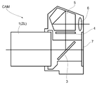
- FIG. 12 shows a schematic cross-sectional view of a digital single-lens reflex camera CAM (imaging device) provided with the above-described zoom optical system ZL as the photographing lens 1.
- a digital single-lens reflex camera CAM imaging device
- zoom optical system ZL zoom optical system
- the quick return mirror 3 is retracted out of the optical path, and light of an object (subject) (not shown) condensed by the photographing lens 1 is captured on the image sensor 7. Form an image. Thereby, the light from the object (subject) is captured by the image sensor 7 and recorded as an object (subject) image in a memory (not shown). In this way, the photographer can photograph an object (subject) with the camera CAM.
- the camera CAM may hold the photographic lens 1 in a detachable manner, or may be formed integrally with the photographic lens 1.
- the camera CAM may be a so-called single-lens reflex camera or a compact camera that does not have a quick return mirror or the like.
- the zoom optical system ZL according to the present embodiment mounted on the camera CAM as the photographing lens 1 is small in size and starts to exhibit chromatic aberration over the entire zoom range, as can be seen from each example described later.
- the above-mentioned various aberrations are corrected satisfactorily and high optical performance is achieved. Therefore, the camera CAM is small, can correct various aberrations including chromatic aberration over the entire zoom range, and can realize an imaging apparatus having high optical performance.
- f is the focal length (mm) of the zoom optical system ZL at the d-line at the wide-angle end state and the telephoto end state
- FNo is the F-number at the wide-angle end state and the telephoto end state
- Y represents the image height
- ⁇ d represents the distance on the optical axis from the most object side lens surface (first surface) of the zoom optical system ZL to the most image side lens surface.
- the surface number indicates the order of the lens surfaces from the object side along the direction in which the light beam travels
- R indicates the radius of curvature of each lens surface
- d indicates the next optical surface from each optical surface.
- the distance between the surfaces which is the distance on the optical axis to (or the image plane)
- nd is the refractive index with respect to the d-line (wavelength 587.562 nm) of the glass material used for the lens
- ⁇ d is the d-line of the glass material used for the lens.
- Di (variable) is the variable surface spacing of the i-th surface
- * a is an aspherical surface
- * d is a diffractive optical surface
- * s is an aperture
- “ ⁇ ” in the column of curvature radius R is Shows a plane.
- the description of the refractive index of air (d-line) “1.000000” is omitted.
- ⁇ (h) (2 ⁇ / ⁇ ) ⁇ (C2h 2 + C4h 4 + C6h 6 + C8h 8 + C10h 10 ) (b)
- G represents a group number
- the first group surface represents the surface number closest to the object side of each lens group
- the group focal length represents the focal length of each lens group.
- the units of focal length f, radius of curvature R, surface interval d, and other lengths in the table are “mm”. However, since the optical system can obtain the same optical performance even if it is proportionally enlarged or reduced, the unit is not limited to “mm”, and other appropriate units can be used.
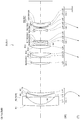
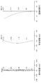
- FIG. 2 is a structural sectional view of the zoom optical system ZL (ZL1) according to the first embodiment and a zoom trajectory from the wide-angle end state (W) to the telephoto end state (T).
- ZL1 and PF2 of the diffractive optical element elements constituting the diffractive optical element PF in order to avoid the complexity of the illustration, reference numerals PF1 and PF2 of the diffractive optical element elements constituting the diffractive optical element PF, description of reference numeral C of the diffractive optical surface, and description of the shape of the grating grooves Is omitted, and only the sign of the diffractive optical element PF is described.
- the zoom optical system ZL1 has a first lens group G1 having negative refractive power, which is arranged in order from the object side along the optical axis, and has positive refractive power.
- the lens unit includes a second lens group G2, a third lens group G3 having a negative refractive power, a fourth lens group G4 having a positive refractive power, and a fifth lens group G5 having a positive refractive power.
- the distance between the first lens group G1 and the second lens group G2 changes from the wide-angle end state to the telephoto end state, and the distance between the second lens group G2 and the third lens group G3 increases.
- the first lens group G1 is convex toward the object side so that the distance between the third lens group G3 and the fourth lens group G4 decreases and the distance between the fourth lens group G4 and the fifth lens group G5 increases.
- the second lens group moves to the object side
- the third lens group G3 moves to the object side
- the fourth lens group G4 moves to the object side.
- the fifth lens group G5 is fixed and does not move during zooming.
- the first lens group G1 is arranged in order from the object side along the optical axis, a meniscus first negative lens L11 having a convex surface facing the object side, a second negative lens L12 having a biconcave lens shape, an object And a meniscus positive lens L13 having a convex surface on the side.
- a contact multilayer diffractive optical element PF is provided on the image side lens surface of the first negative lens L11, and this surface is aspherical.
- the diffractive optical element PF is configured by closely joining diffractive optical element elements PF1 and PF2 made of two different ultraviolet curable resins, and the joint surface thereof is a diffractive optical surface C on which a diffraction grating groove is formed. (See FIG. 1).
- a resin having a refractive index shown in [Resin refractive index] in the following table was used as a constituent material of the diffractive optical element elements PF1 and PF2.
- the resin refractive index indicates the refractive index after resin curing.
- the second lens group G2 includes a positive lens L21, a cemented lens of a negative lens L22 and a positive lens L23, and a positive lens L24, which are arranged in order from the object side along the optical axis.
- the third lens group G3 includes a cemented lens of a positive lens L31 and a negative lens L32, and a negative lens L33, which are arranged in order from the object side along the optical axis.
- the fourth lens group G4 includes a cemented lens of a negative lens L41 and a positive lens L42, and a negative lens L43, which are arranged in order from the object side along the optical axis.
- the object side lens surface of the negative lens L41 is aspheric.
- the fifth lens group G5 is composed of a cemented lens of a positive lens L51 and a negative lens L52 arranged in order from the object side along the optical axis.
- the stop SP is disposed on the object side of the third lens group G3.
- the aperture stop SP moves together with the third lens group G3 from the wide-angle end state to the telephoto end state during zooming.
- Table 1 below shows each specification value of the zoom optical system ZL1 according to the first example.
- the surface numbers 1 to 30 in Table 1 correspond to the optical surfaces having the curvature radii R1 to R30 shown in FIG.
- Table 1 shows that the zoom optical system ZL1 according to the first example satisfies the conditional expressions (1) to (7).
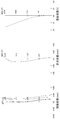
- FIG. 3 and 4 are graphs showing various aberrations of the zoom lens system ZL according to Example 1.
- FIG. 3 is a longitudinal aberration diagram at an imaging distance of infinity in the wide-angle end state
- FIG. 4 is a longitudinal aberration diagram at an imaging distance of infinity in the telephoto end state.
- spherical aberration astigmatism
- astigmatism astigmatism
- distortion are described from the left side in each figure.
- Each aberration diagram is a ray trace of the zoom optical system ZL1 according to the first example from the object side.
- d indicates the aberration at the d-line (wavelength 587.562 nm)
- C indicates the C-line (wavelength 656.273 nm)
- F indicates the F-line (wavelength 486.133 nm)
- g indicates the aberration at the g-line (wavelength 435.835 nm).
- the vertical axis indicates the value normalized by setting the maximum value of the entrance pupil radius to 1, and the horizontal axis indicates the aberration value (mm) in each line.
- the astigmatism diagram shows aberration at the d-line
- the solid line S shows the sagittal image plane
- the broken line T shows the meridional image plane.
- the vertical axis represents the image height (mm) and the horizontal axis represents the aberration value (mm).
- the distortion diagram shows the aberration at the d-line.
- the vertical axis represents the image height (mm)
- the horizontal axis represents the aberration ratio (percentage (% value)).
- the zoom optical system ZL1 according to the first example includes various aberrations including spherical aberration, astigmatism, distortion aberration, etc. in each focal length state from the wide-angle end state to the telephoto end state. It can be seen that the aberration is corrected well.
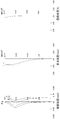
- FIG. 5 shows a sectional view of the zoom optical system ZL (ZL2) according to the second embodiment and the zoom trajectory from the wide-angle end state (W) to the telephoto end state (T).
- ZL2 zoom optical system
- W wide-angle end state
- T telephoto end state
- reference numerals PF1 and PF2 of the diffractive optical element elements constituting the diffractive optical element PF description of reference numeral C of the diffractive optical surface, and description of the shape of the grating grooves Is omitted, and only the sign of the diffractive optical element PF is described.
- the zoom optical system ZL2 has a first lens group G1 having negative refractive power arranged in order from the object side along the optical axis, and has positive refractive power.
- the lens unit includes a second lens group G2, a third lens group G3 having a negative refractive power, a fourth lens group G4 having a positive refractive power, and a fifth lens group G5 having a positive refractive power.
- the distance between the first lens group G1 and the second lens group G2 changes from the wide-angle end state to the telephoto end state, and the distance between the second lens group G2 and the third lens group G3 increases.
- the first lens group G1 is convex toward the object side so that the distance between the third lens group G3 and the fourth lens group G4 decreases and the distance between the fourth lens group G4 and the fifth lens group G5 increases.
- the second lens group moves to the object side
- the third lens group G3 moves to the object side
- the fourth lens group G4 moves to the object side.
- the fifth lens group G5 is fixed and does not move during zooming.
- the first lens group G1 is arranged in order from the object side along the optical axis, a meniscus first negative lens L11 having a convex surface facing the object side, a second negative lens L12 having a biconcave lens shape, an object And a meniscus positive lens L13 having a convex surface on the side.
- a contact multilayer diffractive optical element PF is provided on the image side lens surface of the first negative lens L11, and this surface is aspherical.
- the diffractive optical element PF is configured by closely joining diffractive optical element elements PF1 and PF2 made of two different ultraviolet curable resins, and the joint surface thereof is a diffractive optical surface C on which a diffraction grating groove is formed. (See FIG. 1).
- a resin having a refractive index shown in [Resin refractive index] in the following table was used as a constituent material of the diffractive optical element elements PF1 and PF2.
- the resin refractive index indicates the refractive index after resin curing.
- the second lens group G2 includes a positive lens L21, a cemented lens of a negative lens L22 and a positive lens L23, and a positive lens L24, which are arranged in order from the object side along the optical axis.
- the third lens group G3 includes a cemented lens of a positive lens L31 and a negative lens L32, and a negative lens L33, which are arranged in order from the object side along the optical axis.
- the fourth lens group G4 includes a cemented lens of a negative lens L41 and a positive lens L42, and a negative lens L43, which are arranged in order from the object side along the optical axis.
- the object side lens surface of the negative lens L41 is aspheric.
- the fifth lens group G5 includes a positive lens L51.
- the stop SP is disposed on the object side of the third lens group G3.
- the aperture stop SP moves together with the third lens group G3 from the wide-angle end state to the telephoto end state during zooming.
- Table 2 below shows each specification value of the zoom optical system ZL2 according to the second example.
- Surface numbers 1 to 29 in Table 2 correspond to the optical surfaces having the curvature radii R1 to R29 shown in FIG.
- Table 2 shows that the zoom optical system ZL2 according to the second example satisfies the conditional expressions (1) to (7).
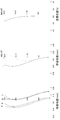
- FIG. 6 and 7 are graphs showing various aberrations of the zoom lens system ZL according to Example 2.
- FIG. 6 is a longitudinal aberration diagram at an imaging distance of infinity in the wide-angle end state
- FIG. 7 is a longitudinal aberration diagram at an imaging distance of infinity in the telephoto end state.
- spherical aberration astigmatism
- astigmatism astigmatism
- distortion are described from the left side in each figure.
- Each aberration diagram is obtained by tracing light rays from the object side in the zoom optical system ZL2 according to the second example.
- the zoom optical system ZL2 according to the second example includes various aberrations including spherical aberration, astigmatism, distortion aberration, etc. in each focal length state from the wide-angle end state to the telephoto end state. It can be seen that the aberration is corrected well.
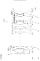
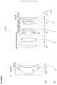
- FIG. 8 shows a sectional view of the zoom optical system ZL (ZL3) according to the third example and the zoom trajectory from the wide-angle end state (W) to the telephoto end state (T).
- ZL3 zoom optical system ZL
- W wide-angle end state
- T telephoto end state
- reference numerals PF1 and PF2 of the diffractive optical element elements constituting the diffractive optical element PF description of reference numeral C of the diffractive optical surface, and description of the shape of the grating grooves Is omitted, and only the sign of the diffractive optical element PF is described.
- the zoom optical system ZL3 has a first lens group G1 having a negative refractive power arranged in order from the object side along the optical axis, and a positive refractive power.
- the lens unit includes a second lens group G2, a third lens group G3 having a negative refractive power, a fourth lens group G4 having a positive refractive power, and a fifth lens group G5 having a positive refractive power.
- the distance between the first lens group G1 and the second lens group G2 changes from the wide-angle end state to the telephoto end state, and the distance between the second lens group G2 and the third lens group G3 increases.
- the first lens group G1 is convex toward the object side so that the distance between the third lens group G3 and the fourth lens group G4 decreases and the distance between the fourth lens group G4 and the fifth lens group G5 increases.
- the second lens group moves to the object side
- the third lens group G3 moves to the object side
- the fourth lens group G4 moves to the object side.
- the fifth lens group G5 is fixed and does not move during zooming.
- the first lens group G1 is arranged in order from the object side along the optical axis, a meniscus first negative lens L11 having a convex surface facing the object side, a second negative lens L12 having a biconcave lens shape, an object And a meniscus positive lens L13 having a convex surface on the side.
- a contact multilayer diffractive optical element PF is provided on the image side lens surface of the first negative lens L11, and this surface is aspherical.
- the diffractive optical element PF is configured by closely joining diffractive optical element elements PF1 and PF2 made of two different ultraviolet curable resins, and the joint surface thereof is a diffractive optical surface C on which a diffraction grating groove is formed. (See FIG. 1).
- a resin having a refractive index shown in [Resin refractive index] in the following table was used as a constituent material of the diffractive optical element elements PF1 and PF2.
- the resin refractive index indicates the refractive index after resin curing.
- the second lens group G2 includes a positive lens L21, a cemented lens of a negative lens L22 and a positive lens L23, and a positive lens L24, which are arranged in order from the object side along the optical axis.
- the third lens group G3 includes a cemented lens of a positive lens L31 and a negative lens L32, and a negative lens L33, which are arranged in order from the object side along the optical axis.
- the fourth lens group G4 includes a cemented lens of a negative lens L41 and a positive lens L42, and a negative lens L43, which are arranged in order from the object side along the optical axis.
- the object side lens surface of the negative lens L41 is aspheric.
- the fifth lens group G5 includes a positive lens L51.
- an aperture stop SP is disposed on the object side of the third lens group G3.
- the aperture stop SP moves together with the third lens group G3 from the wide-angle end state to the telephoto end state during zooming.
- Table 3 below shows specifications of the zoom optical system ZL3 according to the third example.
- Surface numbers 1 to 29 in Table 3 correspond to the optical surfaces having the curvature radii R1 to R29 shown in FIG.
- FIG. 9 and 10 are graphs showing various aberrations of the zoom lens system ZL according to Example 3.
- FIG. 9 is a longitudinal aberration diagram at an imaging distance of infinity in the wide-angle end state
- FIG. 10 is a longitudinal aberration diagram at an imaging distance of infinity in the telephoto end state.
- spherical aberration astigmatism
- astigmatism astigmatism
- distortion are described from the left side in each figure.
- Each aberration diagram is a ray trace of the zoom optical system ZL3 according to the third example from the object side.
- the zoom optical system ZL3 according to the third example includes various aberrations including spherical aberration, astigmatism, distortion aberration, etc. in each focal length state from the wide-angle end state to the telephoto end state. It can be seen that the aberration is corrected well.
- the present invention by effectively using a diffractive optical element, it is small in size, and it corrects various aberrations including chromatic aberration over the entire zoom range and has high optical performance.
- the zoom optical system can be provided.
Priority Applications (4)
| Application Number | Priority Date | Filing Date | Title |
|---|---|---|---|
| IN3496DEN2014 IN2014DN03496A (zh) | 2012-02-29 | 2013-02-21 | |
| CN201380005147.3A CN104040405B (zh) | 2012-02-29 | 2013-02-21 | 变焦光学系统 |
| JP2014502014A JP5854124B2 (ja) | 2012-02-29 | 2013-02-21 | ズーム光学系及び撮像装置 |
| US14/291,155 US9535240B2 (en) | 2012-02-29 | 2014-05-30 | Zoom optical system |
Applications Claiming Priority (2)
| Application Number | Priority Date | Filing Date | Title |
|---|---|---|---|
| JP2012-043926 | 2012-02-29 | ||
| JP2012043926 | 2012-02-29 |
Related Child Applications (1)
| Application Number | Title | Priority Date | Filing Date |
|---|---|---|---|
| US14/291,155 Continuation US9535240B2 (en) | 2012-02-29 | 2014-05-30 | Zoom optical system |
Publications (1)
| Publication Number | Publication Date |
|---|---|
| WO2013128856A1 true WO2013128856A1 (ja) | 2013-09-06 |
Family
ID=49082071
Family Applications (1)
| Application Number | Title | Priority Date | Filing Date |
|---|---|---|---|
| PCT/JP2013/000984 WO2013128856A1 (ja) | 2012-02-29 | 2013-02-21 | ズーム光学系 |
Country Status (5)
| Country | Link |
|---|---|
| US (1) | US9535240B2 (zh) |
| JP (1) | JP5854124B2 (zh) |
| CN (1) | CN104040405B (zh) |
| IN (1) | IN2014DN03496A (zh) |
| WO (1) | WO2013128856A1 (zh) |
Cited By (5)
| Publication number | Priority date | Publication date | Assignee | Title |
|---|---|---|---|---|
| JP2015094884A (ja) * | 2013-11-13 | 2015-05-18 | 富士フイルム株式会社 | ズームレンズおよび撮像装置 |
| WO2016121926A1 (ja) * | 2015-01-30 | 2016-08-04 | 株式会社ニコン | ズームレンズ、光学機器、およびズームレンズの製造方法 |
| WO2016121944A1 (ja) * | 2015-01-30 | 2016-08-04 | 株式会社ニコン | ズームレンズ、光学機器、およびズームレンズの製造方法 |
| CN106124063A (zh) * | 2016-08-30 | 2016-11-16 | 福建福光天瞳光学有限公司 | 超大视场长波红外光学无热化测温镜头及其制造方法 |
| US10281693B2 (en) | 2014-05-09 | 2019-05-07 | Nikon Corporation | Inverted equal-magnification relay lens and camera system |
Families Citing this family (6)
| Publication number | Priority date | Publication date | Assignee | Title |
|---|---|---|---|---|
| CN111458856A (zh) * | 2015-01-30 | 2020-07-28 | 株式会社尼康 | 变焦镜头以及光学设备 |
| JP6649287B2 (ja) * | 2017-01-05 | 2020-02-19 | 富士フイルム株式会社 | ズームレンズおよび撮像装置 |
| CN108572433B (zh) * | 2017-03-10 | 2020-12-29 | 湖北华中光电科技有限公司 | 一种二元面高倍变焦镜头 |
| WO2019116567A1 (ja) * | 2017-12-15 | 2019-06-20 | 株式会社ニコン | 光学系、光学機器、および光学系の製造方法 |
| WO2019229817A1 (ja) * | 2018-05-28 | 2019-12-05 | 株式会社ニコン | 光学系、光学機器、および光学系の製造方法 |
| CN111308654B (zh) * | 2020-02-28 | 2022-05-20 | 江苏大学 | 一种用于微弱光信号收集的变焦光学系统 |
Citations (10)
| Publication number | Priority date | Publication date | Assignee | Title |
|---|---|---|---|---|
| JPH1152237A (ja) * | 1997-08-01 | 1999-02-26 | Canon Inc | ズームレンズ |
| JPH1152235A (ja) * | 1997-07-31 | 1999-02-26 | Canon Inc | ズームレンズ |
| JP2000009999A (ja) * | 1998-06-19 | 2000-01-14 | Minolta Co Ltd | ズームレンズ |
| JP2000066092A (ja) * | 1998-08-17 | 2000-03-03 | Nikon Corp | 結像光学系 |
| JP2000147380A (ja) * | 1998-11-10 | 2000-05-26 | Canon Inc | ズームレンズ及びカメラ |
| JP2002196236A (ja) * | 2000-12-22 | 2002-07-12 | Canon Inc | ズームレンズ及びそれを用いた光学機器 |
| JP2003021783A (ja) * | 2001-07-06 | 2003-01-24 | Canon Inc | ズームレンズ及びそれを用いた光学機器 |
| JP2006084971A (ja) * | 2004-09-17 | 2006-03-30 | Canon Inc | ズームレンズ及びそれを有する画像投射装置 |
| JP2009251117A (ja) * | 2008-04-02 | 2009-10-29 | Panasonic Corp | ズームレンズ系、交換レンズ装置、及びカメラシステム |
| JP2010217535A (ja) * | 2009-03-17 | 2010-09-30 | Nikon Corp | 撮影レンズ、この撮影レンズを備えた光学機器、及び、撮影レンズの製造方法 |
Family Cites Families (8)
| Publication number | Priority date | Publication date | Assignee | Title |
|---|---|---|---|---|
| US6081389A (en) | 1997-07-31 | 2000-06-27 | Canon Kabushiki Kaisha | Zoom lens of retrofocus type |
| JP2004117826A (ja) | 2002-09-26 | 2004-04-15 | Minolta Co Ltd | 撮像装置 |
| JP4872671B2 (ja) | 2004-12-20 | 2012-02-08 | 株式会社ニコン | 密着複層型回折光学素子 |
| WO2006068137A1 (ja) | 2004-12-20 | 2006-06-29 | Nikon Corporation | 密着複層型回折光学素子、それに用いられる光学材料、樹脂前駆体及び樹脂前駆体組成物 |
| JP4898410B2 (ja) * | 2006-12-14 | 2012-03-14 | キヤノン株式会社 | ズームレンズ及びそれを有する撮像装置 |
| CN102084279B (zh) * | 2009-08-25 | 2013-02-06 | 佳能株式会社 | 光学系统和包括光学系统的光学装置 |
| JP2012150432A (ja) * | 2010-12-28 | 2012-08-09 | Panasonic Corp | ズームレンズ系、撮像装置及びカメラ |
| JP5885518B2 (ja) * | 2012-01-30 | 2016-03-15 | キヤノン株式会社 | 撮影光学系及びそれを有する撮像装置 |
-
2013
- 2013-02-21 CN CN201380005147.3A patent/CN104040405B/zh not_active Expired - Fee Related
- 2013-02-21 IN IN3496DEN2014 patent/IN2014DN03496A/en unknown
- 2013-02-21 JP JP2014502014A patent/JP5854124B2/ja active Active
- 2013-02-21 WO PCT/JP2013/000984 patent/WO2013128856A1/ja active Application Filing
-
2014
- 2014-05-30 US US14/291,155 patent/US9535240B2/en active Active
Patent Citations (10)
| Publication number | Priority date | Publication date | Assignee | Title |
|---|---|---|---|---|
| JPH1152235A (ja) * | 1997-07-31 | 1999-02-26 | Canon Inc | ズームレンズ |
| JPH1152237A (ja) * | 1997-08-01 | 1999-02-26 | Canon Inc | ズームレンズ |
| JP2000009999A (ja) * | 1998-06-19 | 2000-01-14 | Minolta Co Ltd | ズームレンズ |
| JP2000066092A (ja) * | 1998-08-17 | 2000-03-03 | Nikon Corp | 結像光学系 |
| JP2000147380A (ja) * | 1998-11-10 | 2000-05-26 | Canon Inc | ズームレンズ及びカメラ |
| JP2002196236A (ja) * | 2000-12-22 | 2002-07-12 | Canon Inc | ズームレンズ及びそれを用いた光学機器 |
| JP2003021783A (ja) * | 2001-07-06 | 2003-01-24 | Canon Inc | ズームレンズ及びそれを用いた光学機器 |
| JP2006084971A (ja) * | 2004-09-17 | 2006-03-30 | Canon Inc | ズームレンズ及びそれを有する画像投射装置 |
| JP2009251117A (ja) * | 2008-04-02 | 2009-10-29 | Panasonic Corp | ズームレンズ系、交換レンズ装置、及びカメラシステム |
| JP2010217535A (ja) * | 2009-03-17 | 2010-09-30 | Nikon Corp | 撮影レンズ、この撮影レンズを備えた光学機器、及び、撮影レンズの製造方法 |
Cited By (10)
| Publication number | Priority date | Publication date | Assignee | Title |
|---|---|---|---|---|
| JP2015094884A (ja) * | 2013-11-13 | 2015-05-18 | 富士フイルム株式会社 | ズームレンズおよび撮像装置 |
| US10281693B2 (en) | 2014-05-09 | 2019-05-07 | Nikon Corporation | Inverted equal-magnification relay lens and camera system |
| WO2016121926A1 (ja) * | 2015-01-30 | 2016-08-04 | 株式会社ニコン | ズームレンズ、光学機器、およびズームレンズの製造方法 |
| WO2016121944A1 (ja) * | 2015-01-30 | 2016-08-04 | 株式会社ニコン | ズームレンズ、光学機器、およびズームレンズの製造方法 |
| JPWO2016121926A1 (ja) * | 2015-01-30 | 2017-11-02 | 株式会社ニコン | ズームレンズ、光学機器、およびズームレンズの製造方法 |
| JPWO2016121944A1 (ja) * | 2015-01-30 | 2017-11-02 | 株式会社ニコン | ズームレンズ、光学機器、およびズームレンズの製造方法 |
| JP2019070827A (ja) * | 2015-01-30 | 2019-05-09 | 株式会社ニコン | ズームレンズ |
| JP2019164375A (ja) * | 2015-01-30 | 2019-09-26 | 株式会社ニコン | ズームレンズ、および光学機器 |
| CN106124063A (zh) * | 2016-08-30 | 2016-11-16 | 福建福光天瞳光学有限公司 | 超大视场长波红外光学无热化测温镜头及其制造方法 |
| CN106124063B (zh) * | 2016-08-30 | 2022-11-15 | 福建福光天瞳光学有限公司 | 超大视场长波红外光学无热化测温镜头及其制造方法 |
Also Published As
| Publication number | Publication date |
|---|---|
| CN104040405A (zh) | 2014-09-10 |
| US9535240B2 (en) | 2017-01-03 |
| JP5854124B2 (ja) | 2016-02-09 |
| JPWO2013128856A1 (ja) | 2015-07-30 |
| CN104040405B (zh) | 2017-05-03 |
| IN2014DN03496A (zh) | 2015-06-05 |
| US20140268363A1 (en) | 2014-09-18 |
Similar Documents
| Publication | Publication Date | Title |
|---|---|---|
| JP5854124B2 (ja) | ズーム光学系及び撮像装置 | |
| JP4630645B2 (ja) | 光学系 | |
| JP4898410B2 (ja) | ズームレンズ及びそれを有する撮像装置 | |
| US7133221B2 (en) | Lens system and optical device having the same | |
| JP5074790B2 (ja) | ズームレンズ及びそれを有する撮像装置 | |
| JP5366673B2 (ja) | 光学系及びそれを有する光学機器 | |
| US7545577B2 (en) | Zoom lens and image pickup apparatus including the same | |
| US10670848B2 (en) | Variable power optical system, optical device and method for manufacturing variable power optical system | |
| JP2002244044A (ja) | ズームレンズ及びそれを用いた光学機器 | |
| US9229199B2 (en) | Zoom lens system, imaging apparatus, and method for manufacturing zoom lens system | |
| JP5641461B2 (ja) | ズーム光学系及びこれを有する撮像装置 | |
| JP5202014B2 (ja) | 光学系及びそれを用いた光学機器 | |
| JP5202025B2 (ja) | 撮像光学系及びそれを有する撮像装置 | |
| JP2012078397A (ja) | 回折格子を含む光学系および光学機器 | |
| JP5510784B2 (ja) | ズームレンズ、光学機器 | |
| JP6938841B2 (ja) | ズームレンズ及び光学機器 | |
| JP4860500B2 (ja) | 色消しレンズ系、光学装置 | |
| JP5845887B2 (ja) | ズームレンズおよび撮像装置 | |
| JP6635250B2 (ja) | 撮像光学系及びそれを有する撮像装置 | |
| US20020131184A1 (en) | Zoom lens system, image projecting and image pick-up devices using the same | |
| JP5935879B2 (ja) | ズームレンズ及び光学機器 | |
| JP6784952B2 (ja) | 光学系及び光学機器 | |
| JP2000147379A (ja) | ズームレンズ | |
| JP5317553B2 (ja) | 光学系及びそれを用いた光学機器、撮像装置並びに投影装置 | |
| US20220091400A1 (en) | Variable magnification optical system, optical equipment, and method for producing variable magnification optical system |
Legal Events
| Date | Code | Title | Description |
|---|---|---|---|
| 121 | Ep: the epo has been informed by wipo that ep was designated in this application |
Ref document number: 13754493 Country of ref document: EP Kind code of ref document: A1 |
|
| ENP | Entry into the national phase |
Ref document number: 2014502014 Country of ref document: JP Kind code of ref document: A |
|
| NENP | Non-entry into the national phase |
Ref country code: DE |
|
| 122 | Ep: pct application non-entry in european phase |
Ref document number: 13754493 Country of ref document: EP Kind code of ref document: A1 |