US9229199B2 - Zoom lens system, imaging apparatus, and method for manufacturing zoom lens system - Google Patents
Zoom lens system, imaging apparatus, and method for manufacturing zoom lens system Download PDFInfo
- Publication number
- US9229199B2 US9229199B2 US14/111,542 US201214111542A US9229199B2 US 9229199 B2 US9229199 B2 US 9229199B2 US 201214111542 A US201214111542 A US 201214111542A US 9229199 B2 US9229199 B2 US 9229199B2
- Authority
- US
- United States
- Prior art keywords
- group
- lens
- denotes
- refractive power
- zoom lens
- Prior art date
- Legal status (The legal status is an assumption and is not a legal conclusion. Google has not performed a legal analysis and makes no representation as to the accuracy of the status listed.)
- Active, expires
Links
Images


Classifications
-
- G—PHYSICS
- G02—OPTICS
- G02B—OPTICAL ELEMENTS, SYSTEMS OR APPARATUS
- G02B15/00—Optical objectives with means for varying the magnification
- G02B15/14—Optical objectives with means for varying the magnification by axial movement of one or more lenses or groups of lenses relative to the image plane for continuously varying the equivalent focal length of the objective
- G02B15/143—Optical objectives with means for varying the magnification by axial movement of one or more lenses or groups of lenses relative to the image plane for continuously varying the equivalent focal length of the objective having three groups only
- G02B15/1435—Optical objectives with means for varying the magnification by axial movement of one or more lenses or groups of lenses relative to the image plane for continuously varying the equivalent focal length of the objective having three groups only the first group being negative
- G02B15/143503—Optical objectives with means for varying the magnification by axial movement of one or more lenses or groups of lenses relative to the image plane for continuously varying the equivalent focal length of the objective having three groups only the first group being negative arranged -+-
-
- G—PHYSICS
- G02—OPTICS
- G02B—OPTICAL ELEMENTS, SYSTEMS OR APPARATUS
- G02B13/00—Optical objectives specially designed for the purposes specified below
- G02B13/04—Reversed telephoto objectives
-
- G—PHYSICS
- G02—OPTICS
- G02B—OPTICAL ELEMENTS, SYSTEMS OR APPARATUS
- G02B15/00—Optical objectives with means for varying the magnification
- G02B15/14—Optical objectives with means for varying the magnification by axial movement of one or more lenses or groups of lenses relative to the image plane for continuously varying the equivalent focal length of the objective
- G02B15/16—Optical objectives with means for varying the magnification by axial movement of one or more lenses or groups of lenses relative to the image plane for continuously varying the equivalent focal length of the objective with interdependent non-linearly related movements between one lens or lens group, and another lens or lens group
- G02B15/177—Optical objectives with means for varying the magnification by axial movement of one or more lenses or groups of lenses relative to the image plane for continuously varying the equivalent focal length of the objective with interdependent non-linearly related movements between one lens or lens group, and another lens or lens group having a negative front lens or group of lenses
-
- Y—GENERAL TAGGING OF NEW TECHNOLOGICAL DEVELOPMENTS; GENERAL TAGGING OF CROSS-SECTIONAL TECHNOLOGIES SPANNING OVER SEVERAL SECTIONS OF THE IPC; TECHNICAL SUBJECTS COVERED BY FORMER USPC CROSS-REFERENCE ART COLLECTIONS [XRACs] AND DIGESTS
- Y10—TECHNICAL SUBJECTS COVERED BY FORMER USPC
- Y10T—TECHNICAL SUBJECTS COVERED BY FORMER US CLASSIFICATION
- Y10T29/00—Metal working
- Y10T29/49—Method of mechanical manufacture
- Y10T29/49826—Assembling or joining
Definitions
- the present invention relates to a zoom lens system that is suitable for a phototaking optical system used in a digital camera, a film camera, a video camera or the like, an imaging apparatus, and a method for manufacturing the zoom lens system.
- the conventional zoom lens system as above-mentioned has not been made satisfactorily compact in size.
- a zoom lens of a type that is intended to be compact in size but also advantageous for correcting astigmatism, curvature of field, coma and spherical aberration, has been sought to be attained.
- the present invention is made in view of the above described problems and has an object to provide a zoom lens system which is compact in size and has small back focus and excellent optical performance, an imaging apparatus, and a method for manufacturing the zoom lens system.
- a zoom lens system comprising, in order from an object side: a front group having negative refractive power; and a rear group having positive refractive power;
- zooming being carried out by varying a distance between said front group and said rear group;
- said front group having, at least, a negative lens and a positive lens
- said rear group having, in order from the object side, a first partial group having a positive refractive power, a second partial group having a negative refractive power, a third partial group having a positive refractive power, and a negative lens;
- r1 denotes a curvature radius of an object side lens surface of said negative lens in said rear group
- r2 denotes a curvature radius of an image side lens surface of said negative lens in said rear group
- fw denotes a focal length of the entire zoom lens system upon focusing on an infinitely distant object in the wide-angle end state
- BFw denotes a back focus of the entire zoom lens system upon focusing on the infinitely distant object in the wide-angle end state
- f2 denotes a focal length of said rear group.
- an imaging apparatus equipped with the zoom lens system relating to the first aspect of the present invention.
- a zoom lens system comprising, in order from an object side: a front group having a negative refractive power, and a rear group having a positive refractive power, comprising steps of:
- said front group to include, at least, a negative lens and a positive lens
- said rear group to include, in order from the object side, a first partial group having positive refractive power, a second partial group having negative refractive power, a third partial group having positive refractive power, and a negative lens;
- r1 denotes a curvature radius of an object side lens surface of said negative lens in said rear group
- r2 denotes a curvature radius of an image side lens surface of said negative lens in said rear group
- fw denotes a focal length of the entire zoom lens system upon focusing on an infinitely distant object in the wide-angle end state
- BFw denotes a back focus of the entire zoom lens system upon focusing on the infinitely distant object in the wide-angle end state
- f2 denotes a focal length of said rear group
- a zoom lens system that is compact in size and has a small back focus and excellent optical performance, an imaging apparatus and a method for manufacturing the zoom lens system.
- FIG. 1 is a sectional view showing a lens configuration of a zoom lens system according to Example 1 of the present application.
- FIGS. 2A , 2 B and 2 C are graphs, respectively, showing various aberrations upon focusing on an infinitely distant object in the wide-angle end state, in an intermediate focal length state and in the telephoto end state of the zoom lens system according to Example 1 of the present application.
- FIG. 3 is a sectional view showing a lens configuration of a zoom lens system according to Example 2 of the present application.
- FIGS. 4A , 4 B and 4 C are graphs, respectively, showing various aberrations upon focusing on an infinitely distant object in the wide-angle end state, in an intermediate focal length state and in the telephoto end state of the zoom lens system according to Example 2 of the present application.
- FIG. 5 is a sectional view showing a lens configuration of a zoom lens system according to Example 3 of the present application.
- FIGS. 6A , 6 B and 6 C are graphs, respectively, showing various aberrations upon focusing on an infinitely distant object in the wide-angle end state, in an intermediate focal length state and in the telephoto end state of the zoom lens system according to Example 3 of the present application.
- FIG. 7 is a sectional view showing a lens configuration of a zoom lens system according to Example 4 of the present application.
- FIGS. 8A , 8 B and 8 C are graphs, respectively, showing various aberrations upon focusing on an infinitely distant object in the wide-angle end state, in an intermediate focal length state and in the telephoto end state of the zoom lens system according to the Example 4 of the present application.
- FIG. 9 is a sectional view showing a lens configuration of a zoom lens system according to Example 5 of the present application.
- FIGS. 10A , 10 B and 10 C are graphs, respectively, showing various aberrations upon focusing on an infinitely distant object in the wide-angle end state, in an intermediate focal length state and in the telephoto end state of the zoom lens system according to the Example 5 of the present application.
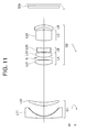
- FIG. 11 is a sectional view showing a lens configuration of a zoom lens system according to Example 6 of the present application.
- FIGS. 12A , 12 B and 12 C are graphs, respectively, showing various aberrations upon focusing on an infinitely distant object in the wide-angle end state, in an intermediate focal length state and in the telephoto end state of the zoom lens system according to the Example 6 of the present application.
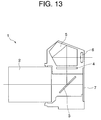
- FIG. 13 is a diagram showing a construction of a camera equipped with the zoom lens system according to the present application.
- FIG. 14 is a flowchart showing a method for manufacturing the zoom lens system according to the present application.
- a zoom lens system, an imaging apparatus, and a method for manufacturing the zoom lens system according to the present application are explained below.
- a zoom lens system includes, in order from an object side, a front group having a negative refractive power, and a rear group having a positive refractive power;
- zooming being carried out by varying a distance between said front group and said rear group;
- said front group having, at least, a negative lens and a positive lens
- said rear group having, in order from the object side, a first partial group having a positive refractive power, a second partial group having a negative refractive power, a third partial group having a positive refractive power, and a negative lens;
- r1 denotes a curvature radius of an object side lens surface of said negative lens in said rear group
- r2 denotes a curvature radius of an image side lens surface of said negative lens in said rear group
- fw denotes a focal length of the entire zoom lens system upon focusing on an infinitely distant object in the wide-angle end state
- BFw denotes a back focus of the entire zoom lens system upon focusing on the infinitely distant object in the wide-angle end state (meanwhile, in the cases where an optical low pass filter or alternative optical filter is disposed between the most image side lens and the image plane in said zoom lens system, the optical low pass filer or the alternative optical filter is removed to measure back focus, that is, air converted value of the back focus is calculated), and f2 denote
- a configuration of the rear group that is a master lens group covering focal length range from a wide-angle range to a standard range, and further to a telephoto range is mainly of modified triplet type or an Ernostar type whose basic structure is composed of positive-positive-negative-positive four partial groups from the object side in this order, due to relation between the principal point and the back focus.
- a mirror-less type digital camera has been developed, and a zoom lens system which has small back focus, and sufficient distance between the exit pupil and the image plane, and further which is compact in size and composed of less number of lenses, has been desired.
- the rear group is so configured to have positive-negative-positive-negative four partial groups from the object side in this order.
- back focus may be made small, a distance between the exit pupil and the image plane may be held satisfactorily, the number of lenses may be reduced and the system may be made compact.
- spherical aberration, coma, curvature radius and astigmatism may be well corrected, and excellent optical performance may be achieved.
- Conditional expression (1) defines inverse of shape factor (q-factor) of the negative lens in the rear group of the zoom lens system of the present application. If the value of 1/q becomes close to 0.00, that negative lens has a meniscus-shape in which curvature radius of the object side lens surface is extremely close to that of the image side lens surface.
- the zoom lens system of the present application can set a distance between the exit pupil and the image plane and the back focus to optimum values, and also various aberrations can be corrected well.
- the negative lens included in the rear group becomes a double concave negative lens.
- the distance between the exit pupil and the image plane and the back focus it is not possible to set the distance between the exit pupil and the image plane and the back focus to the respective optimum values so that it becomes not possible to attain the object of the present application.
- corrections of aberrations in particular, curvature of field, astigmatism and coma in the wide angle end state would be deteriorated, so it is not desirable.
- Conditional expression (2) defines the back focus of the zoom lens system according to the present application. With satisfying the conditional expression (2), it is possible to set a distance between the exit pupil and the image plane and the back focus of the zoom lens system of the present application to most proper values, and further various aberrations can be corrected satisfactorily.
- Conditional expression (3) defines a focal length of the rear group, in other words, is for setting the refractive power of the rear group.
- the zoom lens system according to the present application can set the refractive power of the rear group properly, so that various aberrations may be corrected well without making the zoom lens system of the present application large in size.
- the focal length of the rear group becomes large, which means that the refractive power of the rear group becomes small.
- the zoom lens system of the present application becomes large in size, so this is not desirable. Further, with respect to corrections of aberrations, this causes deteriorations in coma, so this is not preferable.
- said third partial group in said rear group consists of a single positive lens or two lenses.
- said third partial group in said rear group consists of two lenses which are cemented together.
- said first partial group in said rear group consists of a single positive lens or two positive lenses.
- said second partial group in said rear group consists of a single negative lens or two lenses.
- the zoom lens system of the present application satisfies the following conditional expression (4): 0.10 ⁇ ( ⁇ fd )/ f 2 ⁇ 6.00 (4), where fd denotes the focal length of said negative lens in said rear group; and f2 denotes the focal length of said rear group.
- Conditional expression (4) defines the focal length of the negative lens in the rear group, in other words, defines the refractive power of that negative lens.
- the zoom lens system of the present application satisfies the following conditional expression (5): 0.10 ⁇ fc/f 2 ⁇ 3.00 (5), where fc denotes the focal length of said third partial group in said rear group; and f2 denote the focal length of said rear group.
- Conditional expression (5) defines the focal length of the third partial group in the rear group, in other words, defines the refractive power of the third partial group.
- the focal length of the third partial group becomes small, which means that the positive refractive power of the third partial group becomes large.
- longitudinal chromatic aberration, coma, spherical aberration in the telephoto end state are deteriorated, so this is not preferable.
- the zoom lens system of the present application satisfies the following conditional expression (6): 0.01 ⁇ fa/f 2 ⁇ 3.00 (6), where fa denotes the focal length of said first partial group in said rear group; and f2 denote the focal length of said rear group.
- Conditional expression (6) defines the focal length of the first partial group in the rear group, in other words, defines the refractive power of the first partial group.
- the focal length of the first partial group becomes small, that is to say, the positive refractive power of the first partial group becomes large.
- coma and spherical aberration in the telephoto end state are deteriorated, so this is not preferable.
- the zoom lens system of the present application satisfies the following conditional expression (7): 0.10 ⁇ ( ⁇ fb )/ f 2 ⁇ 4.00 (7), where fb denotes the focal length of said second partial group in said rear group; and f2 denote the focal length of said rear group.
- Conditional expression (7) defines the focal length of the second partial group in said rear group, in other words, defines the refractive power of that second partial group.
- the zoom lens system of the present application includes an aperture stop between said first partial group and said second partial group.
- the imaging apparatus of the present application is characterized in the provision of the zoom lens system having a configuration as described above. By such a configuration, it is possible to realize an imaging apparatus that is compact in size and has small back focus and excellent optical performance.
- the method for manufacturing a zoom lens system according to the present application is a method for manufacturing a zoom lens system which includes, in order from an object side, a front group having negative refractive power, and a rear group having positive refractive power, the method comprising steps of:
- said front group with at least a negative lens and a positive lens
- arranging said front group and said rear group so that said front group and said rear group may satisfy the following conditional expressions (1) to (3): 0.00 ⁇ ( r 2 ⁇ r 1)/( r 2 +r 1) ⁇ 1.00 (1) 0.10 ⁇ BFw/fw ⁇ 2.00 (2) 0.90 ⁇ f 2 /fw ⁇ 5.00 (3)
- r1 denotes a curvature radius of an object side lens surface of said negative lens in said rear group
- r2 denotes a curvature radius of an image side lens surface of said negative lens in said rear group
- fw denotes a focal length of the entire zoom lens system upon focusing on an infinitely distant object in the wide-angle end state
- BFw denotes a back focus of the entire zoom lens system upon focusing on the infinitely distant object in the wide-angle end state
- f2 denotes a focal length of said rear lens group
- a zoom lens system that is compact in size and has small back focus and excellent optical performance may be manufactured.
- FIG. 1 is a sectional view showing a lens configuration of a zoom lens system and a zoom trajectory thereof according to Example 1 of the present application.
- the zoom lens system according to Example 1 is composed of, in order from an object side, a front group G 1 having negative refractive power, and a rear group G 2 having positive refractive power.
- the front group G 1 is composed of, in order from the object side, a negative meniscus lens L 11 having a convex surface facing the object side and a positive meniscus lens L 12 having a convex surface facing the object side.
- the negative meniscus lens L 11 is a socalled compound type aspherical lens which is composed of a resin layer and a glass substrate and whose aspherical surface is applied on the image plane side lens surface.
- the rear group G 2 is composed of, in order from the object side, a first partial group LA having positive refractive power, an aperture stop S, a second partial group LB having negative refractive power, a third partial group LC having positive refractive power and a negative meniscus lens LD having a convex surface facing the image side.
- the first partial group LA is composed of, in order from the object side, a double convex positive lens L 21 and a positive meniscus lens L 22 having a convex surface facing the object side.
- the second partial group LB is composed of only a cemented lens constructed by, in order from the object side, a double convex positive lens L 23 cemented with a double concave negative lens L 24 .
- the third partial group LC is composed of only a double convex positive lens L 25 .
- zooming from the wide angle end state to the telephoto end state is performed by varying a distance between the front group G 1 and the rear group G 2 .
- f denotes a focal length of the zoom lens system
- FNO denotes an f-number
- ⁇ denotes a half angle of view (unit “°”)
- Y denotes an image height
- TL denotes a total length the optical system
- ⁇ d denotes a distance between the most object side lens surface (first lens surface) and the most image side lens surface.
- W denotes upon focusing on an infinitely distant object in the wide-angle end state
- M denotes upon focusing on an infinitely distant object in an intermediate focal length state
- T denotes upon focusing on an infinitely distant object in the telephoto end state.
- m shows the lens surface number counted in order from the object side
- r shows a radius of curvature of the lens surface
- d shows a distance from a lens surface to the next lens surface
- OP denotes the object surface
- I denotes the image plane.
- the mark “*” put at the left side of the surface number shows an aspherical surface.
- d0 denotes a distance from the object surface OP to the first surface
- dm m: integer
- BF denotes a back focus
- ACBF denotes an air converted value of the back focus.
- mm is generally used for the unit of length such as the focal length f, and the radius of curvature r. However, since similar optical performance can be obtained by an optical system proportionally enlarged or reduced its dimension, the unit is not necessarily to be limited to “mm”.
- FIGS. 2A , 2 B and 2 C are graphs, respectively, showing various aberrations upon focusing on an infinitely distant object in the wide-angle end state, in an intermediate focal length state and in the telephoto end state of the zoom lens system according to Example 1 of the present application.
- FNO denotes an f-number
- Y denotes an image height
- ⁇ denotes a half angle of view
- f-number corresponding to the maximum aperture is shown.
- astigmatism and distortion the maximum values of the image height are shown.
- a solid line indicates a sagittal image plane
- a broken line indicates a meridional image plane.
- coma a solid line indicates a meridional coma.
- the zoom lens system according to Example 1 shows superb optical performance as a result of good corrections to various aberrations including spherical aberration, curvature of field, astigmatism and coma.
- FIG. 3 is a sectional view showing a lens configuration of a zoom lens system and a zoom trajectory thereof according to Example 2 of the present application.
- the zoom lens system according to Example 2 is composed of, in order from an object side, a front group G 1 having negative refractive power, and a rear group G 2 having positive refractive power.
- the front group G 1 is composed of, in order from the object side, a negative meniscus lens L 11 having a convex surface facing the object side and a double concave negative lens L 12 , and a positive meniscus lens L 13 having a convex surface facing the object side.
- the negative meniscus lens L 11 is a socalled compound type aspherical lens which is composed of a resin layer and a glass substrate and whose aspherical surface is applied on the image plane side lens surface.
- the rear group G 2 is composed of, in order from the object side, a first partial group LA having positive refractive power, an aperture stop S, a second partial group LB having negative refractive power, a third partial group LC having positive refractive power and a negative meniscus lens LD having a convex surface facing the image side.
- the first partial group LA is composed of, in order from the object side, a positive meniscus lens L 21 having a convex surface facing the object side and a positive meniscus lens L 22 having a convex surface facing the object side.
- the second partial group LB is composed of only a cemented lens constructed by, in order from the object side, a double convex positive lens L 23 cemented with a double concave negative lens L 24 .
- the third partial group LC is composed of only a double convex positive lens L 25 .
- a dummy glass DG that is equivalent to an optical low pass filter is disposed between the rear group G 2 and the image plane I.
- zooming from the wide angle end state to the telephoto end state is conducted by varying a distance between the front group G 1 and the rear group G 2 .
- FIGS. 4A , 4 B and 4 C are graphs, respectively, showing various aberrations upon focusing on an infinitely distant object in the wide-angle end state, in an intermediate focal length state and in the telephoto end state of the zoom lens system according to Example 2 of the present application.
- the zoom lens system according to Example 2 shows superb optical performance as a result of good corrections to various aberrations including spherical aberration, curvature of field, astigmatism and coma.
- FIG. 5 is a sectional view showing a lens configuration of a zoom lens system and a zoom trajectory thereof according to Example 3 of the present application.
- the zoom lens system according to Example 3 is composed of, in order from an object side, a front group G 1 having negative refractive power, and a rear group G 2 having positive refractive power.
- the front group G 1 is composed of, in order from the object side, a negative meniscus lens L 11 having a convex surface facing the object side and a positive meniscus lens L 12 having a convex surface facing the object side.
- the negative meniscus lens L 11 is a socalled compound type aspherical lens which is composed of a resin layer and a glass substrate and whose aspherical surface is applied on the image plane side lens surface.
- the rear group G 2 is composed of, in order from the object side, a first partial group LA having positive refractive power, an aperture stop S, a second partial group LB having negative refractive power, a third partial group LC having positive refractive power and a negative meniscus lens LD having a convex surface facing the image side.
- the first partial group LA is composed of, in order from the object side, a double convex positive lens L 21 and a positive meniscus lens L 22 having a convex surface facing the object side.
- the second partial group LB is composed of, in order from the object side, only a cemented lens constructed by, in order from the object side, a double convex positive lens L 23 cemented with a double concave negative lens L 24 .
- the third partial group LC is composed of only a cemented lens constructed by, in order from the object side, a double convex positive lens L 25 cemented with a negative meniscus lens L 26 having a convex surface facing the image side.
- zooming from the wide angle end state to the telephoto end state is conducted by varying a distance between the front group G 1 and the rear group G 2 .
- FIGS. 6A , 6 B and 6 C are graphs, respectively, showing various aberrations upon focusing on an infinitely distant object in the wide-angle end state, in an intermediate focal length state and in the telephoto end state of the zoom lens system according to Example 3 of the present application.
- the zoom lens system according to Example 3 shows superb optical performance as a result of good corrections to various aberrations including spherical aberration, curvature of field, astigmatism and coma.
- FIG. 7 is a sectional view showing a lens configuration of a zoom lens system and a zoom trajectory thereof according to Example 4 of the present application.
- the zoom lens system according to Example 4 is composed of, in order from an object side, a front group G 1 having negative refractive power, a rear group G 2 having positive refractive power and a lens group G 3 having negative refractive power.
- the front group G 1 is composed of, in order from the object side, a negative meniscus lens L 11 having a convex surface facing the object side and a positive meniscus lens L 12 having a convex surface facing the object side.
- the negative meniscus lens L 11 is a socalled compound type aspherical lens which is composed of a resin layer and a glass substrate and whose aspherical surface is applied on the image plane side lens surface.
- the rear group G 2 is composed of, in order from the object side, a first partial group LA having positive refractive power, an aperture stop S, a second partial group LB having negative refractive power, a third partial group LC having positive refractive power and a negative meniscus lens LD having a convex surface facing the image side.
- the first partial group LA is composed of, in order from the object side, a double convex positive lens L 21 and a positive meniscus lens L 22 having a convex surface facing the object side.
- the second partial group LB is composed of only a cemented lens constructed by, in order from the object side, a double convex positive lens L 23 cemented with a double concave negative lens L 24 .
- the third partial group LC is composed of only a double convex positive lens L 25 .
- the lens group G 3 is composed of only a negative meniscus lens L 31 having a convex surface facing the image side.
- zooming from the wide angle end state to the telephoto end state is conducted by varying a distance between the front group G 1 and the rear group G 2 and a distance between the rear group G 2 and the lens group G 3 .
- FIGS. 8A , 8 B and 8 C are graphs, respectively, showing various aberrations upon focusing on an infinitely distant object in the wide-angle end state, in an intermediate focal length state and in the telephoto end state of the zoom lens system according to Example 4 of the present application.
- the zoom lens system according to Example 4 shows superb optical performance as a result of good corrections to various aberrations including spherical aberration, curvature of field, astigmatism and coma.
- FIG. 9 is a sectional view showing a lens configuration of a zoom lens system and a zoom trajectory thereof according to Example 5 of the present application.
- the zoom lens system according to Example 5 is composed of, in order from an object side, a front group G 1 having negative refractive power, and a rear group G 2 having positive refractive power.
- the front group G 1 is composed of, in order from the object side, a negative meniscus lens L 11 having a convex surface facing the object side and a positive meniscus lens L 12 having a convex surface facing the object side.
- the negative meniscus lens L 11 is a socalled compound type aspherical lens which is composed of a resin layer and a glass substrate and whose aspherical surface is applied on the image plane side lens surface.
- the rear group G 2 is composed of, in order from the object side, a first partial group LA having positive refractive power, an aperture stop S, a second partial group LB having negative refractive power, a third partial group LC having positive refractive power and a negative meniscus lens LD having a convex surface facing the image side.
- the first partial group LA is composed of only a double convex positive lens L 21 .
- the second partial group LB is composed of only a cemented lens constructed by, in order from the object side, a double convex positive lens L 22 cemented with a double concave negative lens L 23 .
- the third partial group LC is composed of only a double convex positive lens L 24 .
- Example 5 a dummy glass DG that is equivalent to an optical low pass filter is disposed between the rear group G 2 and the image plane I.
- zooming from the wide angle end state to the telephoto end state is conducted by varying a distance between the front group G 1 and the rear group G 2 .
- FIGS. 10A , 10 B and 10 C are graphs, respectively, showing various aberrations upon focusing on an infinitely distant object in the wide-angle end state, in an intermediate focal length state and in the telephoto end state of the zoom lens system according to Example 5 of the present application.
- the zoom lens system according to Example 5 shows superb optical performance as a result of good corrections to various aberrations including spherical aberration, curvature of field, astigmatism and coma.
- FIG. 11 is a sectional view showing a lens configuration of a zoom lens system and a zoom trajectory thereof according to Example 6 of the present application.
- the zoom lens system according to Example 6 is composed of, in order from an object side, a front group G 1 having negative refractive power, and a rear group G 2 having positive refractive power.
- the front group G 1 is composed of, in order from the object side, a negative meniscus lens L 11 having a convex surface facing the object side and a positive meniscus lens L 12 having a convex surface facing the object side.
- the negative meniscus lens L 11 is a socalled compound type aspherical lens which is composed of a glass substrate and a resin layer and whose aspherical surface is applied on the image plane side lens surface.
- the rear group G 2 is composed of, in order from the object side, a first partial group LA having positive refractive power, a second partial group LB having negative refractive power, a third partial group LC having positive refractive power and a negative meniscus lens LD having a convex surface facing the image side.
- the first partial group LA is composed of, in order from the object side, a double convex positive lens L 21 , an aperture stop S, and a double convex positive lens L 22 .
- the second partial group LB is composed of only a double concave negative lens L 23 .
- the third partial group LC is composed of only a double convex positive lens L 24 .
- a dummy glass DG that is equivalent to an optical low pass filter is disposed between the rear group G 2 and the image plane I.
- zooming from the wide angle end state to the telephoto end state is conducted by varying a distance between the front group G 1 and the rear group G 2 .
- FIGS. 12A , 12 B and 12 C are graphs, respectively, showing various aberrations upon focusing on an infinitely distant object in the wide-angle end state, in an intermediate focal length state and in the telephoto end state of the zoom lens system according to Example 6 of the present application.
- the zoom lens system according to Example 6 shows superb optical performance as a result of good corrections to various aberrations including spherical aberration, curvature of field, astigmatism and coma.
- a small-sized zoom lens system in which angle of view (angle of coverage) 2 ⁇ in the wide angle end state is over 78°, an aperture is in the range of F3.5-F5.6, the number of lenses is small, and that can correct well various aberrations including spherical aberration, curvature of field, astigmatism, and coma and has a superb optical performance, can be realized.
- a zoom lens system with a two-lens-group configuration or a three-lens-group configuration is illustrated as Examples of the present application
- the lens-group configuration according to the present application is not limited to these, and other lens-group configurations such as a four- or five-lens-group configuration is possible.
- a lens or a lens group may be added to the most object side or most image side of the zoom lens system according to the present application.
- a lens group means at least one lens separated by air spaces.
- a portion of a lens group, a lens group, or a plurality of lens groups may be moved along the optical axis as a focusing lens group.
- a focusing lens group is suitable for auto focusing, and is suitable for being driven by a motor for auto focusing such as an ultrasonic motor.
- a motor for auto focusing such as an ultrasonic motor.
- a lens group or a portion of a lens group may be shifted in a direction including a component perpendicular to the optical axis as a vibration reduction lens group, or rotated (swayed) in a direction within a plane including the optical axis for correcting an image blur caused by a camera shake.
- a lens surface of a lens composing a zoom lens system may be a spherical surface, a plane surface, or an aspherical surface.
- a lens surface is a spherical surface or a plane surface
- lens processing, assembling and adjustment become easy, and deterioration in optical performance caused by lens processing, assembling and adjustment errors can be prevented, so that it is preferable.
- deterioration in optical performance is little, so it is preferable.
- the aspherical surface When a lens surface is an aspherical surface, the aspherical surface may be fabricated by a grinding process, a glass molding process that a glass material is formed into an aspherical shape by a mold, or a compound type process that a resin material is formed into an aspherical shape on a glass lens surface.
- a lens surface may be a diffractive optical surface, and a lens may be a graded-index type lens (GRIN lens) or a plastic lens.
- GRIN lens graded-index type lens
- an aperture stop is preferably provided inside or in the vicinity of the rear group, the function may be substituted by a lens frame without disposing a member as an aperture stop.
- An antireflection coating having high transmittance over a broad wavelength range may be applied to each lens surface of a zoom lens system according to the present application to reduce flare or ghost images, so that high optical performance with high contrast can be attained.
- a zoom ratio is about 2 to 5.
- FIG. 13 is a view showing a configuration of a camera equipped with the zoom lens system according to the present application.
- the camera 1 is a single-lens reflex digital camera equipped with the zoom lens system according to the Example 1 as an imaging lens 2 .
- the camera 1 In the camera 1 , light emitted from an unillustrated object (object to be photographed) is converged by the imaging lens 2 , reflected by a quick return mirror 3 , and focused on a focusing screen 4 .
- the light focused on the focusing screen 4 is reflected a plurality of times in a pentagonal roof prism 5 , and led to an eyepiece 6 . Accordingly, a photographer can observe the object image as an erected image through the eyepiece 6 .
- the quick return mirror 3 When the photographer presses an unillustrated release button, the quick return mirror 3 is retracted out of the optical path, the light from the unillustrated object reaches on an imaging device 7 . Accordingly, the light emitted from the object is captured by the imaging device 7 , and stored in an unillustrated memory as a photographed image of the object. In this manner, the photographer can take a picture of an object by the camera 1 .
- the zoom lens system according to the present Example 1 installed as the imaging lens 2 into the camera 1 is compact in size and has small back focus and high optical performance because of its characteristic lens configuration. Therefore, the present camera 1 may realize excellent optical performance while downsizing the camera.
- FIG. 14 is a flowchart showing a method for manufacturing a zoom lens system according to the present application.
- the method for manufacturing a zoom lens system according to the present application is a method for manufacturing a zoom lens system including, in order from an object side, a front group having negative refractive power and a rear group having positive refractive power, and the method includes the following steps of S 1 to S 4 .
- Step S 1 constructing the front group to have, at least, a negative lens and a positive lens.
- Step S 2 constructing the rear group to have, in order from the object side, a first partial group having positive refractive power, a second partial group having negative refractive power, a third partial group having positive refractive power, and a negative lens.
- Step S 3 preparing the front group and the rear group for satisfying the following conditional expressions (1) to (3) and disposing them in a lens barrel: 0.00 ⁇ ( r 2 ⁇ r 1)/( r 2 +r 1) ⁇ 1.00 (1) 0.10 ⁇ BFw/fw ⁇ 2.00 (2) 0.90 ⁇ f 2 /fw ⁇ 5.00 (3)
- r1 denotes a curvature radius of an object side lens surface of the negative lens in the rear group
- r2 denotes a curvature radius of an image side lens surface of the negative lens in the rear group
- fw denotes a focal length of the entire zoom lens system upon focusing on an infinitely distant object in the wide-angle end state
- BFw denotes a back focus of the entire zoom lens system upon focusing on an infinitely distant object in the wide-angle end state
- f2 denotes a focal length of the rear group.
- Step S 4 constructing the front group and the rear group such that a distance therebetween may be varied for zooming by providing a known moving mechanism.
- the method for manufacturing a zoom lens system according to the present application makes it possible to manufacture a zoom lens system that is compact in size and has small back focus and excellent optical performance.
Abstract
Description
0.00<(r2−r1)/(r2+r1)<1.00
0.10<BFw/fw<2.00
0.90<f2/fw<5.00
where r1 denotes a curvature radius of an object side lens surface of said negative lens in said rear group,
r2 denotes a curvature radius of an image side lens surface of said negative lens in said rear group,
fw denotes a focal length of the entire zoom lens system upon focusing on an infinitely distant object in the wide-angle end state,
BFw denotes a back focus of the entire zoom lens system upon focusing on the infinitely distant object in the wide-angle end state, and
f2 denotes a focal length of said rear group.
0.00<(r2−r1)/(r2+r1)<1.00
0.10<BFw/fw<2.00
0.90<f2/fw<5.00
where r1 denotes a curvature radius of an object side lens surface of said negative lens in said rear group,
r2 denotes a curvature radius of an image side lens surface of said negative lens in said rear group,
fw denotes a focal length of the entire zoom lens system upon focusing on an infinitely distant object in the wide-angle end state,
BFw denotes a back focus of the entire zoom lens system upon focusing on the infinitely distant object in the wide-angle end state, and
f2 denotes a focal length of said rear group; and
0.00<(r2−r1)/(r2+r1)<1.00 (1)
0.10<BFw/fw<2.00 (2)
0.90<f2/fw<5.00 (3)
where r1 denotes a curvature radius of an object side lens surface of said negative lens in said rear group,
r2 denotes a curvature radius of an image side lens surface of said negative lens in said rear group,
fw denotes a focal length of the entire zoom lens system upon focusing on an infinitely distant object in the wide-angle end state, and
BFw denotes a back focus of the entire zoom lens system upon focusing on the infinitely distant object in the wide-angle end state (meanwhile, in the cases where an optical low pass filter or alternative optical filter is disposed between the most image side lens and the image plane in said zoom lens system, the optical low pass filer or the alternative optical filter is removed to measure back focus, that is, air converted value of the back focus is calculated), and
f2 denotes a focal length of said rear group.
0.10<(−fd)/f2<6.00 (4),
where fd denotes the focal length of said negative lens in said rear group; and
f2 denotes the focal length of said rear group.
0.10<fc/f2<3.00 (5),
where fc denotes the focal length of said third partial group in said rear group; and
f2 denote the focal length of said rear group.
0.01<fa/f2<3.00 (6),
where fa denotes the focal length of said first partial group in said rear group; and
f2 denote the focal length of said rear group.
0.10<(−fb)/f2<4.00 (7),
where fb denotes the focal length of said second partial group in said rear group; and
f2 denote the focal length of said rear group.
0.00<(r2−r1)/(r2+r1)<1.00 (1)
0.10<BFw/fw<2.00 (2)
0.90<f2/fw<5.00 (3)
where r1 denotes a curvature radius of an object side lens surface of said negative lens in said rear group,
r2 denotes a curvature radius of an image side lens surface of said negative lens in said rear group,
fw denotes a focal length of the entire zoom lens system upon focusing on an infinitely distant object in the wide-angle end state,
BFw denotes a back focus of the entire zoom lens system upon focusing on the infinitely distant object in the wide-angle end state; and
f2 denotes a focal length of said rear lens group; and
X(y)=(y 2 /r)/[1+{1−κ×(y 2 /r 2)}1/2 ]+A4×y 4 +A6×y 6 +A8×y 8 +A10×y 10 +A12×y 12
where y denotes a vertical height from the optical axis, X(y) denotes a displacement amount along the optical axis at the vertical height y, r denotes a radius of curvature of a reference sphere (paraxial radius of curvature), κ denotes a conical coefficient, and An denotes an aspherical coefficient of n-th order. Meanwhile, “E-n” denotes “×10−n”, and for example “1.234E-05” denotes “1.234×10⁻⁵”.
| TABLE 1 |
| 1 |
| (Specifications) |
| Zoom Ratio: 2.89 |
| W | M | T | |||
| f = | 18.50 | ~ | 28.00 | ~ | 53.40 |
| FNO = | 3.60 | ~ | 4.38 | ~ | 5.88 |
| ω = | 39.00 | ~ | 27.15 | ~ | 14.92° |
| Y = | 21.60 | ~ | 21.60 | ~ | 21.60 |
| TL = | 100.59 | ~ | 91.89 | ~ | 99.39 |
| Σd = | 82.55 | ~ | 64.95 | ~ | 48.65 |
| BF = | 18.03 | ~ | 26.94 | ~ | 50.74 |
| (Surface Data) |
| m | r | d | nd | νd |
| OP | ∞ | |||
| 1) | 330.5590 | 1.6000 | 1.883000 | 40.77 |
| 2) | 17.0000 | 0.1000 | 1.495210 | 56.34 |
| *3) | 12.8400 | 8.7841 | 1.000000 | |
| 4) | 35.0398 | 3.5000 | 1.846660 | 23.78 |
| 5) | 142.9846 | d5 | 1.000000 | |
| 6) | 17.2242 | 3.5000 | 1.497820 | 82.56 |
| 7) | −218.6039 | 0.1000 | 1.000000 | |
| 8) | 26.4177 | 2.0000 | 1.487490 | 70.45 |
| 9) | 65.6239 | 2.0000 | 1.000000 | |
| 10) | ∞ | 0.5000 | 1.000000 | Aperture |
| Stop S | ||||
| 11) | 15.9648 | 5.0000 | 1.497820 | 82.56 |
| 12) | −20.6539 | 3.0000 | 1.883000 | 40.77 |
| 13) | 13.6534 | 3.0738 | 1.000000 | |
| 14) | 27.9861 | 10.0000 | 1.497820 | 82.56 |
| 15) | −24.9793 | 2.5000 | 1.000000 | |
| 16) | −10.4022 | 2.0000 | 1.516800 | 64.12 |
| 17) | −14.0274 | BF | 1.000000 | |
| I | ∞ | |||
| (Aspherical Surface Data) |
| Surface Number: 3 |
| κ = | 0.6840 |
| A4 = | −5.08061E−05 |
| A6 = | −1.12876E−07 |
| A8 = | 4.89934E−12 |
| A10 = | −2.18843E−12 |
| A12 = | −0.24867E−14 |
| (Variable Distances) |
| W | M | T | |
| f = | 18.50000 | 28.00000 | 53.40000 |
| d0 = | ∞ | ∞ | ∞ |
| d5 = | 34.89578 | 17.29401 | 0.98991 |
| BF = | 18.03301 | 26.93703 | 50.74357 |
| (Lens Group Data) |
| Group | ST | f |
| G1 | 1 | −32.00000 |
| G2 | 6 | 29.99249 |
| (Values for Conditional Expressions) |
| (1) | (r2 − r1)/(r2 + r1) = | 0.1484 |
| (2) | BFw/fw = | 0.975 |
| (3) | f2/fw = | 1.622 |
| (4) | (−fd)/f2 = | 3.197 |
| (5) | fc/f2 = | 0.943 |
| (6) | fa/f2 = | 0.132 |
| (7) | (−fb)/f2 = | 0.794 |
| TABLE 2 |
| 2 |
| (Specifications) |
| Zoom Ratio: 2.89 |
| W | M | T | |||
| f = | 18.50 | ~ | 28.00 | ~ | 53.40 |
| FNO = | 3.59 | ~ | 4.26 | ~ | 5.86 |
| ω = | 39.10 | ~ | 27.28 | ~ | 14.94° |
| Y = | 21.60 | ~ | 21.60 | ~ | 21.60 |
| TL = | 105.59 | ~ | 96.90 | ~ | 104.40 |
| Σd = | 104.65 | ~ | 95.95 | ~ | 103.45 |
| ACBF = | 18.26 | ~ | 27.17 | ~ | 50.98 |
| (Surface Data) |
| m | r | d | nd | νd |
| OP | ∞ | ||||
| 1) | 55.0935 | 1.6000 | 1.772500 | 49.61 | |
| 2) | 16.0000 | 0.1000 | 1.495210 | 56.34 | |
| *3) | 13.2240 | 11.0000 | 1.000000 | ||
| 4) | −95.1749 | 1.8000 | 1.772500 | 49.61 | |
| 5) | 1148.7166 | 0.1000 | 1.000000 | ||
| 6) | 32.5143 | 3.0000 | 1.846660 | 23.78 | |
| 7) | 73.8970 | d7 | 1.000000 | ||
| 8) | 22.0000 | 2.8000 | 1.497820 | 82.56 | |
| 9) | 3731.8937 | 0.1000 | 1.000000 | ||
| 10) | 25.1558 | 2.3000 | 1.497820 | 82.56 | |
| 11) | 669.5875 | 2.0000 | 1.000000 |
| 12) | ∞ | 0.5000 | 1.000000 | Aperture |
| Stop S |
| 13) | 17.0335 | 5.0000 | 1.497820 | 82.56 | |
| 14) | −33.4129 | 3.0000 | 1.883000 | 40.77 | |
| 15) | 14.3628 | 4.2400 | 1.000000 | ||
| 16) | 29.0292 | 10.0000 | 1.516800 | 64.12 | |
| 17) | −31.2271 | 2.2000 | 1.000000 | ||
| 18) | −10.9750 | 2.0000 | 1.772500 | 49.61 | |
| 19) | −14.0274 | d19 | 1.000000 | ||
| 20) | ∞ | 2.0000 | 1.516800 | 64.12 | DG |
| 21) | ∞ | 0.9460 | 1.000000 | ||
| I | ∞ | ||||
| (Aspherical Surface Data) |
| Surface Number: 3 |
| κ = | 0.1730 |
| A4 = | 1.67132E−05 |
| A6 = | −1.57854E−08 |
| A8 = | 6.41734E−10 |
| A10 = | −3.69637E−12 |
| A12 = | 0.72191E−14 |
| (Variable Distances) |
| W | M | T | |
| f = | 18.50000 | 28.00000 | 53.40000 |
| d0 = | ∞ | ∞ | ∞ |
| d7 = | 34.90737 | 17.30560 | 1.00149 |
| d19 = | 16.00000 | 24.90402 | 48.71056 |
| (Lens Group Data) |
| Group | ST | f |
| G1 | 1 | −32.00000 |
| G2 | 8 | 29.99249 |
| (Values for Conditional Expressions) |
| (1) | (r2 − r1)/(r2 + r1) = | 0.1221 |
| (2) | BFw/fw = | 0.987 |
| (3) | f2/fw = | 1.622 |
| (4) | (−fd)/f2 = | 3.046 |
| (5) | fc/f2 = | 1.029 |
| (6) | fa/f2 = | 0.818 |
| (7) | (−fb)/f2 = | 0.957 |
| TABLE 3 |
| 3 |
| (Specifications) |
| Zoom Ratio: 2.89 |
| W | M | T | |||
| f = | 18.50 | ~ | 28.00 | ~ | 53.40 |
| FNO = | 4.09 | ~ | 4.15 | ~ | 5.86 |
| ω = | 40.00 | ~ | 27.42 | ~ | 14.96° |
| Y = | 21.60 | ~ | 21.60 | ~ | 21.60 |
| TL = | 100.34 | ~ | 91.64 | ~ | 99.14 |
| Σd = | 82.37 | ~ | 64.77 | ~ | 48.46 |
| BF = | 17.97 | ~ | 26.87 | ~ | 50.68 |
| (Surface Data) |
| m | r | d | nd | νd |
| OP | ∞ | |||
| 1) | 192.4821 | 1.6000 | 1.883000 | 40.77 |
| 2) | 17.0000 | 0.0500 | 1.495210 | 56.34 |
| *3) | 14.0120 | 8.4428 | 1.000000 | |
| 4) | 30.3318 | 3.5000 | 1.808090 | 22.79 |
| 5) | 72.5178 | d5 | 1.000000 | |
| 6) | 17.8809 | 3.5000 | 1.516800 | 64.12 |
| 7) | −94.2081 | 0.1000 | 1.000000 | |
| 8) | 19.8773 | 2.0000 | 1.516800 | 64.12 |
| 9) | 30.3413 | 2.0000 | 1.000000 | |
| 10) | ∞ | 0.5000 | 1.000000 | Aperture |
| Stop S | ||||
| 11) | 17.2606 | 4.0000 | 1.518230 | 58.89 |
| 12) | −18.9993 | 3.0000 | 1.834000 | 37.17 |
| 13) | 13.4646 | 3.6127 | 1.000000 | |
| 14) | 29.2549 | 8.6302 | 1.497820 | 82.56 |
| 15) | −19.8743 | 2.0000 | 1.772500 | 49.61 |
| 16) | −24.7511 | 2.5000 | 1.000000 | |
| 17) | −10.9147 | 2.0000 | 1.516800 | 64.12 |
| 18) | −14.0274 | BF | 1.000000 | |
| I | ∞ | ||
| (Aspherical Surface Data) |
| Surface Number: 3 |
| κ = | 0.4626 |
| A4 = | −2.54727E−05 |
| A6 = | 2.53790E−08 |
| A8 = | −3.22292E−10 |
| A10 = | 1.25143E−13 |
| A12 = | 0.00000 |
| (Variable Distances) |
| W | M | T | |
| f = | 18.50000 | 28.00000 | 53.40000 |
| d0 = | ∞ | ∞ | ∞ |
| d5 = | 34.93211 | 17.33034 | 1.02623 |
| BF = | 17.97024 | 26.87426 | 50.68080 |
| (Lens Group Data) |
| Group | ST | f |
| G1 | 1 | −32.00000 |
| G2 | 6 | 29.99249 |
| (Values for Conditional Expressions) |
| (1) | (r2 − r1)/(r2 + r1) = | 0.1248 |
| (2) | BFw/fw = | 0.971 |
| (3) | f2/fw = | 1.622 |
| (4) | (−fd)/f2 = | 4.062 |
| (5) | fc/f2 = | 1.024 |
| (6) | fa/f2 = | 0.763 |
| (7) | (−fb)/f2 = | 0.816 |
| TABLE 4 |
| 4 |
| (Specifications) |
| Zoom Ratio: 2.89 |
| W | M | T | |||
| f = | 18.50 | ~ | 28.00 | ~ | 53.40 |
| FNO = | 4.20 | ~ | 4.70 | ~ | 5.91 |
| ω = | 38.99 | ~ | 27.17 | ~ | 14.94° |
| Y = | 21.60 | ~ | 21.60 | ~ | 21.60 |
| TL = | 99.45 | ~ | 90.58 | ~ | 97.66 |
| Σd = | 81.93 | ~ | 73.06 | ~ | 80.14 |
| BF = | 17.53 | ~ | 17.53 | ~ | 17.53 |
| (Surface Data) |
| m | r | d | nd | νd |
| OP | ∞ | |||
| 1) | 131.6656 | 1.6000 | 1.883000 | 40.77 |
| 2) | 16.0000 | 0.1000 | 1.495210 | 56.34 |
| *3) | 12.4224 | 7.9955 | 1.000000 | |
| 4) | 27.3779 | 3.5000 | 1.846660 | 23.78 |
| 5) | 65.4766 | d5 | 1.000000 | |
| 6) | 18.6423 | 3.5000 | 1.497820 | 82.56 |
| 7) | −64.7904 | 0.1000 | 1.000000 | |
| 8) | 21.3192 | 2.0000 | 1.516800 | 64.12 |
| 9) | 30.7902 | 2.0000 | 1.000000 | |
| 10) | ∞ | 0.5000 | 1.000000 | Aperture |
| Stop S | ||||
| 11) | 16.7175 | 4.0000 | 1.518230 | 58.89 |
| 12) | −18.8232 | 3.0000 | 1.834000 | 37.17 |
| 13) | 15.1525 | 6.6162 | 1.000000 | |
| 14) | 45.0398 | 5.4451 | 1.497820 | 82.56 |
| 15) | −20.8277 | 2.2000 | 1.000000 | |
| 16) | −11.5228 | 2.0000 | 1.516800 | 64.12 |
| 17) | −17.8355 | d17 | 1.000000 | |
| 18) | −98.0000 | 2.0000 | 1.620040 | 36.24 |
| 19) | −100.0000 | BF | 1.000000 | |
| I | ∞ | |||
| (Aspherical Surface Data) |
| Surface Number: 3 |
| κ = | 0.3805 |
| A4 = | −2.43458E−05 |
| A6 = | −1.67367E−08 |
| A8 = | −1.81369E−10 |
| A10 = | −5.31979E−13 |
| A12 = | 0.00000 |
| (Variable Distances) |
| W | M | T | |
| f = | 18.50000 | 28.00000 | 53.40000 |
| d0 = | ∞ | ∞ | ∞ |
| d5 = | 34.94688 | 17.32145 | 0.99544 |
| d17 = | 0.42388 | 9.17840 | 32.58522 |
| BF = | 17.52548 | 17.52548 | 17.52548 |
| (Lens Group Data) |
| Group | ST | f |
| G1 | 1 | −32.00000 |
| G2 | 6 | 29.75961 |
| G3 | 18 | −12802.71595 |
| (Values for Conditional Expressions) |
| (1) | (r2 − r1)/(r2 + r1) = | 0.2151 |
| (2) | BFw/fw = | 0.947 |
| (3) | f2/fw = | 1.609 |
| (4) | (−fd)/f2 = | 2.373 |
| (5) | fc/f2 = | 0.982 |
| (6) | fa/f2 = | 0.798 |
| (7) | (−fb)/f2 = | 0.988 |
| TABLE 5 |
| 5 |
| (Specifications) |
| Zoom Ratio: 2.89 |
| W | M | T | |||
| f = | 18.50 | ~ | 28.00 | ~ | 53.40 |
| FNO = | 3.64 | ~ | 4.24 | ~ | 6.02 |
| ω = | 39.19 | ~ | 27.34 | ~ | 14.99° |
| Y = | 21.60 | ~ | 21.60 | ~ | 21.60 |
| TL = | 104.96 | ~ | 96.26 | ~ | 103.76 |
| Σd = | 103.71 | ~ | 95.00 | ~ | 102.51 |
| ACBF = | 18.57 | ~ | 27.47 | ~ | 51.28 |
| (Surface Data) |
| m | r | d | nd | νd |
| OP | ∞ | ||||
| 1) | 267.4602 | 1.6000 | 1.772500 | 49.61 | |
| 2) | 16.3000 | 0.1000 | 1.495210 | 56.34 | |
| *3) | 12.5861 | 9.7200 | 1.000000 | ||
| 4) | 30.7497 | 3.0000 | 1.846660 | 23.78 | |
| 5) | 66.1423 | d5 | 1.000000 | ||
| 6) | 17.3263 | 4.5000 | 1.497820 | 82.56 | |
| 7) | −77.9830 | 2.0000 | 1.000000 |
| 8) | ∞ | 0.5000 | 1.000000 | Aperture |
| Stop S |
| 9) | 21.7485 | 5.0000 | 1.497820 | 82.56 | |
| 10) | −18.6324 | 3.0000 | 1.883000 | 40.77 | |
| 11) | 44.9690 | 7.1800 | 1.000000 | ||
| 12) | 39.1634 | 10.0000 | 1.516800 | 64.12 | |
| 13) | −25.5283 | 2.2000 | 1.000000 | ||
| 14) | −11.6910 | 2.0000 | 1.772500 | 49.61 | |
| 15) | −19.6965 | d15 | 1.000000 | ||
| 16) | ∞ | 2.0000 | 1.516800 | 64.12 | DG |
| 17) | ∞ | 1.2503 | 1.000000 | ||
| I | ∞ | ||||
| (Aspherical Surface Data) |
| Surface Number: 3 |
| κ = | 0.2806 |
| A4 = | −9.32529E−06 |
| A6 = | −1.72692E−07 |
| A8 = | 1.20597E−09 |
| A10 = | −5.18297E−12 |
| A12 = | 0.72191E−14 |
| (Variable Distances) |
| W | M | T | |
| f = | 18.50000 | 28.00000 | 53.40000 |
| d0 = | ∞ | ∞ | ∞ |
| d5 = | 34.90627 | 17.30450 | 1.00040 |
| d15 = | 16.00000 | 24.90402 | 48.71056 |
| (Lens Group Data) |
| Group | ST | f |
| G1 | 1 | −32.00000 |
| G2 | 6 | 29.99249 |
| (Values for Conditional Expressions) |
| (1) | (r2 − r1)/(r2 + r1) = | 0.2550 |
| (2) | BFw/fw = | 1.004 |
| (3) | f2/fw = | 1.622 |
| (4) | (−fd)/f2 = | 1.393 |
| (5) | fc/f2 = | 1.052 |
| (6) | fa/f2 = | 0.964 |
| (7) | (−fb)/f2 = | 2.344 |
| TABLE 6 |
| 6 |
| (Specifications) |
| Zoom Ratio: 2.89 |
| W | M | T | |||
| f = | 18.50 | ~ | 28.00 | ~ | 53.40 |
| FNO = | 3.66 | ~ | 4.24 | ~ | 5.88 |
| ω = | 39.37 | ~ | 27.41 | ~ | 15.00° |
| Y = | 21.60 | ~ | 21.60 | ~ | 2.60 |
| TL = | 105.35 | ~ | 96.66 | ~ | 104.16 |
| Σd = | 103.98 | ~ | 95.28 | ~ | 102.78 |
| ACBF = | 18.70 | ~ | 27.60 | ~ | 51.41 |
| (Surface Data) |
| m | r | d | nd | νd |
| OP | ∞ | ||||
| 1) | 190.8993 | 1.6000 | 1.772500 | 49.61 | |
| 2) | 16.3000 | 0.1000 | 1.495210 | 56.34 | |
| *3) | 12.9064 | 9.7200 | 1.000000 | ||
| 4) | 28.6032 | 3.0000 | 1.846660 | 23.78 | |
| 5) | 52.4143 | d5 | 1.000000 | ||
| 6) | 19.0492 | 4.5000 | 1.497820 | 82.56 | |
| 7) | −104.7049 | 2.0000 | 1.000000 |
| 8) | ∞ | 0.5000 | 1.000000 | Aperture |
| Stop S |
| 9) | 19.5431 | 4.4000 | 1.497820 | 82.56 | |
| 10) | −60.6922 | 1.0000 | 1.000000 | ||
| 11) | −31.0276 | 2.9500 | 1.902650 | 35.71 | |
| 12) | 42.3391 | 7.1000 | 1.000000 | ||
| 13) | 31.5964 | 10.0000 | 1.516800 | 64.12 | |
| 14) | −22.6434 | 2.2000 | 1.000000 | ||
| 15) | −11.9054 | 2.0000 | 1.772500 | 49.61 | |
| 16) | −21.5934 | d16 | 1.000000 | ||
| 17) | ∞ | 2.0000 | 1.516800 | 64.12 | DG |
| 18) | ∞ | 1.3787 | 1.000000 | ||
| I | ∞ | ||||
| (Aspherical Surface Data) |
| Surface Number: 3 |
| κ = | 0.6529 |
| A4 = | −2.48779E−05 |
| A6 = | −2.67059E−07 |
| A8 = | 1.63755E−09 |
| A10 = | −8.33713E−12 |
| A12 = | 0.72191E−14 |
| (Variable Distances) |
| W | M | T | |
| d = | 18.50000 | 28.00000 | 53.40000 |
| d0 = | ∞ | ∞ | ∞ |
| d5 = | 34.90578 | 17.30401 | 0.99991 |
| d16 = | 16.00000 | 24.90402 | 48.71056 |
| (Lens Group Data) |
| Group | ST | f |
| G1 | 1 | −32.00000 |
| G2 | 6 | 29.99249 |
| (Values for Conditional Expressions) |
| (1) | (r2 − r1)/(r2 + r1) = | 0.1484 |
| (2) | BFw/fw = | 1.011 |
| (3) | f2/fw = | 1.622 |
| (4) | (−fd)/f2 = | 1.258 |
| (5) | fc/f2 = | 0.908 |
| (6) | fa/f2 = | 0.577 |
| (7) | (−fb)/f2 = | 0.649 |
0.00<(r2−r1)/(r2+r1)<1.00 (1)
0.10<BFw/fw<2.00 (2)
0.90<f2/fw<5.00 (3)
where r1 denotes a curvature radius of an object side lens surface of the negative lens in the rear group,
r2 denotes a curvature radius of an image side lens surface of the negative lens in the rear group,
fw denotes a focal length of the entire zoom lens system upon focusing on an infinitely distant object in the wide-angle end state,
BFw denotes a back focus of the entire zoom lens system upon focusing on an infinitely distant object in the wide-angle end state, and
f2 denotes a focal length of the rear group.
Claims (23)
0.00<(r2−r1)/(r2+r1)<0.28
0.10<BFw/fw<2.00
1.25<f2/fw<5.00
0.10<(−fd)/f2<6.00
0.10<fc/f2<3.00
0.01<fa/f2<3.00
0.10<(−fb)/f2<4.00
0.00<(r2−r1)/(r2+r1)<0.28
0.10<BFw/fw<2.00
1.25<f2/fw<5.00
0.00<(r2−r1)/(r2+r1)<1.00
0.10<BFw/fw<2.00
1.609≦f2/fw<5.00
0.00<(r2−r1)/(r2+r1)<1.00
0.10<BFw/fw<2.00
1.25<f2/fw<5.00
0.50<(−fb)/f2<4.00
0.00<(r2−r1)/(r2+r1)<1.00
0.10<BFw/fw<2.00
1.25<f2/fw<5.00
0.60<fc/f2<3.00
0.00<(r2−r1)/(r2+r1)<1.00
0.10<BFw/fw<2.00
1.609≦f2/fw<5.00
0.00<(r2−r1)/(r2+r1)<1.00
0.10<BFw/fw<2.00
1.25<f2/fw<5.00
0.50<(−fb)/f2<4.00
0.00<(r2−r1)/(r2+r1)<1.00
0.10<BFw/fw<2.00
1.25<f2/fw<5.00
0.60<fc/f2<3.00
Applications Claiming Priority (3)
| Application Number | Priority Date | Filing Date | Title |
|---|---|---|---|
| JP2011088230A JP5887708B2 (en) | 2011-04-12 | 2011-04-12 | Zoom lens, imaging device |
| JP2011-088230 | 2011-04-12 | ||
| PCT/JP2012/058891 WO2012141023A1 (en) | 2011-04-12 | 2012-04-02 | Zoom lens, imaging apparatus, and manufacturing method for zoom lens |
Publications (2)
| Publication Number | Publication Date |
|---|---|
| US20140036376A1 US20140036376A1 (en) | 2014-02-06 |
| US9229199B2 true US9229199B2 (en) | 2016-01-05 |
Family
ID=47009203
Family Applications (1)
| Application Number | Title | Priority Date | Filing Date |
|---|---|---|---|
| US14/111,542 Active 2032-07-14 US9229199B2 (en) | 2011-04-12 | 2012-04-02 | Zoom lens system, imaging apparatus, and method for manufacturing zoom lens system |
Country Status (4)
| Country | Link |
|---|---|
| US (1) | US9229199B2 (en) |
| JP (1) | JP5887708B2 (en) |
| CN (1) | CN103477265B (en) |
| WO (1) | WO2012141023A1 (en) |
Families Citing this family (8)
| Publication number | Priority date | Publication date | Assignee | Title |
|---|---|---|---|---|
| JP2014138196A (en) * | 2013-01-15 | 2014-07-28 | Canon Inc | Image processing apparatus, image pick-up device and image processing program |
| JP6191246B2 (en) * | 2013-05-31 | 2017-09-06 | 株式会社ニコン | Zoom lens, optical device |
| CN103472569B (en) * | 2013-09-16 | 2016-03-23 | 浙江大学 | Dual resolution design optical imaging lens |
| JP6391315B2 (en) * | 2014-06-25 | 2018-09-19 | キヤノン株式会社 | Zoom lens and imaging apparatus having the same |
| CN105467560B (en) * | 2016-01-20 | 2017-12-12 | 北京疯景科技有限公司 | A kind of camera lens and imaging device |
| CN107957623B (en) * | 2018-01-15 | 2019-08-23 | 嘉兴中润光学科技有限公司 | Zoom lens |
| JP7341800B2 (en) * | 2019-09-04 | 2023-09-11 | キヤノン株式会社 | Zoom lenses and imaging devices |
| JP7451232B2 (en) | 2020-03-02 | 2024-03-18 | 株式会社タムロン | Zoom lens and imaging device |
Citations (6)
| Publication number | Priority date | Publication date | Assignee | Title |
|---|---|---|---|---|
| JPS59142514A (en) | 1983-02-02 | 1984-08-15 | Olympus Optical Co Ltd | Bright zoom lens |
| JPS6187117A (en) | 1984-10-05 | 1986-05-02 | Konishiroku Photo Ind Co Ltd | Zoom lens consisting of two groups |
| JPS6332512A (en) | 1986-07-25 | 1988-02-12 | Canon Inc | Zoom lens |
| US4726666A (en) | 1984-10-05 | 1988-02-23 | Konishiroku Photo Industry Co., Ltd. | Two-group zoom lens |
| JP2001330773A (en) | 2000-05-23 | 2001-11-30 | Kyocera Corp | Zoom lens |
| JP2002082283A (en) | 2000-09-07 | 2002-03-22 | Mamiya Op Co Ltd | Wide angle zoom lens |
Family Cites Families (1)
| Publication number | Priority date | Publication date | Assignee | Title |
|---|---|---|---|---|
| US5262897A (en) * | 1991-12-13 | 1993-11-16 | Olympus Optical Co., Ltd. | Zoom lens system |
-
2011
- 2011-04-12 JP JP2011088230A patent/JP5887708B2/en active Active
-
2012
- 2012-04-02 CN CN201280018261.5A patent/CN103477265B/en active Active
- 2012-04-02 WO PCT/JP2012/058891 patent/WO2012141023A1/en active Application Filing
- 2012-04-02 US US14/111,542 patent/US9229199B2/en active Active
Patent Citations (8)
| Publication number | Priority date | Publication date | Assignee | Title |
|---|---|---|---|---|
| JPS59142514A (en) | 1983-02-02 | 1984-08-15 | Olympus Optical Co Ltd | Bright zoom lens |
| US4607918A (en) * | 1983-02-02 | 1986-08-26 | Olympus Optical Co., Ltd. | Zoom lens system |
| JPS6187117A (en) | 1984-10-05 | 1986-05-02 | Konishiroku Photo Ind Co Ltd | Zoom lens consisting of two groups |
| US4726666A (en) | 1984-10-05 | 1988-02-23 | Konishiroku Photo Industry Co., Ltd. | Two-group zoom lens |
| JPS6332512A (en) | 1986-07-25 | 1988-02-12 | Canon Inc | Zoom lens |
| US4889416A (en) * | 1986-07-25 | 1989-12-26 | Canon Kabushiki Kaisha | Finite distance zoom lens |
| JP2001330773A (en) | 2000-05-23 | 2001-11-30 | Kyocera Corp | Zoom lens |
| JP2002082283A (en) | 2000-09-07 | 2002-03-22 | Mamiya Op Co Ltd | Wide angle zoom lens |
Non-Patent Citations (2)
| Title |
|---|
| English translation of International Preliminary Report on Patentability from International Patent Application No. PCT/JP2012/058891, transmitted Oct. 24, 2013. |
| International Search Report from International Patent Application No. PCT/JP2012/058891, May 15, 2012. |
Also Published As
| Publication number | Publication date |
|---|---|
| CN103477265B (en) | 2015-11-25 |
| CN103477265A (en) | 2013-12-25 |
| US20140036376A1 (en) | 2014-02-06 |
| JP2012220827A (en) | 2012-11-12 |
| JP5887708B2 (en) | 2016-03-16 |
| WO2012141023A1 (en) | 2012-10-18 |
Similar Documents
| Publication | Publication Date | Title |
|---|---|---|
| US8908283B2 (en) | Optical system, imaging apparatus, and method for forming image by the optical system | |
| US10437026B2 (en) | Zoom lens system, imaging apparatus, and method for zooming the zoom lens system | |
| US8605362B2 (en) | Zoom lens system, optical apparatus and method for manufacturing zoom lens system | |
| US9134516B2 (en) | Zoom lens, optical apparatus and method for manufacturing zoom lens | |
| US7961409B2 (en) | Zoom lens system, optical apparatus, and method for zooming | |
| US7333273B2 (en) | Zoom lens system, imaging apparatus and method for varying focal length | |
| US8144403B2 (en) | Zoom lens system, optical apparatus, and method for zooming | |
| US7924511B2 (en) | Optical system, method for focusing, and imaging apparatus equipped therewith | |
| CN107621690B (en) | Zoom optical system | |
| US9164260B2 (en) | Wide-angle lens, imaging apparatus, and method for manufacturing wide-angle lens | |
| US11061210B2 (en) | Variable magnification optical system, optical device, and manufacturing method for variable magnification optical system | |
| US9229199B2 (en) | Zoom lens system, imaging apparatus, and method for manufacturing zoom lens system | |
| US10095012B2 (en) | Zoom lens system, optical apparatus and method for manufacturing zoom lens system | |
| US7889440B2 (en) | Zoom lens, optical apparatus equipped therewith and method for manufacturing the zoom lens | |
| US8259400B2 (en) | Zoom lens system, imaging apparatus, and method for manufacturing zoom lens system | |
| US10101568B2 (en) | Zoom lens, optical device, and method for manufacturing the zoom lens | |
| US7920341B2 (en) | Optical system, imaging apparatus, and method for forming image by the optical system | |
| US8736972B2 (en) | Zoom lens, optical apparatus and method for manufacturing zoom lens | |
| US20180267278A1 (en) | Variable magnification optical system, optical device, and method for producing variable magnification | |
| US20150323770A1 (en) | Variable magnification optical system, optical device, and production method for variable magnification optical system | |
| US20150247995A1 (en) | Variable magnification optical system, optical device, and production method for variable magnification optical system |
Legal Events
| Date | Code | Title | Description |
|---|---|---|---|
| AS | Assignment |
Owner name: NIKON CORPORATION, JAPAN Free format text: ASSIGNMENT OF ASSIGNORS INTEREST;ASSIGNOR:SATO, HARUO;REEL/FRAME:031504/0145 Effective date: 20130925 |
|
| STCF | Information on status: patent grant |
Free format text: PATENTED CASE |
|
| MAFP | Maintenance fee payment |
Free format text: PAYMENT OF MAINTENANCE FEE, 4TH YEAR, LARGE ENTITY (ORIGINAL EVENT CODE: M1551); ENTITY STATUS OF PATENT OWNER: LARGE ENTITY Year of fee payment: 4 |
|
| MAFP | Maintenance fee payment |
Free format text: PAYMENT OF MAINTENANCE FEE, 8TH YEAR, LARGE ENTITY (ORIGINAL EVENT CODE: M1552); ENTITY STATUS OF PATENT OWNER: LARGE ENTITY Year of fee payment: 8 |