WO2013125602A1 - X線ct装置 - Google Patents
X線ct装置 Download PDFInfo
- Publication number
- WO2013125602A1 WO2013125602A1 PCT/JP2013/054235 JP2013054235W WO2013125602A1 WO 2013125602 A1 WO2013125602 A1 WO 2013125602A1 JP 2013054235 W JP2013054235 W JP 2013054235W WO 2013125602 A1 WO2013125602 A1 WO 2013125602A1
- Authority
- WO
- WIPO (PCT)
- Prior art keywords
- ray
- soundproof
- cover
- thickness
- tube
- Prior art date
Links
- 230000005540 biological transmission Effects 0.000 claims abstract description 34
- 239000010408 film Substances 0.000 claims description 17
- 239000000463 material Substances 0.000 claims description 10
- 229920000139 polyethylene terephthalate Polymers 0.000 claims description 5
- 239000005020 polyethylene terephthalate Substances 0.000 claims description 5
- 239000003086 colorant Substances 0.000 claims description 4
- 239000011148 porous material Substances 0.000 claims description 4
- 239000000853 adhesive Substances 0.000 claims description 3
- 230000001070 adhesive effect Effects 0.000 claims description 3
- 239000011491 glass wool Substances 0.000 claims description 3
- -1 polyethylene terephthalate Polymers 0.000 claims description 3
- 239000010409 thin film Substances 0.000 claims description 3
- 230000001678 irradiating effect Effects 0.000 claims description 2
- 238000004898 kneading Methods 0.000 claims 1
- 239000000758 substrate Substances 0.000 claims 1
- 230000000694 effects Effects 0.000 description 10
- 238000009413 insulation Methods 0.000 description 10
- 239000011347 resin Substances 0.000 description 10
- 229920005989 resin Polymers 0.000 description 10
- 238000012545 processing Methods 0.000 description 8
- 238000001816 cooling Methods 0.000 description 6
- 230000007246 mechanism Effects 0.000 description 6
- 238000000034 method Methods 0.000 description 6
- 238000002834 transmittance Methods 0.000 description 6
- 230000007423 decrease Effects 0.000 description 5
- 241000973497 Siphonognathus argyrophanes Species 0.000 description 4
- 238000004040 coloring Methods 0.000 description 4
- 238000013500 data storage Methods 0.000 description 4
- 239000000975 dye Substances 0.000 description 4
- 238000007781 pre-processing Methods 0.000 description 4
- 230000000052 comparative effect Effects 0.000 description 3
- 238000010586 diagram Methods 0.000 description 3
- 230000002159 abnormal effect Effects 0.000 description 2
- 239000008280 blood Substances 0.000 description 2
- 210000004369 blood Anatomy 0.000 description 2
- 239000002872 contrast media Substances 0.000 description 2
- 238000003384 imaging method Methods 0.000 description 2
- 238000009434 installation Methods 0.000 description 2
- 239000000049 pigment Substances 0.000 description 2
- 229920002799 BoPET Polymers 0.000 description 1
- JOYRKODLDBILNP-UHFFFAOYSA-N Ethyl urethane Chemical compound CCOC(N)=O JOYRKODLDBILNP-UHFFFAOYSA-N 0.000 description 1
- 239000005041 Mylar™ Substances 0.000 description 1
- 239000004698 Polyethylene Substances 0.000 description 1
- 229920006266 Vinyl film Polymers 0.000 description 1
- 239000011358 absorbing material Substances 0.000 description 1
- 238000003491 array Methods 0.000 description 1
- 238000004891 communication Methods 0.000 description 1
- 239000002131 composite material Substances 0.000 description 1
- 238000012937 correction Methods 0.000 description 1
- 238000013480 data collection Methods 0.000 description 1
- 238000001514 detection method Methods 0.000 description 1
- 230000006866 deterioration Effects 0.000 description 1
- 238000003745 diagnosis Methods 0.000 description 1
- 239000013013 elastic material Substances 0.000 description 1
- 239000007789 gas Substances 0.000 description 1
- 239000001307 helium Substances 0.000 description 1
- 229910052734 helium Inorganic materials 0.000 description 1
- SWQJXJOGLNCZEY-UHFFFAOYSA-N helium atom Chemical compound [He] SWQJXJOGLNCZEY-UHFFFAOYSA-N 0.000 description 1
- 230000006872 improvement Effects 0.000 description 1
- 239000001023 inorganic pigment Substances 0.000 description 1
- 238000007689 inspection Methods 0.000 description 1
- 239000011490 mineral wool Substances 0.000 description 1
- 238000012986 modification Methods 0.000 description 1
- 230000004048 modification Effects 0.000 description 1
- 239000012860 organic pigment Substances 0.000 description 1
- 229920000573 polyethylene Polymers 0.000 description 1
- 230000008569 process Effects 0.000 description 1
- 230000003584 silencer Effects 0.000 description 1
- 230000001743 silencing effect Effects 0.000 description 1
- 239000002904 solvent Substances 0.000 description 1
- XLYOFNOQVPJJNP-UHFFFAOYSA-N water Substances O XLYOFNOQVPJJNP-UHFFFAOYSA-N 0.000 description 1
Images


Classifications
-
- A—HUMAN NECESSITIES
- A61—MEDICAL OR VETERINARY SCIENCE; HYGIENE
- A61B—DIAGNOSIS; SURGERY; IDENTIFICATION
- A61B6/00—Apparatus for radiation diagnosis, e.g. combined with radiation therapy equipment
- A61B6/44—Constructional features of apparatus for radiation diagnosis
-
- A—HUMAN NECESSITIES
- A61—MEDICAL OR VETERINARY SCIENCE; HYGIENE
- A61B—DIAGNOSIS; SURGERY; IDENTIFICATION
- A61B6/00—Apparatus for radiation diagnosis, e.g. combined with radiation therapy equipment
- A61B6/02—Devices for diagnosis sequentially in different planes; Stereoscopic radiation diagnosis
- A61B6/03—Computerised tomographs
- A61B6/032—Transmission computed tomography [CT]
- A61B6/035—Mechanical aspects of CT
-
- A—HUMAN NECESSITIES
- A61—MEDICAL OR VETERINARY SCIENCE; HYGIENE
- A61B—DIAGNOSIS; SURGERY; IDENTIFICATION
- A61B6/00—Apparatus for radiation diagnosis, e.g. combined with radiation therapy equipment
- A61B6/44—Constructional features of apparatus for radiation diagnosis
- A61B6/4488—Means for cooling
-
- E—FIXED CONSTRUCTIONS
- E04—BUILDING
- E04B—GENERAL BUILDING CONSTRUCTIONS; WALLS, e.g. PARTITIONS; ROOFS; FLOORS; CEILINGS; INSULATION OR OTHER PROTECTION OF BUILDINGS
- E04B1/00—Constructions in general; Structures which are not restricted either to walls, e.g. partitions, or floors or ceilings or roofs
- E04B1/62—Insulation or other protection; Elements or use of specified material therefor
- E04B1/74—Heat, sound or noise insulation, absorption, or reflection; Other building methods affording favourable thermal or acoustical conditions, e.g. accumulating of heat within walls
- E04B1/82—Heat, sound or noise insulation, absorption, or reflection; Other building methods affording favourable thermal or acoustical conditions, e.g. accumulating of heat within walls specifically with respect to sound only
- E04B1/84—Sound-absorbing elements
-
- E—FIXED CONSTRUCTIONS
- E04—BUILDING
- E04F—FINISHING WORK ON BUILDINGS, e.g. STAIRS, FLOORS
- E04F13/00—Coverings or linings, e.g. for walls or ceilings
- E04F13/07—Coverings or linings, e.g. for walls or ceilings composed of covering or lining elements; Sub-structures therefor; Fastening means therefor
- E04F13/072—Coverings or linings, e.g. for walls or ceilings composed of covering or lining elements; Sub-structures therefor; Fastening means therefor composed of specially adapted, structured or shaped covering or lining elements
- E04F13/075—Coverings or linings, e.g. for walls or ceilings composed of covering or lining elements; Sub-structures therefor; Fastening means therefor composed of specially adapted, structured or shaped covering or lining elements for insulation or surface protection, e.g. against noise or impact
-
- E—FIXED CONSTRUCTIONS
- E04—BUILDING
- E04F—FINISHING WORK ON BUILDINGS, e.g. STAIRS, FLOORS
- E04F13/00—Coverings or linings, e.g. for walls or ceilings
- E04F13/07—Coverings or linings, e.g. for walls or ceilings composed of covering or lining elements; Sub-structures therefor; Fastening means therefor
- E04F13/072—Coverings or linings, e.g. for walls or ceilings composed of covering or lining elements; Sub-structures therefor; Fastening means therefor composed of specially adapted, structured or shaped covering or lining elements
- E04F13/077—Coverings or linings, e.g. for walls or ceilings composed of covering or lining elements; Sub-structures therefor; Fastening means therefor composed of specially adapted, structured or shaped covering or lining elements composed of several layers, e.g. sandwich panels
-
- E—FIXED CONSTRUCTIONS
- E04—BUILDING
- E04F—FINISHING WORK ON BUILDINGS, e.g. STAIRS, FLOORS
- E04F13/00—Coverings or linings, e.g. for walls or ceilings
- E04F13/07—Coverings or linings, e.g. for walls or ceilings composed of covering or lining elements; Sub-structures therefor; Fastening means therefor
- E04F13/08—Coverings or linings, e.g. for walls or ceilings composed of covering or lining elements; Sub-structures therefor; Fastening means therefor composed of a plurality of similar covering or lining elements
- E04F13/0866—Coverings or linings, e.g. for walls or ceilings composed of covering or lining elements; Sub-structures therefor; Fastening means therefor composed of a plurality of similar covering or lining elements composed of several layers, e.g. sandwich panels or layered panels
-
- G—PHYSICS
- G10—MUSICAL INSTRUMENTS; ACOUSTICS
- G10K—SOUND-PRODUCING DEVICES; METHODS OR DEVICES FOR PROTECTING AGAINST, OR FOR DAMPING, NOISE OR OTHER ACOUSTIC WAVES IN GENERAL; ACOUSTICS NOT OTHERWISE PROVIDED FOR
- G10K11/00—Methods or devices for transmitting, conducting or directing sound in general; Methods or devices for protecting against, or for damping, noise or other acoustic waves in general
-
- H—ELECTRICITY
- H05—ELECTRIC TECHNIQUES NOT OTHERWISE PROVIDED FOR
- H05G—X-RAY TECHNIQUE
- H05G1/00—X-ray apparatus involving X-ray tubes; Circuits therefor
- H05G1/02—Constructional details
-
- A—HUMAN NECESSITIES
- A61—MEDICAL OR VETERINARY SCIENCE; HYGIENE
- A61B—DIAGNOSIS; SURGERY; IDENTIFICATION
- A61B6/00—Apparatus for radiation diagnosis, e.g. combined with radiation therapy equipment
- A61B6/08—Auxiliary means for directing the radiation beam to a particular spot, e.g. using light beams
-
- A—HUMAN NECESSITIES
- A61—MEDICAL OR VETERINARY SCIENCE; HYGIENE
- A61B—DIAGNOSIS; SURGERY; IDENTIFICATION
- A61B6/00—Apparatus for radiation diagnosis, e.g. combined with radiation therapy equipment
- A61B6/56—Details of data transmission or power supply, e.g. use of slip rings
-
- E—FIXED CONSTRUCTIONS
- E04—BUILDING
- E04B—GENERAL BUILDING CONSTRUCTIONS; WALLS, e.g. PARTITIONS; ROOFS; FLOORS; CEILINGS; INSULATION OR OTHER PROTECTION OF BUILDINGS
- E04B1/00—Constructions in general; Structures which are not restricted either to walls, e.g. partitions, or floors or ceilings or roofs
- E04B1/62—Insulation or other protection; Elements or use of specified material therefor
- E04B1/74—Heat, sound or noise insulation, absorption, or reflection; Other building methods affording favourable thermal or acoustical conditions, e.g. accumulating of heat within walls
- E04B1/82—Heat, sound or noise insulation, absorption, or reflection; Other building methods affording favourable thermal or acoustical conditions, e.g. accumulating of heat within walls specifically with respect to sound only
- E04B1/8209—Heat, sound or noise insulation, absorption, or reflection; Other building methods affording favourable thermal or acoustical conditions, e.g. accumulating of heat within walls specifically with respect to sound only sound absorbing devices
-
- E—FIXED CONSTRUCTIONS
- E04—BUILDING
- E04B—GENERAL BUILDING CONSTRUCTIONS; WALLS, e.g. PARTITIONS; ROOFS; FLOORS; CEILINGS; INSULATION OR OTHER PROTECTION OF BUILDINGS
- E04B1/00—Constructions in general; Structures which are not restricted either to walls, e.g. partitions, or floors or ceilings or roofs
- E04B1/62—Insulation or other protection; Elements or use of specified material therefor
- E04B1/74—Heat, sound or noise insulation, absorption, or reflection; Other building methods affording favourable thermal or acoustical conditions, e.g. accumulating of heat within walls
- E04B1/82—Heat, sound or noise insulation, absorption, or reflection; Other building methods affording favourable thermal or acoustical conditions, e.g. accumulating of heat within walls specifically with respect to sound only
- E04B1/84—Sound-absorbing elements
- E04B1/8409—Sound-absorbing elements sheet-shaped
-
- E—FIXED CONSTRUCTIONS
- E04—BUILDING
- E04B—GENERAL BUILDING CONSTRUCTIONS; WALLS, e.g. PARTITIONS; ROOFS; FLOORS; CEILINGS; INSULATION OR OTHER PROTECTION OF BUILDINGS
- E04B1/00—Constructions in general; Structures which are not restricted either to walls, e.g. partitions, or floors or ceilings or roofs
- E04B1/62—Insulation or other protection; Elements or use of specified material therefor
- E04B1/74—Heat, sound or noise insulation, absorption, or reflection; Other building methods affording favourable thermal or acoustical conditions, e.g. accumulating of heat within walls
- E04B1/82—Heat, sound or noise insulation, absorption, or reflection; Other building methods affording favourable thermal or acoustical conditions, e.g. accumulating of heat within walls specifically with respect to sound only
- E04B1/84—Sound-absorbing elements
- E04B2001/8457—Solid slabs or blocks
- E04B2001/8476—Solid slabs or blocks with acoustical cavities, with or without acoustical filling
-
- E—FIXED CONSTRUCTIONS
- E04—BUILDING
- E04F—FINISHING WORK ON BUILDINGS, e.g. STAIRS, FLOORS
- E04F2290/00—Specially adapted covering, lining or flooring elements not otherwise provided for
- E04F2290/04—Specially adapted covering, lining or flooring elements not otherwise provided for for insulation or surface protection, e.g. against noise, impact or fire
- E04F2290/041—Specially adapted covering, lining or flooring elements not otherwise provided for for insulation or surface protection, e.g. against noise, impact or fire against noise
Definitions
- Embodiments of the present invention relate to an X-ray CT apparatus.
- an X-ray CT apparatus detects an X-ray irradiated from an X-ray tube and transmitted through a subject, and obtains an X-ray tomographic image by reconstructing the image based on the detected result.
- the X-ray tube is provided inside the annular rotator and has an opening through which a bed can be inserted at the center of the annular rotator.
- the periphery of the annular rotating body is covered with a cover.
- the cover has a cylindrical side portion that covers the annular rotator from the center side of the opening.
- the tube side portion is provided with an X-ray transmission port that transmits X-rays from the X-ray tube.
- the X-ray transmission port is closed by a sheet-like member. Thereby, it is possible to ensure safety so that the subject does not touch the annular rotating body. Furthermore, it becomes possible to prevent blood and contrast medium from entering the inside of the annular rotating body. Furthermore, it is possible to prevent noise from the inside of the cover from leaking to the outside.
- the noise from the inside of the cover includes wind noise when the annular rotating body is rotating and the sound of the motor that drives the wind noise.
- the sheet-like member is made of a thin film-like material having good transmittance with respect to X-rays and lasers for marking. Thereby, it is possible to suppress a decrease in image quality of an image acquired by X-ray imaging.
- Patent Document 1 There is a medical diagnostic apparatus in which a sound absorbing material is arranged on the inner surface of a cover of an MRI apparatus to improve a silencing effect and reduce noise from the inside of the apparatus.
- This embodiment solves the above-described problem, and an object thereof is to provide an X-ray CT apparatus capable of sufficiently reducing noise from the inside of the cover.
- an X-ray CT apparatus is formed in a cylindrical shape with an annular rotator having an opening into which a bed can be inserted at the center and an X-ray tube accommodated therein.
- the tube side portion that covers the annular rotator from the center side of the opening portion is formed, and an X-ray transmission port that transmits X-rays from the X-ray tube is formed on the tube side portion.
- a sheet-like two soundproofing members disposed so as to close the X-ray transmission port and sandwiching the soundproofing layer.
- FIG. 1 is a block diagram of an X-ray CT apparatus according to an embodiment.
- FIG. 1 is a block diagram of an X-ray CT apparatus.
- the X-ray CT apparatus 10 includes a gantry 11, an annular rotating body 12, a rotating mechanism 14, a cover 16, a cooling unit 40, and a duct 50.
- An annular rotating body 12 and a rotating mechanism 14 are provided inside the gantry 11.
- the annular rotating body 12 is rotated by the rotating mechanism 14.
- An X-ray tube 17 and an X-ray detector 18 are provided inside the annular rotating body 12.
- An opening 15 for inserting the subject P placed on the top plate 71 of the bed 70 from the front is provided at the center of the gantry 11 and the annular rotator 12.
- the cover 16 is formed so as to cover the gantry 11 and the annular rotating body 12. Details of the cover 16 will be described later.
- the X-ray tube 17 and the X-ray detector 18 are arranged to face each other with the opening 15 as the center. X-rays are exposed to the subject P from the X-ray tube 17. X-rays that have passed through the subject P are detected by the X-ray detector 18 and converted into electrical signals. The electric signal is amplified by a data collecting unit (DAS) 19 and converted into digital data.
- DAS data collecting unit
- the X-ray detector 18 includes a plurality of detection element arrays including, for example, a scintillator array and a photodiode array, and is arranged along an arc centered on the focal point of the X-ray tube 17.
- the digital data (projection data) from the DAS 19 is transmitted to the console 21 via the data transmission unit 20.
- the data transmission unit 20 transmits projection data from the annular rotator 12 to the console 21 in a non-contact manner, and includes a transmission unit 201 provided on the annular rotator 12 side and a reception unit 202 provided on a fixed part of the gantry 11.
- the data received by the receiving unit 202 is supplied to the console 21.
- the transmitter 201 is attached to an annular rotator, and the receiver 202 is attached to an annular fixed body.
- annular rotator 12 is provided with a slip ring 22 and an X-ray controller 24, and the fixed part 23 is provided with a gantry controller 25.
- the console 21 constitutes a computer system, and projection data from the data transmission unit 20 is supplied to the preprocessing unit 31.
- the preprocessing unit 31 performs preprocessing such as data correction on the projection data and outputs it to the bus line 32.
- a system control unit 33, an input unit 34, a data storage unit 35, a reconstruction processing unit 36, a data processing unit 37, a display unit 38 and the like are connected to the bus line 32.
- the system control unit 33 includes a high voltage generation unit. 39 is connected.
- the system control unit 33 functions as a host controller, and controls the operation of each unit of the console 21 and the gantry control unit 25 and the high voltage generation unit 39.
- the data storage unit 35 stores data such as tomographic images, and the reconstruction processing unit 36 reconstructs 3D image data from projection data.
- the data processing unit 37 processes the image data stored in the data storage unit 35 or the reconstructed image data.
- the display unit 38 displays an image obtained by image data processing.
- the input unit 34 has a keyboard, a mouse, etc., and is operated by a user (doctor, operator, etc.) to make various settings for data processing. Further, various information such as the state of the subject P and the inspection method are input.
- the high voltage generation unit 39 controls the X-ray control unit 24 via the slip ring 22 to supply power to the X-ray tube 17 and supply power (tube voltage and tube current) necessary for X-ray exposure.
- the X-ray tube 17 generates beam X-rays that spread in two directions: a slice direction parallel to the body axis direction of the subject P and a channel direction perpendicular thereto.
- the spread angle of the beam X-ray in the slice direction may be referred to as a cone angle, and the spread angle in the channel direction may be referred to as a fan angle.
- a laser projector (not shown) is provided for marking (marking the body surface) by irradiating the body surface of the subject P with colored laser light from above and from the side of the subject P.
- the colored laser light include a red laser and a green laser, which are excellent in ease (visibility) when recognizing a mark.
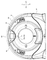
- FIG. 2 is a front view of the X-ray CT apparatus
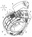
- FIG. 3 is a perspective view when the X-ray CT apparatus is viewed obliquely from the rear.
- the parts of the gantry 11 arranged at the front, rear, both sides, upper and lower sides of the annular rotator 12 may be referred to as a front part, a rear part, a side part, a ceiling part, and a bottom part.
- the left-right direction (both sides), the up-down direction (height direction), and the body axis direction (front-rear direction) may be referred to as an X-axis direction, a Y-axis direction, and a Z-axis direction.
- the rear surface portion of the gantry 11 may be referred to as a frame 13.
- the front and rear of the annular rotator 12 are indicated by Z1 and Z2, and the right and left sides of the annular rotator 12 are indicated by X1 and X2.
- the upper and lower parts are indicated by Y1 and Y2.
- the cover 16 includes a bottom cover 161 that covers the bottom of the gantry 11, a front cover 162 that covers the front surface of the gantry 11, a rear cover 163 that covers the rear surface of the gantry 11, and a gantry 11 has a ceiling cover 164 that covers the ceiling portion of 11, and a side surface cover 165 that covers the side surface portion of the gantry 11.
- the front cover 162 has a tube opening front portion 162a.
- the tube opening front portion 162a is formed in a cylindrical shape, and is fitted into the opening portion 15 from the front so as to cover a substantially front half of the opening portion 15 from the Z-axis direction (body axis direction).
- the rear cover 163 has a tube port rear part 163a.
- the tube mouth rear portion 163a is formed in a cylindrical shape, and is fitted into the opening portion 15 from the rear so as to cover the substantially rear half of the opening portion 15 from the Z-axis direction.
- a tube side portion is configured by the tube port front portion 162a and the tube port rear portion 163a.
- An exhaust port 163b for releasing heat from the radiator 26 described later to the outside of the cover 16 is provided on the upper portion of the rear cover 163.
- the exhaust port 163b is provided at the 12 o'clock position shown in FIGS. Since the heat from the radiator 26 rises inside the cover 16, it is possible to efficiently release the heat from the exhaust port 163 b provided in the upper part of the rear cover 163. Noise from the inside of the cover 16 transmitted to the front side of the X-ray CT apparatus through the exhaust port 163b is reduced as compared with the case where the exhaust port 163b is provided in front portions of the front cover 162 and the bottom cover 161.
- the exhaust port 163b may be provided on the upper portion of the cover 16.
- the exhaust port 163b may be provided in the ceiling cover 164.
- a part of the duct 50 described later is covered with a rear cover 163. Further, the other portions of the fan 41 and the duct 50 to be described later are covered with a side cover 165. Note that other portions of the fan 41 and the duct 50 may be covered with another cover 16, for example, a ceiling cover 164.
- the cooling means 40 has a fan 41.
- the fan 41 is disposed in the vicinity of the radiator 26 and sends out heat from the radiator 26 to the duct 50.
- the duct 50 is disposed between the gantry 11 and the cover 16 and receives exhaust from the fan 41 and guides it to the exhaust port 163b.
- the noise from the inside of the cover includes wind noise when the fan 41 is rotating and the sound of the motor that drives the wind noise.
- FIG. 4 is a cross-sectional view of a soundproof structure constituted by one soundproof member.
- FIG. 4 shows a cross-sectional view when the opening 15 is cut along the body axis direction (Z-axis direction).
- an X-ray transmission port S1 for passing X-rays is formed between the rear end portion 162d of the front end portion 162a of the front cover 162 and the front end portion 163d of the rear end portion 163a of the rear cover 163.
- the width in the circumferential direction of the X-ray transmission port S1 is a size corresponding to the fan angle of the beam X-ray.
- the width of the X-ray transmission port S1 in the Z-axis direction is a size corresponding to the cone angle of the beam X-ray.
- the X-ray transmission port S ⁇ b> 1 is blocked by a sheet-like soundproof member 61. Accordingly, it is possible to ensure safety so that the subject P does not touch the annular rotating body 12. Furthermore, it becomes possible to prevent blood and contrast medium from entering the annular rotator 12. Furthermore, it is possible to prevent noise from the inside of the cover 16 from leaking to the outside.
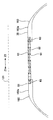
- FIG. 5 is a diagram showing the relationship between the thickness of the soundproof member and the sound transmission loss value.
- the sound transmission loss value is an amount obtained by multiplying the logarithm of the reciprocal of the sound transmittance by 10 and is expressed in decibel [dB].
- the sound transmittance is the ratio of the intensity of transmitted sound to the intensity of incident sound.
- the horizontal axis indicates the thickness [mm] of the soundproof member, and the vertical axis indicates the frequency [Hz] at which the coincidence effect occurs and the sound transmission loss value.
- the coincidence effect refers to a phenomenon in which the sound transmission loss value decreases at a specific frequency.
- the frequency at which the coincidence effect occurs with respect to the thickness T of the soundproof member 61 when the soundproof layer 62 is not provided is indicated by a solid line
- the coincidence effect with respect to the thickness T of the soundproof member 61 when the soundproof layer 62 is provided is indicated by a one-dot chain line
- the sound transmission loss value with respect to the thickness T of the soundproof member 61 is indicated by a broken line.
- the thickness T of the soundproof member 61 As the thickness T of the soundproof member 61 is increased, the sound transmission loss value is increased and the sound insulation is improved. Further, when the thickness T of the soundproof member 61 is increased, the frequency at which the coincidence effect occurs shifts to the low sound side. When the thickness T is t1, the frequency is indicated by f1 in FIG. However, depending on the frequency characteristics of noise, increasing the thickness T does not necessarily lead to an improvement in sound insulation. For example, when the frequency f1 is included in the noise, a coincidence effect occurs, the sound transmission loss value decreases, and the sound insulation performance decreases. Therefore, it is necessary to make the thickness T of the soundproof member 61 thinner than the upper limit value t1 (T ⁇ t1).
- the soundproof structure constituted by one soundproof member 61 has been described above. And it turned out that it is difficult to improve the sound insulation performance using one soundproof member 61.
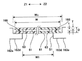
- FIG. 6 is a cross-sectional view of a soundproof structure provided with a soundproof layer.
- FIG. 6 shows a cross-sectional view when the opening 15 is cut along the body axis direction (Z-axis direction).
- the soundproof structure according to this embodiment has two soundproof members 61 and a soundproof layer 62.
- the soundproof layer 62 is composed of an air layer. Two or more combinations of the two soundproof members 61 and the soundproof layer 62 may be provided. Furthermore, the soundproof layer 62 may be configured by a sound absorbing member and / or an acoustic reflecting member.
- FIG. 7 is a partially enlarged sectional view of the soundproof member.
- two soundproof members 61 are arranged so as to sandwich an air layer as the soundproof layer 62.
- the two soundproof members 61 are provided so as to be bridged over the X-ray transmission port S1.
- 6 and 7 show the two soundproof members 61 arranged in parallel.
- the present invention is not limited to this, and the two soundproof members 61 may be arranged at a predetermined angle.
- the soundproof member 61 is a material having a large sound transmission loss, and is made of a thin film material having a high transmittance with respect to the laser for X-rays and marking. Thereby, it is possible to suppress a decrease in image quality of an image acquired by X-ray imaging.
- the kind of the soundproof member 61 includes a sound absorbing member that converts a part of sound energy into heat energy and reduces reflected sound, and an acoustic reflecting member that has a property of reflecting and refracting incident sound.
- sound-absorbing members are fibrous or sponge-like ones with many small holes, and porous materials such as glass wool and urethane are used as representative examples of materials used for sound-absorbing members. Is preferred.
- the acoustic reflecting member may be configured by enclosing a gas, such as helium, having a higher sound speed than air, between the two soundproofing members.
- a gas such as helium
- PET polyethylene terephthalate
- Mylar registered trademark
- the resin material used for the soundproof member 61 is not limited to PET, and may be any material that has high transmittance for X-rays and laser light and low X-ray deterioration resistance.
- the thickness of the soundproof member 61 is preferably 0.5 [mm] to 1.0 [mm].
- the reason why the lower limit of 0.5 [mm] is provided is that even if the subject P touches the soundproof member 61 having the thickness, if the thickness is 0.5 [mm] or more, safety is improved. It can be secured.
- the reason why the upper limit of 1.0 [mm] is provided is that the transparency of X-rays and laser light can be ensured if the thickness is 1.0 [mm] or less.
- the thickness exceeds 1.0 [mm] X-rays and laser light are absorbed. When X-rays are absorbed, image quality is deteriorated. When laser light is absorbed, It becomes a factor that the ease when visually recognizing the mark is lost.
- the soundproof member 61 may be formed of a colorless and transparent film.
- the “film” includes a sheet (hereinafter the same).
- the soundproof member 61 may be made of a colored film that transmits colored laser light.
- the color of the film corresponds to the color of the laser light.
- a red film is used for a red laser
- a green film is used for a green laser.
- the soundproof member 61 is composed of a single colored film.
- the soundproof member 61 may be composed of a composite of a colored film and a colorless transparent film.
- the colorless and transparent film is formed from a colorless and transparent resin.
- the colored film is formed by coloring a colorless and transparent resin.
- Coloring agents such as pigments and dyes are used for resin coloring.
- the pigment an inorganic pigment or an organic pigment is used.
- the dye is selected from the aspect of compatibility with the resin. A dye is dissolved or dispersed in water, a solvent, oil or the like, and exhibits a hue by absorbing visible light. The dye is dispersed in a molecular form and is suitable for coloring transparent resins.
- the air layer As described above, the air layer as the soundproof layer 62 is sandwiched between the two soundproof members 61.
- the air layer may be formed by bonding the two soundproof members 61 with a double-sided tape 63 having a thickness of 0.5 [mm] to 1.0 [mm].
- the frequency at which the coincidence effect occurs is reduced.
- the frequency lowered by providing the air layer is indicated by f2 in FIG.
- the upper limit value of the thickness T of the soundproof member 61 with respect to the frequency f2 is indicated by t2.
- the thickness T of the soundproof member 61 is increased (T ⁇ t2), the sound transmittance loss value is increased, and the sound insulation property is increased. It becomes possible to improve.
- the step part 166 is formed in the rear-end part 162d of the cylinder port front part 162a. Further, a step portion 166 is formed at the front end portion 163d of the tube mouth rear portion 163a.
- the thickness of the air layer may be changed by changing the thickness of the double-sided tape 63. As a result, the frequency is reduced to a predetermined frequency or less where the coincidence effect occurs. Further, the two soundproof members 61 may be arranged at a predetermined angle. At this time, the plate thickness of the double-sided tape 63 may be different between the rear end portion 162d side of the front end portion 162a of the tube mouth and the front end portion 163d side of the rear end portion 163a of the tube mouth.
- step portion 166 First, an adhesive is applied to the step portion 166. Next, one soundproof member 61 is attached to the step portion 166 with the adhesive.
- a double-sided tape 63 is attached to the one soundproof member 61.
- a second soundproof member 61 is attached to the double-sided tape 63.
- the X-ray transmission port S1 can be blocked by the soundproof member 61. Further, by using the double-sided tape 63, it is possible to easily attach the two soundproof members 61 and improve workability.
- the two soundproof members 61 bonded by the double-sided tape 63 may be bonded to the step portion 166.
- the double-sided tape 63 may be attached to the stepped portion 166 and the first soundproof member 61 may be attached to the double-sided tape 63.
- FIG. 8 is a cross-sectional view of the elastic member arranged to close the gap S ⁇ b> 2 between the floor surface and the cover 16.
- a gap S ⁇ b> 2 is provided between the installation location (floor surface F) of the X-ray CT apparatus and the lower edge of the bottom cover 161.
- the gap S2 There is variation in the gap S2. Since the variation is caused by the product accuracy and assembly accuracy of the cover 16, it is difficult to eliminate the gap S2. Noise from the inside of the cover 16 leaks to the outside through the gap S2.
- the lower edge of the bottom cover 161 is in contact with the floor surface F, abnormal noise is generated due to vibration during operation.
- the elastic member 65 is formed in a band shape from an elastic material (for example, resin rubber).
- One side edge 651 of the elastic member 65 is attached along the lower edge of the bottom cover 161.
- the elastic member 65 elastically contacts the floor surface F with its restoring force. Thereby, the gap S2 can be eliminated.
- the other side edge 652 of the elastic member 65 is formed so as to bend inward of the bottom cover 161. Since the other side edge 652 of the elastic member 65 is hidden inside the bottom cover 161, the appearance quality can be improved.
- the other side edge 652 of the elastic member 65 is curved in advance so as to bend toward the inside of the bottom cover 161.
- the thickness of the other side edge 652 is thinner than that of the other part including the one side edge 651 so that it can be easily bent.
- a sound absorbing member may be attached to the inner surface of the cover 16.
- a material in which a porous material such as rock wool or glass wool is formed into a high-density plate shape is used.
- a thin film such as polyethylene or vinyl film is preferably used.
- an acoustic reflection member having a property of reflecting and refracting sound incident on the inner surface of the cover 16 may be attached.
Abstract
Description
以上に、X線CT装置の基本的な構成について説明した。
次に、カバー16の詳細について図2及び図3を参照して説明する。図2はX線CT装置の正面図、図3はX線CT装置を斜め後方から見たときの斜視図である。
冷却手段40はファン41を有している。ファン41は、放熱器26の近傍に配置され、放熱器26からの熱をダクト50に送り出すものである。ダクト50は、架台11とカバー16との間に配置され、ファン41からの排気を受けて排気口163bに導くものである。カバー内部からの騒音としては、ファン41が回転しているときの風切り音及びそれを駆動するモータの音が含まれる。
次に、カバー16内部からの騒音を低減するための防音構造について説明する。
先ず、比較例に係る防音構造について図4を参照して説明する。図4は、一つの防音部材により構成された防音構造の断面図である。図4では、開口部15を体軸方向(Z軸方向)に沿って切断したときの断面図を示している。
ここで、防音部材61の厚さと音響透過損失値との関係について図5を参照して説明する。図5は防音部材の厚さと音響透過損失値との関係を示す図である。ここで、音響透過損失値とは、音響透過率の逆数の対数を10倍した量をいい、デシベル[dB]で表される。また、音響透過率とは、入射音の強さに対する透過音の強さの比をいう。
次に、この実施形態に係る防音構造について図6及び図7を参照して説明する。図6は防音層を設けた防音構造の断面図である。図6では開口部15を体軸方向(Z軸方向)に沿って切断したときの断面図を示している。
防音部材61は、音響透過損失の大きな材料であって、X線及びマーキングのためのレーザに対し透過率の良い薄いフィルム状の材料により構成されている。それにより、X線撮影により取得される画像の画質の低下を抑えることが可能となる。
前述したように、防音層62としての空気層は二つの防音部材61により挟まれている。空気層は、0.5[mm]~1.0[mm]の厚さを有する両面テープ63により二つの防音部材61を貼り合わせることにより形成されるようにしてもよい。
D≧2T+t (2)
W0≧W>W1 (3)
次に、弾性部材65について図1、図3及び図8を参照して説明する。図8は、床面とカバー16との間の間隙S2を塞ぐように配置された弾性部材の断面図である。
S1 X線透過口
S2 間隙
10 X線CT装置
11 架台
111 ファン設置部
112 連通口
12 環状回転体
121 体軸
122 通気口
13 フレーム
14 回転機構
15 開口部
16 カバー
161 底カバー
162 前カバー
162a 筒口前部
163 後カバー
163a 筒口後部
163b 排気口
164 天井カバー
164a 接点
165 側面カバー
166 段部
17 X線管球
18 X線検出器
19 データ収集部(DAS)
20 データ伝送部
21 コンソール
22 スリップリング
23 固定部
24 X線制御部
25 架台制御部
26 放熱器
31 前処理部
32 バスライン
33 システム制御部
34 入力部
35 データ記憶部
36 再構成処理部
37 データ処理部
38 表示部
39 高電圧発生部
40 冷却手段
41 ファン
50 ダクト
61 防音部材
62 防音層
63 両面テープ
65 弾性部材
70 寝台
71 天板
Claims (12)
- 中央に寝台を挿入可能な開口部を有し、内部にX線管球が収納された環状回転体と、
筒状に形成され、前記開口部に嵌め込まれることにより、前記開口部の中心側から前記環状回転体を覆う筒側部を有し、前記筒側部に前記X線管球からのX線を透過するX線透過口が形成されたカバーと、
前記X線透過口を塞ぐように配置され、防音層を挟むように設けられたシート状の二つの防音部材と、
を有する
ことを特徴とするX線CT装置。 - 前記防音部材は、ポリエチレンテレフタレートにより形成されていることを特徴とする請求項1に記載のX線CT装置。
- 前記防音層は、空気層であることを特徴とする請求項1に記載のX線CT装置。
- 前記防音部材の厚さは、0.5[mm]から1.0[mm]であることを特徴とする請求項1に記載のX線CT装置。
- 前記寝台に載置される被検体の体表にレーザ光を照射することにより、前記体表に目印を付けるように構成され、
前記防音部材は、有色の前記レーザ光を透過する有色フィルムにより構成されることを特徴とする請求項4に記載のX線CT装置。 - 前記防音部材は、前記有色フィルムと無色透明フィルムとを重ね合わせることにより構成されることを特徴とする請求項5に記載のX線CT装置。
- 前記有色フィルムは、無色透明の基材に、前記有色のレーザ光を透過する着色剤を練り込むことにより形成されることを特徴とする請求項5に記載のX線CT装置。
- 薄膜状の基材の両面に接着剤が塗られた両面テープをさらに有し、
前記両面テープにより二つの防音部材が貼り合わせられることを特徴とする請求項1に記載のX線CT装置。 - 前記両面テープの厚さは、0.5[mm]から1.0[mm]であることを特徴とする請求項8に記載のX線CT装置。
- 前記防音層は、吸音シートにより形成されることを特徴とする請求項1に記載のX線CT装置。
- 前記吸音シートは、グラスウールを含む多孔質材料であることを特徴とする請求項10に記載のX線CT装置。
- 前記防音層は、音響反射材により形成されることを特徴とする請求項1に記載のX線CT装置。
Priority Applications (2)
| Application Number | Priority Date | Filing Date | Title |
|---|---|---|---|
| US14/235,687 US9414793B2 (en) | 2012-02-22 | 2013-02-20 | X-ray CT system |
| CN201380003062.1A CN103796591B (zh) | 2012-02-22 | 2013-02-20 | X射线ct装置 |
Applications Claiming Priority (2)
| Application Number | Priority Date | Filing Date | Title |
|---|---|---|---|
| JP2012036172 | 2012-02-22 | ||
| JP2012-036172 | 2012-02-22 |
Publications (1)
| Publication Number | Publication Date |
|---|---|
| WO2013125602A1 true WO2013125602A1 (ja) | 2013-08-29 |
Family
ID=49005784
Family Applications (1)
| Application Number | Title | Priority Date | Filing Date |
|---|---|---|---|
| PCT/JP2013/054235 WO2013125602A1 (ja) | 2012-02-22 | 2013-02-20 | X線ct装置 |
Country Status (4)
| Country | Link |
|---|---|
| US (1) | US9414793B2 (ja) |
| JP (1) | JP6188347B2 (ja) |
| CN (1) | CN103796591B (ja) |
| WO (1) | WO2013125602A1 (ja) |
Cited By (1)
| Publication number | Priority date | Publication date | Assignee | Title |
|---|---|---|---|---|
| CN104775726A (zh) * | 2015-03-09 | 2015-07-15 | 江苏建筑职业技术学院 | 列管式消声隔声窗 |
Families Citing this family (2)
| Publication number | Priority date | Publication date | Assignee | Title |
|---|---|---|---|---|
| US10791999B2 (en) * | 2014-02-04 | 2020-10-06 | General Electric Company | Interface for gantry and component |
| US11389126B2 (en) * | 2018-10-31 | 2022-07-19 | General Electric Company | Gantry housing, and medical apparatus |
Citations (6)
| Publication number | Priority date | Publication date | Assignee | Title |
|---|---|---|---|---|
| JPS6338438A (ja) * | 1986-07-31 | 1988-02-19 | 株式会社東芝 | X線ct装置 |
| JPH02124139A (ja) * | 1988-11-01 | 1990-05-11 | Toshiba Corp | Mri用磁石装置の製造方法 |
| JPH03162831A (ja) * | 1989-11-22 | 1991-07-12 | Hitachi Ltd | 核磁気共鳴装置 |
| JPH05124308A (ja) * | 1991-11-06 | 1993-05-21 | Brother Ind Ltd | 圧電素子駆動型印字ヘツド |
| JPH1164599A (ja) * | 1997-08-25 | 1999-03-05 | Shimadzu Corp | X線照射装置 |
| JP2010284302A (ja) * | 2009-06-11 | 2010-12-24 | Toshiba Corp | X線ct装置 |
Family Cites Families (17)
| Publication number | Priority date | Publication date | Assignee | Title |
|---|---|---|---|---|
| US3322233A (en) * | 1964-12-03 | 1967-05-30 | Porter Co H K | Sound control product |
| US4881251A (en) | 1986-07-31 | 1989-11-14 | Kabushiki Kaisha Toshiba | Computed tomograph apparatus |
| JPH08257008A (ja) | 1995-03-23 | 1996-10-08 | Hitachi Medical Corp | 磁気共鳴イメージング装置およびその振動・騒音抑制方法 |
| JP2003026453A (ja) * | 2001-07-10 | 2003-01-29 | Naoyoshi Kayama | ペアガラス |
| JP2003290211A (ja) * | 2002-03-29 | 2003-10-14 | Ge Medical Systems Global Technology Co Llc | X線診断システム及び装置 |
| CN100457044C (zh) | 2006-04-28 | 2009-02-04 | 上海西门子医疗器械有限公司 | Ct设备的风冷散热方法及装置 |
| US7465089B2 (en) * | 2007-01-04 | 2008-12-16 | Battle Ronald K | Protective coverings for radiological equipment |
| JP5220374B2 (ja) * | 2007-09-27 | 2013-06-26 | ジーイー・メディカル・システムズ・グローバル・テクノロジー・カンパニー・エルエルシー | X線ct装置 |
| US20090141853A1 (en) * | 2007-11-30 | 2009-06-04 | Veronica Crews | Protective shield for ct scanning machine |
| JP5117959B2 (ja) * | 2008-08-18 | 2013-01-16 | 三菱樹脂株式会社 | 複層ガラス窓 |
| CN101761732B (zh) | 2008-12-24 | 2013-05-08 | 同方威视技术股份有限公司 | 用于噪声源的隔音系统 |
| JP2010227382A (ja) * | 2009-03-27 | 2010-10-14 | Toshiba Corp | X線ct装置 |
| JP2011098070A (ja) * | 2009-11-06 | 2011-05-19 | Asahi Keisoku:Kk | 医療器械装置用バックグランドミュージック装置 |
| JP2011254888A (ja) * | 2010-06-07 | 2011-12-22 | Toshiba Corp | X線ct装置 |
| GB2483266B (en) * | 2010-09-01 | 2013-03-06 | Echo Barrier Ltd | Sound absorbent barrier |
| US8710842B2 (en) * | 2011-03-07 | 2014-04-29 | General Electric Company | Apparatus and method to reduce noise in magnetic resonance imaging systems |
| US20130129104A1 (en) * | 2011-11-17 | 2013-05-23 | Ashutosh Joshi | System and method for acoustic noise mitigation in a computed tomography scanner |
-
2013
- 2013-02-18 JP JP2013028922A patent/JP6188347B2/ja active Active
- 2013-02-20 CN CN201380003062.1A patent/CN103796591B/zh active Active
- 2013-02-20 WO PCT/JP2013/054235 patent/WO2013125602A1/ja active Application Filing
- 2013-02-20 US US14/235,687 patent/US9414793B2/en active Active
Patent Citations (6)
| Publication number | Priority date | Publication date | Assignee | Title |
|---|---|---|---|---|
| JPS6338438A (ja) * | 1986-07-31 | 1988-02-19 | 株式会社東芝 | X線ct装置 |
| JPH02124139A (ja) * | 1988-11-01 | 1990-05-11 | Toshiba Corp | Mri用磁石装置の製造方法 |
| JPH03162831A (ja) * | 1989-11-22 | 1991-07-12 | Hitachi Ltd | 核磁気共鳴装置 |
| JPH05124308A (ja) * | 1991-11-06 | 1993-05-21 | Brother Ind Ltd | 圧電素子駆動型印字ヘツド |
| JPH1164599A (ja) * | 1997-08-25 | 1999-03-05 | Shimadzu Corp | X線照射装置 |
| JP2010284302A (ja) * | 2009-06-11 | 2010-12-24 | Toshiba Corp | X線ct装置 |
Cited By (1)
| Publication number | Priority date | Publication date | Assignee | Title |
|---|---|---|---|---|
| CN104775726A (zh) * | 2015-03-09 | 2015-07-15 | 江苏建筑职业技术学院 | 列管式消声隔声窗 |
Also Published As
| Publication number | Publication date |
|---|---|
| CN103796591B (zh) | 2016-04-20 |
| US9414793B2 (en) | 2016-08-16 |
| JP6188347B2 (ja) | 2017-08-30 |
| CN103796591A (zh) | 2014-05-14 |
| JP2013198731A (ja) | 2013-10-03 |
| US20140169532A1 (en) | 2014-06-19 |
Similar Documents
| Publication | Publication Date | Title |
|---|---|---|
| JP5159965B1 (ja) | X線ct装置 | |
| JP6116930B2 (ja) | X線ct装置 | |
| EP2325626A1 (en) | Apparatus for multi-modal imaging | |
| JP6188347B2 (ja) | X線ct装置 | |
| US9254108B2 (en) | Gantry with bore safety mechanism | |
| US20100177867A1 (en) | Gantry x-ray transmissive element | |
| US20130129104A1 (en) | System and method for acoustic noise mitigation in a computed tomography scanner | |
| US20160183891A1 (en) | Apparatus and method for multi-modal imaging | |
| JP2008224429A (ja) | 放射線検出装置 | |
| JP5984248B2 (ja) | X線ct用の架台装置 | |
| JP2013169393A (ja) | X線ct装置 | |
| JP2011254888A (ja) | X線ct装置 | |
| JP3132672B2 (ja) | 移動形x線装置 | |
| JP2010227382A (ja) | X線ct装置 | |
| US11647971B2 (en) | Lighting arrangement for a medical imaging system | |
| JP2005087366A5 (ja) | ||
| JP2010502981A (ja) | 受容ボリュームのための適合させられた縁部を用いた光トモグラフィ測定 | |
| JP5075456B2 (ja) | X線ct装置 | |
| WO2005102169A3 (de) | Röntgenstrahler und verfahren zur erzeugung und darstellung von röntgenbildern | |
| JP4373529B2 (ja) | Ct装置およびct装置のシールド構造形成方法 | |
| JP6951092B2 (ja) | 放射線検出器、シンチレータアレイ、及びシンチレータアレイの製造方法 | |
| JP2018102925A (ja) | X線コンピュータ断層撮影装置及び架台装置 | |
| JP6800684B2 (ja) | 放射線撮像装置 | |
| CN113456090A (zh) | 具有光源的医疗设备和用于在医疗设备处发出光信号的方法 | |
| JP5851103B2 (ja) | X線ct装置の架台 |
Legal Events
| Date | Code | Title | Description |
|---|---|---|---|
| WWE | Wipo information: entry into national phase |
Ref document number: 201380003062.1 Country of ref document: CN |
|
| 121 | Ep: the epo has been informed by wipo that ep was designated in this application |
Ref document number: 13752057 Country of ref document: EP Kind code of ref document: A1 |
|
| WWE | Wipo information: entry into national phase |
Ref document number: 14235687 Country of ref document: US |
|
| NENP | Non-entry into the national phase |
Ref country code: DE |
|
| 122 | Ep: pct application non-entry in european phase |
Ref document number: 13752057 Country of ref document: EP Kind code of ref document: A1 |