WO2013121675A1 - タイヤ試験装置 - Google Patents
タイヤ試験装置 Download PDFInfo
- Publication number
- WO2013121675A1 WO2013121675A1 PCT/JP2012/082914 JP2012082914W WO2013121675A1 WO 2013121675 A1 WO2013121675 A1 WO 2013121675A1 JP 2012082914 W JP2012082914 W JP 2012082914W WO 2013121675 A1 WO2013121675 A1 WO 2013121675A1
- Authority
- WO
- WIPO (PCT)
- Prior art keywords
- rim
- attachment
- tire
- around
- attached
- Prior art date
- Legal status (The legal status is an assumption and is not a legal conclusion. Google has not performed a legal analysis and makes no representation as to the accuracy of the status listed.)
- Ceased
Links
Images


Classifications
-
- G—PHYSICS
- G01—MEASURING; TESTING
- G01M—TESTING STATIC OR DYNAMIC BALANCE OF MACHINES OR STRUCTURES; TESTING OF STRUCTURES OR APPARATUS, NOT OTHERWISE PROVIDED FOR
- G01M17/00—Testing of vehicles
- G01M17/007—Wheeled or endless-tracked vehicles
- G01M17/02—Tyres
-
- G—PHYSICS
- G01—MEASURING; TESTING
- G01M—TESTING STATIC OR DYNAMIC BALANCE OF MACHINES OR STRUCTURES; TESTING OF STRUCTURES OR APPARATUS, NOT OTHERWISE PROVIDED FOR
- G01M1/00—Testing static or dynamic balance of machines or structures
- G01M1/02—Details of balancing machines or devices
- G01M1/04—Adaptation of bearing support assemblies for receiving the body to be tested
- G01M1/045—Adaptation of bearing support assemblies for receiving the body to be tested the body being a vehicle wheel
-
- B—PERFORMING OPERATIONS; TRANSPORTING
- B60—VEHICLES IN GENERAL
- B60C—VEHICLE TYRES; TYRE INFLATION; TYRE CHANGING; CONNECTING VALVES TO INFLATABLE ELASTIC BODIES IN GENERAL; DEVICES OR ARRANGEMENTS RELATED TO TYRES
- B60C19/00—Tyre parts or constructions not otherwise provided for
-
- B—PERFORMING OPERATIONS; TRANSPORTING
- B60—VEHICLES IN GENERAL
- B60C—VEHICLE TYRES; TYRE INFLATION; TYRE CHANGING; CONNECTING VALVES TO INFLATABLE ELASTIC BODIES IN GENERAL; DEVICES OR ARRANGEMENTS RELATED TO TYRES
- B60C99/00—Subject matter not provided for in other groups of this subclass
-
- G—PHYSICS
- G01—MEASURING; TESTING
- G01M—TESTING STATIC OR DYNAMIC BALANCE OF MACHINES OR STRUCTURES; TESTING OF STRUCTURES OR APPARATUS, NOT OTHERWISE PROVIDED FOR
- G01M17/00—Testing of vehicles
- G01M17/007—Wheeled or endless-tracked vehicles
- G01M17/02—Tyres
- G01M17/021—Tyre supporting devices, e.g. chucks
-
- G—PHYSICS
- G01—MEASURING; TESTING
- G01M—TESTING STATIC OR DYNAMIC BALANCE OF MACHINES OR STRUCTURES; TESTING OF STRUCTURES OR APPARATUS, NOT OTHERWISE PROVIDED FOR
- G01M1/00—Testing static or dynamic balance of machines or structures
- G01M1/14—Determining imbalance
Definitions
- the present invention relates to a tire testing apparatus.
- This application claims priority based on Japanese Patent Application No. 2012-032779 for which it applied to Japan on February 17, 2012, and uses the content here.
- Tire test apparatuses include a tire uniformity measuring apparatus that measures tire uniformity and a tire balance measuring apparatus that measures tire balance.
- the rim assembly for mounting the tire to be tested is replaced for each type of tire according to the bead diameter and bead width.
- a rim assembly is used in combination of a lower rim (first rim) and an upper rim (second rim) that are detachable from each other.
- Each of the lower rim and the upper rim is formed in a substantially cylindrical shape or a substantially disk shape.
- Patent Documents 1 to 3 disclose inventions related to a rim exchanging device.
- a so-called bayonet type joint may be used to connect the lower rim and the upper rim.
- This joint part is comprised by the nail
- claw pin
- projection part projection part
- the tip of the nail engages with the receiving part, and the rims are connected.
- the lower rim is suspended from the upper rim by the joint portion, so the lower rim is moved together with the upper rim. be able to.
- the rims may be indirectly fixed by fixing the first attachment part to which the lower rim is attached and the second attachment part to which the upper rim is attached by the fixing part.
- the fixing by the fixing portion is released, and one of the lower rim and the upper rim is rotated around the axis of the rim assembly so that the receiving portion does not face the claw. Then, after the rims are brought close to each other, the lower rim and the upper rim are rotated relative to each other around the axis to engage the claw with the receiving portion.
- the present invention provides a tire testing device that prevents the second rim from rotating together with the first rim when the first rim is rotated around the axis while the fixing by the fixing portion is released.
- the purpose is to do.
- a first embodiment of a tire testing device is provided on a second reference surface, a first rim having a pin standing from a first reference surface and having a groove formed around its outer peripheral surface. And a second rim having a projecting portion engageable with the groove portion, and the first and second rims are relative to each other with the second reference surface facing the first reference surface.
- the tire testing apparatus is configured to test a tire attached to the rim assembly by detaching the rim assembly in which the protruding portion is engaged with the groove portion by being rotated.
- the tire test apparatus includes: a first attachment portion that holds the first rim; and the second reference surface of the first rim attached to the first attachment portion with respect to the first reference surface.
- a second attachment portion that holds the second rim so that the reference surfaces face each other, and the first attachment portion is the first attachment portion of the first rim attached to the first attachment portion.
- a rotating portion that rotates about a reference axis perpendicular to the reference plane; a fixing portion that fixes the first mounting portion and the second mounting portion to each other and can release the fixing; and the first mounting portion.
- An attachment moving part that adjusts the distance between the first attachment part and the second attachment part in the direction along the reference axis, and the second attachment part is restricted from rotating around the reference axis and the restriction can be released. Rotation control part.
- a first rim having a projecting portion provided on a first reference surface, and the projecting around an outer peripheral surface of the first rim standing from the second reference surface.
- a second rim having a pin formed with a groove part engageable with the part, wherein the first and second rims face the second reference surface to the first reference surface
- a rim assembly in which the protruding portion is engaged with the groove portion by being rotated relative to the rim assembly so as to be detachable, and a tire testing apparatus for testing a tire attached to the rim assembly.
- the tire test apparatus includes: a first attachment portion that holds the first rim; and the second reference surface of the first rim attached to the first attachment portion with respect to the first reference surface.
- a second attachment portion that holds the second rim so that the reference surfaces face each other, and the first attachment portion is the first attachment portion of the first rim attached to the first attachment portion.
- a rotating portion that rotates about a reference axis perpendicular to the reference plane; a fixing portion that fixes the first mounting portion and the second mounting portion to each other and can release the fixing; and the first mounting portion.
- An attachment moving part that adjusts the distance between the first attachment part and the second attachment part in the direction along the reference axis, and the second attachment part is restricted from rotating around the reference axis and the restriction can be released. Rotation control part.
- the first rim is attached to the first attachment portion, and the second rim is attached to the second attachment portion.
- the mounting portions can be fixed to each other by the fixing portion in a state where the first reference surface and the second reference surface are opposed to each other.
- the fixing by the fixing part is released, the first attaching part is rotated around the reference axis by the rotating part in a state where the rotation restricting part restricts the second attaching part from rotating around the reference axis. Accordingly, the first rim attached to the first attachment portion can be rotated around the reference axis while fixing the second rim attached to the second attachment portion.
- a 1st attachment part and a 2nd attachment part are brought close by an attachment movement part.
- the protrusion can be engaged with the groove portion, and the first rim can be attached to the second rim.
- the rotation restricting portion includes an engaging portion provided in the second attaching portion, and the engaging portion. It is more preferable to have an engaged portion that can be engaged in the circumferential direction and an engagement moving portion that moves the engaged portion forward and backward with respect to the engaging portion.
- the second mounting portion can freely rotate around the reference axis by retracting the engaged portion from the engaging portion by the engaging moving portion.
- a first detection unit that detects a position around the reference axis of the first attachment unit; It is more preferable to include a second detection unit that detects a position of the second attachment unit around the reference axis.
- the first rim and the second rim are integrated when the first mounting portion is rotated around the reference axis by the rotating portion while the mounting portions are fixed to each other by the fixing portion.
- the second detector can detect the positions of the first rim and the second rim around the reference axis.
- the second rim when the first rim is rotated around the axis while the fixing by the fixing portion is released, the second rim is prevented from rotating together with the first rim. can do.
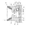
- FIG. 10 is a cross-sectional view taken along a cutting line A1-A1 in FIG.
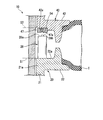
- FIG. 9 is a cross-sectional view taken along a cutting line A2-A2 in FIG. It is sectional drawing for demonstrating the state which lifted the upper rim
- FIG. 17 is a diagram schematically showing a cross section taken along section line A3-A3 in FIG. It is a figure explaining the operation
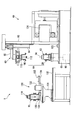
- tire testing apparatus is a tire uniformity measuring apparatus (hereinafter abbreviated as “tire measuring apparatus”) will be described.
- a rim assembly 10 to which a tire to be tested is attached can be attached and detached.
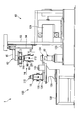
- the tire measuring apparatus 1 includes a main body unit 60 that performs measurement by rotating the mounted rim assembly 10 around its axis, a rim replacement unit 130 that replaces the rim assembly 10 mounted on the main body unit 60, And a control unit (not shown) that controls the main body unit 60 and the rim replacement unit 130.
- the tire measuring device 1 includes various types of rim assemblies 10 having different outer diameters according to the type of tire to be measured. Hereinafter, one type of rim assembly 10 will be described.
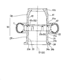
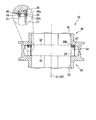
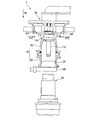
- FIG. 2 is a cross-sectional view showing a state of the rim assembly 10 attached to the lower spindle 62 of the main unit 60.
- the rim assembly 10 includes a lower rim (first rim) 20 and an upper rim (second rim) 40. Both the rims 20 and 40 are engaged with each other in a state where the first reference surface S1 set on the lower rim 20 and the second reference surface S2 set on the upper rim 40 face each other. Can be canceled.
- the lower rim 20 includes a main body 21 formed in a cylindrical shape and a flange portion 22 provided on the outer peripheral surface of the upper end portion 21 a of the main body 21.
- the first reference surface S ⁇ b> 1 is formed on the main surface 22 a on the opposite side of the lower end portion 21 b of the main body 21 in the flange portion 22.
- the first reference plane S1 is formed to be orthogonal to the axis (reference axis) C1 of the lower rim 20.
- the main body 21 is formed with a lower through hole 23 extending so as to be orthogonal to the first reference plane S1.
- a rim-side inclined surface 23a that increases in diameter as being separated from the end portion 21a is formed.
- the rim-side inclined surface 23a is formed in the shape of the side surface of the truncated cone.
- a second flange 24 is provided on the outer peripheral surface of the lower end 21 b of the main body 21.
- a positioning hole 24b is formed in the main surface 24a of the second flange 24 opposite to the flange 22.
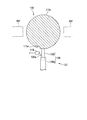
- a pin 27 and a stand 28 are erected on the main surface 22a of the flange portion 22.
- the three pins 27 and the three stands 28 are alternately arranged around the axis C ⁇ b> 1 of the lower rim 20 at equal angles.
- the pin 27 is formed in a substantially cylindrical shape.
- a groove portion 29 is formed over the entire outer peripheral surface.
- the side surface 29a on the distal end side and the side surface 29b on the proximal end side of the groove portion 29 are formed so as to be parallel to the main surface 22a.
- a tip end side of the groove portion 29 in the pin 27 is a tapered projection portion 30 whose diameter is reduced toward the tip end.
- the stand 28 is formed in a columnar shape.
- the front end surface 28a of the stand 28 is provided with a substantially hemispherical projection 28b protruding from the front end surface 28a.
- the tire T to be tested is attached to the edge side of the main surface 22a of the flange portion 22 from the portion where the pin 27 and the stand 28 are provided.
- the upper rim 40 includes a main body 41 formed in a substantially cylindrical shape, and a flange 42 provided on the outer peripheral surface of the lower end portion 41 a of the main body 41.
- the second reference surface S2 is formed on the main surface 42a opposite to the upper end portion 41b of the main body 41 in the flange portion 22.
- the main body 41 is formed with an upper through hole 43 extending so as to be orthogonal to the second reference plane S2.
- a pin receiving portion 46 and a stand receiving portion 47 are provided on the main surface 42 a of the collar portion 42.
- the three pin receiving portions 46 and the three stand receiving portions 47 are alternately arranged around the axis C2 of the upper rim 40 at equal angles.
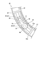
- the pin receiving portion 46 is formed with an insertion opening 48 and a slide opening 49.
- the insertion opening 48 and the slide opening 49 communicate with each other.
- the protrusion 30 of the pin 27 can enter and exit from the insertion opening 48.
- the slide opening 49 is formed in a part of the insertion opening 48 and opens along the circumferential direction of the upper rim 40.
- the width of the slide opening 49 is narrower than the outer diameter of the protrusion 30 of the pin 27 and wider than the outer diameter of the groove 29.
- the slide opening 49 is arranged in a counterclockwise direction with respect to the insertion opening 48.
- the pin receiving portion 46 includes a pair of wall portions 50 erected so as to face each other from the main surface 42 a, and tip portions of the wall portions 50 facing from the tip portions of the respective wall portions 50. And a pair of projecting portions 51 provided to extend to the side.
- the above-described sliding opening 49 is formed by a gap between the pair of protrusions 51 extending so as to approach each other.
- Each wall 50 extends along the circumferential direction of the upper rim 40. The interval between the wall portions 50 is wider than the outer diameter of the protruding portion 30 of the pin 27. The distance from the main surface 42 a to the protrusion 51 is longer than the length of the protrusion 30.
- the thickness dimension of the protrusion 51 is set to be shorter than the distance between the side surfaces 29 a and 29 b of the groove 29.
- the protruding portion 51 is formed so as to be separated from any of the side surfaces 29 a and 29 b when the protruding portion 51 is disposed in the groove portion 29.
- a concave groove 51a formed in a concave shape capable of accommodating the protruding portion 30 of the pin 27 is formed.
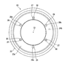
- the stand receiving portion 47 is formed in an arc shape along the circumferential direction of the upper rim 40 in the bottom view. In other words, the stand receiving portion 47 is formed so as to extend around the axis C2. As shown in FIG. 4, the front end surface 47a of the stand receiving portion 47 is formed to be parallel to the main surface 42a. As shown in FIGS. 4 and 6, a concave portion 54 is formed in each of the tip surfaces 47 a. The recess 54 can be engaged with the protrusion 28 b of the stand 28 when the tip surface 28 a of the stand 28 comes into contact with the tip surface 47 a of the stand receiving portion 47. The recessed part 54 is formed in the shape dented conically from the front end surface 47a (refer FIG. 4). As shown in FIGS. 9 and 10, the concave portion 54 is provided at a position facing the protruding portion 28 b of the stand 28 when the protruding portion 51 is disposed in the groove portion 29.
- the engaged state of the rim assembly 10 will be described.
- the lower rim 20 is disposed on the floor or the like.
- An upper rim 40 engaged with the lower rim 20 is disposed on the lower rim 20.
- the pin 27 and the pin receiving portion 46 are engaged.
- the stand 28 and the stand receiving portion 47 are brought into contact with or separated from each other depending on the engagement state of the pin 27 and the pin receiving portion 46.
- FIGS. 8 and 11 A procedure for engaging the lower rim 20 and the upper rim 40 from a state in which the lower rim 20 and the upper rim 40 are separated will be described.
- the upper rim 40 is disposed above the lower rim 20 so that the reference surfaces S ⁇ b> 1 and S ⁇ b> 2 face each other.
- the protrusion 30 of the pin 27 is inserted into the insertion opening 48.
- the stand receiving portion 47 is slightly separated from the stand 28 without being brought into contact with the stand 28. From this state, by rotating the lower rim 20 around the axis C1 with respect to the upper rim 40 while maintaining the distance between the reference surfaces S1 and S2, as shown in FIG. 9 and FIG.
- the protruding portion 51 of the pin receiving portion 46 is disposed.
- the positions (phases) of the recesses 54 and the protrusions 28b match in plan view, the distance between the reference surfaces S1 and S2 is reduced, and the stand receiver 47 is brought into contact with the stand 28. 28b is engaged. At this time, the protrusion 51 is separated from the side surfaces 29 a and 29 b of the groove 29.
- both rims 20, 40 can be fixed by a fixing mechanism 76.
- the lower side is a large diameter part 67b having a constant inner diameter
- the upper side is a small diameter part 67c having a smaller inner diameter than the large diameter part 67b.
- the small diameter portion 67c is formed so that the inner diameter becomes smaller toward the upper side.
- the apparatus-side inclined surface 68a is formed in the shape of the outer surface of the truncated cone having the axis C4 of the lower spindle 62 as the central axis.
- the angle formed between the axis C4 and the apparatus-side inclined surface 68a is set equal to the angle formed between the axis C1 of the lower rim 20 and the rim-side inclined surface 23a.
- the expanded diameter portion 69 is formed with a vent hole 69a communicating with the large diameter portion 67b.
- the vent hole 69a is connected to the air supply source 73, and can supply compressed air into the large diameter portion 67b through the vent hole 69a.
- the air supplied into the large diameter portion 67b is discharged to the outside through the tire hole.
- On the upper surface of the enlarged diameter portion 69 a positioning convex portion 69b that engages with the positioning hole portion 24b is formed.
- FIG. 13 A state where the lower rim 20 is attached to the lower spindle 62 will be described.
- the lower rim 20 is lowered while inserting the lower through hole 23 of the lower rim 20 into the lower spindle 62 and adjusting the direction around the axis C ⁇ b> 1 of the lower rim 20.
- the positioning hole 24b is engaged with the positioning convex portion 69b and the rim side inclined surface 23a of the lower rim 20 is brought into contact with the apparatus side inclined surface 68a of the lower spindle 62, the rim side inclined surface 23a is brought into contact with the apparatus side inclined surface 68a. Makes surface contact.
- the position (phase) around the axis C1 of the lower rim 20 with respect to the lower spindle 62 becomes constant.
- the lower rim 20 can be attached to and detached from the lower spindle 62.
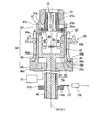
- the lower spindle 62 incorporates a fixing mechanism (fixing part) 76.
- the fixing mechanism 76 is a known fixing mechanism described in, for example, Japanese Patent No. 3040514.
- the fixing mechanism 76 includes a tapered sleeve 77 and a hook operation rod 78 connected to the tapered sleeve 77 as main components.
- the taper sleeve 77 has a main body 79 formed in a substantially truncated cone shape, and a flange portion 80 provided on the outer peripheral surface of the lower end of the main body 79.
- a through hole 79a is formed in the main body 79 in the direction of the axis C4.
- the side wall 79b of the main body 79 is formed with a plurality of slits 79c that penetrate the side wall 79b in the thickness direction and extend along the axis C4 of the main body 79.
- the taper sleeve 77 receives the force compressed in the radial direction, whereby the width of the slit 79c is narrowed, and the inner diameter of the through hole 79a can be reduced.
- the hook operation rod 78 has a cylindrical portion 83 formed in a bottomed cylindrical shape, and a shaft-shaped member 84 that is fixed to the bottom surface of the cylindrical portion 83 and extends downward.
- An annular groove 83 a that engages with the flange portion 80 of the taper sleeve 77 is formed at the upper end of the inner peripheral surface of the cylindrical portion 83.
- the cylindrical portion 83 is formed with a pair of long holes 83b penetrating through the wall portion and having a major axis in the vertical direction.
- the lower proximity sensor 118 can detect the position of the lower spindle 62 around the axis C ⁇ b> 1 by detecting whether or not the metal detector 117 has approached itself.
- the lower proximity sensor 118 is fixed to the base 61, for example.
- the lower proximity sensor 118 transmits a signal to the control unit when the metal detector 117 is detected.
- the aforementioned cylinder can move the hook operating rod 78 up and down.
- a pair of hooks 87 are arranged in the cylindrical portion 83 so as to face each other with the axis C ⁇ b> 4 interposed therebetween. Both ends of the pin 88 serving as a fulcrum of the hook 87 are fixed to the lower spindle 62 through the long hole 83 b of the cylindrical portion 83.
- a spring 89 is connected to the lower end portion of each hook 87 and urges the lower end portions of the hooks 87 to approach each other.
- An engaging claw 87a projects from a portion of the upper end portion of the hook 87 facing the axis C4.
- the hook operation rod 78 of the fixing mechanism 76 moves downward with respect to the lower spindle 62.
- a slight gap is formed between the outer peripheral surface of the tapered sleeve 77 in the natural state and the small diameter portion 67 c of the cylindrical portion 67.
- the upper end portion of the hook 87 enters the notch 83c formed in the inner peripheral surface of the cylindrical portion 83, and the distance between the engaging claws 87a is the upper rim shaft described later.
- the outer diameter of 112 is larger.
- the hook operating rod 78 of the fixing mechanism 76 has moved upward.
- the lower spindle 62 is supported on the base 61 by a bearing (not shown).
- the lower spindle 62 can be rotated around the axis C4 by a servo motor (rotating unit) 90 shown in FIG.
- the elevating mechanism 63 has a frame 93 fixed to the base 61 and a rim elevator (attachment moving part) 95 attached to the frame 93 via a ball screw 94.
- the rim elevator 95 can be moved in the vertical direction by a ball screw 94, and the vertical distance between the lower spindle 62 and a connection adapter 110 (described later) attached to the rim elevator 95 can be adjusted.
- the rim elevator 95 has a positioning portion 96 and a chuck portion 97.
- the positioning portion 96 includes a rod 101 inserted through a through hole 100a formed in the support plate 100, a substantially disc-shaped positioning member 102 fixed to the lower end of the rod 101, and a support member fixed to the upper end of the rod 101. 103.
- On the lower surface of the positioning member 102 a second device-side inclined surface 102a that increases in diameter as it goes downward is formed.
- the springs 104 through which the rods 101 are inserted are respectively locked to the lower surface of the support plate 100 and the upper surface of the positioning member 102, and the support plate 100 and the positioning member 102 are mutually connected regardless of the distance between the support plate 100 and the positioning member 102. A force that tries to separate them is generated.
- the outer diameter of the support member 103 is set larger than the outer diameter of the through hole 100a.
- the support member 103 is locked to the upper surface of the support plate 100.
- the chuck portion 97 includes a gripping air cylinder 106 and a pair of gripping members 107 attached to the gripping air cylinder 106 and slidable in a direction parallel to the horizontal plane.
- the support plate 100 is provided with a known upper proximity sensor (second detection unit) 119. Similar to the lower proximity sensor 118 described above, the upper proximity sensor 119 can detect whether or not a convex portion 111d of the connection adapter 110 described later has approached itself.
- a movable stopper 120 is provided at a position facing the upper proximity sensor 119 of the support plate 100.
- the movable stopper 120 has a known configuration, and the stopper (engaged portion) 120b is attached to the air cylinder 120a by adjusting the pressure of air acting on the air cylinder (engagement moving portion) 120a. Can be advanced or retreated.
- connection adapter 110 includes an adapter main body 111 that is detachably attached to the upper rim 40 with a bolt (not shown) and the like, and an upper rim shaft 112 that is fixed to the lower portion of the adapter main body 111.
- the adapter body 111 and the upper rim shaft 112 are made of metal.
- the adapter main body 111 and the upper rim shaft 112 may be integrally formed, or may be joined after being formed separately.
- the position around the axis C1 of the upper rim 40 with respect to the connection adapter 110 is set to be constant by the bolt described above.
- a second rim-side inclined surface 111 a is formed on the upper portion of the adapter main body 111.
- the second rim-side inclined surface 111a is formed to increase in diameter as it goes downward.
- an engaging groove 111b for engaging the grip member 107 is formed on the outer peripheral surface of the adapter main body 111.
- a disc-like member 111c having a larger diameter than the second rim side inclined surface 111a and the engaging groove 111b is provided.
- a convex part 111d protruding outward in the radial direction and a notch (engaging part) 111e are formed at the edge of the disk-like member 111c.
- the above-described stopper 120b can be engaged with the notch 111e.
- the convex portion 111d and the notch 111e are formed at positions opposite to each other with the center of the disk-shaped member 111c interposed therebetween in plan view.
- the rotation restricting portion 121 includes a notch 111e and the above-described movable stopper 120. As shown in FIG. 17, on the outer peripheral surface of the lower end portion of the upper rim shaft 112, an engagement recess 112a that engages with the engagement claw 87a is formed.
- connection adapter 110 rotates around the axis C1 and the upper proximity sensor 119 detects the convex portion 111d, thereby detecting the position of the connection adapter 110 around the axis C1. it can.
- a signal that the upper proximity sensor 119 detects the convex portion 111d is transmitted to the control unit.
- the control unit advances the stopper 120b by the air cylinder 120a of the movable stopper 120, and engages the stopper 120b with the notch 111e.
- the connection adapter 110 is restricted from rotating around the axis C1 (the circumferential direction of the connection adapter 110).
- the restriction can be released by retracting the stopper 120b by the air cylinder 120a.
- the upper rim 40 attached to the chuck portion 97 via the connection adapter 110 is arranged such that the second reference surface S2 faces the first reference surface S1 of the lower rim 20 attached to the lower spindle 62. Retained.
- connection adapter 110 is fixed to the lower spindle 62 by changing the fixing mechanism 76 from the standby state to the fixed state.
- the taper sleeve 77 moves downward to increase the inner diameter of the through-hole 79a, and the distance between the engagement claws 87a is long and short.
- the fixing mechanism 76 enters a standby state. Thereby, fixation with the connection adapter 110 with respect to the lower spindle 62 can be cancelled
- a load wheel 124 is arranged on a rail 123 in the base 61.
- the road wheel 124 can approach the lower spindle 62 or be separated from the lower spindle 62 by traveling on the rail 123.
- the swivel base 131 can travel on the rail 132 and approach the lower spindle 62 or be separated from the lower spindle 62.
- a swivel shaft 133 is provided on the swivel base 131.
- a plurality of stocker frames 134 are connected to the turning shaft 133.
- the pivot shaft 133 rotates the stocker frame 134 around the axis of the pivot shaft 133.
- the turning shaft 133 can move the rim assembly 10 disposed on the rim pedestal 135 of the stocker frame 134 closer to or away from the lower spindle 62.
- Positioning projections 69b are formed on each stocker frame 134, and the phase around the axis C1 of the rim assembly 10 disposed on the stocker frame 134 is positioned.
- the operation of the tire measuring device 1 will be described.
- the rim assembly 10 attached to the main unit 60 is exchanged, each case where the measurement is performed with the tire T attached to the rim assembly 10 attached to the main unit 60 will be described. These operations are performed based on the control of the control unit.
- FIG. 1 A case where the rim assembly 10 is replaced will be described.
- the lower rim 20 and the upper rim 40 are separated.
- the lower rim 20 is attached to the lower spindle 62, and the connection adapter 110 fixed to the upper rim 40 is attached to the rim elevator 95 and moved upward.
- the fixing mechanism 76 in the lower spindle 62 is in a standby state, and the load wheel 124 and the swivel base 131 are separated from the lower spindle 62.
- the rim elevator 95 is lowered to move the upper rim 40 downward, and the upper rim shaft 112 is inserted into the tapered sleeve 77 of the fixing mechanism 76.
- the phase relationship between the rims 20 and 40 is arbitrary.
- the lower rim 20 and the upper rim 40 are slightly separated so that the pin 27 and the stand 28 do not contact the pin receiving portion 46 and the stand receiving portion 47.
- the hook operating rod 78 is moved upward to fix the fixing mechanism 76, and the lower rim 20 and the upper rim 40 are fixed via the lower spindle 62 and the connection adapter 110 as described above.
- the arrow Y2 when the lower spindle 62 is rotated around the axis C1 by the servo motor 90, both the rims 20 and 40 are rotated together around the axis C1.
- the upper proximity sensor 119 transmits a signal to the control unit when the convex portion 111d is detected.
- the control unit stops the drive by the servo motor 90 and stops the lower spindle 62 and the connection adapter 110.
- the hook operating rod 78 is moved downward to enter a standby state. At this time, the taper sleeve 77 also moves downward.
- the stopper 120b is advanced by the air cylinder 120a of the movable stopper 120, and the stopper 120b is engaged with the notch 111e.
- the lower spindle 62 is rotated around the axis C1 by the servo motor 90. Since the connection adapter 110 to which the upper rim 40 is attached is restricted from rotating by the stopper 120b, only the lower rim 20 rotates about the axis C1.
- the lower proximity sensor 118 transmits a signal to the control unit when the metal detector 117 is detected.
- the control unit stops the drive by the servo motor 90 and stops the rotation of the lower spindle 62.
- the phase relationship between the rims 20 and 40 at this time is such that the pin 27 of the lower rim 20 faces the insertion opening 48 of the upper rim 40 as shown in FIG.
- the rim elevator 95 is lowered to move the upper rim 40 slightly downward, and the protrusion 30 of the pin 27 is inserted into the insertion opening 48 as shown in FIG. At this time, the stand receiving portion 47 is not brought into contact with the stand 28.
- the lower spindle 62 is rotated around the axis C ⁇ b> 1 by the servo motor 90, and the lower rim 20 is moved to a position where the protrusion 28 b of the stand 28 faces the recess 54 of the upper rim 40 as shown in FIG. 9.
- the protruding portion 51 of the upper rim 40 is disposed in the groove portion 29 of the pin 27, the pin receiving portion 46 and the pin 27 are engaged, and the lower rim 20 and the upper rim 40 are integrated.
- the rim elevator 95 is raised, and the rim assembly 10 in which both the rims 20, 40 are integrated is moved upward.
- the pin receiving portion 46 of the upper rim 40 supports the pin 27, and the lower rim 20 is suspended from the upper rim 40.
- the rim replacement unit 130 is moved closer to the lower spindle 62.
- the stocker frame 134 in which the rim assembly 10 is not disposed is disposed below the rim assembly 10 supported by the rim elevator 95.
- the rim elevator 95 is lowered, and the rim assembly 10 to which the connection adapter 110 is attached is arranged on the rim base 135 on the stocker frame 134.
- the positioning hole 24b of the lower rim 20 is engaged with the positioning convex portion 69b protruding on the stocker frame 134.
- the lower rim 20 supports the upper rim 40 in a state where the stand receiving portion 47 abuts the stand 28 and the protrusion 28 b of the lower rim 20 is engaged with the recess 54 of the upper rim 40.
- the pin 27 and the pin receiving portion 46 do not interfere with each other, the pin 27 does not support the load of the upper rim 40, and damage to the pin 27 can be prevented.
- the pair of gripping members 107 supporting the connection adapter 110 are moved away from each other, and the rim elevator 95 is moved.
- the rim assembly 10 is removed.
- the rim elevator 95 is raised and separated from the rim replacement unit 130.
- the stocker frame 134 is rotated around the axis of the pivot shaft 133, so that a rim assembly 10 of a type different from the rim assembly 10 that has been attached to the main unit 60 so far is mounted on the rim elevator. It is located below 95.
- the rim elevator 95 is lowered and the gripping member 107 is moved so as to sandwich the engaging groove 111b of the adapter main body 111.
- the gripping members 107 are brought close to each other, and the gripping members 107 are engaged with the engagement grooves 111b.
- the lower rim 20 and the upper rim 40 of the rim assembly 10 are engaged with each other.
- the rim elevator 95 engaged with the rim assembly 10 is raised.
- the rim replacement unit 130 is separated from the lower spindle 62, and the stocker frame 134 of the rim replacement unit 130 is retracted from above the lower spindle 62.
- the rim elevator 95 is lowered and the rim assembly 10 is attached to the lower spindle 62.
- the lower spindle 62 is inserted into the lower through hole 23 of the lower rim 20 and the upper through hole 43 of the upper rim 40.
- the rim side inclined surface 23a of the lower rim 20 is brought into contact with the apparatus side inclined surface 68a of the lower spindle 62, and the rim assembly 10 is supported by the apparatus side inclined surface 68a.
- the lower rim 20 is rotated with respect to the upper rim 40 by rotating the lower spindle 62 clockwise around the axis C4 in plan view.
- the phase relationship between the upper rim 40 and the lower rim 20 is as shown in FIGS.
- the protrusion 30 of the pin 27 reaches the insertion opening 48 by the clockwise rotation of the lower rim 20.
- the engagement between the pin receiving portion 46 and the pin 27 can be released.
- the pin 27 is separated from the pin receiving portion 46, and the rim assembly 10 can be separated into the lower rim 20 and the upper rim 40 as shown in FIG.
- the tire T is disposed on the flange portion 22 of the lower rim 20 from the state where the tire measuring device 1 is as shown in FIG. 1.
- the rim elevator 95 is lowered to a predetermined tire rim width.
- the upper rim shaft 112 is inserted into the through hole 79 a of the taper sleeve 77 of the fixing mechanism 76 and between the pair of hooks 87.
- the hook operating rod 78 is moved upward to fix the fixing mechanism 76, and the lower spindle 62, the rim assembly 10 and the connection adapter 110 are integrated.
- the lower rim 20 is attached to the lower spindle 62 and the upper rim 40 is attached to the connection adapter 110.
- the tire measuring device 1 can fix the lower spindle 62 and the connection adapter 110 to each other by the fixing mechanism 76 in a state where the first reference surface S1 and the second reference surface S2 are opposed to each other.
- the servo motor 90 causes the lower spindle 62 to move along the axis line while the rotation restriction unit 121 restricts the rotation of the connection adapter 110 around the axis C1. Rotate around C1.
- the tire measuring device 1 fixes the upper rim 40 attached to the connection adapter 110 even when a frictional force or the like acts between the taper sleeve 77 of the fixing mechanism 76 and the connection adapter 110.
- the lower rim 20 attached to the lower spindle 62 can be rotated around the axis C1. Then, the tire measuring device 1 rotates the lower spindle 62 so that the pin 27 faces the insertion opening 48, and then brings the connection adapter 110 closer to the lower spindle 62 by the rim elevator 95.
- the tire measuring device 1 causes the groove portion 29 of the pin 27 to be engaged with the protruding portion 51 of the pin receiving portion 46 by rotating the lower spindle 62 around the axis C ⁇ b> 1 by the servo motor 90, and the lower rim 20 is attached to the upper rim 40. Can be attached.
- the rotation restricting portion 121 includes a notch 111e and a movable stopper 120.
- the tire measuring device 1 allows the connection adapter 110 to freely rotate around the axis C1 by retracting the stopper 120b from the disk-like member 111c by the air cylinder 120a.
- the tire measuring apparatus 1 causes the connection adapter 110 to rotate around the axis C1 by causing the air cylinder 120a to bring the stopper 120b closer to the disk-shaped member 111c and engaging the notch 111e in the circumferential direction of the connection adapter 110. Can be restricted.
- the tire measuring device 1 can easily switch whether or not to restrict the rotation of the connection adapter 110 by adjusting the position of the stopper 120b.
- the tire measuring device 1 can regulate the rotation of the connection adapter 110 around the axis C1 with a simple configuration of the notch 111e and the movable stopper 120, the manufacturing cost of the tire measuring device 1 can be suppressed. Can do.
- the tire measuring device 1 includes a lower proximity sensor 118 and an upper proximity sensor 119.
- the tire measuring device 1 When the tire adapter 1 is rotated around the axis C1 by the servo motor 90 in a state where the lower spindle 62 and the connection adapter 110 are fixed to each other by the fixing mechanism 76, the tire measuring device 1 has the lower rim 20 and the upper rim 40. Can be detected by the upper proximity sensor 119 in a state where the two rims 20 and 40 are around the axis C1.
- the tire measuring device 1 releases the fixing by the fixing mechanism 76 and rotates the lower spindle 62 around the axis C1 by the servo motor 90 in a state where the rotation restricting portion 121 restricts the connection adapter 110 from rotating around the axis C1.
- the position of the lower spindle 62 around the axis C1 can be detected by the lower proximity sensor 118.
- the pin 27 is formed on the lower rim 20 and the pin receiving portion 46 is formed on the upper rim 40.
- the pin receiving portion 46 may be formed on the lower rim, and the pin 27 may be formed on the upper rim. Even if the lower rim and the upper rim are configured in this way, the same effects as those of the above-described embodiment can be obtained.
- the first rim is the lower rim 20 and the second rim is the upper rim 40.
- the first rim may be the upper rim and the second rim may be the lower rim.
- the first attachment portion attached to the upper rim is rotated around the axis by the rotating portion, and the rotation restricting portion restricts the rotation of the second attachment portion attached to the lower rim around the axis. .
- the convex portion 111d detected by the upper proximity sensor 119 is provided in the connection adapter 110.
- a recess 120c may be provided in the stopper 120b instead of the protrusion 111d.
- the recess 120c is made of metal.
- the stopper 120b is constantly urged by the air cylinder 120a.
- the upper proximity sensor 119 does not detect the recess 120c when the tip of the stopper 120b is in contact with the edge of the disc-shaped member 111c, but does not detect the recess 120c when the stopper 120b moves forward when engaged with the notch 111e. It is arranged at the position to detect.
- the control portion retracts the stopper 120b from the disk-like member 111c by the air cylinder 120a.
- the proximity sensor which can detect the metal detection body 117 and the convex part 111d by non-contact was used as a 1st detection part and a 2nd detection part.
- these detection units are not limited to proximity sensors, and non-contact or contact sensors can be appropriately selected and used.
- Usable non-contact type sensors include line sensors and encoders, and contact type sensors include electrical contacts that mechanically switch ON / OFF.
- the lower proximity sensor 118 and The upper proximity sensor 119 may not be provided.
- the tire testing apparatus 1 is a tire uniformity measuring apparatus.
- the tire testing apparatus 1 is not limited to this and may be a tire balance measuring apparatus.
- the present invention relates to a tire testing apparatus that prevents the second rim from rotating together with the first rim when the first rim is rotated around the axis in a state where the fixing by the fixing portion is released.
- Tire measuring device 10 Rim assembly 20 Lower rim (first rim) 27 pin 29 groove 40 upper rim (second rim) 51 Projection 62 Lower spindle (first mounting part) 76 Fixing mechanism (fixing part) 90 Servo motor (rotating part) 95 Rim Elevator (Moving part) 110 Connection adapter (second mounting part) 111e Notch (engagement part) 118 Lower proximity sensor (first detection unit) 119 Upper proximity sensor (second detection unit) 120a Air cylinder (engagement moving part) 120b Stopper (engaged part) 121 Rotation restriction part C1 axis (reference axis) S1 First reference surface S2 Second reference surface T Tire
Landscapes
- Physics & Mathematics (AREA)
- General Physics & Mathematics (AREA)
- Engineering & Computer Science (AREA)
- Mechanical Engineering (AREA)
- Testing Of Balance (AREA)
- Tires In General (AREA)
Priority Applications (5)
| Application Number | Priority Date | Filing Date | Title |
|---|---|---|---|
| KR1020137020053A KR101444630B1 (ko) | 2012-02-17 | 2012-12-19 | 타이어 시험 장치 |
| DE112012005891.7T DE112012005891B4 (de) | 2012-02-17 | 2012-12-19 | Reifentestvorrichtung |
| CN201280006702.XA CN103370609B (zh) | 2012-02-17 | 2012-12-19 | 轮胎试验装置 |
| IN3231DEN2014 IN2014DN03231A (https=) | 2012-02-17 | 2012-12-19 | |
| US13/980,766 US9322734B2 (en) | 2012-02-17 | 2012-12-19 | Tire testing apparatus |
Applications Claiming Priority (2)
| Application Number | Priority Date | Filing Date | Title |
|---|---|---|---|
| JP2012032779A JP5752068B2 (ja) | 2012-02-17 | 2012-02-17 | タイヤ試験装置 |
| JP2012-032779 | 2012-02-17 |
Publications (1)
| Publication Number | Publication Date |
|---|---|
| WO2013121675A1 true WO2013121675A1 (ja) | 2013-08-22 |
Family
ID=48983817
Family Applications (1)
| Application Number | Title | Priority Date | Filing Date |
|---|---|---|---|
| PCT/JP2012/082914 Ceased WO2013121675A1 (ja) | 2012-02-17 | 2012-12-19 | タイヤ試験装置 |
Country Status (8)
| Country | Link |
|---|---|
| US (1) | US9322734B2 (https=) |
| JP (1) | JP5752068B2 (https=) |
| KR (1) | KR101444630B1 (https=) |
| CN (1) | CN103370609B (https=) |
| DE (1) | DE112012005891B4 (https=) |
| IN (1) | IN2014DN03231A (https=) |
| TW (1) | TWI485380B (https=) |
| WO (1) | WO2013121675A1 (https=) |
Families Citing this family (13)
| Publication number | Priority date | Publication date | Assignee | Title |
|---|---|---|---|---|
| KR101482897B1 (ko) * | 2010-12-15 | 2015-01-14 | 가부시키가이샤 고베 세이코쇼 | 타이어 시험 장치 |
| JP5752012B2 (ja) * | 2011-11-11 | 2015-07-22 | 三菱重工マシナリーテクノロジー株式会社 | リム組立体、タイヤ試験機及びリム組立体交換方法 |
| JP5851848B2 (ja) * | 2012-01-12 | 2016-02-03 | 三菱重工マシナリーテクノロジー株式会社 | タイヤ試験装置 |
| JP5752057B2 (ja) * | 2012-01-12 | 2015-07-22 | 三菱重工マシナリーテクノロジー株式会社 | リム組立体およびタイヤ試験装置 |
| US8910512B2 (en) * | 2012-03-22 | 2014-12-16 | Kobe Steel, Ltd. | Multi-component force measurement spindle unit of tire testing machine |
| DE112012005866B4 (de) | 2012-08-06 | 2022-05-12 | Mitsubishi Heavy Industries Machinery Systems, Ltd. | Reifenhaltevorrichtung |
| JP6187889B2 (ja) * | 2015-02-24 | 2017-08-30 | 三菱重工マシナリーテクノロジー株式会社 | タイヤ検査装置、及びタイヤの姿勢検出方法 |
| ES2620974T3 (es) * | 2015-03-12 | 2017-06-30 | Corghi S.P.A. | Máquina de servicio de ruedas y método para bloquear una rueda a una unidad de soporte de ruedas |
| US10414219B2 (en) * | 2015-08-11 | 2019-09-17 | Performance Ag, Llc | Apparatus, systems and methods for tire mounting and inflation |
| KR102109247B1 (ko) * | 2018-01-31 | 2020-05-11 | 동의대학교 산학협력단 | 폼필드타이어용 폼 충진 금형장치 |
| WO2019163016A1 (ja) * | 2018-02-21 | 2019-08-29 | 三菱重工機械システム株式会社 | リム交換装置、タイヤ試験装置、及びリム交換方法 |
| CN111742206B (zh) * | 2018-02-21 | 2022-07-08 | 三菱重工机械系统株式会社 | 轮胎保持机构及轮胎试验装置 |
| CN110031151A (zh) * | 2019-05-27 | 2019-07-19 | 软控股份有限公司 | 一种轮胎动平衡试验机的上轮辋驱动装置 |
Citations (9)
| Publication number | Priority date | Publication date | Assignee | Title |
|---|---|---|---|---|
| JPS6071237A (ja) * | 1983-09-28 | 1985-04-23 | Bridgestone Corp | タイヤの把持装置 |
| JPS62135937U (https=) * | 1986-02-19 | 1987-08-27 | ||
| JPS63232009A (ja) * | 1987-01-14 | 1988-09-28 | ユニローヤル グッドリッチ ライセンシング サービシス,インコーポレイティド | タイヤ均一化機械用リム・スピンドル組立体 |
| JPH02171633A (ja) * | 1988-12-26 | 1990-07-03 | Yokohama Rubber Co Ltd:The | タイヤユニフオミテイーに於ける段取り替え用二つ割りリム |
| JPH03110138A (ja) * | 1989-09-25 | 1991-05-10 | Kobe Steel Ltd | タイヤユニフォミティマシンにおけるリムチエンジャ装置 |
| JPH0970833A (ja) * | 1995-09-04 | 1997-03-18 | Bridgestone Corp | ポストキュアインフレータのリム交換装置 |
| JP3040514B2 (ja) * | 1991-04-09 | 2000-05-15 | 三菱重工業株式会社 | タイヤの動バランス測定機 |
| JP2006051791A (ja) * | 2004-07-16 | 2006-02-23 | Yokohama Rubber Co Ltd:The | タイヤ保持装置 |
| JP2011174839A (ja) * | 2010-02-25 | 2011-09-08 | Mitsubishi Heavy Ind Ltd | タイヤ試験機のリム交換装置及びリム交換方法 |
Family Cites Families (25)
| Publication number | Priority date | Publication date | Assignee | Title |
|---|---|---|---|---|
| US3043130A (en) | 1958-09-22 | 1962-07-10 | Robert E Patterson | Tubeless tire testing apparatus |
| JPS5837966A (ja) | 1981-08-31 | 1983-03-05 | Toshiba Corp | Mos型半導体装置 |
| JPH0347742A (ja) | 1989-04-14 | 1991-02-28 | Kobe Steel Ltd | タイヤユニフォミティマシンのリム交換装置 |
| JP2661753B2 (ja) | 1989-08-30 | 1997-10-08 | 株式会社神戸製鋼所 | タイヤユニフォミティマシン |
| JPH03231834A (ja) | 1990-02-07 | 1991-10-15 | Kobe Steel Ltd | タイヤユニフォミティマシンのリム交換装置 |
| JP2542774B2 (ja) | 1992-08-31 | 1996-10-09 | ジャパン・フィールド株式会社 | 可燃性溶剤を用いた洗浄装置 |
| JP3532263B2 (ja) * | 1994-10-19 | 2004-05-31 | 株式会社ブリヂストン | タイヤユニフォミティマシン用リム装着装置 |
| US6237402B1 (en) * | 1996-04-15 | 2001-05-29 | The Goodyear Tire & Rubber Company | Tire and rim assembly centering method |
| JP3672135B2 (ja) | 1996-08-09 | 2005-07-13 | 株式会社ブリヂストン | タイヤユニフォミティ測定におけるリム交換装置 |
| US5992227A (en) | 1997-01-24 | 1999-11-30 | Jellison; Frank R. | Automatic adjustable width chuck apparatus for tire testing systems |
| EP0924502A3 (en) * | 1997-12-16 | 1999-07-07 | Kokusai Keisokuki Kabushiki Kaisha | Apparatus for measuring uniformity and/or dynamic-balance of tire |
| US6584835B2 (en) * | 2000-02-11 | 2003-07-01 | Mts Systems Corporation | Spindle assembly for a tire or wheel testing machine |
| US6661505B2 (en) | 2001-06-28 | 2003-12-09 | Snap-On Technologies, Inc. | Method and system for measuring caster trail |
| KR20040057963A (ko) | 2002-12-24 | 2004-07-02 | 가부시키가이샤 고베 세이코쇼 | 타이어 유니포미티 기계 |
| US7357170B2 (en) * | 2003-04-09 | 2008-04-15 | Bridgestone Corporation | Split rim for tire, method of assembling a rim/tire assembly, and method and device for installing the rim/tire assembly |
| JP2004360586A (ja) | 2003-06-05 | 2004-12-24 | Mitsubishi Electric Corp | 筒内噴射用燃料噴射弁装置 |
| CN2690875Y (zh) | 2004-01-13 | 2005-04-06 | 中国航空工业第一集团公司北京航空制造工程研究所 | 轮胎动平衡试验机动平衡主轴驱动轮 |
| KR100915492B1 (ko) * | 2004-05-14 | 2009-09-03 | 가부시키가이샤 고베 세이코쇼 | 타이어 시험기 |
| CN2893681Y (zh) | 2005-12-29 | 2007-04-25 | 中国航空工业第一集团公司北京航空制造工程研究所 | 一种轮胎动平衡试验机轮胎定位锁紧装置的轮辋锁定机构 |
| JP4456126B2 (ja) * | 2007-01-16 | 2010-04-28 | 国際計測器株式会社 | タイヤのユニフォーミティ試験装置 |
| CN100501363C (zh) | 2007-02-16 | 2009-06-17 | 天津市橡塑机械研究所有限公司 | 全自动载重轮胎动静平衡/跳动度试验机用轮辋更换装置 |
| CN201225958Y (zh) | 2008-06-12 | 2009-04-22 | 青岛高校软控股份有限公司 | 上轮辋升降机构 |
| WO2010061845A1 (ja) * | 2008-11-28 | 2010-06-03 | 株式会社神戸製鋼所 | タイヤ検査装置のリム装着装置、磁石取付方法、リム交換装置、並びにタイヤ検査装置 |
| TWM418285U (en) | 2011-08-11 | 2011-12-11 | Innova Rubber Co Ltd | Tilt angle and loading adjustment mechanism of wheel testing machine |
| JP5752012B2 (ja) * | 2011-11-11 | 2015-07-22 | 三菱重工マシナリーテクノロジー株式会社 | リム組立体、タイヤ試験機及びリム組立体交換方法 |
-
2012
- 2012-02-17 JP JP2012032779A patent/JP5752068B2/ja not_active Expired - Fee Related
- 2012-12-19 WO PCT/JP2012/082914 patent/WO2013121675A1/ja not_active Ceased
- 2012-12-19 DE DE112012005891.7T patent/DE112012005891B4/de not_active Expired - Fee Related
- 2012-12-19 US US13/980,766 patent/US9322734B2/en active Active
- 2012-12-19 KR KR1020137020053A patent/KR101444630B1/ko not_active Expired - Fee Related
- 2012-12-19 CN CN201280006702.XA patent/CN103370609B/zh not_active Expired - Fee Related
- 2012-12-19 IN IN3231DEN2014 patent/IN2014DN03231A/en unknown
- 2012-12-25 TW TW101149804A patent/TWI485380B/zh not_active IP Right Cessation
Patent Citations (9)
| Publication number | Priority date | Publication date | Assignee | Title |
|---|---|---|---|---|
| JPS6071237A (ja) * | 1983-09-28 | 1985-04-23 | Bridgestone Corp | タイヤの把持装置 |
| JPS62135937U (https=) * | 1986-02-19 | 1987-08-27 | ||
| JPS63232009A (ja) * | 1987-01-14 | 1988-09-28 | ユニローヤル グッドリッチ ライセンシング サービシス,インコーポレイティド | タイヤ均一化機械用リム・スピンドル組立体 |
| JPH02171633A (ja) * | 1988-12-26 | 1990-07-03 | Yokohama Rubber Co Ltd:The | タイヤユニフオミテイーに於ける段取り替え用二つ割りリム |
| JPH03110138A (ja) * | 1989-09-25 | 1991-05-10 | Kobe Steel Ltd | タイヤユニフォミティマシンにおけるリムチエンジャ装置 |
| JP3040514B2 (ja) * | 1991-04-09 | 2000-05-15 | 三菱重工業株式会社 | タイヤの動バランス測定機 |
| JPH0970833A (ja) * | 1995-09-04 | 1997-03-18 | Bridgestone Corp | ポストキュアインフレータのリム交換装置 |
| JP2006051791A (ja) * | 2004-07-16 | 2006-02-23 | Yokohama Rubber Co Ltd:The | タイヤ保持装置 |
| JP2011174839A (ja) * | 2010-02-25 | 2011-09-08 | Mitsubishi Heavy Ind Ltd | タイヤ試験機のリム交換装置及びリム交換方法 |
Also Published As
| Publication number | Publication date |
|---|---|
| DE112012005891B4 (de) | 2018-06-28 |
| JP2013170824A (ja) | 2013-09-02 |
| TW201341776A (zh) | 2013-10-16 |
| US9322734B2 (en) | 2016-04-26 |
| JP5752068B2 (ja) | 2015-07-22 |
| IN2014DN03231A (https=) | 2015-05-22 |
| TWI485380B (zh) | 2015-05-21 |
| KR101444630B1 (ko) | 2014-09-26 |
| KR20130118935A (ko) | 2013-10-30 |
| CN103370609A (zh) | 2013-10-23 |
| US20140060181A1 (en) | 2014-03-06 |
| DE112012005891T5 (de) | 2014-11-13 |
| CN103370609B (zh) | 2016-07-06 |
Similar Documents
| Publication | Publication Date | Title |
|---|---|---|
| JP5752068B2 (ja) | タイヤ試験装置 | |
| JP5851848B2 (ja) | タイヤ試験装置 | |
| JP5752057B2 (ja) | リム組立体およびタイヤ試験装置 | |
| CN104220244B (zh) | 轮胎保持装置 | |
| US9283820B1 (en) | Wheel assembly service machine with back cone center clamp mechanism | |
| WO2015015921A1 (ja) | プローバ | |
| WO2013069407A1 (ja) | リム組立体、タイヤ試験機及びリム組立体交換方法 | |
| CN102269635B (zh) | 用于力矩称的测量装置以及力矩称 | |
| JP2018091789A (ja) | タイヤの動バランス及びユニフォーミティの測定装置 | |
| JP2007033038A (ja) | タイヤバランス測定装置および測定方法 | |
| JP2017181090A (ja) | タイヤ保持装置 | |
| CN105710803A (zh) | 一种轴杆偏摆检测夹具 |
Legal Events
| Date | Code | Title | Description |
|---|---|---|---|
| WWE | Wipo information: entry into national phase |
Ref document number: 13980766 Country of ref document: US |
|
| ENP | Entry into the national phase |
Ref document number: 20137020053 Country of ref document: KR Kind code of ref document: A |
|
| 121 | Ep: the epo has been informed by wipo that ep was designated in this application |
Ref document number: 12868840 Country of ref document: EP Kind code of ref document: A1 |
|
| WWE | Wipo information: entry into national phase |
Ref document number: 1120120058917 Country of ref document: DE Ref document number: 112012005891 Country of ref document: DE |
|
| 122 | Ep: pct application non-entry in european phase |
Ref document number: 12868840 Country of ref document: EP Kind code of ref document: A1 |