WO2013115042A1 - Dispositif de commande de freinage par récupération pour véhicule électrique - Google Patents
Dispositif de commande de freinage par récupération pour véhicule électrique Download PDFInfo
- Publication number
- WO2013115042A1 WO2013115042A1 PCT/JP2013/051373 JP2013051373W WO2013115042A1 WO 2013115042 A1 WO2013115042 A1 WO 2013115042A1 JP 2013051373 W JP2013051373 W JP 2013051373W WO 2013115042 A1 WO2013115042 A1 WO 2013115042A1
- Authority
- WO
- WIPO (PCT)
- Prior art keywords
- regenerative
- limit
- control device
- map
- limit map
- Prior art date
Links
Images


Classifications
-
- B—PERFORMING OPERATIONS; TRANSPORTING
- B60—VEHICLES IN GENERAL
- B60L—PROPULSION OF ELECTRICALLY-PROPELLED VEHICLES; SUPPLYING ELECTRIC POWER FOR AUXILIARY EQUIPMENT OF ELECTRICALLY-PROPELLED VEHICLES; ELECTRODYNAMIC BRAKE SYSTEMS FOR VEHICLES IN GENERAL; MAGNETIC SUSPENSION OR LEVITATION FOR VEHICLES; MONITORING OPERATING VARIABLES OF ELECTRICALLY-PROPELLED VEHICLES; ELECTRIC SAFETY DEVICES FOR ELECTRICALLY-PROPELLED VEHICLES
- B60L7/00—Electrodynamic brake systems for vehicles in general
- B60L7/10—Dynamic electric regenerative braking
- B60L7/18—Controlling the braking effect
-
- B—PERFORMING OPERATIONS; TRANSPORTING
- B60—VEHICLES IN GENERAL
- B60L—PROPULSION OF ELECTRICALLY-PROPELLED VEHICLES; SUPPLYING ELECTRIC POWER FOR AUXILIARY EQUIPMENT OF ELECTRICALLY-PROPELLED VEHICLES; ELECTRODYNAMIC BRAKE SYSTEMS FOR VEHICLES IN GENERAL; MAGNETIC SUSPENSION OR LEVITATION FOR VEHICLES; MONITORING OPERATING VARIABLES OF ELECTRICALLY-PROPELLED VEHICLES; ELECTRIC SAFETY DEVICES FOR ELECTRICALLY-PROPELLED VEHICLES
- B60L15/00—Methods, circuits, or devices for controlling the traction-motor speed of electrically-propelled vehicles
- B60L15/20—Methods, circuits, or devices for controlling the traction-motor speed of electrically-propelled vehicles for control of the vehicle or its driving motor to achieve a desired performance, e.g. speed, torque, programmed variation of speed
- B60L15/2009—Methods, circuits, or devices for controlling the traction-motor speed of electrically-propelled vehicles for control of the vehicle or its driving motor to achieve a desired performance, e.g. speed, torque, programmed variation of speed for braking
- B60L15/2018—Methods, circuits, or devices for controlling the traction-motor speed of electrically-propelled vehicles for control of the vehicle or its driving motor to achieve a desired performance, e.g. speed, torque, programmed variation of speed for braking for braking on a slope
-
- B—PERFORMING OPERATIONS; TRANSPORTING
- B60—VEHICLES IN GENERAL
- B60L—PROPULSION OF ELECTRICALLY-PROPELLED VEHICLES; SUPPLYING ELECTRIC POWER FOR AUXILIARY EQUIPMENT OF ELECTRICALLY-PROPELLED VEHICLES; ELECTRODYNAMIC BRAKE SYSTEMS FOR VEHICLES IN GENERAL; MAGNETIC SUSPENSION OR LEVITATION FOR VEHICLES; MONITORING OPERATING VARIABLES OF ELECTRICALLY-PROPELLED VEHICLES; ELECTRIC SAFETY DEVICES FOR ELECTRICALLY-PROPELLED VEHICLES
- B60L7/00—Electrodynamic brake systems for vehicles in general
- B60L7/10—Dynamic electric regenerative braking
- B60L7/14—Dynamic electric regenerative braking for vehicles propelled by ac motors
-
- B—PERFORMING OPERATIONS; TRANSPORTING
- B60—VEHICLES IN GENERAL
- B60L—PROPULSION OF ELECTRICALLY-PROPELLED VEHICLES; SUPPLYING ELECTRIC POWER FOR AUXILIARY EQUIPMENT OF ELECTRICALLY-PROPELLED VEHICLES; ELECTRODYNAMIC BRAKE SYSTEMS FOR VEHICLES IN GENERAL; MAGNETIC SUSPENSION OR LEVITATION FOR VEHICLES; MONITORING OPERATING VARIABLES OF ELECTRICALLY-PROPELLED VEHICLES; ELECTRIC SAFETY DEVICES FOR ELECTRICALLY-PROPELLED VEHICLES
- B60L7/00—Electrodynamic brake systems for vehicles in general
- B60L7/24—Electrodynamic brake systems for vehicles in general with additional mechanical or electromagnetic braking
- B60L7/26—Controlling the braking effect
-
- B—PERFORMING OPERATIONS; TRANSPORTING
- B60—VEHICLES IN GENERAL
- B60T—VEHICLE BRAKE CONTROL SYSTEMS OR PARTS THEREOF; BRAKE CONTROL SYSTEMS OR PARTS THEREOF, IN GENERAL; ARRANGEMENT OF BRAKING ELEMENTS ON VEHICLES IN GENERAL; PORTABLE DEVICES FOR PREVENTING UNWANTED MOVEMENT OF VEHICLES; VEHICLE MODIFICATIONS TO FACILITATE COOLING OF BRAKES
- B60T1/00—Arrangements of braking elements, i.e. of those parts where braking effect occurs specially for vehicles
- B60T1/02—Arrangements of braking elements, i.e. of those parts where braking effect occurs specially for vehicles acting by retarding wheels
- B60T1/10—Arrangements of braking elements, i.e. of those parts where braking effect occurs specially for vehicles acting by retarding wheels by utilising wheel movement for accumulating energy, e.g. driving air compressors
-
- B—PERFORMING OPERATIONS; TRANSPORTING
- B60—VEHICLES IN GENERAL
- B60L—PROPULSION OF ELECTRICALLY-PROPELLED VEHICLES; SUPPLYING ELECTRIC POWER FOR AUXILIARY EQUIPMENT OF ELECTRICALLY-PROPELLED VEHICLES; ELECTRODYNAMIC BRAKE SYSTEMS FOR VEHICLES IN GENERAL; MAGNETIC SUSPENSION OR LEVITATION FOR VEHICLES; MONITORING OPERATING VARIABLES OF ELECTRICALLY-PROPELLED VEHICLES; ELECTRIC SAFETY DEVICES FOR ELECTRICALLY-PROPELLED VEHICLES
- B60L2240/00—Control parameters of input or output; Target parameters
- B60L2240/10—Vehicle control parameters
- B60L2240/14—Acceleration
-
- B—PERFORMING OPERATIONS; TRANSPORTING
- B60—VEHICLES IN GENERAL
- B60L—PROPULSION OF ELECTRICALLY-PROPELLED VEHICLES; SUPPLYING ELECTRIC POWER FOR AUXILIARY EQUIPMENT OF ELECTRICALLY-PROPELLED VEHICLES; ELECTRODYNAMIC BRAKE SYSTEMS FOR VEHICLES IN GENERAL; MAGNETIC SUSPENSION OR LEVITATION FOR VEHICLES; MONITORING OPERATING VARIABLES OF ELECTRICALLY-PROPELLED VEHICLES; ELECTRIC SAFETY DEVICES FOR ELECTRICALLY-PROPELLED VEHICLES
- B60L2240/00—Control parameters of input or output; Target parameters
- B60L2240/40—Drive Train control parameters
- B60L2240/42—Drive Train control parameters related to electric machines
- B60L2240/421—Speed
-
- B—PERFORMING OPERATIONS; TRANSPORTING
- B60—VEHICLES IN GENERAL
- B60L—PROPULSION OF ELECTRICALLY-PROPELLED VEHICLES; SUPPLYING ELECTRIC POWER FOR AUXILIARY EQUIPMENT OF ELECTRICALLY-PROPELLED VEHICLES; ELECTRODYNAMIC BRAKE SYSTEMS FOR VEHICLES IN GENERAL; MAGNETIC SUSPENSION OR LEVITATION FOR VEHICLES; MONITORING OPERATING VARIABLES OF ELECTRICALLY-PROPELLED VEHICLES; ELECTRIC SAFETY DEVICES FOR ELECTRICALLY-PROPELLED VEHICLES
- B60L2240/00—Control parameters of input or output; Target parameters
- B60L2240/40—Drive Train control parameters
- B60L2240/42—Drive Train control parameters related to electric machines
- B60L2240/423—Torque
-
- B—PERFORMING OPERATIONS; TRANSPORTING
- B60—VEHICLES IN GENERAL
- B60L—PROPULSION OF ELECTRICALLY-PROPELLED VEHICLES; SUPPLYING ELECTRIC POWER FOR AUXILIARY EQUIPMENT OF ELECTRICALLY-PROPELLED VEHICLES; ELECTRODYNAMIC BRAKE SYSTEMS FOR VEHICLES IN GENERAL; MAGNETIC SUSPENSION OR LEVITATION FOR VEHICLES; MONITORING OPERATING VARIABLES OF ELECTRICALLY-PROPELLED VEHICLES; ELECTRIC SAFETY DEVICES FOR ELECTRICALLY-PROPELLED VEHICLES
- B60L2240/00—Control parameters of input or output; Target parameters
- B60L2240/40—Drive Train control parameters
- B60L2240/46—Drive Train control parameters related to wheels
- B60L2240/461—Speed
-
- B—PERFORMING OPERATIONS; TRANSPORTING
- B60—VEHICLES IN GENERAL
- B60L—PROPULSION OF ELECTRICALLY-PROPELLED VEHICLES; SUPPLYING ELECTRIC POWER FOR AUXILIARY EQUIPMENT OF ELECTRICALLY-PROPELLED VEHICLES; ELECTRODYNAMIC BRAKE SYSTEMS FOR VEHICLES IN GENERAL; MAGNETIC SUSPENSION OR LEVITATION FOR VEHICLES; MONITORING OPERATING VARIABLES OF ELECTRICALLY-PROPELLED VEHICLES; ELECTRIC SAFETY DEVICES FOR ELECTRICALLY-PROPELLED VEHICLES
- B60L2240/00—Control parameters of input or output; Target parameters
- B60L2240/40—Drive Train control parameters
- B60L2240/46—Drive Train control parameters related to wheels
- B60L2240/465—Slip
-
- B—PERFORMING OPERATIONS; TRANSPORTING
- B60—VEHICLES IN GENERAL
- B60T—VEHICLE BRAKE CONTROL SYSTEMS OR PARTS THEREOF; BRAKE CONTROL SYSTEMS OR PARTS THEREOF, IN GENERAL; ARRANGEMENT OF BRAKING ELEMENTS ON VEHICLES IN GENERAL; PORTABLE DEVICES FOR PREVENTING UNWANTED MOVEMENT OF VEHICLES; VEHICLE MODIFICATIONS TO FACILITATE COOLING OF BRAKES
- B60T2270/00—Further aspects of brake control systems not otherwise provided for
- B60T2270/60—Regenerative braking
- B60T2270/604—Merging friction therewith; Adjusting their repartition
-
- Y—GENERAL TAGGING OF NEW TECHNOLOGICAL DEVELOPMENTS; GENERAL TAGGING OF CROSS-SECTIONAL TECHNOLOGIES SPANNING OVER SEVERAL SECTIONS OF THE IPC; TECHNICAL SUBJECTS COVERED BY FORMER USPC CROSS-REFERENCE ART COLLECTIONS [XRACs] AND DIGESTS
- Y02—TECHNOLOGIES OR APPLICATIONS FOR MITIGATION OR ADAPTATION AGAINST CLIMATE CHANGE
- Y02T—CLIMATE CHANGE MITIGATION TECHNOLOGIES RELATED TO TRANSPORTATION
- Y02T10/00—Road transport of goods or passengers
- Y02T10/60—Other road transportation technologies with climate change mitigation effect
- Y02T10/64—Electric machine technologies in electromobility
-
- Y—GENERAL TAGGING OF NEW TECHNOLOGICAL DEVELOPMENTS; GENERAL TAGGING OF CROSS-SECTIONAL TECHNOLOGIES SPANNING OVER SEVERAL SECTIONS OF THE IPC; TECHNICAL SUBJECTS COVERED BY FORMER USPC CROSS-REFERENCE ART COLLECTIONS [XRACs] AND DIGESTS
- Y02—TECHNOLOGIES OR APPLICATIONS FOR MITIGATION OR ADAPTATION AGAINST CLIMATE CHANGE
- Y02T—CLIMATE CHANGE MITIGATION TECHNOLOGIES RELATED TO TRANSPORTATION
- Y02T10/00—Road transport of goods or passengers
- Y02T10/60—Other road transportation technologies with climate change mitigation effect
- Y02T10/72—Electric energy management in electromobility
Definitions
- the present invention relates to a regenerative brake control device for an electric vehicle capable of changing a regenerative amount in accordance with a driver's intention.
- This conventional apparatus includes a battery, a drive motor that can drive the wheels by the electric power from the battery, and drive system control means for controlling the operation of the motor.
- mechanical braking means that exerts braking force in accordance with the depression force of the brake pedal input from the brake pedal
- regenerative braking means that applies braking to the wheel by regenerating the rotational energy of the wheel.
- the electric vehicle with regenerative braking is configured such that the regenerative amount of the electric motor can be varied when the regenerative braking is used, and a regenerative amount setting means for setting the regenerative amount of the electric motor according to the driver's intention is provided.
- a regeneration amount setting means that can vary the regeneration amount according to the driver's intention, when the vehicle is decelerated to a low speed region, the regeneration amount is low. Need to be reduced.
- the present invention has been made paying attention to the above problem, and in an electric vehicle that can change the regeneration amount according to the driver's intention, the electric vehicle that can ensure a smooth deceleration feeling without acceleration vibration until just before stopping.
- An object of the present invention is to provide a regenerative brake control device.
- the present invention provides an electric motor coupled to a drive wheel, an electric motor controller for controlling power running / regeneration of the electric motor, a regeneration amount setting means for setting a regeneration amount by a driver operation, And an electric vehicle system that can change the amount of regeneration according to the driver's intention.
- the electric motor controller has a regenerative command torque limiting means for limiting the regenerative amount to a small value as the vehicle speed decreases when the vehicle is about to stop.
- the “vehicle speed” is a concept including parameters correlated with the vehicle speed, such as the motor rotation speed, the vehicle body speed, and the drive shaft rotation speed.
- the regenerative command torque limiting means limits the regenerative amount determined according to the driver's intention as small as the vehicle speed decreases. That is, when the vehicle is about to stop, smooth deceleration without acceleration vibration is realized until the vehicle stops by performing control to gradually remove the regenerative torque as the vehicle speed decreases. As a result, in an electric vehicle capable of changing the regeneration amount according to the driver's intention, it is possible to ensure a smooth deceleration feeling without acceleration vibration until just before stopping.
- FIG. 1 It is a whole system block diagram which shows the electric vehicle to which the regenerative brake control apparatus of Example 1 was applied. It is a flowchart which shows the flow of the regenerative brake control process performed with the electric motor controller of Example 1.
- FIG. It is a drive torque map figure which shows an example of the drive torque map used by the regenerative brake control process in Example 1.
- FIG. It is a regenerative torque map figure which shows an example of the regenerative torque map used by the regenerative brake control process in Example 1.
- FIG. It is a block diagram which shows instruction
- FIG. 1 It is a block diagram which shows a regenerative command torque limitation process among the regenerative brake control processes in Example 1. It is a schematic diagram which shows gradient correction torque calculation among the regeneration instruction
- FIG. It is a flowchart which shows a regenerative command torque calculation process among the regenerative brake control processes in Example 1. It is a time chart which shows each characteristic of deceleration, wheel speed, and command torque when regenerative brake control is performed just before stopping in the electric vehicle of a comparative example. 4 is a time chart showing characteristics of deceleration, wheel speed, and command torque when regenerative braking control is performed just before stopping in the electric vehicle of the first embodiment.
- the configuration of the regenerative brake control device for an electric vehicle (an example of an electric vehicle) in the first embodiment will be described separately for an “overall system configuration”, a “regenerative brake control configuration”, and a “regenerative command torque calculation configuration”.
- FIG. 1 shows an electric vehicle to which the regenerative brake control device of the first embodiment is applied.
- the overall system configuration will be described below with reference to FIG.
- an electric vehicle to which the regenerative brake control device of the first embodiment is applied includes an electric motor controller 1, a battery 2, an inverter 3, an electric motor 4, a motor rotation sensor 5, and a current sensor. 6, a transmission 7, a speed reducer 8, and drive wheels 9.
- the electric motor controller 1 includes a vehicle speed V, an accelerator opening ⁇ , a motor rotational speed ⁇ m of the electric motor 4, a motor current of the electric motor 4 (phase currents iu, iv, iw in the case of three-phase AC), and the like.
- the vehicle variable signal is input as a digital signal.
- the PWM signal which controls the electric motor 4 according to various vehicle variables is generated, and the drive signal of the inverter 3 is generated through the drive circuit according to this PWM signal.
- the electric motor controller 1 receives signals from the rotation sensor 5, current sensor 6, accelerator opening sensor 10, steering switch 11, wheel speed pulse sensor 12, longitudinal acceleration sensor 13, brake stroke sensor 14, and stop regeneration switch 15. Entered.
- the steering switch 11 is a regeneration amount setting means for increasing or decreasing the regeneration amount according to the driver's intention.
- This steering switch 11 is provided at the position of the steering wheel, and uses a paddle operation switch for performing an up operation for reducing the regeneration amount and a down operation for increasing the regeneration amount.
- the stop regeneration switch 15 is an on / off switch that can be selected according to the driver's intention whether to regenerate until the vehicle stops or regenerate until the creep.
- the battery 2 is a secondary battery connected to the inverter 3, and the regenerative power of the electric motor 4 is charged and the driving power is discharged via the inverter 3.
- the inverter 3 includes, for example, two switching elements (for example, power semiconductor elements such as IGBT) for each phase. Then, by turning ON / OFF the switching element in accordance with the drive signal, the direct current supplied from the battery 2 is converted into an alternating current, and the desired current is passed through the electric motor 4.
- switching elements for example, power semiconductor elements such as IGBT
- the electric motor 4 generates a driving force by the alternating current supplied from the inverter 3 and transmits the driving force to the driving wheels 9 through the transmission 7 and the speed reducer 8.
- energy is regenerated by generating a regenerative driving force.
- the rotation sensor 5 is a resolver or encoder provided on the rotating shaft of the electric motor 4 and detects the rotor phase (electrical angle) of the electric motor 4.
- the current sensor 6 is provided at the position of the three-phase harness connecting the inverter 3 and the electric motor 4 and detects the three-phase currents iu, iv, iw of the electric motor 4.
- the transmission 7 is a low-gear and high-gear two-stage transmission.
- a reduction gear 8 is connected to the transmission 7 and a driving torque is transmitted to the drive wheels 9, thereby achieving both acceleration performance and maximum speed of the electric vehicle.
- the setting is aimed at.
- the two-speed transmission is used, but the present invention can be applied even when there are no multi-speed transmission, continuously variable transmission, or no transmission.
- FIG. 2 is a flowchart illustrating a flow of regenerative brake control processing executed at each control calculation cycle in the electric motor controller 1 according to the first embodiment.
- FIG. 2 represents the regenerative brake control configuration will be described with reference to FIGS.
- step S1 an input process for acquiring a signal necessary for a control calculation described below by sensor input or communication from another controller is performed, and the process proceeds to step S2.
- Three-phase currents iu, iv, iw flowing through the electric motor 4 are acquired by the current sensor 6. Since the sum of the three-phase current values is 0, for example, iw may not be a sensor input, but may be calculated from the values of iu and iv.
- the rotor phase (electrical angle) [rad] of the electric motor 4 is acquired by a rotation sensor 5 such as a resolver or an encoder.
- the motor rotation speed Nm [rpm] is obtained by dividing the rotor angular velocity ⁇ by the number of pole pairs of the electric motor 4 to obtain the rotor mechanical angular velocity ⁇ m [rad / s], which is the mechanical angular velocity of the electric motor 4, It is obtained by multiplying the unit conversion coefficient (60 / 2 ⁇ ) from [/ s] to [rpm].
- the vehicle speed V [km / h] is acquired by the wheel speed pulse sensor 12.
- the accelerator opening ⁇ [%] may be acquired by the accelerator opening sensor 10 or may be acquired by communication from a vehicle controller or another controller.
- the regeneration amount intended by the driver is acquired by the steering switch (UP & DOWN) from the steering switch 11.
- the DC voltage value Vdc [V] is obtained from a power supply voltage value transmitted from a voltage sensor provided in the DC power supply line or a battery controller.
- step S2 following the input process in step S1, as shown in FIG. 5, a target torque calculation process for calculating a command torque Tm based on the steering SW (UP & DOWN), the motor rotation speed Nm, and the accelerator opening ⁇ is performed.
- the process proceeds to step S3.
- the accelerator opening degree ⁇ >0 the drive command torque Tmd is obtained using the drive torque map shown in FIG. 3, and the drive command torque Tmd is set as the command torque Tm.
- the regenerative command torque Tmr is obtained using the regenerative torque map shown in FIG. 4, and the regenerative command torque Tmr is set as the command torque Tm.
- step S3 following the target torque calculation process in step S2, gradient estimation is performed to estimate the vehicle gradient based on the value (m / s ⁇ 2) of the longitudinal acceleration sensor 13 and the motor rotation speed (Nm).
- the motor rotation speed (Nm) can be converted to a vehicle speed V (m / s) by taking into account the tire radius and gear ratio.
- a wheel speed pulse sensor 12 or the like may be used.
- the vehicle speed V is approximated and converted to deceleration (m / s ⁇ 2). Then, by subtracting the deceleration measured by the longitudinal acceleration sensor 13 and the deceleration obtained by differentiating the vehicle speed V, a static (when the vehicle is stopped) deceleration component can be calculated.
- the Sin gradient ⁇ of the vehicle can be calculated.
- the gradient is estimated from the longitudinal acceleration sensor 13 and the vehicle speed V.
- a gradient measurement method using a three-axis gyro sensor, a GPS measuring instrument, or the like may be used.
- step S5 following the slip control process in step S4, a regenerative command torque limiting process for limiting the regenerative amount to a smaller value as the motor rotation speed Nm (vehicle speed) decreases as soon as the vehicle stops is performed, and the process proceeds to step S6 (regenerative command).
- Torque limiting means In this regeneration command torque limiting process, when the regeneration amount limiting process is started, even if there is an instruction to change the regeneration amount (operation to the steering switch 11) from the driver, this is not accepted.
- the regenerative torque lower limit value Tmin is calculated using the motor rotation speed Nm, steering SW (Up & Down), brake stroke information, slip determination flag slipon, gradient estimated value ⁇ , and the like.
- the value obtained by limiting the command torque Tm with the regenerative torque lower limit value Tmin is set as the limit torque Tm_fin and stored in the drive regenerative command torque Tm *.
- Detailed regeneration command torque limiting processing will be described later (FIGS. 7 and 9).
- step S6 following the regenerative command torque limiting process in step S5, the dq-axis current target values id * and iq * are calculated from the drive regenerative command torque Tm *, motor rotation speed Nm and DC voltage value Vdc calculated in step S5.
- a current command value calculation process obtained by referring to the table is performed, and the process proceeds to step S7.
- step S7 following the current command value calculation process in step S6, current control is performed, and the process proceeds to the end.
- this current control first, the dq axis current values id and iq are calculated from the three-phase current values iu, iv and iw and the motor rotation speed Nm.
- dq axis voltage command values vd and vq are calculated from the deviation between the dq axis current target values id * and iq * calculated in step S6 and the dq axis currents id and iq. Note that non-interference control may be added to this portion.
- three-phase voltage command values vu, vv, vw are calculated from the dq-axis voltage command values vd, vq and the electric motor rotation speed ⁇ m.
- PWM signals (on duty) tu [%], tv [%], tw [%] are calculated from the three-phase voltage command values vu, vv, vw and the DC voltage Vdc.
- FIG. 7 is a block diagram illustrating a regenerative command torque limit process in the regenerative brake control process according to the first embodiment.
- the regenerative command torque limit processing configuration will be described with reference to FIGS.
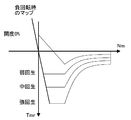
- the regenerative torque limit map includes a stop limit map 71, a sudden braking limit map 72, a creep limit map 73, as shown in FIG.
- a limit map 74 at the time of brake operation and a limit map 75 at the time of slip control are provided.
- the inclination of the limit characteristic is determined based on the result of the vehicle experiment or the like so that the acceleration vibration can be suppressed without impairing the feeling of deceleration to the low speed range.
- the limit map 72 for other sudden braking, the limit map 74 for brake operation, and the limit map 75 for slip control also have limit characteristics for stopping the vehicle, similar to the limit map 71 for stopping.
- the stop limit map 71 has a limit characteristic in the second quadrant which is negative rotation and drive torque. Note that the limit map 72 for other sudden braking, the limit map 73 for creep, the limit map 74 for brake operation, and the limit map 75 for slip control are also applied to the second quadrant in the same manner as the limit map 71 for stopping. Has limit characteristics.
- the sudden braking limit map 72 is selected when a further deceleration instruction (steering SW_DOWN) is issued immediately before stopping, and the slope of the limit characteristic is steeper than that of the stopping limit map 71.
- the inclination of the limit characteristic is such that the stopping distance becomes the shortest when the vehicle stops suddenly, and is determined based on the result of the vehicle experiment or the like.
- the creep limit map 73 is switched from the limit map selected at that time when an acceleration instruction (steering SW_UP) is issued just before stopping.
- a creep characteristic is set so that the limit map lower limit value Tlim is positive at a vehicle speed of 0 km / h so as to be suitable for low speed travel (creep travel) just before stopping.
- the inclination of the creep characteristic is determined based on the result of a vehicle experiment or the like, which is suitable for traveling following the front vehicle.
- the limit map 74 at the time of the brake operation is selected when the driver operates the mechanical brake just before stopping, and the slope of the limit characteristic is more gradual than the limit map 71 of stopping.
- the limit map 74 at the time of the brake operation has an inclination of limit characteristics corresponding to the brake stroke amount. That is, it is determined that the greater the brake stroke amount, the greater the dependency of the brake, and the slope of the limit characteristic is moderated. The smaller the stroke amount, the less the dependency of the brake is determined, and the limit of the limit map 71 for stopping is determined.
- the slope is close to the characteristics, and is determined based on the results of vehicle experiments.
- the brake operation amount may be brake fluid pressure or the like.
- the limit map 75 at the time of slip control is selected when slip control (ABS control) for suppressing drive wheel slip is performed just before stopping, and the slope of the limit characteristic is made gentler than the limit map 71 of stopping.
- the limit map 75 at the time of slip control is such that the slope of the limit characteristic becomes gentler as the command torque value Tm at the time of slip control is larger. That is, the larger the command torque Tm, the higher the road surface ⁇ is, and the slope is closer to the stop limit map 71. The smaller the command torque Tm is, the lower the road surface ⁇ is, and the slope of the limit characteristic is determined. Decrease based on the results of vehicle experiments.
- a first map selection unit 76 As the map selection unit, as shown in FIG. 7, a first map selection unit 76, a second map selection unit 77, a third map selection unit 78, And a fourth map selection unit 79. Then, a torque value obtained based on any selected map and the motor rotation speed Nm is set as a limit map lower limit value Tlim.
- the first map selection unit 76 switches the selection to the limit map 72 for sudden braking when a stop deceleration map (steering SW_DOWN) is issued when the stop limit map 71 is selected just before stopping.
- the second map selection unit 77 displays the creep limit map 73 when an acceleration instruction (steering SW_UP) is issued. Switch the selection.
- the third map selection unit 78 switches the selection to the limit map 74 during braking operation. .
- the fourth map selection unit 79 selects the slip determination flag when the stop limit map 71, the sudden braking limit map 72, the creep limit map 73, or the brake operation limit map 74 is selected just before stopping. When is established, the selection is switched to the limit map 75 at the time of slip control.
- the limit torque calculation configuration includes a gradient correction torque calculation unit 80, a torque adder 81, and a torque limiter 82 as shown in FIG. Yes.
- the gradient correction torque calculation unit 80 is provided for performing regeneration command torque limiting processing with gradient correspondence to changes in road surface gradient, and gradient correction torque according to the estimated gradient value ⁇ of the road surface gradient. Calculate Tg. A detailed calculation method of the gradient correction torque Tg will be described later.
- the torque adder 81 adds the limit map lower limit value Tlim and the gradient correction torque Tg and sets the added value as the regenerative torque lower limit value Tmin.
- the torque limiter 82 sets a value obtained by limiting the command torque Tm with the regenerative torque lower limit value Tmin as a limit torque Tm_fin.
- FIG. 9 is a flowchart illustrating a regeneration command torque calculation process in the regeneration brake control process according to the first embodiment. Hereinafter, each step of FIG. 9 showing the regenerative command torque calculation processing configuration will be described.
- deceleration instruction information for selecting a limit map instead of the regeneration amount change instruction (operation to the steering switch 11) from the driver as regenerative amount change information, Alternatively, it is used as acceleration instruction information.
- step S5-1 it is determined whether or not the regeneration command is valid based on the regenerative amount and accelerator opening degree ⁇ according to the driver's intention calculated in step S2. If YES (regenerative command is valid), the process proceeds to step S5-2. If NO (regenerative command is invalid), the process proceeds to step S5-18.
- Step S5-2 following the determination that the regeneration command is valid in Step S5-1, it is determined whether or not the stop regeneration switch 15 that can be operated with the driver's intention is ON. If YES (stop regeneration SW_ON) and regeneration until stopping, the process proceeds to step S5-6. If NO (stop regeneration SW_OFF) and regeneration to creep occurs, the process proceeds to step S5-3.
- step S5-3 following the determination that the stop regeneration SW_OFF is in step S5-2, the limit map 73 at creep is selected, and the limit map lower limit value is determined by the motor rotation speed Nm and the limit map 73 at creep. Tlim is calculated and stored, and the process proceeds to step S5-4.
- step S5-4 following the calculation of the limit map lower limit value Tlim in step S5-3, the motor rotation speed Nm is in the low speed range, and the down operation (deceleration instruction operation) increases the regeneration amount with respect to the steering switch 11. ) Is determined. If YES (with down operation), the process proceeds to step S5-5. If NO (no down operation), the process proceeds to step S5-9.
- step S5-5 following the determination that there is a down operation in step S5-4, the creep limit map 73 is switched to the stop limit map 71, and the motor speed Nm and the stop limit map 71 The map lower limit value Tlim is calculated and stored, and the process proceeds to step S5-9.
- step S5-6 following the determination that the stop regeneration SW_ON is in step S5-2, the stop limit map 71 is selected, and the limit map lower limit value Tlim is calculated based on the motor rotation speed Nm and the stop limit map 71. Calculate and store, and proceed to Step S5-7.
- step S5-7 following the calculation of the limit map lower limit value Tlim in step S5-6, the motor rotation speed Nm is in the low speed range and the steering switch 11 is operated to increase the regeneration amount (acceleration instruction operation). ) Is determined. If YES (with up operation), the process proceeds to step S5-8. If NO (without up operation), the process proceeds to step S5-9.
- step S5-8 following the determination that there is an up operation in step S5-7, the vehicle is switched from the stop limit map 71 to the limit map 73 at the time of creep, and based on the motor rotation speed Nm and the limit map 73 at the time of creep, The limit map lower limit value Tlim is calculated and stored, and the process proceeds to step S5-9.
- step S5-9 following the calculation of the limit map lower limit value Tlim in step S5-5 or step S5-8, whether or not a down operation (acceleration instruction operation) for increasing the regeneration amount has been performed on the steering switch 11 Is judged. If YES (with down operation), the process proceeds to step S5-10. If NO (no down operation), the process proceeds to step S5-11.
- a down operation acceleration instruction operation
- step S5-10 following the determination that there is a down operation in step S5-9, the sudden braking limit map 72 is selected, and the limit map lower limit value Tlim is determined from the motor rotation speed Nm and the sudden braking limit map 72. Calculate and store, and proceed to Step S5-10.
- step S5-11 following the determination that there is no down operation in step S5-9 or the calculation of the limit map lower limit value Tlim in step S5-10, whether the brake is depressed by the brake stroke sensor 14 Judge whether or not. If YES (with brake operation), proceed to step S5-12. If NO (no brake operation), proceed to step S5-13.
- step S5-12 following the determination that there is a brake operation in step S5-11, the limit map 74 at the time of brake operation is selected, and from the motor rotation speed Nm, the brake stroke amount, and the limit map 74 at the time of brake operation, The limit map lower limit value Tlim is calculated and stored, and the process proceeds to step S5-13.
- the limit map lower limit value Tlim is calculated and stored, and the process proceeds to step S5-15.
- step S5-16 following the calculation of the gradient correction torque Tg in step S5-15, the limit map lower limit value Tlim and the gradient correction torque Tg in step S5-15 are added to calculate the regenerative torque lower limit value Tmin. Proceed to step S5-17.
- step S5-17 following the calculation of regenerative torque lower limit value Tmin in step S5-16, limit processing is performed on command torque Tm with regenerative torque lower limit value Tmin, limit torque Tm_fin is calculated, and step S5-18 is performed. move on.
- This limit processing is a limit according to the slope determined in steps S5-2 to S5-16 even if there is an instruction to change the regeneration amount in an electric vehicle system that can change the regeneration amount according to the driver's intention.
- Command torque Tm limit processing is performed using the map lower limit value Tlim.
- step S5-18 following the determination that the regenerative command is invalid in step S5-1 or the calculation of the limit torque Tm_fin in step S5-17, the command torque Tm Alternatively, the limit torque Tm_fin is selected, the selected torque is stored as the drive regeneration command torque Tm *, and the process proceeds to the end.
- the effects of the regenerative braking control device for the electric vehicle according to the first embodiment are “regenerative amount changing action before entering limit processing”, “regenerative braking stop basic action by limit processing”, and “regenerative braking stopping action in different stopping modes”. This will be explained separately.
- the regeneration command torque Tmr is obtained using the map.
- one characteristic corresponding to the regeneration amount is selected from the four regeneration amount characteristics of the regeneration torque map shown in FIG. 4, and the regeneration command torque Tmr is obtained from the selected one characteristic and the motor rotational speed Nm.
- step S6 the regeneration command torque Tmr obtained in step S2 is directly used as the drive regeneration command torque Tm *, and the dq-axis current target values id * and iq * are tabled from the motor rotation speed Nm and the DC voltage value Vdc. It is obtained by referring more.
- step S7 the current command value calculation process in step S6 is performed, and finally the PWM signal (on duty) tu [%], tv [from the three-phase voltage command values vu, vv, vw and the DC voltage Vdc. %] And tw [%] are calculated.
- the opening / closing control of the switching element of the inverter 3 by the PWM signal obtained in this way makes it possible to drive the electric motor 4 with a desired torque indicated by the drive regeneration command torque Tm *.
- the characteristic corresponding to the regenerative amount is selected from the regenerative torque map shown in FIG. 4, and the selected characteristic and the motor rotation are selected.
- the amount of regeneration can be obtained using several Nm (vehicle speed).
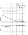
- FIG. 10 is a time chart showing a response of deceleration when the braking force is applied to the motor with the regeneration amount intended by the driver from the running state and the vehicle is decelerated to the stop in the comparative example.
- the regenerative amount (command torque) is reduced until time t2 when the wheel speed becomes zero without decreasing the regenerative amount (command torque) toward zero even at time t1 when reaching the vehicle speed just before stopping. Kept constant. Then, at time t2 when the wheel speed becomes zero, the regeneration amount (command torque) is returned by the step characteristic.
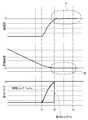
- FIG. 11 shows the result in the case of the first embodiment in which limit processing is executed to limit the regenerative amount to a small value as the vehicle speed decreases when the vehicle is about to stop.
- the driver's regenerative command represents the deceleration state, and the command torque is returned to the step characteristic at time t2 when the wheel speed becomes zero.
- the command torque Tm is gradually limited by the limit torque Tm_fin corresponding to the motor rotation speed Nm (vehicle speed) from time t1 just before stopping to time t2.
- the limit torque Tm_fin corresponding to the motor rotation speed Nm (vehicle speed) from time t1 just before stopping to time t2.
- the limit torque Tm_fin the deceleration is gradually removed from time t1 to time t2, and from time t2 to time t3 as shown in the deceleration characteristics in the frame A of FIG. It can be seen that no acceleration vibration occurs.
- the amount of regeneration just before stopping is limited according to the motor rotation speed Nm (vehicle speed), so that the passenger does not feel shock or unpleasant vibration, and smooth deceleration without acceleration vibration is achieved. Can be realized just before stopping.
- Nm vehicle speed
- the vehicle can be decelerated without using the braking force of the mechanical braking means until just before stopping, it can be regenerated reliably until just before stopping, and an improvement in power consumption can be expected.
- the regenerative command torque limiting process is performed without accepting the instruction.
- the regenerative amount change instruction is not accepted from the driver, so that the regenerative amount is suddenly changed by the driver just before stopping, so that the front-rear G fluctuation increases or the uphill road slips down. Is prevented.
- FIG. 12 is a regenerative torque map showing the regenerative command torque limiting action when the vehicle stops on a flat road.
- action at the time of a flat road stop is demonstrated.
- the regenerative torque limit map a configuration having limit maps 71, 72, 74, and 75 that are set to limit characteristics that limit the regenerative amount as the vehicle speed decreases so as to stop the vehicle is employed (FIG. 1). 7). With this configuration, as shown in FIG.
- FIG. 13 is a regenerative torque map showing the regenerative command torque limiting action when stopping on an uphill road.
- action at the time of an uphill stop is demonstrated.
- the limit maps 71, 72, 74, and 75 employ a configuration in which the second quadrant, which is a negative rotation and a driving torque, also has limit characteristics (FIG. 7). For example, when regenerating during climbing, if there is no limit characteristic in the second quadrant, the vehicle may drop suddenly after stopping. On the other hand, as shown in FIG.
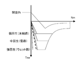
- FIG. 14 is a regenerative torque map showing the regenerative command torque limiting action when the road surface gradients are different.
- action at the time of a gradient road surface stop is demonstrated.
- the regeneration command torque limit a configuration is adopted in which the regeneration command torque limit process is performed with the gradient correspondence to the change in the road surface gradient (step S5-15 ⁇ step S5-16 in FIG. 9). With this configuration, as shown in FIG.
- the regeneration command torque limit it has a gradient correction torque calculation unit 80 for calculating the gradient correction torque Tg according to the road surface gradient, and the flat road reference limit map lower limit value Tlim obtained by the regeneration command torque limit process is A configuration was adopted in which the regenerative torque lower limit value Tmin is calculated by correcting with the gradient correction torque Tg (FIG. 7).
- the configuration taking the gradient correction torque Tg according to the road surface gradient into account it is not necessary to prepare a large number of limit maps according to the road surface gradient as the limit map, and it is only necessary to prepare a limit map based on a flat road. Therefore, it is possible to smoothly stop the vehicle on any slope road surface such as an ascending slope or a descending slope while having a simple configuration without preparing a large number of limit maps according to the road surface slope.
- FIG. 15 is a regenerative torque map diagram showing a regenerative command torque limiting action when a brake operation by the driver intervenes.
- the limiting action at the time of brake operation intervention will be described.
- the regenerative command torque limit as a regenerative torque limit map, there is a limit map 74 at the time of brake operation with a gentler slope than the limit characteristic at the time of stopping on a flat road (FIG. 7). Then, a configuration is adopted in which the limit map 74 at the time of brake operation is selected when the driver operates the mechanical brake immediately before stopping (step S5-11 ⁇ step S5-12 in FIG. 9).
- the limit map 74 at the time of the brake operation adopts a configuration in which the slope of the limit characteristic becomes gentler as the driver's operation amount with respect to the mechanical brake is larger (FIG. 7). Therefore, by determining the inclination of the limit map 74 at the time of the brake operation according to the brake operation amount by the driver, the uncomfortable feeling of the deceleration G with respect to the brake operation amount can be reduced.
- FIG. 16 is a regenerative torque map diagram showing a regenerative command torque limiting action when slip control (paddle regenerative ABS control) intervenes on a low ⁇ road.
- action at the time of slip control intervention is demonstrated.
- the regenerative torque limit map has a limit map 75 at the time of slip control with a gentler slope than the limit characteristic at the time of stopping on a flat road (FIG. 7).
- step S5-13-> step S5-14 of FIG. 9 the structure which selects the limit map 75 at the time of slip control was employ
- the structure which selects the limit map 75 at the time of slip control was employ
- the slope of the limit characteristic is moderated, so that the vehicle can be stopped smoothly even when the vehicle is stopped on a low ⁇ road where slip control intervenes.
- FIG. 17 is a regenerative torque map showing the regenerative command torque limiting action when the deceleration instruction (paddle DOWN) re-intervenes.
- the limiting action at the time of deceleration instruction intervention will be described.
- the regenerative command torque limit as a regenerative torque limit map, there is a sudden braking limit map 72 having a steeper slope than the limit characteristic when the vehicle stops on a flat road (FIG. 7).
- step S5-9-> step S5 of FIG. 9 the structure which selects the limit map 72 of sudden braking when the further deceleration instruction
- FIG. 18 is a regenerative torque map diagram showing a regenerative command torque limiting action when an acceleration instruction (paddle UP) intervenes.
- an acceleration instruction praddle UP
- FIG. 18 the limiting action at the time of intervention of acceleration instructions will be described.
- the regenerative command torque limit as a regenerative torque limit map, there are a stop limit map 71 suitable for stopping and a creep limit map 73 in which a creep characteristic suitable for low speed running is set (FIG. 7). .
- a configuration is adopted in which a limit map 73 at the time of creep is selected when an acceleration instruction is issued just before stopping (step S5-7 ⁇ step S5-8 in FIG. 9). ).
- a limit map 73 at the time of creep is selected when an acceleration instruction is issued just before stopping.
- the vehicle is switched from the vehicle stop limit map 71 to the creep limit map 73 as shown in FIG. As a result, the vehicle moves forward slowly without stopping. Therefore, when an acceleration instruction is issued just before the vehicle stops, it is possible to improve the sensation of the acceleration request just before the vehicle is stopped by continuing the vehicle slowly without performing the accelerator stepping operation in which the driving torque suddenly occurs. .
- FIG. 19 is a regenerative torque map diagram showing a regenerative command torque limiting action when a deceleration instruction (paddle DOWN) intervenes.
- a deceleration instruction (paddle DOWN) intervenes.
- the limiting action at the time of deceleration instruction intervention will be described.
- the creep limit map 73 when the creep limit map 73 is selected, a configuration is adopted in which switching is made to the stop limit map 71 when a deceleration instruction is issued just before stopping (step S5 in FIG. 9). -4 ⁇ step S5-5).
- the creep limit map 73 is switched to the stopping limit map 71 as shown in FIG.
- the stopping limit map 71 For example, in a scene that follows the preceding vehicle, such as traffic jams or waiting for traffic lights, it is possible to select a creep limit map 73 and continue running at a low speed. Therefore, when the creep limit map 73 is selected, the vehicle can be stopped at the position intended by the driver by switching to the stop limit map 71 only when the deceleration instruction is operated.
- an electric motor 4 coupled to the drive wheel, an electric motor controller 1 for controlling power running / regeneration of the electric motor 4, a regeneration amount setting means (steering switch 11) for setting a regeneration amount by a driver operation
- the electric motor controller 1 has regenerative command torque limiting means (step S5, FIG. 7, FIG. 9 in FIG. 2) that limits the regenerative amount to a small value as the vehicle speed decreases when the vehicle is about to stop. For this reason, in the electric vehicle which can change the amount of regeneration according to the driver's intention, it is possible to ensure a smooth deceleration feeling without acceleration vibration until just before stopping.
- step S5 When the torque limiting process is started, the regeneration command torque limiting means (step S5, FIG. 7, FIG. 9 in FIG. 2) does not accept a regeneration amount change instruction from the driver, Performs regenerative command torque limit processing. For this reason, in addition to the effect of (1), it is possible to prevent the forward / backward G fluctuation from increasing or the sliding down on the uphill road by suddenly changing the regeneration amount immediately before stopping by the driver. .
- the regenerative command torque limiting means (steps S5, FIG. 7, and FIG. 9 in FIG. 2) has a limit characteristic that limits the regenerative amount as the vehicle speed decreases so that the vehicle stops as a regenerative torque limit map. It has set limit maps 71, 72, 74, 75 (FIG. 7). For this reason, in addition to the effect of (1) or (2), acceleration vibration (front-rear G vibration) caused by pitching or the like that occurs when the vehicle is stopped can be suppressed, and the vehicle can be stopped smoothly without a sense of incongruity. it can.
- the limit maps 71, 72, 74, and 75 give the second quadrant, which is a negative rotation and drive torque, to have limit characteristics (FIG. 7). For this reason, in addition to the effect of (3), after the vehicle stops on the uphill road, the driver can be urged to perform the brake operation by the gentle sliding of the vehicle.
- the regenerative command torque limiting means (steps S5, 7, and 9 in FIG. 2) performs a regenerative command torque limiting process with a gradient correspondence to changes in the road surface gradient (step S5 in FIG. 9). -15 ⁇ Step S5-16). For this reason, in addition to the effects (1) to (4), the vehicle is prevented from sliding backward when the vehicle is climbing up, and the vehicle is prevented from sliding forward when the vehicle is parked down. Thus, it is possible to stop smoothly regardless of stopping on a slope road.
- the regeneration command torque limiting means (step S5, FIG. 7, FIG. 9 in FIG. 2) includes a gradient correction torque calculation unit 80 that calculates a gradient correction torque Tg according to the road surface gradient, and the regeneration command torque.
- the regenerative torque lower limit value Tmin is calculated by correcting the flat road reference limit map lower limit value Tlim obtained by the restriction process with the gradient correction torque Tg (FIG. 7). For this reason, in addition to the effect of (5), it is possible to make a smooth stop on any slope road surface due to an ascending or descending slope while having a simple configuration without preparing a large number of limit maps according to the road slope. .
- the regenerative command torque limiting means (steps S5, FIG. 7, and FIG. 9 in FIG. 2) is a regenerative torque limit map, which is a limit map at the time of brake operation with a gentler slope than the limit characteristics at the time of stopping on a flat road.
- 74 (FIG. 7)
- the limit map 74 at the time of the brake operation is selected (step S5-11 ⁇ step S5-12 in FIG. 9).
- the driver feels uncomfortable when the brake is released by changing to a gentle slope limit characteristic. Can be suppressed.
- the regenerative command torque limiting means (step S5 in FIG. 2, FIG. 7 and FIG. 9) is a limit map for slip control with a gentler slope than the limit characteristic for stopping on a flat road as a regenerative torque limit map. 75 (FIG. 7), and when slip control is performed to suppress drive wheel slip just before stopping, the limit map 75 for the slip control is selected (step S5-13 ⁇ step S5-14 in FIG. 9). .
- the slope of the limit characteristic is made gentle so that the low ⁇ road on which slip control intervenes. Even when the vehicle is stopped, the vehicle can be stopped smoothly.
- the regenerative command torque limiting means uses the regenerative torque limit map 72 as a regenerative torque limit map for sudden braking with a steeper slope than the limit characteristics when the vehicle is stopped on a flat road.
- FIG. 7 when the limit map 75 at the time of the slip control is selected, if a further deceleration instruction is issued just before stopping, the limit map 72 for the sudden braking is selected (step S5- in FIG. 9). 9 ⁇ Step S5-10).
- the limit map 75 at the time of slip control is selected, if there is a further deceleration instruction just before stopping, the slope of the limit characteristic becomes steep, thereby shortening the stop distance. can do.
- the regenerative command torque limiting means (steps S5, FIG. 7, and FIG. 9 in FIG. 2) includes a stop limit map 71 suitable for stopping and a creep characteristic suitable for low-speed driving as a regenerative torque limit map.
- the stop limit map 71 is selected and the stop limit map 71 is selected, when the acceleration instruction is issued just before the stop, the creep limit map 73 is selected (FIG. 9).
- Step S5-7 ⁇ Step S5-8).
- step S5 in FIG. 2, FIGS. 7 and 9 The regenerative command torque limiting means (step S5 in FIG. 2, FIGS. 7 and 9), when the creep limit map 73 is selected, when a deceleration instruction is issued just before stopping, Switching to the limit map 71 (step S5-4 ⁇ step S5-5 in FIG. 9). For this reason, in addition to the effect of (11), when the creep limit map 73 is selected, the vehicle is stopped at the target position by switching to the stop limit map 71 only when the deceleration instruction is operated. Can be able to.
- the regenerative brake control device for an electric vehicle has been described based on the first embodiment.
- the specific configuration is not limited to the first embodiment, and the claims relate to each claim. Design changes and additions are allowed without departing from the scope of the invention.
- a regenerative command torque limiting means various limit maps 71, 72, 73, 74, 75 are used just before stopping, and the regenerative amount is limited to a small value as the motor rotational speed (vehicle speed) decreases.
- the regeneration command torque limiting means may be an example in which the limit torque is obtained by calculation and the regeneration amount is limited to be small when the vehicle speed range is just before stopping without using the limit map.
- Example 1 shows an example in which the regenerative brake control device of the present invention is applied to an electric vehicle.
- the regenerative brake control device for an electric vehicle of the present invention can also be applied to a hybrid vehicle equipped with an electric motor.
Landscapes
- Engineering & Computer Science (AREA)
- Transportation (AREA)
- Mechanical Engineering (AREA)
- Power Engineering (AREA)
- Chemical & Material Sciences (AREA)
- Combustion & Propulsion (AREA)
- Physics & Mathematics (AREA)
- Electromagnetism (AREA)
- Electric Propulsion And Braking For Vehicles (AREA)
- Regulating Braking Force (AREA)
Abstract
La présente invention vise à garantir un ralentissement doux et sans embardée jusqu'à l'arrêt d'un véhicule électrique capable de faire varier un taux de récupération en fonction de la volonté du conducteur. L'invention est équipée d'un moteur électrique (4) relié à une roue d'entraînement, d'un dispositif de commande de moteur électrique (1) pour commander l'entraînement et la récupération d'un moteur électrique (4), et d'un commutateur de direction (11) pour régler un taux de récupération conformément aux opérations du conducteur. Dans ce système de véhicule électrique dans lequel un taux de récupération est modifiable en fonction de la volonté du conducteur, le dispositif de commande de moteur électrique (1) comprend un moyen de limitation de couple commande de récupération (étape S5 des figures 2, 7 et 9) pour limiter un taux de récupération pour que ce dernier diminue à mesure que la vitesse du véhicule baisse lorsqu'un véhicule veut s'arrêter.
Priority Applications (3)
| Application Number | Priority Date | Filing Date | Title |
|---|---|---|---|
| US14/375,165 US10300795B2 (en) | 2012-01-31 | 2013-01-24 | Regenerative braking control device of electric vehicle |
| EP13743441.1A EP2810811B1 (fr) | 2012-01-31 | 2013-01-24 | Dispositif de commande de freinage par récupération pour véhicule électrique |
| CN201380006044.9A CN104066613B (zh) | 2012-01-31 | 2013-01-24 | 电动车辆的再生制动器控制装置 |
Applications Claiming Priority (2)
| Application Number | Priority Date | Filing Date | Title |
|---|---|---|---|
| JP2012-018057 | 2012-01-31 | ||
| JP2012018057A JP5915208B2 (ja) | 2012-01-31 | 2012-01-31 | 電動車両の回生ブレーキ制御装置 |
Publications (1)
| Publication Number | Publication Date |
|---|---|
| WO2013115042A1 true WO2013115042A1 (fr) | 2013-08-08 |
Family
ID=48905084
Family Applications (1)
| Application Number | Title | Priority Date | Filing Date |
|---|---|---|---|
| PCT/JP2013/051373 WO2013115042A1 (fr) | 2012-01-31 | 2013-01-24 | Dispositif de commande de freinage par récupération pour véhicule électrique |
Country Status (5)
| Country | Link |
|---|---|
| US (1) | US10300795B2 (fr) |
| EP (1) | EP2810811B1 (fr) |
| JP (1) | JP5915208B2 (fr) |
| CN (1) | CN104066613B (fr) |
| WO (1) | WO2013115042A1 (fr) |
Cited By (7)
| Publication number | Priority date | Publication date | Assignee | Title |
|---|---|---|---|---|
| WO2015079574A1 (fr) * | 2013-11-29 | 2015-06-04 | 日産自動車株式会社 | Dispositif de commande pour véhicule électrique et procédé de commande pour véhicule électrique |
| WO2015083213A1 (fr) * | 2013-12-02 | 2015-06-11 | 日産自動車株式会社 | Dispositif et procédé de commande de véhicule électrique |
| CN105899397A (zh) * | 2014-01-10 | 2016-08-24 | 日产自动车株式会社 | 电动车辆的控制装置以及电动车辆的控制方法 |
| JP2018007441A (ja) * | 2016-07-04 | 2018-01-11 | トヨタ自動車株式会社 | 自動車 |
| RU2670563C1 (ru) * | 2015-01-26 | 2018-10-23 | Ниссан Мотор Ко., Лтд. | Устройство управления для электромоторного транспортного средства и способ управления для электромоторного транспортного средства |
| JP2019126148A (ja) * | 2018-01-15 | 2019-07-25 | 日立オートモティブシステムズ株式会社 | 電動車両の制御装置、電動車両の制御システム及び電動車両の制御方法 |
| KR20200050028A (ko) * | 2018-10-31 | 2020-05-11 | 현대자동차주식회사 | 친환경자동차의 제동 제어 장치 |
Families Citing this family (30)
| Publication number | Priority date | Publication date | Assignee | Title |
|---|---|---|---|---|
| JP6167363B2 (ja) * | 2013-09-12 | 2017-07-26 | 日立オートモティブシステムズ株式会社 | 電動車両の制御装置及び電動車両の制御方法 |
| JP6237789B2 (ja) * | 2013-11-29 | 2017-11-29 | 日産自動車株式会社 | 電動車両の制御装置および電動車両の制御方法 |
| CN105764742B (zh) * | 2013-12-02 | 2018-04-27 | 日产自动车株式会社 | 电动车辆的控制装置以及电动车辆的控制方法 |
| JP6492399B2 (ja) * | 2014-01-10 | 2019-04-03 | 日産自動車株式会社 | 電動車両の制御装置および電動車両の制御方法 |
| JP5943011B2 (ja) * | 2014-01-31 | 2016-06-29 | トヨタ自動車株式会社 | ハイブリッド車両 |
| ES2826373T3 (es) | 2014-02-28 | 2021-05-18 | Bae Sys Controls Inc | Limitador de tensión de cuatro cuadrantes para un control de máquina de flujo de rotor orientado |
| JP6183335B2 (ja) * | 2014-11-12 | 2017-08-23 | トヨタ自動車株式会社 | 車両 |
| KR20160090524A (ko) * | 2015-01-22 | 2016-08-01 | 엘지전자 주식회사 | 전기 자동차 및 전기 자동차의 제어 방법 |
| KR101795130B1 (ko) * | 2015-04-16 | 2017-12-01 | 현대자동차주식회사 | 전기 자동차의 크립주행 제어 장치 및 그 방법 |
| KR101703601B1 (ko) * | 2015-07-13 | 2017-02-22 | 현대자동차 주식회사 | 차량의 제어방법 |
| US10953756B2 (en) * | 2015-07-15 | 2021-03-23 | Ford Global Technologies, Llc | Adaptive regenerative braking method and system |
| JP6501069B2 (ja) * | 2015-07-24 | 2019-04-17 | 三菱自動車工業株式会社 | 車両の回生制御装置 |
| JP6649600B2 (ja) * | 2015-08-03 | 2020-02-19 | 三菱自動車工業株式会社 | 電動車両の回生制御装置 |
| CN108025710B (zh) * | 2015-09-16 | 2020-08-04 | 三菱自动车工业株式会社 | 再生制动控制装置 |
| JP6586856B2 (ja) * | 2015-10-22 | 2019-10-09 | 日産自動車株式会社 | 電動車両の制御方法、及び、制御装置 |
| JP6686384B2 (ja) * | 2015-11-20 | 2020-04-22 | いすゞ自動車株式会社 | ハイブリッド車両の回生電力量制御システム、ハイブリッド車両及びハイブリッド車両の回生電力量制御方法 |
| US11091180B2 (en) | 2016-02-02 | 2021-08-17 | Mitsubishi Electric Corporation | Brake control device for electric vehicle |
| JP2017143685A (ja) * | 2016-02-12 | 2017-08-17 | 三菱自動車工業株式会社 | 回生制御装置 |
| US10454392B2 (en) | 2016-11-11 | 2019-10-22 | Hubbell Incorporated | Motor drive and method of emergency stop braking |
| JP2018157641A (ja) * | 2017-03-16 | 2018-10-04 | 三菱自動車工業株式会社 | ブレーキ回生量制御装置 |
| DE102018216559A1 (de) * | 2018-09-27 | 2020-04-02 | Bayerische Motoren Werke Aktiengesellschaft | Verfahren und Vorrichtung zum Ansteuern eines Elektromotors für ein Hybrid- oder Elektrofahrzeug |
| AT522508B1 (de) * | 2019-05-13 | 2022-02-15 | Avl List Gmbh | Verfahren zur Regelung des Antriebs eines elektrischen Fahrzeugs |
| JP7280776B2 (ja) * | 2019-08-08 | 2023-05-24 | 日立Astemo株式会社 | 電動車両の制御装置、制御方法および制御システム |
| DE102019213773A1 (de) * | 2019-09-10 | 2021-03-11 | Robert Bosch Gmbh | Verfahren zum Steuern einer Bremswirkung an einem Fahrzeug mit einem elektrischen Antriebssystem und System für eine Bremsunterstützung bei einem Fahrzeug mit einem elektrischen Antriebssystem |
| KR20210073632A (ko) * | 2019-12-10 | 2021-06-21 | 현대자동차주식회사 | 전기 모터를 구비하는 차량 및 그를 위한 제동등 제어 방법 |
| JP7403920B2 (ja) | 2020-02-28 | 2023-12-25 | ダイハツ工業株式会社 | 電動車両の制御装置 |
| JP7480696B2 (ja) | 2020-12-23 | 2024-05-10 | 株式会社デンソー | 制御装置 |
| JP7420088B2 (ja) | 2021-01-22 | 2024-01-23 | 株式会社デンソー | 制御装置、プログラム |
| JP2023111443A (ja) * | 2022-01-31 | 2023-08-10 | 株式会社デンソー | 移動体の制御システム、プログラム |
| WO2023247010A1 (fr) * | 2022-06-20 | 2023-12-28 | Volvo Truck Corporation | Commande de force devant être appliquée par paire de roues sur une remorque |
Citations (6)
| Publication number | Priority date | Publication date | Assignee | Title |
|---|---|---|---|---|
| JPH0670406A (ja) * | 1992-08-08 | 1994-03-11 | Nissan Motor Co Ltd | 電気自動車の走行制御装置 |
| JPH0879907A (ja) | 1994-09-01 | 1996-03-22 | Mitsubishi Motors Corp | 電気自動車用回生ブレーキ制御装置 |
| JP2002058105A (ja) * | 2000-08-10 | 2002-02-22 | Fuji Heavy Ind Ltd | 電気自動車の回生ブレーキ制御装置 |
| JP2004215447A (ja) * | 2003-01-07 | 2004-07-29 | Toyota Industries Corp | 車両の走行制御装置 |
| JP2007151397A (ja) * | 2007-02-27 | 2007-06-14 | Toyota Motor Corp | 車両用回生制動装置 |
| JP2011147208A (ja) * | 2010-01-12 | 2011-07-28 | Toyota Motor Corp | 電動車両 |
Family Cites Families (10)
| Publication number | Priority date | Publication date | Assignee | Title |
|---|---|---|---|---|
| EP0770511B1 (fr) * | 1994-11-29 | 2000-03-15 | Mitsubishi Jidosha Kogyo Kabushiki Kaisha | Commande de frein pour vehicule electrique |
| JPH0937407A (ja) * | 1995-07-18 | 1997-02-07 | Toyota Motor Corp | 回生制動制御装置 |
| JP2000069603A (ja) * | 1998-08-24 | 2000-03-03 | Mitsubishi Heavy Ind Ltd | バッテリ車両の回生制動装置 |
| JP2007030631A (ja) * | 2005-07-25 | 2007-02-08 | Advics:Kk | 車両用ブレーキ制御装置 |
| JP4743121B2 (ja) * | 2006-03-29 | 2011-08-10 | 日産自動車株式会社 | 車両の衝突時ブレーキ配分制御装置 |
| CN101811443B (zh) * | 2008-08-06 | 2012-04-25 | 山东理工大学 | 汽车制动能量再生控制系统 |
| JP5663969B2 (ja) * | 2009-06-30 | 2015-02-04 | 株式会社アドヴィックス | 前後加速度制御装置 |
| US8612074B2 (en) * | 2010-05-07 | 2013-12-17 | GM Global Technology Operations LLC | Regenerative braking control in vehicles |
| US20120133202A1 (en) * | 2010-11-29 | 2012-05-31 | Gm Global Technology Operations, Inc. | Dynamic regenerative braking torque control |
| US20130162009A1 (en) * | 2011-12-22 | 2013-06-27 | Coda Automotive, Inc. | Electric vehicle regenerative braking system |
-
2012
- 2012-01-31 JP JP2012018057A patent/JP5915208B2/ja active Active
-
2013
- 2013-01-24 EP EP13743441.1A patent/EP2810811B1/fr active Active
- 2013-01-24 US US14/375,165 patent/US10300795B2/en active Active
- 2013-01-24 WO PCT/JP2013/051373 patent/WO2013115042A1/fr active Application Filing
- 2013-01-24 CN CN201380006044.9A patent/CN104066613B/zh active Active
Patent Citations (6)
| Publication number | Priority date | Publication date | Assignee | Title |
|---|---|---|---|---|
| JPH0670406A (ja) * | 1992-08-08 | 1994-03-11 | Nissan Motor Co Ltd | 電気自動車の走行制御装置 |
| JPH0879907A (ja) | 1994-09-01 | 1996-03-22 | Mitsubishi Motors Corp | 電気自動車用回生ブレーキ制御装置 |
| JP2002058105A (ja) * | 2000-08-10 | 2002-02-22 | Fuji Heavy Ind Ltd | 電気自動車の回生ブレーキ制御装置 |
| JP2004215447A (ja) * | 2003-01-07 | 2004-07-29 | Toyota Industries Corp | 車両の走行制御装置 |
| JP2007151397A (ja) * | 2007-02-27 | 2007-06-14 | Toyota Motor Corp | 車両用回生制動装置 |
| JP2011147208A (ja) * | 2010-01-12 | 2011-07-28 | Toyota Motor Corp | 電動車両 |
Non-Patent Citations (1)
| Title |
|---|
| See also references of EP2810811A4 * |
Cited By (19)
| Publication number | Priority date | Publication date | Assignee | Title |
|---|---|---|---|---|
| WO2015079574A1 (fr) * | 2013-11-29 | 2015-06-04 | 日産自動車株式会社 | Dispositif de commande pour véhicule électrique et procédé de commande pour véhicule électrique |
| CN105764739B (zh) * | 2013-12-02 | 2018-06-29 | 日产自动车株式会社 | 电动车辆的控制装置以及电动车辆的控制方法 |
| CN105764739A (zh) * | 2013-12-02 | 2016-07-13 | 日产自动车株式会社 | 电动车辆的控制装置以及电动车辆的控制方法 |
| US9902272B2 (en) | 2013-12-02 | 2018-02-27 | Nissan Motor Co., Ltd. | Control device for electric motor vehicle and control method for electric motor vehicle |
| WO2015083213A1 (fr) * | 2013-12-02 | 2015-06-11 | 日産自動車株式会社 | Dispositif et procédé de commande de véhicule électrique |
| EP3078537A4 (fr) * | 2013-12-02 | 2016-12-14 | Nissan Motor | Dispositif et procédé de commande de véhicule électrique |
| EP3798044A1 (fr) * | 2014-01-10 | 2021-03-31 | Nissan Motor Co., Ltd. | Dispositif de commande pour véhicule à moteur électrique et procédé de commande pour véhicule à moteur électrique |
| CN105899397B (zh) * | 2014-01-10 | 2019-05-07 | 日产自动车株式会社 | 电动车辆的控制装置以及电动车辆的控制方法 |
| EP3093185A4 (fr) * | 2014-01-10 | 2017-01-25 | Nissan Motor Co., Ltd. | Dispositif de commande pour véhicule à propulsion électrique et procédé de commande pour véhicule à propulsion électrique |
| RU2666072C2 (ru) * | 2014-01-10 | 2018-09-05 | Ниссан Мотор Ко., Лтд. | Устройство управления для электромоторного транспортного средства и способ управления для электромоторного транспортного средства |
| CN105899397A (zh) * | 2014-01-10 | 2016-08-24 | 日产自动车株式会社 | 电动车辆的控制装置以及电动车辆的控制方法 |
| RU2670563C1 (ru) * | 2015-01-26 | 2018-10-23 | Ниссан Мотор Ко., Лтд. | Устройство управления для электромоторного транспортного средства и способ управления для электромоторного транспортного средства |
| JP2018007441A (ja) * | 2016-07-04 | 2018-01-11 | トヨタ自動車株式会社 | 自動車 |
| EP3741607A4 (fr) * | 2018-01-15 | 2021-03-10 | Hitachi Automotive Systems, Ltd. | Appareil de commande pour véhicule électrique, système de commande pour véhicule électrique, et procédé de commande pour véhicule électrique |
| JP2019126148A (ja) * | 2018-01-15 | 2019-07-25 | 日立オートモティブシステムズ株式会社 | 電動車両の制御装置、電動車両の制御システム及び電動車両の制御方法 |
| JP6990115B2 (ja) | 2018-01-15 | 2022-01-12 | 日立Astemo株式会社 | 電動車両の制御装置、電動車両の制御システム及び電動車両の制御方法 |
| US11498535B2 (en) | 2018-01-15 | 2022-11-15 | Hitachi Astemo, Ltd. | Control apparatus for electric vehicle, control system for electric vehicle, and control method for electric vehicle |
| KR20200050028A (ko) * | 2018-10-31 | 2020-05-11 | 현대자동차주식회사 | 친환경자동차의 제동 제어 장치 |
| KR102563598B1 (ko) | 2018-10-31 | 2023-08-04 | 현대자동차주식회사 | 친환경자동차의 제동 제어 장치 |
Also Published As
| Publication number | Publication date |
|---|---|
| JP5915208B2 (ja) | 2016-05-11 |
| US20140379190A1 (en) | 2014-12-25 |
| CN104066613A (zh) | 2014-09-24 |
| EP2810811A4 (fr) | 2015-12-09 |
| CN104066613B (zh) | 2016-08-10 |
| US10300795B2 (en) | 2019-05-28 |
| EP2810811B1 (fr) | 2016-11-30 |
| EP2810811A1 (fr) | 2014-12-10 |
| JP2013158178A (ja) | 2013-08-15 |
Similar Documents
| Publication | Publication Date | Title |
|---|---|---|
| JP5915208B2 (ja) | 電動車両の回生ブレーキ制御装置 | |
| RU2723661C1 (ru) | Способ и устройство для управления электромотором электрического транспортного средства | |
| EP3078537B1 (fr) | Dispositif et procédé de commande de véhicule électrique | |
| JP4770538B2 (ja) | 電気駆動車両、及び電気駆動車両の制御方法 | |
| CN110191818B (zh) | 电动车辆的控制方法以及电动车辆的控制装置 | |
| US10328803B2 (en) | Control method and control device for electric vehicle | |
| US9403446B2 (en) | Driving-force controller for electric vehicle | |
| EP3251906B1 (fr) | Dispositif et procédé de commande de véhicule | |
| JP5538633B2 (ja) | 電動車両 | |
| CN114599544B (zh) | 电动车辆的控制方法及电动车辆的控制装置 | |
| JP6769279B2 (ja) | 電動車両の制動制御方法、及び電動車両の制御装置 | |
| JP2019115226A (ja) | 電動車両の制御装置、制御方法および制御システム | |
| JP2012162146A (ja) | 自動車 | |
| JP5686721B2 (ja) | 電動車両の制御装置 | |
| JP7056219B2 (ja) | 電動車両の制御方法および電動車両の制御装置 | |
| JP5915349B2 (ja) | 電動車両の制振制御装置 | |
| JP6880674B2 (ja) | 電動車両の制御方法、及び、電動車両の制御装置 | |
| JP5195889B2 (ja) | 電気駆動車両 | |
| WO2022074717A1 (fr) | Procédé de commande et dispositif de commande pour véhicule électrique à quatre roues motrices | |
| JP5598103B2 (ja) | 電動車両のモータロック対策制御装置 | |
| JP7107435B2 (ja) | 電動車両制御方法及び電動車両制御システム | |
| JP2019004573A (ja) | 電動車両 |
Legal Events
| Date | Code | Title | Description |
|---|---|---|---|
| 121 | Ep: the epo has been informed by wipo that ep was designated in this application |
Ref document number: 13743441 Country of ref document: EP Kind code of ref document: A1 |
|
| WWE | Wipo information: entry into national phase |
Ref document number: 14375165 Country of ref document: US |
|
| NENP | Non-entry into the national phase |
Ref country code: DE |
|
| REEP | Request for entry into the european phase |
Ref document number: 2013743441 Country of ref document: EP |
|
| WWE | Wipo information: entry into national phase |
Ref document number: 2013743441 Country of ref document: EP |