WO2013108681A1 - 遠心式ポンプ装置 - Google Patents
遠心式ポンプ装置 Download PDFInfo
- Publication number
- WO2013108681A1 WO2013108681A1 PCT/JP2013/050187 JP2013050187W WO2013108681A1 WO 2013108681 A1 WO2013108681 A1 WO 2013108681A1 JP 2013050187 W JP2013050187 W JP 2013050187W WO 2013108681 A1 WO2013108681 A1 WO 2013108681A1
- Authority
- WO
- WIPO (PCT)
- Prior art keywords
- impeller
- permanent magnet
- magnetic body
- permanent magnets
- magnetic
- Prior art date
- Legal status (The legal status is an assumption and is not a legal conclusion. Google has not performed a legal analysis and makes no representation as to the accuracy of the status listed.)
- Ceased
Links
Images


Classifications
-
- F—MECHANICAL ENGINEERING; LIGHTING; HEATING; WEAPONS; BLASTING
- F04—POSITIVE - DISPLACEMENT MACHINES FOR LIQUIDS; PUMPS FOR LIQUIDS OR ELASTIC FLUIDS
- F04D—NON-POSITIVE-DISPLACEMENT PUMPS
- F04D25/00—Pumping installations or systems
- F04D25/02—Units comprising pumps and their driving means
- F04D25/026—Units comprising pumps and their driving means with a magnetic coupling
-
- F—MECHANICAL ENGINEERING; LIGHTING; HEATING; WEAPONS; BLASTING
- F04—POSITIVE - DISPLACEMENT MACHINES FOR LIQUIDS; PUMPS FOR LIQUIDS OR ELASTIC FLUIDS
- F04D—NON-POSITIVE-DISPLACEMENT PUMPS
- F04D29/00—Details, component parts, or accessories
- F04D29/04—Shafts or bearings, or assemblies thereof
- F04D29/046—Bearings
- F04D29/048—Bearings magnetic; electromagnetic
-
- A—HUMAN NECESSITIES
- A61—MEDICAL OR VETERINARY SCIENCE; HYGIENE
- A61M—DEVICES FOR INTRODUCING MEDIA INTO, OR ONTO, THE BODY; DEVICES FOR TRANSDUCING BODY MEDIA OR FOR TAKING MEDIA FROM THE BODY; DEVICES FOR PRODUCING OR ENDING SLEEP OR STUPOR
- A61M60/00—Blood pumps; Devices for mechanical circulatory actuation; Balloon pumps for circulatory assistance
- A61M60/10—Location thereof with respect to the patient's body
- A61M60/104—Extracorporeal pumps, i.e. the blood being pumped outside the patient's body
- A61M60/109—Extracorporeal pumps, i.e. the blood being pumped outside the patient's body incorporated within extracorporeal blood circuits or systems
- A61M60/113—Extracorporeal pumps, i.e. the blood being pumped outside the patient's body incorporated within extracorporeal blood circuits or systems in other functional devices, e.g. dialysers or heart-lung machines
-
- A—HUMAN NECESSITIES
- A61—MEDICAL OR VETERINARY SCIENCE; HYGIENE
- A61M—DEVICES FOR INTRODUCING MEDIA INTO, OR ONTO, THE BODY; DEVICES FOR TRANSDUCING BODY MEDIA OR FOR TAKING MEDIA FROM THE BODY; DEVICES FOR PRODUCING OR ENDING SLEEP OR STUPOR
- A61M60/00—Blood pumps; Devices for mechanical circulatory actuation; Balloon pumps for circulatory assistance
- A61M60/20—Type thereof
- A61M60/205—Non-positive displacement blood pumps
- A61M60/216—Non-positive displacement blood pumps including a rotating member acting on the blood, e.g. impeller
- A61M60/226—Non-positive displacement blood pumps including a rotating member acting on the blood, e.g. impeller the blood flow through the rotating member having mainly radial components
- A61M60/232—Centrifugal pumps
-
- A—HUMAN NECESSITIES
- A61—MEDICAL OR VETERINARY SCIENCE; HYGIENE
- A61M—DEVICES FOR INTRODUCING MEDIA INTO, OR ONTO, THE BODY; DEVICES FOR TRANSDUCING BODY MEDIA OR FOR TAKING MEDIA FROM THE BODY; DEVICES FOR PRODUCING OR ENDING SLEEP OR STUPOR
- A61M60/00—Blood pumps; Devices for mechanical circulatory actuation; Balloon pumps for circulatory assistance
- A61M60/40—Details relating to driving
- A61M60/403—Details relating to driving for non-positive displacement blood pumps
- A61M60/422—Details relating to driving for non-positive displacement blood pumps the force acting on the blood contacting member being electromagnetic, e.g. using canned motor pumps
-
- A—HUMAN NECESSITIES
- A61—MEDICAL OR VETERINARY SCIENCE; HYGIENE
- A61M—DEVICES FOR INTRODUCING MEDIA INTO, OR ONTO, THE BODY; DEVICES FOR TRANSDUCING BODY MEDIA OR FOR TAKING MEDIA FROM THE BODY; DEVICES FOR PRODUCING OR ENDING SLEEP OR STUPOR
- A61M60/00—Blood pumps; Devices for mechanical circulatory actuation; Balloon pumps for circulatory assistance
- A61M60/80—Constructional details other than related to driving
- A61M60/802—Constructional details other than related to driving of non-positive displacement blood pumps
- A61M60/804—Impellers
-
- A—HUMAN NECESSITIES
- A61—MEDICAL OR VETERINARY SCIENCE; HYGIENE
- A61M—DEVICES FOR INTRODUCING MEDIA INTO, OR ONTO, THE BODY; DEVICES FOR TRANSDUCING BODY MEDIA OR FOR TAKING MEDIA FROM THE BODY; DEVICES FOR PRODUCING OR ENDING SLEEP OR STUPOR
- A61M60/00—Blood pumps; Devices for mechanical circulatory actuation; Balloon pumps for circulatory assistance
- A61M60/80—Constructional details other than related to driving
- A61M60/802—Constructional details other than related to driving of non-positive displacement blood pumps
- A61M60/818—Bearings
- A61M60/82—Magnetic bearings
- A61M60/822—Magnetic bearings specially adapted for being actively controlled
-
- A—HUMAN NECESSITIES
- A61—MEDICAL OR VETERINARY SCIENCE; HYGIENE
- A61M—DEVICES FOR INTRODUCING MEDIA INTO, OR ONTO, THE BODY; DEVICES FOR TRANSDUCING BODY MEDIA OR FOR TAKING MEDIA FROM THE BODY; DEVICES FOR PRODUCING OR ENDING SLEEP OR STUPOR
- A61M60/00—Blood pumps; Devices for mechanical circulatory actuation; Balloon pumps for circulatory assistance
- A61M60/80—Constructional details other than related to driving
- A61M60/802—Constructional details other than related to driving of non-positive displacement blood pumps
- A61M60/818—Bearings
- A61M60/824—Hydrodynamic or fluid film bearings
-
- F—MECHANICAL ENGINEERING; LIGHTING; HEATING; WEAPONS; BLASTING
- F04—POSITIVE - DISPLACEMENT MACHINES FOR LIQUIDS; PUMPS FOR LIQUIDS OR ELASTIC FLUIDS
- F04D—NON-POSITIVE-DISPLACEMENT PUMPS
- F04D13/00—Pumping installations or systems
- F04D13/02—Units comprising pumps and their driving means
- F04D13/06—Units comprising pumps and their driving means the pump being electrically driven
- F04D13/0606—Canned motor pumps
- F04D13/064—Details of the magnetic circuit
-
- F—MECHANICAL ENGINEERING; LIGHTING; HEATING; WEAPONS; BLASTING
- F04—POSITIVE - DISPLACEMENT MACHINES FOR LIQUIDS; PUMPS FOR LIQUIDS OR ELASTIC FLUIDS
- F04D—NON-POSITIVE-DISPLACEMENT PUMPS
- F04D13/00—Pumping installations or systems
- F04D13/02—Units comprising pumps and their driving means
- F04D13/06—Units comprising pumps and their driving means the pump being electrically driven
- F04D13/0666—Units comprising pumps and their driving means the pump being electrically driven the motor being of the plane gap type
-
- F—MECHANICAL ENGINEERING; LIGHTING; HEATING; WEAPONS; BLASTING
- F04—POSITIVE - DISPLACEMENT MACHINES FOR LIQUIDS; PUMPS FOR LIQUIDS OR ELASTIC FLUIDS
- F04D—NON-POSITIVE-DISPLACEMENT PUMPS
- F04D17/00—Radial-flow pumps, e.g. centrifugal pumps; Helico-centrifugal pumps
- F04D17/08—Centrifugal pumps
- F04D17/10—Centrifugal pumps for compressing or evacuating
-
- A—HUMAN NECESSITIES
- A61—MEDICAL OR VETERINARY SCIENCE; HYGIENE
- A61M—DEVICES FOR INTRODUCING MEDIA INTO, OR ONTO, THE BODY; DEVICES FOR TRANSDUCING BODY MEDIA OR FOR TAKING MEDIA FROM THE BODY; DEVICES FOR PRODUCING OR ENDING SLEEP OR STUPOR
- A61M60/00—Blood pumps; Devices for mechanical circulatory actuation; Balloon pumps for circulatory assistance
- A61M60/10—Location thereof with respect to the patient's body
- A61M60/122—Implantable pumps or pumping devices, i.e. the blood being pumped inside the patient's body
- A61M60/126—Implantable pumps or pumping devices, i.e. the blood being pumped inside the patient's body implantable via, into, inside, in line, branching on, or around a blood vessel
- A61M60/148—Implantable pumps or pumping devices, i.e. the blood being pumped inside the patient's body implantable via, into, inside, in line, branching on, or around a blood vessel in line with a blood vessel using resection or like techniques, e.g. permanent endovascular heart assist devices
Definitions
- the present invention relates to a centrifugal pump device, and more particularly to a centrifugal pump device provided with an impeller that sends a liquid by a centrifugal force during rotation.
- centrifugal blood pump device that transmits a driving torque of an external motor to an impeller in a blood chamber using a magnetic coupling is increasing as a blood circulation device of an oxygenator. According to this centrifugal blood pump device, physical communication between the outside and the blood chamber can be eliminated, and invasion of blood such as bacteria can be prevented.
- a centrifugal blood pump disclosed in Japanese Patent Application Laid-Open No. 2004-209240 includes a housing including first to third chambers partitioned by first and second partition walls, and a second chamber (blood chamber).
- An impeller provided rotatably inside, a magnetic body provided on one side of the impeller, an electromagnet provided in the first chamber facing the one side of the impeller, and provided on the other side of the impeller
- a permanent magnet, a rotor and a motor provided in the third chamber, and a permanent magnet provided on the rotor facing the other surface of the impeller.
- a dynamic pressure groove is formed on the surface of the second partition wall facing the other surface of the impeller.
- the impeller Due to the attractive force acting on one side of the impeller from the electromagnet, the attractive force acting on the other surface of the impeller from the permanent magnet of the rotor, and the hydrodynamic bearing effect of the dynamic pressure groove, the impeller is separated from the inner wall of the second chamber, Rotates without contact.
- a centrifugal blood pump disclosed in Japanese Patent Laid-Open No. 2006-167173 includes a housing including first to third chambers partitioned by first and second partition walls, and a second chamber (blood An impeller rotatably provided in the chamber), a magnetic body provided on one surface of the impeller, a first permanent magnet provided in the first chamber facing the one surface of the impeller, and an impeller A second permanent magnet provided on the other surface; a rotor and a motor provided in the third chamber; and a third permanent magnet provided on the rotor facing the other surface of the impeller.
- a first dynamic pressure groove is formed on the surface of the first partition wall facing the one surface of the impeller, and a second dynamic pressure groove is formed on the surface of the second partition wall facing the other surface of the impeller.
- Patent Document 3 includes a housing, an impeller rotatably provided in the housing, and a first pump provided on one surface of the impeller.
- 1 permanent magnet a rotor provided outside the housing, a second permanent magnet provided on the rotor facing one surface of the impeller, and a third permanent magnet provided on the other surface of the impeller
- a magnetic body provided on the housing so as to face the other surface of the impeller.
- a first dynamic pressure groove is formed on one surface of the impeller, and a second dynamic pressure groove is formed on the other surface of the impeller.
- the impeller Due to the attractive force acting on one side of the impeller from the second permanent magnet of the rotor, the attractive force acting on the other surface of the impeller from the magnetic body of the housing, and the hydrodynamic bearing effect of the first and second dynamic pressure grooves
- the impeller is separated from the inner wall of the housing and rotates in a non-contact state.
- a clean pump disclosed in Japanese Utility Model Publication No. 6-53790 includes a casing, an impeller provided rotatably in the casing, a first permanent magnet provided on one surface of the impeller, and a casing.
- a dynamic pressure groove is formed on one surface of the impeller.
- the electromagnet When the rotation speed of the impeller is lower than the predetermined rotation speed, the electromagnet is operated, and when the rotation speed of the impeller exceeds the predetermined rotation speed, energization to the electromagnet is stopped. Due to the attractive force acting on one surface of the impeller from the second permanent magnet of the rotor and the hydrodynamic bearing effect of the hydrodynamic groove, the impeller is separated from the inner wall of the housing and rotates in a non-contact state.
- JP 2004-209240 A JP 2006-167173 A Japanese Patent Laid-Open No. 4-91396 Japanese Utility Model Publication No. 6-53790
- the pumps of the above-mentioned patent documents 1 to 4 support the impeller in the axial direction by a dynamic pressure groove formed in the opposed portion of the impeller and the housing, and a permanent magnet provided on the impeller and a permanent magnet provided outside the housing. This is common in that the impeller is supported in the radial direction by the suction force.
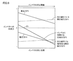
- the support rigidity of the dynamic pressure groove is proportional to the rotation speed of the impeller. Therefore, in order for the impeller to rotate stably without contacting the housing even when a disturbance is applied to the pump, it is necessary to increase the normal rotation speed range of the pump and increase the rigidity of the impeller in the axial direction.
- the support rigidity is low and the impeller cannot be rotated at a high speed. .
- Patent Document 2 an electromagnet for urging the impeller in a predetermined direction and a magnetic force adjustment coil for changing the magnetic force of the permanent magnet are provided, and these are operated when the impeller starts rotating.
- a method to make the impeller start up smoothly has also been proposed.
- such a countermeasure has a problem that the pump size is increased because a new dedicated member such as an electromagnet or a coil is required, and the reliability is lowered because the number of components increases.
- a main object of the present invention is to provide a small centrifugal pump device that can rotate an impeller at high speed and can smoothly rotate and start the impeller.
- a centrifugal pump device is provided with a housing including first and second chambers partitioned by a partition, and is rotatably provided along the partition in the first chamber.
- a centrifugal pump device provided with an impeller to be sent and a drive unit that is provided in a second chamber and rotationally drives the impeller via a partition wall, the first magnetic body provided on one surface of the impeller;
- the second magnetic body that is provided on the inner wall of the first chamber facing the one surface of the impeller and that attracts the first magnetic body and the other surface of the impeller are the same so that adjacent magnetic poles are different from each other.
- a plurality of first permanent magnets arranged along a circle.
- the drive unit is provided to face the plurality of first permanent magnets, and is provided corresponding to the plurality of third magnetic bodies each formed in a columnar shape, and the plurality of third magnetic bodies, respectively. Each includes a plurality of coils wound around a corresponding third magnetic body and generating a rotating magnetic field.
- the first attraction force between the first and second magnetic bodies and the second attraction force between the plurality of first permanent magnets and the plurality of third magnetic bodies are: It balances in the middle of the movable range of the impeller in the room.
- a first dynamic pressure groove is formed on one surface of the impeller or the inner wall of the first chamber facing it, and a second dynamic pressure groove is formed on the other surface of the impeller or a partition wall facing it.
- a third magnetic body is provided in each coil of the drive unit, and this third magnetic body and the first permanent magnet of the impeller are magnetically coupled. Therefore, by adjusting the coil current, the impeller can be The impeller can be rotated at a high speed, and the rotation starting force of the impeller can be increased while keeping the pump size small.
- the third magnetic body is formed in a columnar shape, a large space for the coil can be secured and the number of turns of the coil can be increased. Therefore, a large torque for rotating the impeller can be generated. Moreover, the copper loss which generate
- the ellipticity of the third magnetic body is determined according to the inner and outer diameter dimensions of the coil space and the number of motor slots.
- the drive unit further includes a fourth magnetic body provided on a front end surface of the third magnetic body facing the first permanent magnet.
- the area of the surface of the fourth magnetic body facing the first permanent magnet is larger than the area of the tip surface of the third magnetic body.
- the surfaces of the two adjacent fourth magnetic bodies facing each other are provided substantially parallel to each other. In this case, a large torque for rotating the impeller can be generated.
- each third magnetic body includes a plurality of steel plates stacked in the length direction of the rotation shaft of the impeller. In this case, the eddy current loss generated in the third magnetic body can be reduced, and the energy efficiency in the rotational driving of the impeller can be increased.
- each third magnetic body includes a plurality of steel plates stacked in the direction of rotation of the impeller.
- the eddy current loss generated in the third magnetic body can be reduced, and the energy efficiency in the rotational driving of the impeller can be increased.
- each third magnetic body includes a plurality of steel plates stacked in the radial direction of the impeller.
- the eddy current loss generated in the third magnetic body can be reduced, and the energy efficiency in the rotational driving of the impeller can be increased.
- each third magnetic body is made of pure iron, soft iron, or silicon iron powder.
- the iron loss in the third magnetic body can be reduced, and the energy efficiency in the rotational driving of the impeller can be increased.
- each of the first and second magnetic bodies is a permanent magnet. Further preferably, it further includes a plurality of second permanent magnets provided on the other surface of the impeller and respectively inserted into a plurality of gaps of the plurality of first permanent magnets.
- Each second permanent magnet is magnetized in the direction of rotation of the impeller.
- the first magnetic pole of each second permanent magnet is directed to the first permanent magnet side in which the first magnetic pole is directed to the partition side of the two adjacent first permanent magnets.
- the second magnetic pole of each second permanent magnet is directed to the first permanent magnet side in which the second magnetic pole is directed to the partition side of the two adjacent first permanent magnets.
- the sum of the absolute value of the negative support stiffness value in the axial direction of the impeller constituted by the first and second suction forces and the absolute value of the positive stiffness value in the radial direction of the impeller is expressed by: Is smaller than the absolute value of the positive stiffness value obtained by the first and second dynamic pressure grooves in the normal rotational speed region where the rotation speed of the motor is rotated.
- the dynamic pressure generated by the first dynamic pressure groove is different from the dynamic pressure generated by the second dynamic pressure groove.
- At least one of the first and second dynamic pressure grooves is an inward spiral groove.
- a diamond-like carbon film for reducing frictional force is formed on at least one of the impeller surface and the inner wall of the first chamber.
- the liquid is blood and the centrifugal pump device is used to circulate blood.
- the centrifugal pump device is used to circulate blood.
- the impeller can be rotated at high speed, and the rotation starting force of the impeller can be increased while keeping the pump size small. Further, the mechanical contact between the impeller and the housing can be reduced, and the impeller can be stably floated. In addition, the liquid can flow smoothly. Further, the impeller can be rotated and started smoothly. Further, a large torque for rotating the impeller can be generated. Moreover, the energy efficiency in the rotational drive of an impeller can be improved. In addition, when blood is circulated, hemolysis can be avoided.
- FIG. 3 is a sectional view taken along line III-III in FIG. 2.
- FIG. 4 is a sectional view taken along line IV-IV in FIG. 3.
- FIG. 4 is a cross-sectional view showing a state where an impeller is removed from the cross-sectional view taken along the line IV-IV in FIG.
- FIG. 4 is a cross-sectional view showing a state where an impeller is removed from the cross-sectional view taken along the line VI-VI in FIG. 3.
- FIG. 4 is a sectional view taken along line VII-VII in FIG. 3.
- FIG. 8 is a block diagram illustrating a configuration of a controller that controls the pump unit illustrated in FIGS. 1 to 7; 12 is a time chart illustrating an operation of the controller illustrated in FIG. 11.
- 6 is a block diagram showing a modification of the first embodiment.
- FIG. 10 is a time chart showing another modification of the first embodiment.
- FIG. 10 is a cross-sectional view showing still another modification example of the first embodiment.
- FIG. 10 is a cross-sectional view showing still another modification example of the first embodiment.
- FIG. 10 is a cross-sectional view showing still another modification example of the first embodiment.
- FIG. 17 is a cross-sectional view illustrating the shape of a magnetic body 35 illustrated in FIG. 16.
- FIG. 10 is a cross-sectional view showing still another modification example of the first embodiment.
- FIG. 10 is a cross-sectional view showing still another modification example of the first embodiment.
- FIG. 10 is a cross-sectional view showing still another modification example of the first embodiment.
- FIG. 10 is a cross-sectional view showing still another modification example of the first embodiment.
- FIG. 10 is a cross-sectional view showing a main part of a modification of the second embodiment.
- FIG. 10 is a diagram illustrating a modification example of the fourth embodiment. It is a figure which shows the optimal range of the area ratio of the permanent magnet 40 with respect to the permanent magnet 17 shown in FIG. It is a figure which shows the structure of the axial gap type motor by Embodiment 5 of this invention.
- FIG. 10 is a diagram showing a comparative example of the fifth embodiment. It is a figure which shows the example of a change of Embodiment 5.
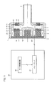
- FIG. 1 is a front view showing an appearance of a pump unit 1 of a centrifugal blood pump apparatus according to Embodiment 1 of the present invention
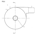
- FIG. 2 is a side view thereof
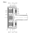
- 3 is a sectional view taken along the line III-III in FIG. 2
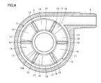
- FIG. 4 is a sectional view taken along the line IV-IV in FIG. 3
- FIG. 5 shows a state where the impeller is removed from the sectional view taken along the line IV-IV in FIG.
- It is sectional drawing. 6 is a cross-sectional view showing a state where the impeller is removed from the cross-sectional view taken along the line VI-VI in FIG. 3
- FIG. 7 is a cross-sectional view taken along the line VII-VII in FIG.
- the pump unit 1 of the centrifugal blood pump apparatus includes a housing 2 formed of a nonmagnetic material.
- the housing 2 includes a columnar main body 3, a cylindrical blood inflow port 4 erected at the center of one end surface of the main body 3, and a cylindrical blood outflow provided on the outer peripheral surface of the main body 3.
- Port 5 is included.
- the blood outflow port 5 extends in the tangential direction of the outer peripheral surface of the main body 3.
- a blood chamber 7 and a motor chamber 8 partitioned by a partition wall 6 are provided in the housing 2.
- a disc-like impeller 10 having a through hole 10a in the center is rotatably provided.
- the impeller 10 includes two shrouds 11 and 12 each having a donut plate shape and a plurality of (for example, six) vanes 13 formed between the two shrouds 11 and 12.
- the shroud 11 is disposed on the blood inlet port 4 side, and the shroud 12 is disposed on the partition wall 6 side.
- the shrouds 11 and 12 and the vane 13 are made of a nonmagnetic material.
- a plurality (six in this case) of blood passages 14 partitioned by a plurality of vanes 13 are formed between the two shrouds 11 and 12.
- the blood passage 14 communicates with the central through hole 10 a of the impeller 10, and starts from the through hole 10 a of the impeller 10 and extends so that the width gradually increases to the outer peripheral edge.
- the vane 13 is formed between two adjacent blood passages 14.
- the plurality of vanes 13 are provided at equiangular intervals and formed in the same shape. Therefore, the plurality of blood passages 14 are provided at equiangular intervals and are formed in the same shape.
- the blood flowing in from the blood inflow port 4 is sent from the through hole 10a to the outer periphery of the impeller 10 through the blood passage 14 by the centrifugal force and flows out from the blood outflow port 5.
- a permanent magnet 15 is embedded in the shroud 11
- a permanent magnet 16 that attracts the permanent magnet 15 is embedded in the inner wall of the blood chamber 7 facing the shroud 11.
- the permanent magnets 15 and 16 are provided for attracting (in other words, energizing) the impeller 10 on the side opposite to the motor chamber 8, in other words, on the blood inflow port 4 side.
- a permanent magnet may be provided on one of the inner walls of the shroud 11 and the blood chamber 7, and a magnetic material may be provided on the other.
- a magnetic material may be provided on the other.
- the magnetic material either a soft magnetic material or a hard magnetic material may be used.
- the permanent magnet 16 may be one or plural.
- the permanent magnet 16 is formed in a ring shape.
- the plurality of permanent magnets 16 are arranged along the same circle at equal angular intervals.
- the permanent magnet 15 is the same as the permanent magnet 16, and may be one or plural.
- a plurality (for example, eight) of permanent magnets 17 are embedded in the shroud 12.
- the plurality of permanent magnets 17 are arranged along the same circle at equal angular intervals so that adjacent magnetic poles are different from each other.
- the permanent magnets 17 with the N pole facing the motor chamber 8 side and the permanent magnets 17 with the S pole facing the motor chamber 8 side are alternately arranged along the same circle at equal angular intervals. .
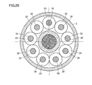
- a plurality of (for example, nine) magnetic bodies 18 are provided in the motor chamber 8.
- the plurality of magnetic bodies 18 are arranged along the same circle at equal angular intervals so as to face the plurality of permanent magnets 17 of the impeller 10.
- the base ends of the plurality of magnetic bodies 18 are joined to one disk-shaped yoke 19.
- a coil 20 is wound around each magnetic body 18.
- each of the plurality of magnetic bodies 18 is formed in a cylindrical shape, and the plurality of magnetic bodies 18 have the same dimensions.
- the end face on the base end side of the cylindrical magnetic body 18 is joined to the yoke 19, and the end face on the front end side faces the plurality of permanent magnets 17 of the impeller 10 through the partition wall 6.
- a space for winding the coil 20 is evenly secured around the plurality of magnetic bodies 18.
- the magnetic body 18 is often formed in a triangular prism shape or a fan shape.
- the surfaces of the two adjacent magnetic bodies 18 facing each other can be made substantially parallel, and adjacent coils 20 interfere with each other to reduce the winding volume. This is because it can be prevented.
- the magnetic body 18 is preferably cylindrical.
- the length of the conductive wire of the coil 20 is greater when the coil 20 is wound around the cylindrical magnetic body 18.
- the resistance value of the coil 20 can be reduced. That is, the copper loss generated in the coil 20 can be reduced, and the energy efficiency in the rotational drive of the impeller 10 can be increased.
- the outer surface surrounding the plurality of magnetic bodies 18 is the outer surface surrounding the plurality of permanent magnets 17 (the outer periphery of the plurality of permanent magnets 17 in FIG. 4).
- the outer surface surrounding the plurality of magnetic bodies 18 may be larger than the outer surface surrounding the plurality of permanent magnets 17.
- the magnetic body 18 is designed so that there is no magnetic saturation at the maximum rating of the pump 1 (the condition that the rotational driving torque of the impeller 10 is maximum).
- the voltage is applied to the nine coils 20 by, for example, a 120-degree energization method. That is, nine coils 20 are grouped by three. Voltages VU, VV, and VW as shown in FIG. 8 are applied to the first to third coils 20 of each group. A positive voltage is applied to the first coil 20 during a period of 0 to 120 degrees, 0 V is applied during a period of 120 to 180 degrees, a negative voltage is applied during a period of 180 to 300 degrees, and 300 to 360 degrees. 0V is applied during this period.
- the front end surface (end surface on the impeller 10 side) of the magnetic body 18 around which the first coil 20 is wound becomes the N pole in the period of 0 to 120 degrees and becomes the S pole in the period of 180 to 300 degrees.
- the phase of the voltage VV is 120 degrees behind the voltage VU
- the phase of the voltage VW is 120 degrees behind the voltage VV. Therefore, by applying the voltages VU, VV, and VW to the first to third coils 20, respectively, a rotating magnetic field can be formed, and the magnetic elements 18 and the permanent magnets 17 of the impeller 10 are attracted to each other.
- the impeller 10 can be rotated by the force and the repulsive force.
- the impeller 10 rotates at the rated rotational speed, the attractive force between the permanent magnets 15 and 16 and the attractive force between the plurality of permanent magnets 17 and the plurality of magnetic bodies 18 are within the blood chamber 7.
- the impeller 10 is balanced near the approximate center of the movable range. For this reason, in any movable range of the impeller 10, the acting force due to the suction force to the impeller 10 is very small. As a result, the frictional resistance at the time of relative sliding between the impeller 10 and the housing 2 generated when the impeller 10 starts rotating can be reduced.
- a plurality of dynamic pressure grooves 21 are formed on the surface of the partition wall 6 facing the shroud 12 of the impeller 10, and a plurality of dynamic pressure grooves 22 are formed on the inner wall of the blood chamber 7 facing the shroud 11.
- a dynamic pressure bearing effect is generated between each of the dynamic pressure grooves 21 and 22 and the impeller 10.
- a drag force is generated from each of the dynamic pressure grooves 21 and 22 against the impeller 10, and the impeller 10 rotates in a non-contact state in the blood chamber 7.
- the plurality of dynamic pressure grooves 21 are formed in a size corresponding to the shroud 12 of the impeller 10, as shown in FIG.
- Each dynamic pressure groove 21 has one end on the periphery (circumference) of a circular portion slightly spaced from the center of the partition wall 6 and has a width up to the vicinity of the outer edge of the partition wall 6 in a spiral shape (in other words, curved). It extends to gradually spread.
- the plurality of dynamic pressure grooves 21 have substantially the same shape and are arranged at substantially the same interval.
- the dynamic pressure groove 21 is a recess, and the depth of the dynamic pressure groove 21 is preferably about 0.005 to 0.4 mm.
- the number of the dynamic pressure grooves 21 is preferably about 6 to 36.
- ten dynamic pressure grooves 21 are arranged at an equal angle with respect to the central axis of the impeller 10. Since the dynamic pressure groove 21 has a so-called inward spiral groove shape, when the impeller 10 rotates in the clockwise direction, the liquid pressure increases from the outer diameter portion to the inner diameter portion of the dynamic pressure groove 21. For this reason, a repulsive force is generated between the impeller 10 and the partition wall 6, and this becomes a dynamic pressure.
- the dynamic pressure groove 21 may be provided on the surface of the shroud 12 of the impeller 10 instead of providing the dynamic pressure groove 21 in the partition wall 6.
- the impeller 10 is separated from the partition wall 6 and rotates in a non-contact state. For this reason, a blood flow path is ensured between the impeller 10 and the partition 6, and the blood retention between both and the generation
- the corner portion of the dynamic pressure groove 21 is preferably rounded so as to have an R of at least 0.05 mm. Thereby, generation
- the plurality of dynamic pressure grooves 22 are formed in a size corresponding to the shroud 11 of the impeller 10 as with the plurality of dynamic pressure grooves 21.
- Each dynamic pressure groove 22 has one end on the periphery (circumference) of a circular portion slightly spaced from the center of the inner wall of the blood chamber 7, and is spirally (in other words, curved) on the inner wall of the blood chamber 7. It extends so that the width gradually increases to the vicinity of the outer edge.
- the plurality of dynamic pressure grooves 22 have substantially the same shape and are arranged at substantially the same interval.
- the dynamic pressure groove 22 is a recess, and the depth of the dynamic pressure groove 22 is preferably about 0.005 to 0.4 mm.
- the number of the dynamic pressure grooves 22 is preferably about 6 to 36. In FIG. 6, ten dynamic pressure grooves 22 are arranged at an equal angle with respect to the central axis of the impeller 10.
- the dynamic pressure groove 22 may be provided not on the inner wall side of the blood chamber 7 but on the surface of the shroud 11 of the impeller 10. Further, the corners of the dynamic pressure grooves 22 are preferably rounded so as to have an R of at least 0.05 mm. Thereby, generation
- the impeller 10 is separated from the inner wall of the blood chamber 7 and rotates in a non-contact state. Moreover, when the pump part 1 receives an external impact or when the dynamic pressure by the dynamic pressure groove 21 becomes excessive, it is possible to prevent the impeller 10 from sticking to the inner wall of the blood chamber 7.
- the dynamic pressure generated by the dynamic pressure groove 21 and the dynamic pressure generated by the dynamic pressure groove 22 may be different.
- the impeller 10 rotates in a state in which the gap between the shroud 12 of the impeller 10 and the partition wall 6 and the gap between the shroud 11 of the impeller 10 and the inner wall of the blood chamber 7 are substantially the same.
- the dynamic pressure by the dynamic pressure groove on the narrowing side is made larger than the dynamic pressure by the other dynamic pressure groove, To make the dynamic pressure grooves 21 and 22 different in shape.
- each of the dynamic pressure grooves 21 and 22 has an inward spiral groove shape, but other shapes of the dynamic pressure grooves 21 and 22 can also be used. However, when blood is circulated, it is preferable to employ the inward spiral groove-shaped dynamic pressure grooves 21 and 22 that allow blood to flow smoothly.
- the attraction force F1 between the permanent magnets 15 and 16 is set smaller than the attraction force F2 between the permanent magnet 17 and the magnetic body 18, and the floating position of the impeller 10 at which the resultant force becomes zero is from the middle of the impeller movable range. Is also on the partition wall 6 side.
- the shapes of the dynamic pressure grooves 21 and 22 are the same.
- the acting force on the impeller 10 includes an attractive force F1 between the permanent magnets 15 and 16, an attractive force F2 between the permanent magnet 17 and the magnetic body 18, a dynamic pressure F3 in the dynamic pressure groove 21, and a dynamic force in the dynamic pressure groove 22.
- the pressure F4 and the resultant force “net force F5 acting on the impeller” are shown.
- FIG. 10 shows that the magnitude of the resultant force between the attractive force F1 between the permanent magnets 15 and 16 and the attractive force F2 between the permanent magnet 17 and the magnetic body 18 is the movable range in the blood chamber 7 of the impeller 10. It is a figure which shows the force which acts on the impeller 10 when it adjusts so that it may become zero in the center position P0. Also in this case, the rotational speed of the impeller 10 is kept at the rated value.
- the attractive force F1 between the permanent magnets 15 and 16 and the attractive force F2 between the permanent magnet 17 and the magnetic body 18 are set to be substantially the same. Further, the shapes of the dynamic pressure grooves 21 and 22 are the same. In this case, the support rigidity with respect to the floating position of the impeller 10 is higher than in the case of FIG. Since the net force F5 acting on the impeller 10 is zero at the center of the movable range, the impeller 10 floats at the center position when no disturbance force acts on the impeller 10.
- the floating position of the impeller 10 is generated in the dynamic pressure grooves 21 and 22 when the impeller 10 rotates, and the attractive force F1 between the permanent magnets 15 and 16, the attractive force F2 between the permanent magnet 17 and the magnetic body 18, and the impeller 10. It is determined by the balance with dynamic pressures F3 and F4.
- F1 and F2 substantially the same and making the shape of the dynamic pressure grooves 21 and 22 the same
- the impeller 10 can be floated at the substantially central portion of the blood chamber 7 when the impeller 10 rotates.
- the impeller 10 has a shape in which blades are formed between two disks. Therefore, two surfaces facing the inner wall of the housing 2 can have the same shape and the same size. Therefore, it is possible to provide the dynamic pressure grooves 21 and 22 having substantially the same dynamic pressure performance on both sides of the impeller 10.
- the two dynamic pressure grooves 21 and 22 have the same shape.
- the dynamic pressure grooves 21 and 22 have different shapes, and the dynamic pressure grooves 21 and 22
- the pressure performance may be different. For example, when a disturbance in one direction always acts on the impeller 10 due to fluid force or the like during pumping, the performance of the dynamic pressure groove in the direction of the disturbance is made higher than the performance of the other dynamic pressure groove. As a result, the impeller 10 can be floated and rotated at the center position of the housing 2. As a result, the contact probability between the impeller 10 and the housing 2 can be kept low, and the stable flying performance of the impeller 10 can be obtained.
- the absolute value of the negative support rigidity value in the axial direction of the impeller 10 constituted by the attractive force F1 between the permanent magnets 15 and 16 and the attractive force F2 between the permanent magnet 17 and the magnetic body 18 is defined as Ka. If the absolute value of the radial positive stiffness value is Kr, and the absolute value of the positive stiffness value obtained by the two dynamic pressure grooves 21 and 22 is Kg in the normal rotational speed region where the impeller 10 rotates, Kg> Ka + Kr It is preferable to satisfy the relationship.
- the absolute value Kg of the positive stiffness value obtained by the two dynamic pressure grooves 21 and 22 is set to a value exceeding 30000 N / m.
- the axial support rigidity of the impeller 10 is a value obtained by subtracting the negative rigidity due to the attractive force between the magnetic bodies from the rigidity caused by the dynamic pressure generated in the dynamic pressure grooves 21 and 22, it has a relationship of Kg> Ka + Kr.
- the support rigidity in the axial direction can be higher than the support rigidity in the radial direction of the impeller 10.
- the impeller 10 swings during rotation. This swing depends on the natural frequency determined by the mass of the impeller 10 and the support rigidity value of the impeller 10 and the rotational speed of the impeller 10. Maximum if matched.
- the support rigidity in the radial direction is smaller than the support rigidity in the axial direction of the impeller 10. Therefore, it is preferable to set the maximum rotational speed of the impeller 10 to be equal to or less than the natural frequency in the radial direction. Therefore, in order to prevent mechanical contact between the impeller 10 and the housing 2, the radial rigidity value of the impeller 10 constituted by the attractive force F1 between the permanent magnets 15 and 16 and the attractive force F2 between the permanent magnet 17 and the magnetic body 18 is set.
- the maximum rotation speed of the impeller 10 is set to 258 rad / s (2465 rpm) or less.
- the maximum rotation speed of the impeller 10 is set to 366 rad / s (3500 rpm)
- the radial rigidity is set to 4018 N / m or more.
- the maximum rotation speed of the impeller 10 it is preferable to set the maximum rotation speed of the impeller 10 to 80% or less of this ⁇ . Specifically, when the mass of the impeller 10 is 0.03 kg and the radial rigidity value is 2000 N / m, the maximum rotational speed is set to 206.4 rad / s (1971 rpm) or less. Conversely, when the maximum rotational speed of the impeller 10 is desired to be 366 rad / s (3500 rpm), the radial rigidity value is set to 6279 N / m or more. By setting the maximum rotation speed of the impeller 10 in this way, contact between the impeller 10 and the housing 2 during rotation of the impeller 10 can be suppressed.
- the dynamic pressure grooves 21 and 22 have a negative rigidity value in the axial direction of the impeller 10 constituted by the attractive force F1 between the permanent magnets 15 and 16 and the attractive force F2 between the permanent magnet 17 and the magnetic body 18.
- the impeller 10 and the housing 2 are not in contact with each other. Therefore, it is preferable to make this negative rigidity value as small as possible. Therefore, in order to keep the negative rigidity value small, it is preferable to make the sizes of the opposed surfaces of the permanent magnets 15 and 16 different.
- the rate of change of the attractive force that changes depending on the distance between them, that is, the negative stiffness can be kept small, and the impeller support stiffness is prevented from being lowered. Can do.
- impeller 10 it is preferable to rotate the impeller 10 after confirming that the impeller 10 is in contact with the partition wall 6 before the impeller 10 starts rotating.
- the shroud 12 of the impeller 10 when the shroud 12 of the impeller 10 is in contact with the partition wall 6, compared with the case where the shroud 11 of the impeller 10 is in contact with the inner wall of the blood chamber 7, the permanent magnet 17 of the impeller 10 and the motor chamber 8 Since the magnetic body 18 is close, the rotational torque at the time of starting the impeller 10 can be increased, and the impeller 10 can be rotated and started smoothly.
- the attractive force F1 between the permanent magnets 15 and 16 and the attractive force F2 between the permanent magnet 17 and the magnetic body 18 are such that the position of the impeller 10 is within the movable range of the impeller 10. Since it is set so as to be balanced in the vicinity of the center, the impeller 10 is not necessarily in contact with the partition wall 6 when the impeller 10 is stopped.
- this centrifugal blood pump device is provided with means for moving the impeller 10 toward the partition wall 6 before the impeller 10 is rotationally activated. Specifically, current is passed through the plurality of coils 20 so that the attractive force F2 between the permanent magnet 17 and the magnetic body 18 is increased, and the impeller 10 is moved to the partition wall 6 side.
- FIG. 11 is a block diagram showing the configuration of the controller 25 that controls the pump unit 1.
- the controller 25 includes a motor control circuit 26 and a power amplifier 27.
- the motor control circuit 26 outputs a three-phase control signal of, for example, a 120-degree energization method.
- the power amplifier 27 amplifies the three-phase control signal from the motor control circuit 26 to generate the three-phase voltages VU, VV, and VW shown in FIG.
- Three-phase voltages VU, VV, and VW are applied to first to third coils 20 described with reference to FIGS. 7 and 8, respectively. Accordingly, during normal operation, the impeller 10 rotates at a predetermined rotational speed at the center position of the movable range.
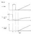
- 12 (a) to 12 (c) are time charts showing temporal changes in the coil current I, the position of the impeller 10 and the rotational speed of the impeller 10 when the impeller 10 starts rotating.
- 12A to 12C in the initial state, the shroud 11 of the impeller 10 is in contact with the inner wall of the blood chamber 7 by the attractive force of the permanent magnets 15 and 16, and the impeller 10 is at the position PA. To do. In this state, since the impeller 10 is difficult to rotate, the impeller 10 is moved to a position PB where the shroud 12 of the impeller 10 contacts the partition wall 6.
- the voltage of any one of the six patterns (0 to 60 degrees, 60 to 120 degrees,..., 300 to 360 degrees) of voltages VU, VV, and VW shown in FIG. 3 is applied to the coil 20, and a predetermined current I 0 is passed through the coil 20.
- the attractive force F2 between the permanent magnet 17 and the magnetic body 18 becomes larger than the attractive force F1 between the permanent magnets 15 and 16, and the impeller 10 is hardly rotated and positioned on the partition wall 6 side.
- the shroud 12 of the impeller 10 contacts the partition wall 6.
- the current I0 is cut off (time t1).
- the impeller 10 is moved without rotating, even if the impeller 10 is moved to the position PB on the partition 6 side while rotating, the impeller 10 is prevented from moving due to the hydrodynamic bearing effect of the hydrodynamic groove 21. Because. In addition, it is preferable to provide a sensor for detecting the position of the impeller 10 in the blood chamber 7 and to cut off the current I 0 after confirming that the impeller 10 has contacted the partition wall 6.
- the impeller 10 rotates slightly (strictly speaking, 1/4 rotation or less, that is, 360 degrees or less in electrical angle), and moves to the position PB on the partition wall 6 side.
- FIG. 13 is a block diagram showing a modification of the first embodiment.
- the power source is switched when the impeller 10 starts rotating and thereafter. That is, in FIG. 13, in this modified example, the power amplifier 27 of FIG. 11 is replaced with power amplifiers 30 and 31 and a changeover switch 32. From time t0 to t1 in FIG. 12, the output signal of the motor control circuit 26 is given to the power amplifier 30, the output voltage of the power amplifier 30 is applied to the coil 20 via the changeover switch 32, and the current I0 flows through the coil 20. It is. After time t2, the output signal of the motor control circuit 26 is given to the power amplifier 31, the output voltage of the power amplifier 31 is applied to the coil 20 via the changeover switch 32, and a current flows through the coil 20.
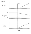
- FIGS. 14A to 14C are time charts showing another modification of the first embodiment. 14A to 14C, it is assumed that the shroud 11 of the impeller 10 is in contact with the inner wall of the blood chamber 7 in the initial state, and the impeller 10 is at the position PA.
- a predetermined current I1 is passed through the coil 20 at time t0. That is, the motor control circuit 26 generates, for example, a 120-degree energization type three-phase control signal.
- the power amplifier 27 amplifies the three-phase control signal from the motor control circuit 26 to generate the three-phase voltages VU, VV, and VW shown in FIG. Three-phase voltages VU, VV, and VW are applied to first to third coils 20 described with reference to FIGS. 7 and 8, respectively.
- This current I1 is larger than the current I0 in FIG. 12 and is a current that can rotate the impeller 10 even when the shroud 11 of the impeller 10 is in contact with the inner wall of the blood chamber 7.
- the coil current I is reduced and gradually increased to a predetermined rated value. In this way, even when the impeller 10 is on the position PA side, an excessive current may be supplied to the coil 20 only when the impeller 10 starts to rotate.
- a diamond-like carbon (DLC) film may be formed on at least one of the inner wall surface of the blood chamber 7 and the surface of the partition wall 6 and the surface of the impeller 10. Thereby, the frictional force between the impeller 10 and the inner wall of the blood chamber 7 and the partition wall 6 can be reduced, and the impeller 10 can be smoothly rotated and started.
- a fluorine-based resin film, a paraxylylene-based resin film, or the like may be formed instead of the diamond-like carbon film.
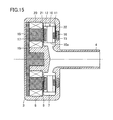
- FIG. 15 is a cross-sectional view showing still another modified example of the first embodiment, and is a diagram contrasted with FIG.
- the sizes of the opposing surfaces of the opposing permanent magnets 15 and 16 are different.
- FIG. 3 shows a case where the sizes of the opposing surfaces of the permanent magnets 15 and 16 are the same.
- the amount of change in force that is, negative rigidity can be suppressed to a small value, and a decrease in the support rigidity of the impeller 10 can be prevented.
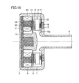
- FIG. 16 is a cross-sectional view showing still another modified example of the first embodiment, and is a view compared with FIG.
- a magnetic body 35 is provided on the tip surface of each magnetic body 18 facing the permanent magnet 17.
- the area of the surface of the magnetic body 35 facing the permanent magnet 17 is larger than the area of the tip surface of the magnetic body 18.
- the surface of the magnetic body 35 facing the permanent magnet 17 is preferably triangular or fan-shaped.
- the magnetic body 18 is often formed in a triangular prism shape or a fan shape, and the front end surface of the magnetic body 18 is not provided with the magnetic body 35.
- the permanent magnet 17 are often directly opposed to the permanent magnet 17.
- a magnetic flux for generating torque can be uniformly applied to the magnetic pole switching line (boundary line between the N pole and the S pole) of the permanent magnet 17.
- the motor structure can be simplified and the number of parts can be reduced if the tip surface of the magnetic body 18 is directly opposed to the permanent magnet 17 without providing the magnetic body 35.
- the cylindrical magnetic body 18 is used to reduce the copper loss of the coil 20 and increase the motor efficiency.
- the efficiency of the torque generating magnetic flux with respect to the magnetic pole switching line (the boundary line between the N pole and the S pole) of the permanent magnet 17 becomes low.
- the energy efficiency in the rotational drive of the impeller 10 cannot be increased.
- the pump device of the first embodiment it is necessary to precisely adjust the balance between the attractive force generated on the permanent magnets 15 and 16 side and the attractive force generated on the permanent magnet 17 side.
- the attractive force value largely depends on the facing area of the magnetic body 18 and the permanent magnet 17. If the cross-sectional area of the magnetic body 18 is changed in order to adjust the attractive force value, the coil 20 needs to be rewound and the motor body reassembled each time the change is made, which increases labor.
- FIG. 18 is a cross-sectional view showing still another modification of the first embodiment, and is a view contrasted with FIG.
- the yoke 19 is replaced with the yoke 36
- the magnetic body 18 is replaced with the magnetic body 37.
- Each of the yoke 36 and the magnetic body 37 includes a plurality of steel plates stacked in the length direction of the rotation shaft of the impeller 10.
- the eddy current loss generated in the yoke 36 and the magnetic body 37 can be reduced, and the energy efficiency in the rotational drive of the impeller 10 can be increased.
- the magnetic body 37 may be replaced with a magnetic body 38 including a plurality of steel plates stacked in the rotation direction of the impeller 10.
- the magnetic body 37 may be replaced with a magnetic body 39 including a plurality of steel plates stacked in the radial direction of the impeller 10. Even in these cases, the same effect as the modified example of FIG. 18 is obtained.
- each of the yoke 19 and the magnetic body 18 in FIG. 3 may be formed of pure iron, soft iron, or silicon iron powder. In this case, the iron loss of the yoke 19 and the magnetic body 18 can be reduced, and the energy efficiency in the rotational drive of the impeller 10 can be improved.
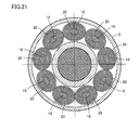
- FIG. 21 is a cross-sectional view showing still another modified example of the first embodiment, which is compared with FIG.
- the cross-sectional shape of the magnetic body 18 when the magnetic body 18 is cut along a plane perpendicular to the axial direction of the magnetic body 18 is an ellipse. That is, the cross-sectional shape of the magnetic body 18 is not limited to a perfect circle, and may be an ellipse with an ellipticity of 0.5 or more. However, the ellipticity is a ratio (short diameter / major diameter) of the short axis (length of the short axis) and the long diameter (length of the long axis) of the ellipse.
- the ellipticity of the magnetic body 18 is determined according to the size of the inner and outer diameters of the space for the coil 20 and the number of slots of the motor.
- the plurality of magnetic bodies 18 are arranged at equiangular intervals along the same circle. As shown in FIG. 21, the major axis of the ellipse may be oriented in the tangential direction of the circle, and as shown in FIG. 22, the minor axis of the ellipse may be oriented in the tangential direction of the circle. Even in these modified examples, since the outer peripheral surface of the magnetic body 18 has no corners, the coil 20 can be easily wound and a large space for the coil 20 can be secured.
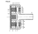
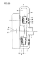
- FIG. 23 is a cross-sectional view showing a configuration of a pump portion of a centrifugal blood pump apparatus according to Embodiment 2 of the present invention, and is a view compared with FIG.
- permanent magnets 15a and 15b are embedded in the shroud 11
- permanent magnets 16a and 16b for attracting the permanent magnets 15a and 15b are embedded in the inner wall of the blood chamber 7 facing the shroud 11, respectively. Yes.
- Each of the permanent magnets 15a and 15b is formed in an annular shape, and the outer diameter of the permanent magnet 15a is smaller than the inner diameter of the permanent magnet 15b.
- the permanent magnets 15 a and 15 b are provided coaxially, and the center points of the permanent magnets 15 a and 15 b are both arranged on the rotation center line of the impeller 10. In the figure, the end faces in the same direction of the permanent magnets 15a and 15b have different polarities, but they may have the same polarity.
- each of the permanent magnets 16a and 16b is formed in an annular shape, and the outer diameter and inner diameter of the permanent magnet 16a are the same as the outer diameter and inner diameter of the permanent magnet 15a.
- the outer diameter and inner diameter of the permanent magnet 16b are the same as the outer diameter and inner diameter of the permanent magnet 15b.
- the permanent magnets 16 a and 16 b are provided coaxially, and the center points of the permanent magnets 16 a and 16 b are both arranged on the center line of the cylindrical side wall of the blood chamber 7. In the figure, the end faces in the same direction of the permanent magnets 16a and 16b have different polarities, but they may have the same polarity.
- the permanent magnets 15a and 16a and the permanent magnets 15b and 16b are opposed to each other in a pole arrangement for attracting each other.
- the distance D1 between the permanent magnets 15a and 15b is a radial movable distance of the impeller 10 (that is, the distance between the inner diameter of the blood chamber 7 and the outer diameter of the impeller 10).
- the distance D2 is set to be larger than the half distance D2 (D1> D2). This is because when D1 ⁇ D2, when the impeller 10 moves to the maximum in the radial direction, the permanent magnets 15a and 16b and the permanent magnets 15b and 16a interfere with each other to restore the impeller 10 to the pump center position. Because it becomes unstable.
- the radial movable distance of impeller 10 is the difference between the inner diameter of the protrusion on the inner wall of blood chamber 7 and the outer diameter of impeller 10.
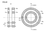
- FIGS. 24 (a) and 24 (b) are diagrams showing a main part of a modification of the second embodiment, and showing the configuration of the permanent magnets 15a, 15b, 16a, 16b.
- FIG. 24A is a cross-sectional view taken along the line XXIVA-XXIVA of FIG.
- each of the permanent magnets 15a and 15b is formed in an annular shape, and the outer diameter of the permanent magnet 15a is smaller than the inner diameter of the permanent magnet 15b.
- each of the permanent magnets 16 a and 16 b is formed in an arc shape, and two are arranged in the rotation direction of the impeller 10.
- the outer diameter and inner diameter of the two permanent magnets 16a arranged in an annular shape are the same as the outer diameter and inner diameter of the permanent magnet 15a.
- the outer diameter and inner diameter of the two permanent magnets 16b arranged in an annular shape are the same as the outer diameter and inner diameter of the permanent magnet 15b. Even in this modified example, the same effect as in the second embodiment can be obtained.
- FIG. 25 shows a state where the rotation center line L2 of the impeller 10 has moved to the opening 7a side by a certain distance R from the center line L1 of the cylindrical side wall of the blood chamber 7. Moreover, the state in which the partition wall 6 and the impeller 10 are not parallel, and the plane including the partition wall 6 and the plane including the center surface of the impeller 10 intersect at an angle ⁇ on the opposite side of the opening 7a is shown. Yes.
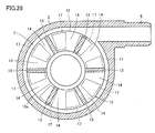
- FIG. 26 is a diagram showing a positional relationship between the center line L1 of the side wall of the blood chamber 7 and the opening 7a.
- the housing 2 is cut along a plane that is orthogonal to the center line L 1 of the side wall of the blood chamber 7 and includes the center line of the hole of the blood outflow port 5.
- the side wall of the blood chamber 7 is formed along a circle C on the plane.
- the center point of the circle C is the intersection of the plane and the center line L 1 of the side wall of the blood chamber 7.
- the hole of the blood outflow port 5 extends in the tangential direction of the circle C.
- the impeller 10 rotates in the direction of rotation of the clock hand, and the blood also rotates in that direction.
- the hole P of the blood outflow port 5 and the contact point P of the circle C are located at the end on the upstream side (left side in FIG. 26) of the opening 7 a on the side wall of the blood chamber 7.
- the direction of the contact P (upstream end of the opening 7a) as viewed from the center point of the circle C (center line L1 of the side wall of the blood chamber 7) is 0 degree, and the opposite direction is 180 degrees.
- the impeller 10 floats at a position where the fluid force of blood, the dynamic pressure of the hydrodynamic bearing, the attractive force of the permanent magnets 15a and 15b and the permanent magnets 16a and 16b, the permanent magnet 17 on the impeller 10 side and the magnetic body 18 on the motor side. It is determined by the balance such as suction force.
- the permanent magnets 15a, 15b and the permanent magnets on the opening 7a side are made permanent.
- the attractive force of the magnets 16a and 16b is set smaller than the attractive force of the permanent magnets 15a and 15b and the permanent magnets 16a and 16b on the opposite side of the opening 7a.
- a degree is a predetermined angle larger than 0 degree and smaller than 180 degrees.
- the A degree is 60 degrees.
- FIG. 27 (a) and 27 (b) are diagrams showing the configuration of the permanent magnets 15a, 15b, 16a and 16b
- FIG. 27 (a) is a cross-sectional view taken along the line XXVIIA-XXVIIA in FIG. 27 (b).
- 27A and 27B show a state in which the center line L1 of the cylindrical side wall of the blood chamber 7 and the rotation center line L2 of the impeller 10 coincide with each other.
- Each of the permanent magnets 15a and 15b is formed in an annular shape, and the outer diameter of the permanent magnet 15a is smaller than the inner diameter of the permanent magnet 15b.
- the permanent magnets 15 a and 15 b are provided coaxially, and the center points of the permanent magnets 15 a and 15 b are both disposed on the rotation center line L ⁇ b> 2 of the impeller 10.
- the N poles of the permanent magnets 15a and 15b are directed in opposite directions.
- each of the permanent magnets 16a and 16b is also formed in an annular shape.
- the outer diameter and inner diameter of the permanent magnet 16a are the same as the outer diameter and inner diameter of the permanent magnet 15a.
- the outer diameter and inner diameter of the permanent magnet 16b are the same as the outer diameter and inner diameter of the permanent magnet 15b.
- the permanent magnets 16 a and 16 b are provided coaxially, and the center points of the permanent magnets 16 a and 16 b are both disposed on the center line L 1 of the cylindrical side wall of the blood chamber 7.
- the N poles of the permanent magnets 16a and 16b are directed in different directions.
- the S poles of the permanent magnets 15a and 15b and the N poles of the permanent magnets 16a and 16b are opposed to each other.
- the attractive force of the permanent magnets 15a and 15b and the permanent magnets 16a and 16b on the opening 7a side is expressed by the permanent magnet 15a on the opposite side of the opening 7a.
- 15b and the permanent magnets 16a, 16b, the permanent magnets 16a, 16b on the opening 7a side are made thinner.
- a degree is a predetermined angle larger than 0 degree and smaller than 180 degrees.
- the A degree is 60 degrees.
- the back surface of the permanent magnets 16a and 16b (the surface opposite to the surface facing the permanent magnets 15a and 15b) has a predetermined depth. A recess is formed.
- the attractive force of the permanent magnets 15a, 15b and the permanent magnets 16a, 16b on the opening 7a side is made smaller than the attractive force of the permanent magnets 15a, 15b and the permanent magnets 16a, 16b on the opposite side of the opening 7a,
- the impeller 10 can be parallel to the partition wall 6 during rotation, and the impeller 10 can be prevented from contacting the inner wall of the blood chamber 7.
- the predetermined portions of the permanent magnets 16a and 16b are thinned in order to suppress the inclination (angle ⁇ ) with respect to the rotation axis of the impeller 10.
- the present invention is not limited to this, and the permanent magnets 16a and 16b are not limited thereto.
- a cutout may be made in the outer peripheral portion of the predetermined portion, the width of the predetermined portion may be narrowed, the predetermined portion may be omitted, or the predetermined portion may be chamfered.
- FIG. 28 is a cross-sectional view showing the main part of a centrifugal blood pump apparatus according to Embodiment 4 of the present invention, and is a view compared with FIG.
- a plurality of permanent magnets 17 are arranged with gaps along the same circle at equal angular intervals so that adjacent magnetic poles are different from each other.
- the permanent magnet 17 with the N pole facing the motor chamber 8 side and the permanent magnet 17 with the S pole facing the motor chamber 8 side are alternately arranged along the same circle with a gap at equal angular intervals. Has been placed.
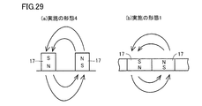
- FIG. 29 (a) is a diagram showing the magnetic field between the permanent magnets 17 and 17 in the fourth embodiment
- FIG. 29 (b) is a diagram showing the magnetic field between the permanent magnets 17 and 17 in the first embodiment.
- the magnetic flux density between the permanent magnets 17 and 17 is as follows.
- the fourth embodiment is larger, and the magnetic field around the permanent magnet 17 is stronger in the fourth embodiment. Therefore, in the fourth embodiment, the magnetic coupling force between the permanent magnet 17 of the impeller 10 and the magnetic body 18 and the coil 20 in the motor chamber 8 can be increased. Therefore, it is possible to increase the rotational torque of the impeller 10 while keeping the apparatus size small.
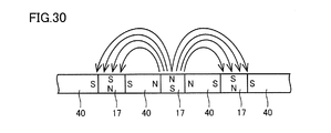
- FIG. 30 is a diagram illustrating a modification of the fourth embodiment.
- a plurality of permanent magnets 17 and a plurality of permanent magnets 40 are embedded in the shroud 12.
- the number of permanent magnets 40 is the same as the number of permanent magnets 17.
- the permanent magnet 40 is magnetized in the circumferential direction (the rotation direction of the impeller 10).
- the plurality of permanent magnets 17 and the plurality of permanent magnets 40 are alternately arranged in a Halbach array structure along the same circle at equal angular intervals.
- the permanent magnet 17 with the N pole facing the partition wall 6 side and the permanent magnet 17 with the S pole facing the partition wall 6 side are alternately arranged along the same circle with gaps provided at equal angular intervals.
- the N pole of each permanent magnet 40 is arranged toward the permanent magnet 17 with the N pole facing the partition 6 side
- the S pole of each permanent magnet 40 is arranged toward the permanent magnet 17 with the S pole facing the partition 6 side. Is done.
- the shapes of the plurality of permanent magnets 17 are the same, and the shapes of the plurality of permanent magnets 40 are the same.
- the shape of the permanent magnet 17 and the shape of the permanent magnet 40 may be the same or different.
- the attractive force between the permanent magnet 17 and the magnetic body 18 can be suppressed, and the magnetic flux causing torque can be increased, so that the permanent magnet can be most miniaturized. That is, the impeller 10 can be most lightweight and energy efficiency can be increased even when the motor gap is wide.
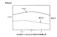
- FIG. 31 shows the relationship between the attractive force and the generated torque when the total weight of the permanent magnet 17 and the permanent magnet 40 is the same and the area ratio of the permanent magnet 40 to the permanent magnet 17 is changed.
- the area ratio of the permanent magnet 40 to the permanent magnet 17 is set in a range of 1/2 or more and 2 or less, the attraction force of the permanent magnet 17 and the magnetic body 18 is suppressed to be small while the impeller 10 The rotational torque can be increased. Therefore, the area ratio of the permanent magnet 40 to the permanent magnet 17 is optimally in the range of 1/2 or more and 2 or less.
- the area ratio between the permanent magnet 17 and the permanent magnet 40 is set to about 5: 1 to 3: 1.
- the area ratio of the permanent magnet 17 and the permanent magnet 40 is set in a range from 2: 1 to 1: 2 according to the motor size and the motor gap. Can be optimized.
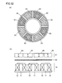
- FIG. 32 (a) is a bottom view of the rotor 61 of the axial gap motor according to the fifth embodiment of the present invention as viewed from the partition wall 60 side
- FIG. 32 (b) is a front view showing the main part of the axial gap motor.
- this axial gap type motor has the same configuration as that of the pump unit 1 of the centrifugal blood pump apparatus according to the first to fourth embodiments, and is divided into a first partition partitioned by a circular partition wall 60. And a second chamber (not shown).
- An annular rotor 61 that is rotatably provided along the partition wall 60 is provided in the first chamber, and a stator 70 that rotates the rotor 61 through the partition wall 60 is provided in the second chamber. ing.
- the rotor 61 includes an annular support member 62 formed of a nonmagnetic material, and a plurality (for example, eight) of permanent magnets 63 fixed to the support member 62.
- the plurality of permanent magnets 63 are arranged with a gap therebetween in the rotation direction of the rotor 61.
- Each permanent magnet 63 is magnetized in the extending direction of the rotation center axis of the rotor 61.
- the magnetic poles of two adjacent permanent magnets 63 are different from each other.
- the stator 70 includes a plurality of (for example, six) magnetic bodies 71 disposed to face the plurality of permanent magnets 63 and a plurality of coils 72 wound around the plurality of magnetic bodies 71 and generating a rotating magnetic field. Including.
- the plurality of magnetic bodies 71 are fixed to an annular yoke 73.
- the rotor 61 can be rotated by applying a voltage to the plurality of coils 72 by a 120-degree ener
- 33 (a) and 33 (b) are diagrams showing a comparative example of the fifth embodiment and are compared with FIGS. 32 (a) and 32 (b). 33 (a) and 33 (b), this comparative example is different from the fifth embodiment in that there are no gaps between the plurality of permanent magnets 63.
- the weight of the permanent magnet 63 of the fifth embodiment and the weight of the permanent magnet 63 of the comparative example are the same, the magnetic flux density between the permanent magnets 63 and 63 is implemented.
- the magnetic field around the permanent magnet 63 becomes stronger in the fifth embodiment. Therefore, in the fifth embodiment, the magnetic coupling force between the permanent magnet 63 of the rotor 61 and the magnetic body 71 and the coil 72 of the stator 70 can be increased. Therefore, the rotational torque of the rotor 61 can be increased while keeping the apparatus size small.
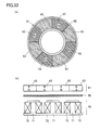
- 34 (a) and 34 (b) are diagrams showing a modification of the fifth embodiment.
- the rotor 61 is provided with a plurality of permanent magnets 63 and a plurality of permanent magnets 67.
- the number of permanent magnets 67 is the same as the number of permanent magnets 63.
- the permanent magnet 67 is magnetized in the circumferential direction (rotation direction of the rotor 61).
- the plurality of permanent magnets 63 and the plurality of permanent magnets 67 are alternately arranged one by one at equal angular intervals along the same circle in a Halbach array structure.
- the permanent magnets 63 with the north pole facing the partition wall 60 and the permanent magnets 63 with the south pole facing the partition wall 60 are alternately arranged along the same circle with gaps at equal angular intervals.
- the N pole of each permanent magnet 67 is arranged toward the permanent magnet 63 with the N pole facing the partition 60 side, and the S pole of each permanent magnet 67 is arranged toward the permanent magnet 63 with the S pole facing the partition 60 side. Is done.
- the shapes of the plurality of permanent magnets 63 are the same, and the shapes of the plurality of permanent magnets 67 are the same.
- the shape of the permanent magnet 63 and the shape of the permanent magnet 67 may be the same or different.
- the attractive force between the permanent magnet 63 and the magnetic body 71 can be suppressed, and the magnetic flux resulting from the torque can be increased, so that the permanent magnet can be most miniaturized (see FIG. 30). That is, the rotor 61 can be most lightened and the energy efficiency can be increased even when the motor gap is wide.
- the magnetic flux causing the attractive force and torque of the permanent magnet 63 and the magnetic body 71 is adjusted by the ratio of the area of the surface of the permanent magnet 63 facing the partition wall 60 and the area of the surface of the permanent magnet 67 facing the partition wall 60. can do.
- the area ratio of the permanent magnet 67 to the permanent magnet 63 is set in a range of 1/2 or more and 2 or less, the rotor 61 is suppressed while reducing the attractive force between the permanent magnet 63 and the magnetic body 71.
- the rotational torque of can be increased. Therefore, the area ratio of the permanent magnet 67 to the permanent magnet 63 is optimally in the range of 1/2 or more and 2 or less.
- the magnetic poles are often composed of only the permanent magnets 63.
- the stator 70 and the rotor regardless of the radial gap type or the axial gap type. Since the gap between 61 becomes large, there is a problem that high torque and high efficiency are difficult.
- the degree of freedom in design is low due to dimensional restrictions and the like, and it is easily affected by local magnetic saturation, and it is difficult to achieve high efficiency.
- the field magnetic flux of the permanent magnet 63 can be efficiently passed through the stator 70 even when the gap between the stator 70 and the rotor 61 is large. Therefore, the motor torque can be increased without increasing the mass of the rotor 61 and without increasing the negative rigidity value in the axial direction with respect to a wide motor gap. Therefore, the rotor 61 can be rotated at high speed, and the rotor 61 can be smoothly rotated and started.
Landscapes
- Engineering & Computer Science (AREA)
- Health & Medical Sciences (AREA)
- Heart & Thoracic Surgery (AREA)
- Mechanical Engineering (AREA)
- Cardiology (AREA)
- General Health & Medical Sciences (AREA)
- Veterinary Medicine (AREA)
- Hematology (AREA)
- Life Sciences & Earth Sciences (AREA)
- Animal Behavior & Ethology (AREA)
- Anesthesiology (AREA)
- Public Health (AREA)
- Biomedical Technology (AREA)
- General Engineering & Computer Science (AREA)
- Physics & Mathematics (AREA)
- Electromagnetism (AREA)
- Fluid Mechanics (AREA)
- Pulmonology (AREA)
- Structures Of Non-Positive Displacement Pumps (AREA)
- External Artificial Organs (AREA)
Priority Applications (1)
| Application Number | Priority Date | Filing Date | Title |
|---|---|---|---|
| US14/372,998 US9366261B2 (en) | 2012-01-18 | 2013-01-09 | Centrifugal pump device |
Applications Claiming Priority (2)
| Application Number | Priority Date | Filing Date | Title |
|---|---|---|---|
| JP2012007845A JP6083929B2 (ja) | 2012-01-18 | 2012-01-18 | 遠心式ポンプ装置 |
| JP2012-007845 | 2012-01-18 |
Publications (1)
| Publication Number | Publication Date |
|---|---|
| WO2013108681A1 true WO2013108681A1 (ja) | 2013-07-25 |
Family
ID=48799108
Family Applications (1)
| Application Number | Title | Priority Date | Filing Date |
|---|---|---|---|
| PCT/JP2013/050187 Ceased WO2013108681A1 (ja) | 2012-01-18 | 2013-01-09 | 遠心式ポンプ装置 |
Country Status (3)
| Country | Link |
|---|---|
| US (1) | US9366261B2 (enExample) |
| JP (1) | JP6083929B2 (enExample) |
| WO (1) | WO2013108681A1 (enExample) |
Cited By (1)
| Publication number | Priority date | Publication date | Assignee | Title |
|---|---|---|---|---|
| WO2016158162A1 (ja) * | 2015-03-30 | 2016-10-06 | Ntn株式会社 | 遠心式ポンプ装置 |
Families Citing this family (19)
| Publication number | Priority date | Publication date | Assignee | Title |
|---|---|---|---|---|
| JP6506579B2 (ja) * | 2015-03-20 | 2019-04-24 | Ntn株式会社 | 回転駆動装置または回転駆動装置を備える遠心式ポンプ装置 |
| JP6577754B2 (ja) * | 2015-05-26 | 2019-09-18 | 日本電産サンキョー株式会社 | 磁気カップリング機構およびこれを備えたポンプ装置 |
| US20170016449A1 (en) * | 2015-07-14 | 2017-01-19 | Hamilton Sundstrand Corporation | Axial-flux induction motor pump |
| ES3026736T3 (en) | 2015-08-04 | 2025-06-12 | Abiomed Europe Gmbh | Blood pump with self-flushing bearing |
| PL3173108T3 (pl) | 2015-11-30 | 2018-12-31 | Fundacja Rozwoju Kardiochirurgii Im. Prof. Zbigniewa Religi | Wirnik z kanałami krytymi dla odśrodkowej wszczepialnej pompy wspomagania serca |
| KR101697148B1 (ko) * | 2016-03-04 | 2017-01-17 | 황광선 | 원심 흡입식 하이브리드 베인 유체기계 |
| US10161908B2 (en) * | 2016-03-24 | 2018-12-25 | Infineon Technologies Ag | Apparatus for determining a characteristic of a fluid having a device configured to measure a hydrodynamic pressure of the fluid |
| CN105641763B (zh) * | 2016-04-12 | 2017-12-01 | 上海理工大学 | 分离型电磁耦合血泵系统 |
| US11324942B2 (en) * | 2016-06-28 | 2022-05-10 | Albert Rather, Jay K. Brama, Md, Gurjap Singh | Medical devices including rotary valve |
| JP7414529B2 (ja) | 2017-06-07 | 2024-01-16 | シファメド・ホールディングス・エルエルシー | 血管内流体移動デバイス、システム、および使用方法 |
| EP3710076B1 (en) | 2017-11-13 | 2023-12-27 | Shifamed Holdings, LLC | Intravascular fluid movement devices, systems, and methods of use |
| EP4085965A1 (en) | 2018-02-01 | 2022-11-09 | Shifamed Holdings, LLC | Intravascular blood pumps and methods of use and manufacture |
| WO2020028537A1 (en) | 2018-07-31 | 2020-02-06 | Shifamed Holdings, Llc | Intravascaular blood pumps and methods of use |
| US12220570B2 (en) | 2018-10-05 | 2025-02-11 | Shifamed Holdings, Llc | Intravascular blood pumps and methods of use |
| EP3754204B1 (de) * | 2019-06-17 | 2022-03-16 | Levitronix GmbH | Lüfter |
| WO2021011473A1 (en) | 2019-07-12 | 2021-01-21 | Shifamed Holdings, Llc | Intravascular blood pumps and methods of manufacture and use |
| WO2021062260A1 (en) | 2019-09-25 | 2021-04-01 | Shifamed Holdings, Llc | Catheter blood pumps and collapsible blood conduits |
| GB2588823A (en) * | 2019-11-11 | 2021-05-12 | Epropelled Ltd | Electrical machine |
| US12409310B2 (en) | 2019-12-11 | 2025-09-09 | Shifamed Holdings, Llc | Descending aorta and vena cava blood pumps |
Citations (3)
| Publication number | Priority date | Publication date | Assignee | Title |
|---|---|---|---|---|
| JP2001329988A (ja) * | 2000-05-19 | 2001-11-30 | Ntn Corp | 液体ポンプ装置 |
| JP2007089972A (ja) * | 2005-09-30 | 2007-04-12 | Terumo Corp | 遠心式血液ポンプ装置 |
| WO2011013483A1 (ja) * | 2009-07-29 | 2011-02-03 | Ntn株式会社 | 回転駆動装置およびそれを用いた遠心式ポンプ装置 |
Family Cites Families (254)
| Publication number | Priority date | Publication date | Assignee | Title |
|---|---|---|---|---|
| US1093868A (en) | 1912-03-11 | 1914-04-21 | Henry W Jacobs | Means for forming couplings or joints. |
| US3960468A (en) | 1946-07-16 | 1976-06-01 | The United States Of America As Represented By The United States Energy Research And Development Administration | Fluid lubricated bearing assembly |
| US2684035A (en) | 1947-10-02 | 1954-07-20 | Philip G Kemp | Fluid pump |
| US3510229A (en) | 1968-07-23 | 1970-05-05 | Maytag Co | One-way pump |
| US3932069A (en) | 1974-12-19 | 1976-01-13 | Ford Motor Company | Variable reluctance motor pump |
| LU77252A1 (enExample) | 1976-05-06 | 1977-08-22 | ||
| FR2451480A1 (fr) | 1979-03-16 | 1980-10-10 | Belenger Jacques | Pompe centrifuge medicale |
| JPH0247496Y2 (enExample) | 1980-05-21 | 1990-12-13 | ||
| US4382199A (en) | 1980-11-06 | 1983-05-03 | Nu-Tech Industries, Inc. | Hydrodynamic bearing system for a brushless DC motor |
| US4688998A (en) | 1981-03-18 | 1987-08-25 | Olsen Don B | Magnetically suspended and rotated impellor pump apparatus and method |
| US5078741A (en) | 1986-10-12 | 1992-01-07 | Life Extenders Corporation | Magnetically suspended and rotated rotor |
| DE3214397C2 (de) | 1982-04-20 | 1984-07-26 | Karl Dr. 6301 Pohlheim Aigner | Perfusions-Doppellumenkatheter |
| US4549860A (en) | 1983-04-04 | 1985-10-29 | Yakich Sam S | Blood pump improvements |
| US4806080A (en) | 1983-07-06 | 1989-02-21 | Ebara Corporation | Pump with shaftless impeller |
| US4686982A (en) | 1985-06-19 | 1987-08-18 | John Nash | Spiral wire bearing for rotating wire drive catheter |
| US4769006A (en) | 1985-05-13 | 1988-09-06 | Kos Medical Technologies, Ltd. | Hydrodynamically propelled pacing catheter |
| US4790843A (en) | 1986-06-16 | 1988-12-13 | Baxter Travenol Laboratories, Inc. | Prosthetic heart valve assembly |
| US4753221A (en) | 1986-10-22 | 1988-06-28 | Intravascular Surgical Instruments, Inc. | Blood pumping catheter and method of use |
| US4902272A (en) | 1987-06-17 | 1990-02-20 | Abiomed Cardiovascular, Inc. | Intra-arterial cardiac support system |
| US4930997A (en) | 1987-08-19 | 1990-06-05 | Bennett Alan N | Portable medical suction device |
| US4846152A (en) | 1987-11-24 | 1989-07-11 | Nimbus Medical, Inc. | Single-stage axial flow blood pump |
| US4817586A (en) | 1987-11-24 | 1989-04-04 | Nimbus Medical, Inc. | Percutaneous bloom pump with mixed-flow output |
| US4895557A (en) | 1987-12-07 | 1990-01-23 | Nimbus Medical, Inc. | Drive mechanism for powering intravascular blood pumps |
| US5092879A (en) | 1988-02-17 | 1992-03-03 | Jarvik Robert K | Intraventricular artificial hearts and methods of their surgical implantation and use |
| US4906229A (en) | 1988-05-03 | 1990-03-06 | Nimbus Medical, Inc. | High-frequency transvalvular axisymmetric blood pump |
| FR2632686B1 (enExample) | 1988-06-14 | 1993-07-16 | Thomson Brandt Armements | |
| US4908012A (en) | 1988-08-08 | 1990-03-13 | Nimbus Medical, Inc. | Chronic ventricular assist system |
| US4964864A (en) | 1988-09-27 | 1990-10-23 | American Biomed, Inc. | Heart assist pump |
| US4919647A (en) | 1988-10-13 | 1990-04-24 | Kensey Nash Corporation | Aortically located blood pumping catheter and method of use |
| US4957504A (en) | 1988-12-02 | 1990-09-18 | Chardack William M | Implantable blood pump |
| US4969865A (en) | 1989-01-09 | 1990-11-13 | American Biomed, Inc. | Helifoil pump |
| US4944722A (en) | 1989-02-23 | 1990-07-31 | Nimbus Medical, Inc. | Percutaneous axial flow blood pump |
| US4995857A (en) | 1989-04-07 | 1991-02-26 | Arnold John R | Left ventricular assist device and method for temporary and permanent procedures |
| US5324177A (en) | 1989-05-08 | 1994-06-28 | The Cleveland Clinic Foundation | Sealless rotodynamic pump with radially offset rotor |
| US4985014A (en) | 1989-07-11 | 1991-01-15 | Orejola Wilmo C | Ventricular venting loop |
| US5147186A (en) | 1989-08-04 | 1992-09-15 | Bio Medicus, Inc. | Blood pump drive system |
| JPH03111697A (ja) | 1989-09-22 | 1991-05-13 | Jidosha Denki Kogyo Co Ltd | 小型遠心ポンプ |
| US5112202A (en) | 1990-01-31 | 1992-05-12 | Ntn Corporation | Turbo pump with magnetically supported impeller |
| JP3025295B2 (ja) | 1990-10-11 | 2000-03-27 | エヌティエヌ株式会社 | ターボ形ポンプ |
| US5145333A (en) | 1990-03-01 | 1992-09-08 | The Cleveland Clinic Foundation | Fluid motor driven blood pump |
| FR2659396B1 (fr) | 1990-03-07 | 1992-05-15 | Cit Alcatel | Pompe a vide pour vide moleculaire propre. |
| JPH0636821B2 (ja) | 1990-03-08 | 1994-05-18 | 健二 山崎 | 体内埋設形の補助人工心臓 |
| US5092844A (en) | 1990-04-10 | 1992-03-03 | Mayo Foundation For Medical Education And Research | Intracatheter perfusion pump apparatus and method |
| US5211546A (en) | 1990-05-29 | 1993-05-18 | Nu-Tech Industries, Inc. | Axial flow blood pump with hydrodynamically suspended rotor |
| DE4020120A1 (de) | 1990-06-25 | 1991-01-31 | Klaus Prof Dr Ing Affeld | Medizinische vorrichtung zur erzeugung eines alternierenden volumenstroms fuer den antrieb von implantierbaren blutpumpen |
| CA2022019C (en) | 1990-07-26 | 1992-12-29 | Michael Black | Catheter |
| JP2989233B2 (ja) | 1990-07-31 | 1999-12-13 | エヌティエヌ株式会社 | ターボ形ポンプ |
| US5195877A (en) | 1990-10-05 | 1993-03-23 | Kletschka Harold D | Fluid pump with magnetically levitated impeller |
| US5190528A (en) | 1990-10-19 | 1993-03-02 | Boston University | Percutaneous transseptal left atrial cannulation system |
| DE4111713A1 (de) | 1991-04-10 | 1993-01-14 | Magnet Motor Gmbh | Fluidpumpe |
| US5106372A (en) | 1991-05-03 | 1992-04-21 | Sherwood Medical Company | Single use syringe |
| JPH0521197U (ja) | 1991-05-17 | 1993-03-19 | 株式会社荏原製作所 | キヤンドモータポンプ |
| US5584803A (en) | 1991-07-16 | 1996-12-17 | Heartport, Inc. | System for cardiac procedures |
| US5290236A (en) | 1991-09-25 | 1994-03-01 | Baxter International Inc. | Low priming volume centrifugal blood pump |
| US5449342A (en) | 1991-09-30 | 1995-09-12 | Nippon Zeon Co., Ltd. | Apparatus for assisting blood circulation |
| US5360445A (en) | 1991-11-06 | 1994-11-01 | International Business Machines Corporation | Blood pump actuator |
| US5201679A (en) | 1991-12-13 | 1993-04-13 | Attwood Corporation | Marine propeller with breakaway hub |
| US5306295A (en) | 1992-04-30 | 1994-04-26 | University Of Utah Research Foundation | Electrohydraulic heart with septum mounted pump |
| US5300112A (en) | 1992-07-14 | 1994-04-05 | Aai Corporation | Articulated heart pump |
| US5354331A (en) | 1992-07-15 | 1994-10-11 | Schachar Ronald A | Treatment of presbyopia and other eye disorders |
| JP2564843Y2 (ja) | 1992-07-29 | 1998-03-11 | 日本ビクター株式会社 | すべりスラスト軸受け構造 |
| US5290227A (en) | 1992-08-06 | 1994-03-01 | Pasque Michael K | Method of implanting blood pump in ascending aorta or main pulmonary artery |
| US5312341A (en) | 1992-08-14 | 1994-05-17 | Wayne State University | Retaining apparatus and procedure for transseptal catheterization |
| SE501215C2 (sv) | 1992-09-02 | 1994-12-12 | Oeyvind Reitan | Kateterpump |
| US5376114A (en) | 1992-10-30 | 1994-12-27 | Jarvik; Robert | Cannula pumps for temporary cardiac support and methods of their application and use |
| FR2698560B1 (fr) | 1992-11-30 | 1995-02-03 | Virbac Laboratoires | Principes actifs pulvérulents stabilisés, compositions les contenant, leur procédé d'obtention et leurs applications. |
| JP2583924Y2 (ja) | 1992-12-25 | 1998-10-27 | エヌティエヌ株式会社 | クリーンポンプ |
| US5332374A (en) | 1992-12-30 | 1994-07-26 | Ralph Kricker | Axially coupled flat magnetic pump |
| US5643226A (en) | 1993-02-24 | 1997-07-01 | Minnesota Mining And Manufacturing | Low velocity aortic cannula |
| DE4321260C1 (de) | 1993-06-25 | 1995-03-09 | Westphal Dieter Dipl Ing Dipl | Blutpumpe als Zentrifugalpumpe |
| JP3898754B2 (ja) | 1993-07-01 | 2007-03-28 | ボストン サイエンティフィック リミテッド | 像形成、電位検出型及び切除カテーテル |
| JPH0714220U (ja) | 1993-08-18 | 1995-03-10 | アスモ株式会社 | 液中軸受 |
| US5527159A (en) | 1993-11-10 | 1996-06-18 | The United States Of America As Represented By The Administrator Of The National Aeronautics And Space Administration | Rotary blood pump |
| JPH0742869U (ja) | 1993-12-28 | 1995-08-11 | 象印マホービン株式会社 | 遠心ポンプ |
| EP0741584A1 (en) | 1994-02-01 | 1996-11-13 | Howmedica Inc. | Coated femoral stem prosthesis |
| US5597377A (en) | 1994-05-06 | 1997-01-28 | Trustees Of Boston University | Coronary sinus reperfusion catheter |
| US5607407A (en) | 1994-05-09 | 1997-03-04 | Tolkoff; Marc J. | Catheter assembly |
| US5507629A (en) | 1994-06-17 | 1996-04-16 | Jarvik; Robert | Artificial hearts with permanent magnet bearings |
| US5504978A (en) | 1994-07-15 | 1996-04-09 | Meyer, Iii; Harold A. | Locking clamp assembly |
| US5569111A (en) | 1994-10-11 | 1996-10-29 | The United States Of America As Represented By The Secretary Of The Navy | Permanent magnet torque/force transfer apparatus |
| US5613935A (en) | 1994-12-16 | 1997-03-25 | Jarvik; Robert | High reliability cardiac assist system |
| US5725357A (en) | 1995-04-03 | 1998-03-10 | Ntn Corporation | Magnetically suspended type pump |
| EP0819330B1 (de) | 1995-04-03 | 2001-06-06 | Levitronix LLC | Rotationsmaschine mit elektromagnetischem drehantrieb |
| US5707218A (en) | 1995-04-19 | 1998-01-13 | Nimbus, Inc. | Implantable electric axial-flow blood pump with blood cooled bearing |
| US5938412A (en) | 1995-06-01 | 1999-08-17 | Advanced Bionics, Inc. | Blood pump having rotor with internal bore for fluid flow |
| US6206659B1 (en) | 1995-06-01 | 2001-03-27 | Advanced Bionics, Inc. | Magnetically driven rotor for blood pump |
| US5924848A (en) | 1995-06-01 | 1999-07-20 | Advanced Bionics, Inc. | Blood pump having radial vanes with enclosed magnetic drive components |
| US5793974A (en) | 1995-06-30 | 1998-08-11 | Sun Microsystems, Inc. | Network navigation and viewing system for network management system |
| US6007479A (en) | 1996-07-08 | 1999-12-28 | H.D.S. Systems Ltd. | Heart assist system and method |
| US5575630A (en) | 1995-08-08 | 1996-11-19 | Kyocera Corporation | Blood pump having magnetic attraction |
| US5924975A (en) | 1995-08-30 | 1999-07-20 | International Business Machines Corporation | Linear pump |
| DE19535781C2 (de) | 1995-09-26 | 1999-11-11 | Fraunhofer Ges Forschung | Vorrichtung zur aktiven Strömungsunterstützung von Körperflüssigkeiten |
| JPH09122228A (ja) | 1995-10-27 | 1997-05-13 | Terumo Corp | 遠心ポンプ駆動制御装置および体外循環血液回路用送血装置 |
| US5947703A (en) | 1996-01-31 | 1999-09-07 | Ntn Corporation | Centrifugal blood pump assembly |
| US5695471A (en) | 1996-02-20 | 1997-12-09 | Kriton Medical, Inc. | Sealless rotary blood pump with passive magnetic radial bearings and blood immersed axial bearings |
| US5840070A (en) | 1996-02-20 | 1998-11-24 | Kriton Medical, Inc. | Sealless rotary blood pump |
| DE19613564C1 (de) | 1996-04-04 | 1998-01-08 | Guenter Prof Dr Rau | Intravasale Blutpumpe |
| US5868703A (en) | 1996-04-10 | 1999-02-09 | Endoscopic Technologies, Inc. | Multichannel catheter |
| US5738649A (en) | 1996-04-16 | 1998-04-14 | Cardeon Corporation | Peripheral entry biventricular catheter system for providing access to the heart for cardiopulmonary surgery or for prolonged circulatory support of the heart |
| US5611679A (en) | 1996-04-22 | 1997-03-18 | Eastman Kodak Company | Corrosion-resistant pump |
| US5814011A (en) | 1996-04-25 | 1998-09-29 | Medtronic, Inc. | Active intravascular lung |
| US5746709A (en) | 1996-04-25 | 1998-05-05 | Medtronic, Inc. | Intravascular pump and bypass assembly and method for using the same |
| US6074180A (en) | 1996-05-03 | 2000-06-13 | Medquest Products, Inc. | Hybrid magnetically suspended and rotated centrifugal pumping apparatus and method |
| US6254359B1 (en) | 1996-05-10 | 2001-07-03 | The United States Of America As Represented By The Administrator Of The National Aeronautics And Space Administration | Method for providing a jewel bearing for supporting a pump rotor shaft |
| JPH09313600A (ja) | 1996-05-28 | 1997-12-09 | Terumo Corp | 遠心式液体ポンプ装置 |
| US6244835B1 (en) | 1996-06-26 | 2001-06-12 | James F. Antaki | Blood pump having a magnetically suspended rotor |
| DE19629614A1 (de) | 1996-07-23 | 1998-01-29 | Cardiotools Herzchirurgietechn | Linksherzassistpumpe |
| US5755783A (en) | 1996-07-29 | 1998-05-26 | Stobie; Robert | Suture rings for rotatable artificial heart valves |
| CA2237203C (en) | 1996-09-10 | 2007-09-18 | Sulzer Electronics Ag | Rotary pump and method for operation thereof |
| CA2265754C (en) | 1996-09-13 | 2006-10-24 | Medtronic, Inc. | Prosthetic heart valve with suturing member having non-uniform radial width |
| US5851174A (en) | 1996-09-17 | 1998-12-22 | Robert Jarvik | Cardiac support device |
| JP4104088B2 (ja) | 1996-10-04 | 2008-06-18 | ユナイテッド ステイツ サージカル コーポレイション | 循環器支援システム |
| US6071093A (en) | 1996-10-18 | 2000-06-06 | Abiomed, Inc. | Bearingless blood pump and electronic drive system |
| US5888242A (en) | 1996-11-01 | 1999-03-30 | Nimbus, Inc. | Speed control system for implanted blood pumps |
| US5776111A (en) | 1996-11-07 | 1998-07-07 | Medical Components, Inc. | Multiple catheter assembly |
| US5807311A (en) | 1996-11-29 | 1998-09-15 | Palestrant; Aubrey M. | Dialysis catheter having rigid and collapsible lumens and related method |
| US6123460A (en) | 1997-02-28 | 2000-09-26 | Sumitomo Electric Industries, Ltd. | Hydrodynamic gas bearing structure and optical deflection scanner comprising the same |
| US5890883A (en) | 1997-03-19 | 1999-04-06 | The Cleveland Clinic Foundation | Rotodynamic pump with non-circular hydrodynamic bearing journal |
| US5964694A (en) | 1997-04-02 | 1999-10-12 | Guidant Corporation | Method and apparatus for cardiac blood flow assistance |
| AUPO902797A0 (en) | 1997-09-05 | 1997-10-02 | Cortronix Pty Ltd | A rotary blood pump with hydrodynamically suspended impeller |
| JPH10331841A (ja) | 1997-05-27 | 1998-12-15 | Sony Corp | 動圧流体軸受装置及び動圧流体軸受装置の製造方法 |
| US6532964B2 (en) | 1997-07-11 | 2003-03-18 | A-Med Systems, Inc. | Pulmonary and circulatory blood flow support devices and methods for heart surgery procedures |
| US6709418B1 (en) | 1997-07-11 | 2004-03-23 | A-Med Systems, Inc. | Apparatus and methods for entering cavities of the body |
| US6123725A (en) | 1997-07-11 | 2000-09-26 | A-Med Systems, Inc. | Single port cardiac support apparatus |
| EP0928613A4 (en) | 1997-07-25 | 2001-01-17 | Sun Medical Technology Res Cor | PORTABLE DRIVE SYSTEM FOR AN ARTIFICIAL HEART |
| EP0899855B1 (de) | 1997-08-25 | 2006-03-08 | Levitronix LLC | Magnetgelagerte Rotationsanordnung |
| DE59712162D1 (de) | 1997-09-04 | 2005-02-17 | Levitronix Llc Waltham | Zentrifugalpumpe |
| JP3919896B2 (ja) | 1997-09-05 | 2007-05-30 | テルモ株式会社 | 遠心式液体ポンプ装置 |
| US6610004B2 (en) | 1997-10-09 | 2003-08-26 | Orqis Medical Corporation | Implantable heart assist system and method of applying same |
| UA56262C2 (uk) | 1997-10-09 | 2003-05-15 | Орквіс Медікел Корпорейшн | Імплантовувана система підтримки серця |
| US5928131A (en) | 1997-11-26 | 1999-07-27 | Vascor, Inc. | Magnetically suspended fluid pump and control system |
| US6422990B1 (en) | 1997-11-26 | 2002-07-23 | Vascor, Inc. | Blood pump flow rate control method and apparatus utilizing multiple sensors |
| US6293901B1 (en) | 1997-11-26 | 2001-09-25 | Vascor, Inc. | Magnetically suspended fluid pump and control system |
| JPH11244377A (ja) | 1998-03-03 | 1999-09-14 | Terumo Corp | 遠心式血液ポンプ装置 |
| DE29804046U1 (de) | 1998-03-07 | 1998-04-30 | Günther, Rolf W., Prof. Dr.med., 52074 Aachen | Perkutan implantierbare selbstentfaltbare Axialpumpe zur temporären Herzunterstützung |
| US6176822B1 (en) | 1998-03-31 | 2001-01-23 | Impella Cardiotechnik Gmbh | Intracardiac blood pump |
| US6086527A (en) | 1998-04-02 | 2000-07-11 | Scimed Life Systems, Inc. | System for treating congestive heart failure |
| US6508777B1 (en) | 1998-05-08 | 2003-01-21 | Cardeon Corporation | Circulatory support system and method of use for isolated segmental perfusion |
| DE19821307C1 (de) | 1998-05-13 | 1999-10-21 | Impella Cardiotech Gmbh | Intrakardiale Blutpumpe |
| US6042347A (en) | 1998-07-27 | 2000-03-28 | Scholl; Frank G. | Pedia-cadio pump |
| US6135943A (en) | 1998-08-07 | 2000-10-24 | Cardiac Assist Technologies, Inc. | Non-invasive flow indicator for a rotary blood pump |
| WO2000018448A2 (en) | 1998-09-30 | 2000-04-06 | A-Med Systems, Inc. | Method and apparatus for preventing air embolisms |
| US6149683A (en) | 1998-10-05 | 2000-11-21 | Kriton Medical, Inc. | Power system for an implantable heart pump |
| US6264635B1 (en) | 1998-12-03 | 2001-07-24 | Kriton Medical, Inc. | Active magnetic bearing system for blood pump |
| AU2485100A (en) | 1998-12-23 | 2000-07-12 | A-Med Systems, Inc. | Left and right side heart support |
| US6158984A (en) | 1998-12-28 | 2000-12-12 | Kriton Medical, Inc. | Rotary blood pump with ceramic members |
| US7329236B2 (en) | 1999-01-11 | 2008-02-12 | Flowmedica, Inc. | Intra-aortic renal drug delivery catheter |
| US6749598B1 (en) | 1999-01-11 | 2004-06-15 | Flowmedica, Inc. | Apparatus and methods for treating congestive heart disease |
| US6123659A (en) | 1999-01-26 | 2000-09-26 | Nimbus Inc. | Blood pump with profiled outflow region |
| US6245007B1 (en) | 1999-01-28 | 2001-06-12 | Terumo Cardiovascular Systems Corporation | Blood pump |
| US6319231B1 (en) | 1999-02-12 | 2001-11-20 | Abiomed, Inc. | Medical connector |
| EP1034808A1 (en) | 1999-03-09 | 2000-09-13 | Paul Frederik Gründeman | A device for transventricular mechanical circulatory support |
| US6295877B1 (en) | 1999-03-30 | 2001-10-02 | A-Med Systems, Inc. | Pressure sensing cannula |
| AUPP995999A0 (en) | 1999-04-23 | 1999-05-20 | University Of Technology, Sydney | Non-contact estimation and control system |
| US6234772B1 (en) | 1999-04-28 | 2001-05-22 | Kriton Medical, Inc. | Rotary blood pump |
| JP4043644B2 (ja) | 1999-05-06 | 2008-02-06 | 日本電産株式会社 | 動圧軸受装置の製造方法 |
| US6146325A (en) | 1999-06-03 | 2000-11-14 | Arrow International, Inc. | Ventricular assist device |
| EP1063753B1 (de) | 1999-06-22 | 2009-07-22 | Levitronix LLC | Elektrischer Drehantrieb mit einem magnetisch gelagerten Rotor |
| US6190304B1 (en) | 1999-07-13 | 2001-02-20 | University Of North Texas Health Science Center At Fort Worth | Enhanced intra-aortic balloon assist device |
| US6247892B1 (en) | 1999-07-26 | 2001-06-19 | Impsa International Inc. | Continuous flow rotary pump |
| US7022100B1 (en) | 1999-09-03 | 2006-04-04 | A-Med Systems, Inc. | Guidable intravascular blood pump and related methods |
| US6227820B1 (en) | 1999-10-05 | 2001-05-08 | Robert Jarvik | Axial force null position magnetic bearing and rotary blood pumps which use them |
| DE29921352U1 (de) | 1999-12-04 | 2001-04-12 | Impella Cardiotechnik AG, 52074 Aachen | Intravasale Blutpumpe |
| DE19963662C2 (de) | 1999-12-29 | 2003-10-16 | Guido Brohlburg | Direkt beschiefertes Aufsparren Dämmsystem für Hausdächer |
| US6439845B1 (en) | 2000-03-23 | 2002-08-27 | Kidney Replacement Services, P.C. | Blood pump |
| JP5214836B2 (ja) | 2000-03-27 | 2013-06-19 | ザ クリーブランド クリニック ファウンデーション | ターボ形血液ポンプ用長期性能制御システム |
| JP2001309628A (ja) | 2000-04-19 | 2001-11-02 | Unisia Jecs Corp | モータポンプ |
| US6547530B2 (en) | 2000-05-19 | 2003-04-15 | Ntn Corporation | Fluid pump apparatus |
| US6458163B1 (en) | 2000-07-11 | 2002-10-01 | Prosthetic Design, Inc. | Coupling-socket adapter assembly for a prosthetic limb |
| AU2002217770A1 (en) | 2000-11-16 | 2002-05-27 | Geoff Briggs | Automatic suture fixation apparatus and method |
| DE10058669B4 (de) | 2000-11-25 | 2004-05-06 | Impella Cardiotechnik Ag | Mikromotor |
| DE10059714C1 (de) | 2000-12-01 | 2002-05-08 | Impella Cardiotech Ag | Intravasale Pumpe |
| DE10060275A1 (de) | 2000-12-05 | 2002-06-13 | Impella Cardiotech Ag | Verfahren zum Kalibrieren eines Drucksensors oder eines Flussensors an einer Rotationspumpe |
| US20020095210A1 (en) | 2001-01-16 | 2002-07-18 | Finnegan Michael T. | Heart pump graft connector and system |
| DE10108810A1 (de) | 2001-02-16 | 2002-08-29 | Berlin Heart Ag | Vorrichtung zur axialen Förderung von Flüssigkeiten |
| US6547519B2 (en) | 2001-04-13 | 2003-04-15 | Hewlett Packard Development Company, L.P. | Blower impeller apparatus with pivotable blades |
| US6517315B2 (en) | 2001-05-29 | 2003-02-11 | Hewlett-Packard Company | Enhanced performance fan with the use of winglets |
| US20020188167A1 (en) | 2001-06-06 | 2002-12-12 | Anthony Viole | Multilumen catheter for minimizing limb ischemia |
| US20030023302A1 (en) | 2001-07-26 | 2003-01-30 | Riyad Moe | Sewing cuff assembly for heart valves |
| US6623420B2 (en) | 2001-08-16 | 2003-09-23 | Apex Medical, Inc. | Physiological heart pump control |
| US6808371B2 (en) | 2001-09-25 | 2004-10-26 | Matsushita Electric Industrial Co., Ltd. | Ultra-thin pump and cooling system including the pump |
| US6942672B2 (en) | 2001-10-23 | 2005-09-13 | Vascor, Inc. | Method and apparatus for attaching a conduit to the heart or a blood vessel |
| US6692318B2 (en) | 2001-10-26 | 2004-02-17 | The Penn State Research Foundation | Mixed flow pump |
| JP4060570B2 (ja) | 2001-11-02 | 2008-03-12 | テルモ株式会社 | 遠心式血液ポンプ |
| CA2471484A1 (en) | 2002-01-08 | 2003-07-17 | Micromed Technology, Inc. | Method and system for detecting ventricular collapse |
| US6991595B2 (en) | 2002-04-19 | 2006-01-31 | Thoratec Corporation | Adaptive speed control for blood pump |
| US20040024285A1 (en) | 2002-06-21 | 2004-02-05 | Helmut Muckter | Blood pump with impeller |
| US6732501B2 (en) | 2002-06-26 | 2004-05-11 | Heartware, Inc. | Ventricular connector |
| US7241257B1 (en) | 2002-06-28 | 2007-07-10 | Abbott Cardiovascular Systems, Inc. | Devices and methods to perform minimally invasive surgeries |
| US6949188B2 (en) | 2002-07-15 | 2005-09-27 | Geyer's Manufacturing & Design, Inc. | Filter assembly having improved sealing features |
| US7578843B2 (en) | 2002-07-16 | 2009-08-25 | Medtronic, Inc. | Heart valve prosthesis |
| US7959674B2 (en) | 2002-07-16 | 2011-06-14 | Medtronic, Inc. | Suture locking assembly and method of use |
| US6949066B2 (en) | 2002-08-21 | 2005-09-27 | World Heart Corporation | Rotary blood pump diagnostics and cardiac output controller |
| US6817836B2 (en) | 2002-09-10 | 2004-11-16 | Miwatec Incorporated | Methods and apparatus for controlling a continuous flow rotary blood pump |
| JP4186593B2 (ja) | 2002-11-13 | 2008-11-26 | 松下電工株式会社 | Dcブラシレスモータ及びそれを備えたdcポンプ |
| US6860713B2 (en) | 2002-11-27 | 2005-03-01 | Nidec Corporation | Fan with collapsible blades, redundant fan system, and related method |
| EP1430919A1 (en) | 2002-12-17 | 2004-06-23 | Terumo Kabushiki Kaisha | Centrifugal blood pump apparatus |
| JP4456857B2 (ja) | 2002-12-17 | 2010-04-28 | テルモ株式会社 | 遠心式血液ポンプ装置 |
| US7048681B2 (en) | 2003-03-28 | 2006-05-23 | Terumo Corporation | Method and apparatus for adjusting a length of the inflow conduit on a ventricular assist device |
| JP2004332566A (ja) | 2003-04-30 | 2004-11-25 | Yamada Seisakusho Co Ltd | マグネットポンプ |
| TWI297282B (en) | 2003-05-22 | 2008-06-01 | Ind Tech Res Inst | High performance purification process and device for high specific resistance liquid crystal |
| US7128538B2 (en) | 2003-07-07 | 2006-10-31 | Terumo Corporation | Centrifugal fluid pump apparatus |
| US7416525B2 (en) | 2003-09-18 | 2008-08-26 | Myrakelle, Llc | Rotary blood pump |
| ATE406685T1 (de) | 2003-10-03 | 2008-09-15 | Foster Miller Inc | Drehpumpe mit elektromagnetischem lcr-lager |
| JP4767488B2 (ja) | 2003-10-23 | 2011-09-07 | Ntn株式会社 | 磁気浮上型ポンプ |
| DE102004019721A1 (de) | 2004-03-18 | 2005-10-06 | Medos Medizintechnik Ag | Pumpe |
| EP1598087B1 (en) | 2004-03-24 | 2010-02-03 | Terumo Kabushiki Kaisha | blood pump with hydrodynamic bearing |
| JP4340178B2 (ja) | 2004-03-24 | 2009-10-07 | テルモ株式会社 | 遠心式血液ポンプ装置 |
| JP4233475B2 (ja) | 2004-03-25 | 2009-03-04 | テルモ株式会社 | 遠心式血液ポンプ装置 |
| US7160243B2 (en) | 2004-03-25 | 2007-01-09 | Terumo Corporation | Method and system for controlling blood pump flow |
| JP4340183B2 (ja) | 2004-03-31 | 2009-10-07 | テルモ株式会社 | 遠心式血液ポンプ装置 |
| US7172551B2 (en) | 2004-04-12 | 2007-02-06 | Scimed Life Systems, Inc. | Cyclical pressure coronary assist pump |
| JP2006002937A (ja) | 2004-05-20 | 2006-01-05 | Minebea Co Ltd | 流体動圧軸受装置およびその製造方法、スピンドルモータ、および記録ディスク駆動装置 |
| KR100600758B1 (ko) | 2004-09-15 | 2006-07-19 | 엘지전자 주식회사 | 모터의 스테이터 및 그 제조방법 |
| US7393181B2 (en) | 2004-09-17 | 2008-07-01 | The Penn State Research Foundation | Expandable impeller pump |
| US7699586B2 (en) | 2004-12-03 | 2010-04-20 | Heartware, Inc. | Wide blade, axial flow pump |
| US8419609B2 (en) | 2005-10-05 | 2013-04-16 | Heartware Inc. | Impeller for a rotary ventricular assist device |
| JP4759261B2 (ja) | 2004-12-16 | 2011-08-31 | テルモ株式会社 | 遠心式血液ポンプ装置 |
| DE102005017546A1 (de) | 2005-04-16 | 2006-10-19 | Impella Cardiosystems Gmbh | Verfahren zur Steuerung einer Blutpumpe |
| JP2007002885A (ja) | 2005-06-22 | 2007-01-11 | Aisin Takaoka Ltd | 差動装置 |
| JP2007043621A (ja) | 2005-08-05 | 2007-02-15 | Matsushita Electric Ind Co Ltd | アンテナ装置およびアンテナ装置の製造方法 |
| JP4472612B2 (ja) | 2005-09-30 | 2010-06-02 | テルモ株式会社 | 遠心式血液ポンプ装置 |
| US9744279B2 (en) | 2005-12-08 | 2017-08-29 | Heartware, Inc. | Implant connector |
| EP3954901A1 (en) | 2006-01-13 | 2022-02-16 | HeartWare, Inc. | Rotary blood pump |
| US8672611B2 (en) | 2006-01-13 | 2014-03-18 | Heartware, Inc. | Stabilizing drive for contactless rotary blood pump impeller |
| JP5068951B2 (ja) | 2006-02-08 | 2012-11-07 | 本田技研工業株式会社 | モータ用ロータの製造方法および製造装置 |
| US20070213690A1 (en) | 2006-03-08 | 2007-09-13 | Nickolas Phillips | Blood conduit connector |
| JP2007247489A (ja) | 2006-03-15 | 2007-09-27 | Asmo Co Ltd | 電動ポンプ |
| CN101448535B (zh) | 2006-03-23 | 2011-10-19 | 宾州研究基金会 | 带有可膨胀叶轮泵的心脏辅助装置 |
| WO2007115222A2 (en) | 2006-03-31 | 2007-10-11 | Orqis Medical Corporation | Rotary blood pump |
| US7850594B2 (en) | 2006-05-09 | 2010-12-14 | Thoratec Corporation | Pulsatile control system for a rotary blood pump |
| JP4898319B2 (ja) | 2006-06-23 | 2012-03-14 | テルモ株式会社 | 血液ポンプ装置 |
| JP2008104278A (ja) | 2006-10-18 | 2008-05-01 | Honda Motor Co Ltd | モータ |
| JP4787726B2 (ja) | 2006-11-28 | 2011-10-05 | テルモ株式会社 | センサレス磁気軸受型血液ポンプ装置 |
| JP4959424B2 (ja) | 2007-05-31 | 2012-06-20 | 勇 青谷 | ポンプ装置 |
| JP4707696B2 (ja) | 2007-06-26 | 2011-06-22 | 本田技研工業株式会社 | アキシャルギャップ型モータ |
| DE102007043575A1 (de) | 2007-09-13 | 2009-03-26 | Minebea Co., Ltd. | Fluiddynamische Lagerstruktur und fluiddynamisches Lager |
| WO2009057667A1 (en) | 2007-10-29 | 2009-05-07 | Semiconductor Energy Laboratory Co., Ltd. | Formation method of single crystal semiconductor layer, formation method of crystalline semiconductor layer, formation method of polycrystalline layer, and method for manufacturing semiconductor device |
| US7942805B2 (en) | 2007-12-27 | 2011-05-17 | Heartware, Inc. | VAD connector plug |
| JP5171953B2 (ja) | 2008-06-23 | 2013-03-27 | テルモ株式会社 | 血液ポンプ装置 |
| WO2010067682A1 (ja) | 2008-12-08 | 2010-06-17 | Ntn株式会社 | 遠心式ポンプ装置 |
| JP5347171B2 (ja) | 2008-12-11 | 2013-11-20 | ソラテック コーポレーション | 遠心式ポンプ装置 |
| JP5378010B2 (ja) | 2009-03-05 | 2013-12-25 | ソラテック コーポレーション | 遠心式ポンプ装置 |
| US8770945B2 (en) | 2009-03-06 | 2014-07-08 | Thoratec Corporation | Centrifugal pump apparatus |
| US9682180B2 (en) | 2009-11-15 | 2017-06-20 | Thoratec Corporation | Attachment system, device and method |
| US20110118829A1 (en) | 2009-11-15 | 2011-05-19 | Thoratec Corporation | Attachment device and method |
| JP5443197B2 (ja) | 2010-02-16 | 2014-03-19 | ソラテック コーポレーション | 遠心式ポンプ装置 |
| WO2011118325A1 (ja) | 2010-03-26 | 2011-09-29 | テルモ株式会社 | 遠心式血液ポンプ装置 |
| JP5681403B2 (ja) | 2010-07-12 | 2015-03-11 | ソーラテック コーポレイション | 遠心式ポンプ装置 |
| JP5577506B2 (ja) | 2010-09-14 | 2014-08-27 | ソーラテック コーポレイション | 遠心式ポンプ装置 |
| EP3020426B1 (en) | 2010-09-24 | 2017-12-27 | Tc1 Llc | Generating artificial pulse |
| JP2012200285A (ja) | 2011-03-23 | 2012-10-22 | Toshiba Corp | 画像処理装置、x線ct装置、及び画像処理方法 |
| EP2693609B1 (en) | 2011-03-28 | 2017-05-03 | Thoratec Corporation | Rotation and drive device and centrifugal pump device using same |
| US8579790B2 (en) | 2012-01-05 | 2013-11-12 | Thoratec Corporation | Apical ring for ventricular assist device |
-
2012
- 2012-01-18 JP JP2012007845A patent/JP6083929B2/ja active Active
-
2013
- 2013-01-09 WO PCT/JP2013/050187 patent/WO2013108681A1/ja not_active Ceased
- 2013-01-09 US US14/372,998 patent/US9366261B2/en not_active Expired - Fee Related
Patent Citations (3)
| Publication number | Priority date | Publication date | Assignee | Title |
|---|---|---|---|---|
| JP2001329988A (ja) * | 2000-05-19 | 2001-11-30 | Ntn Corp | 液体ポンプ装置 |
| JP2007089972A (ja) * | 2005-09-30 | 2007-04-12 | Terumo Corp | 遠心式血液ポンプ装置 |
| WO2011013483A1 (ja) * | 2009-07-29 | 2011-02-03 | Ntn株式会社 | 回転駆動装置およびそれを用いた遠心式ポンプ装置 |
Cited By (2)
| Publication number | Priority date | Publication date | Assignee | Title |
|---|---|---|---|---|
| WO2016158162A1 (ja) * | 2015-03-30 | 2016-10-06 | Ntn株式会社 | 遠心式ポンプ装置 |
| JP2016188592A (ja) * | 2015-03-30 | 2016-11-04 | Ntn株式会社 | 遠心式ポンプ装置 |
Also Published As
| Publication number | Publication date |
|---|---|
| JP2013147969A (ja) | 2013-08-01 |
| US20150010415A1 (en) | 2015-01-08 |
| JP6083929B2 (ja) | 2017-02-22 |
| US9366261B2 (en) | 2016-06-14 |
Similar Documents
| Publication | Publication Date | Title |
|---|---|---|
| JP6083929B2 (ja) | 遠心式ポンプ装置 | |
| JP5681403B2 (ja) | 遠心式ポンプ装置 | |
| JP5656835B2 (ja) | 回転駆動装置およびそれを用いた遠心式ポンプ装置 | |
| JP5378010B2 (ja) | 遠心式ポンプ装置 | |
| JP5443197B2 (ja) | 遠心式ポンプ装置 | |
| JP5577506B2 (ja) | 遠心式ポンプ装置 | |
| JP5577503B2 (ja) | 遠心式ポンプ装置 | |
| JP5347171B2 (ja) | 遠心式ポンプ装置 | |
| JP5378012B2 (ja) | 遠心式ポンプ装置 | |
| WO2010067682A1 (ja) | 遠心式ポンプ装置 | |
| WO2010101107A1 (ja) | 遠心式ポンプ装置 | |
| JP5693812B2 (ja) | 遠心式ポンプ装置 | |
| JP5378060B2 (ja) | 遠心式ポンプ装置 | |
| JP2012013043A (ja) | 回転駆動装置およびそれを用いた遠心式ポンプ装置 | |
| JP2010131303A (ja) | 遠心式ポンプ装置 |
Legal Events
| Date | Code | Title | Description |
|---|---|---|---|
| 121 | Ep: the epo has been informed by wipo that ep was designated in this application |
Ref document number: 13738407 Country of ref document: EP Kind code of ref document: A1 |
|
| NENP | Non-entry into the national phase |
Ref country code: DE |
|
| WWE | Wipo information: entry into national phase |
Ref document number: 14372998 Country of ref document: US |
|
| 122 | Ep: pct application non-entry in european phase |
Ref document number: 13738407 Country of ref document: EP Kind code of ref document: A1 |