WO2013108460A1 - 血圧測定装置、および、血圧測定装置の制御方法 - Google Patents
血圧測定装置、および、血圧測定装置の制御方法 Download PDFInfo
- Publication number
- WO2013108460A1 WO2013108460A1 PCT/JP2012/077710 JP2012077710W WO2013108460A1 WO 2013108460 A1 WO2013108460 A1 WO 2013108460A1 JP 2012077710 W JP2012077710 W JP 2012077710W WO 2013108460 A1 WO2013108460 A1 WO 2013108460A1
- Authority
- WO
- WIPO (PCT)
- Prior art keywords
- control
- voltage
- amplitude
- pressure
- blood pressure
- Prior art date
Links
Images


Classifications
-
- A—HUMAN NECESSITIES
- A61—MEDICAL OR VETERINARY SCIENCE; HYGIENE
- A61B—DIAGNOSIS; SURGERY; IDENTIFICATION
- A61B5/00—Measuring for diagnostic purposes; Identification of persons
- A61B5/02—Detecting, measuring or recording pulse, heart rate, blood pressure or blood flow; Combined pulse/heart-rate/blood pressure determination; Evaluating a cardiovascular condition not otherwise provided for, e.g. using combinations of techniques provided for in this group with electrocardiography or electroauscultation; Heart catheters for measuring blood pressure
- A61B5/021—Measuring pressure in heart or blood vessels
- A61B5/022—Measuring pressure in heart or blood vessels by applying pressure to close blood vessels, e.g. against the skin; Ophthalmodynamometers
- A61B5/0225—Measuring pressure in heart or blood vessels by applying pressure to close blood vessels, e.g. against the skin; Ophthalmodynamometers the pressure being controlled by electric signals, e.g. derived from Korotkoff sounds
-
- A—HUMAN NECESSITIES
- A61—MEDICAL OR VETERINARY SCIENCE; HYGIENE
- A61B—DIAGNOSIS; SURGERY; IDENTIFICATION
- A61B5/00—Measuring for diagnostic purposes; Identification of persons
- A61B5/02—Detecting, measuring or recording pulse, heart rate, blood pressure or blood flow; Combined pulse/heart-rate/blood pressure determination; Evaluating a cardiovascular condition not otherwise provided for, e.g. using combinations of techniques provided for in this group with electrocardiography or electroauscultation; Heart catheters for measuring blood pressure
- A61B5/021—Measuring pressure in heart or blood vessels
- A61B5/02141—Details of apparatus construction, e.g. pump units or housings therefor, cuff pressurising systems, arrangements of fluid conduits or circuits
-
- A—HUMAN NECESSITIES
- A61—MEDICAL OR VETERINARY SCIENCE; HYGIENE
- A61B—DIAGNOSIS; SURGERY; IDENTIFICATION
- A61B5/00—Measuring for diagnostic purposes; Identification of persons
- A61B5/02—Detecting, measuring or recording pulse, heart rate, blood pressure or blood flow; Combined pulse/heart-rate/blood pressure determination; Evaluating a cardiovascular condition not otherwise provided for, e.g. using combinations of techniques provided for in this group with electrocardiography or electroauscultation; Heart catheters for measuring blood pressure
- A61B5/021—Measuring pressure in heart or blood vessels
- A61B5/022—Measuring pressure in heart or blood vessels by applying pressure to close blood vessels, e.g. against the skin; Ophthalmodynamometers
- A61B5/02225—Measuring pressure in heart or blood vessels by applying pressure to close blood vessels, e.g. against the skin; Ophthalmodynamometers using the oscillometric method
-
- A—HUMAN NECESSITIES
- A61—MEDICAL OR VETERINARY SCIENCE; HYGIENE
- A61B—DIAGNOSIS; SURGERY; IDENTIFICATION
- A61B5/00—Measuring for diagnostic purposes; Identification of persons
- A61B5/02—Detecting, measuring or recording pulse, heart rate, blood pressure or blood flow; Combined pulse/heart-rate/blood pressure determination; Evaluating a cardiovascular condition not otherwise provided for, e.g. using combinations of techniques provided for in this group with electrocardiography or electroauscultation; Heart catheters for measuring blood pressure
- A61B5/021—Measuring pressure in heart or blood vessels
- A61B5/022—Measuring pressure in heart or blood vessels by applying pressure to close blood vessels, e.g. against the skin; Ophthalmodynamometers
- A61B5/02233—Occluders specially adapted therefor
Definitions
- the present invention relates to a blood pressure measurement device and a control method for the blood pressure measurement device, and more particularly, to a blood pressure measurement device suitable for measuring blood pressure in a cuff pressurizing process, and a control method for the blood pressure measurement device.
- An electronic blood pressure monitor using an oscillometric method is used as a general electronic blood pressure monitor.
- an arm band with an air bag is evenly wrapped around a part of a living body, and the air bag is pressurized and depressurized with air, so that the volume change of the compressed arterial blood vessel is changed to air.
- the blood pressure is calculated by capturing the change in the amplitude of the bag pressure (cuff pressure).
- cuff pressure the pressurization speed of the cuff internal pressure. For example, it is necessary to pressurize at a constant speed.
- Patent Document 1 proposes a piezoelectric micropump that is driven using a piezoelectric element, and can be applied to an electronic blood pressure monitor.
- Patent Document 2 proposes Japanese Patent Application Laid-Open No. 2010-255447
- Patent Document 3 proposes Japanese Patent Application Laid-Open No. 2010-162487
- the driving frequency is determined by the material of the piezoelectric element and the diaphragm. It has been proposed to control near the drive frequency.
- pump output control is performed by PWM (Pulse Width Modulation) control, but piezoelectric pump output control is generally driven at a driving frequency and output control is performed by voltage control. .
- PWM Pulse Width Modulation
- the present invention has been made to solve the above-described problems, and one of its purposes is to generate noise when pressurization control is performed using a piezoelectric pump in a pressurization process for blood pressure measurement. It is to provide a blood pressure measuring device and a method for controlling the blood pressure measuring device that can suppress the blood pressure and improve the blood pressure measurement accuracy by reducing the influence of pulsation and highly accurate pressurization control.
- a blood pressure measurement device includes: a cuff that compresses an artery of a measurement site with the pressure of an internal fluid when the blood pressure measurement device is attached to the blood pressure measurement site; A pressure pump that pressurizes the pressure inside the cuff, a pressure reducing unit that reduces the pressure inside the cuff, a pressure detecting unit that detects the cuff pressure that is the pressure inside the cuff, and a control unit.
- the control unit determines a control amplitude and a control frequency of a voltage applied to the piezoelectric pump, and an applied voltage control unit controls the voltage of the control amplitude and the control frequency determined by the determination unit to be applied to the piezoelectric pump.
- a blood pressure measurement unit that calculates a blood pressure value based on the cuff pressure detected by the pressure detection unit in the pressurization process of increasing the cuff pressure by the piezoelectric pump.
- the applied voltage control unit is capable of controlling the amplitude of the voltage at a predetermined stage.
- the applied voltage control unit is configured so that the output of the piezoelectric pump is approximately equivalent to the case where the voltage of the control amplitude determined by the determining unit is applied.
- a voltage having an amplitude of at least one stage value and at least one stage value below is applied in a predetermined order.
- the applied voltage control unit alternately applies voltages having two amplitudes.
- the two values are a predetermined level, an upper value, and a predetermined level and a lower value, respectively, with respect to the control amplitude determined by the determination unit.
- the control unit further alternates the two values of voltage based on the control amplitude and the two values determined by the determination unit so that the output of the piezoelectric pump is substantially equivalent to the case where the voltage of the control amplitude is applied.
- An application rate determining unit that determines a time rate to be applied to is included.
- the applied voltage control unit applies voltages having two amplitudes at a time ratio determined by the application ratio determining unit.
- the applied voltage control unit applies the voltage so that the difference between the two values is minimized.
- the applied voltage control unit alternately applies voltages having two amplitudes determined by the determination unit at the same time ratio.
- the control unit further controls the upper and lower values of the control amplitude so that the output of the piezoelectric pump is substantially equivalent to the case where the voltage of the control amplitude is applied based on the control amplitude determined by the determination unit.
- an applied voltage determining unit that determines two values of the values of the steps.
- the applied voltage control unit alternately applies voltages having two amplitudes determined by the applied voltage determining unit.
- the applied voltage determination unit determines the value so that the difference between the two values is minimized.
- the determination unit determines an optimum frequency as the control frequency for the value of the amplitude of the voltage applied by the applied voltage control unit.
- a method for controlling a blood pressure measurement device includes a cuff that compresses an artery of a measurement site with the pressure of an internal fluid when the blood pressure measurement device is attached to the blood pressure measurement site, and a pressure inside the cuff.
- a method for controlling a blood pressure measurement apparatus comprising: a piezoelectric pump for pressurization; a decompression unit that decompresses pressure inside the cuff; a pressure detection unit that detects cuff pressure that is the pressure inside the cuff; and a control unit.
- the control method includes a step in which a control unit determines a control amplitude and a control frequency of a voltage to be applied to the piezoelectric pump, a step of controlling to apply a voltage of the determined control amplitude and control frequency to the piezoelectric pump, and a piezoelectric Calculating a blood pressure value based on the cuff pressure detected by the pressure detection unit in the pressurizing process in which the cuff pressure is increased by the pump.
- the controlling step is capable of controlling the amplitude of the voltage in a predetermined step, and is substantially equivalent to the case where the voltage having the determined control amplitude is applied, and the value of at least one step above and below the control amplitude. Applying a voltage having an amplitude of at least one stage value in a predetermined order.
- the control amplitude and the control frequency of the voltage applied to the piezoelectric pump are determined, the voltage of the determined control amplitude and control frequency is controlled to be applied to the piezoelectric pump, and the cuff pressure is applied by the piezoelectric pump.
- a blood pressure value is calculated based on the cuff pressure detected by the pressure detector in the pressurizing process.
- the amplitude of the voltage can be controlled in a predetermined stage, and the value of at least one stage above the control amplitude and the value so as to be substantially equivalent to the case where the voltage of the determined control amplitude is applied, and A voltage with an amplitude of at least one lower level value is applied in a predetermined order.
- the piezoelectric pump can be controlled to be substantially equivalent to the case where the target voltage is applied by amplitude modulating the applied voltage.
- it is possible to suppress the generation of noise at the frequency of amplitude modulation as compared with the case of control by amplitude modulation.
- pulsation occurs in the pressurized cuff pressure, but according to the present invention, the influence of pulsation can be reduced.
- it is possible to perform pressurization control with high accuracy as in the case of control by amplitude modulation.
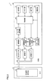
- FIG. 1 is a perspective view showing an appearance of a sphygmomanometer 1 according to the embodiment of the present invention.
- sphygmomanometer 1 in this embodiment includes a main body 10, a cuff 40, and an air tube 50.
- the main body 10 has a box-shaped housing, and has a display unit 21 and an operation unit 23 on an upper surface thereof.
- the main body 10 is used by being placed on a placement surface such as a table at the time of measurement.
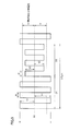
- the cuff 40 mainly has a belt-like and bag-like outer cover 41 and a compression air bag 42 as a compression fluid bag contained in the outer cover 41 and has a substantially annular shape as a whole. is doing.
- the cuff 40 is used by being wound around the upper arm of the subject at the time of measurement.
- the air pipe 50 connects the main body 10 and the cuff 40 which are configured separately.
- FIG. 2 is a block diagram showing an outline of the configuration of the sphygmomanometer 1 in this embodiment.
- main body 10 includes control unit 20, memory unit 22, power supply unit 24, piezoelectric pump 31, exhaust valve 32, pressure sensor, in addition to display unit 21 and operation unit 23 described above. 33, a DC-DC booster circuit 61, a voltage control circuit 62, a drive control circuit 63, an amplifier 71, and an A / D converter 72.
- the piezoelectric pump 31 and the exhaust valve 32 correspond to a pressure increasing / decreasing mechanism for increasing / decreasing the internal pressure of the compression air bladder 42.
- the compression air bag 42 is for compressing the upper arm in the mounted state, and has a lumen inside thereof.
- the compression air bag 42 is connected to each of the piezoelectric pump 31, the exhaust valve 32, and the pressure sensor 33 described above via the air pipe 50 described above. Thereby, the compression air bag 42 is pressurized and expanded by driving the piezoelectric pump 31, and the internal pressure is maintained or reduced by controlling the driving of the exhaust valve 32 as a discharge valve. To do.
- the control unit 20 is configured by, for example, a CPU (Central Processing Unit), and is a means for controlling the entire sphygmomanometer 1.
- a CPU Central Processing Unit
- the display unit 21 is composed of, for example, an LCD (Liquid Crystal Display) and is a means for displaying measurement results and the like.
- LCD Liquid Crystal Display
- the memory unit 22 is composed of, for example, a ROM (Read-Only Memory) or a RAM (Random-Access Memory), and stores a program for causing the control unit 20 or the like to execute a processing procedure for blood pressure value measurement or measurement. It is a means for storing results and the like.
- the operation unit 23 is a means for accepting an operation by a subject or the like and inputting a command from the outside to the control unit 20 or the power supply unit 24.
- the power supply unit 24 is a means for supplying electric power to each unit of the sphygmomanometer 1 such as the control unit 20 and the piezoelectric pump 31, and is a battery in this embodiment.
- the present invention is not limited to this, and the power source unit 24 may receive power from an external power source such as a commercial power source.
- the control unit 20 inputs control signals for driving the piezoelectric pump 31 and the exhaust valve 32 to the voltage control circuit 62 and the drive control circuit 63, respectively, and displays blood pressure values as measurement results on the display unit 21 and the memory unit 22.
- type in The control unit 20 includes a blood pressure information acquisition unit (not shown) that acquires the blood pressure value of the subject based on the pressure value detected from the pressure sensor 33 via the amplifier 71 and the A / D converter 72.
- the blood pressure value acquired by the blood pressure information measuring unit is input to the display unit 21 and the memory unit 22 described above as a measurement result.
- the sphygmomanometer 1 may further include an output unit that outputs a blood pressure value as a measurement result to an external device such as a PC (Personal Computer) or a printer.
- an output unit for example, a serial communication line, a writing device for various recording media, or the like can be used.
- the DC-DC booster circuit 61 is a circuit that boosts the voltage of the battery serving as the power supply unit 24 to a voltage suitable for driving the piezoelectric pump 31.
- the voltage control circuit 62 controls the voltage supplied to the piezoelectric pump 31 based on the voltage value indicated by the control signal input from the control unit 20.
- the drive control circuit 63 controls the piezoelectric pump 31 and the exhaust valve 32 based on the control signal input from the control unit 20. Specifically, the drive control circuit 63 controls the frequency of the current supplied to the piezoelectric pump 31 based on the control frequency indicated by the control signal input from the control unit 20. The drive control circuit 63 controls the opening / closing operation of the exhaust valve 32 based on the control signal input from the control unit 20.
- the piezoelectric pump 31 is for pressurizing the internal pressure (hereinafter also referred to as “cuff pressure”) of the compression air bag 42 by supplying air to the inner cavity of the compression air bag 42, and the operation thereof is described above.
- the drive control circuit 63 is controlled.
- the piezoelectric pump 31 discharges air with a predetermined flow rate by applying an alternating current with a predetermined drive frequency f0 and a predetermined amplitude V0.
- the alternating current may be a sinusoidal alternating current or a rectangular wave alternating current.
- the value of the peak-to-peak potential difference Vp-p may be used.
- the amplitude is half of the value of Vp-p. In the case of Vp-p, for example, the voltage value changes with a value from ⁇ Vp-p / 2 to Vp-p / 2.
- the exhaust valve 32 is for maintaining the internal pressure of the compression air bag 42 or opening the lumen of the compression air bag 42 to the outside to reduce the cuff pressure. It is controlled by the control circuit 63.
- the pressure sensor 33 detects the internal pressure of the compression air bladder 42 and inputs an output signal corresponding to the pressure to the amplifier 71.
- the amplifier 71 amplifies the level of the signal input from the pressure sensor 33.
- the A / D converter 72 converts the signal amplified by the amplifier 71 into a digital signal, and inputs the generated digital signal to the control unit 20.
- FIG. 3 is a graph showing the flow rate required for constant speed pressurization.
- the piezoelectric pump 31 when the piezoelectric pump 31 is controlled at a constant voltage, when the potential difference between the peaks of the voltage is 15 Vp-p, when the cuff pressure is about 0 mmHg, the flow rate discharged from the piezoelectric pump 31 is about At 50 ml / min at 50 mmHg, it is about 25 ml / min, and at 110 mmHg, it is about 0 ml / min.
- the discharge flow rate of the piezoelectric pump 31 is about 100 ml / min, about 70 ml / min as the cuff pressure increases to about 0 mmHg, 50 mmHg, 100 mmHg, 150 mmHg, 170 mmHg. It decreases to min, about 30 ml / min, about 10 ml / min, and about 0 ml / min.
- the discharge flow rate of the piezoelectric pump 31 is increased as the cuff pressure increases. ,Decrease.
- the cuff pressure is 30 mmHg to 250 mmHg when the wrist circumference, which is the attachment site of the cuff 40, is the minimum length that can be handled by the cuff 40. To about 35 ml / min from about 30 ml / min.
- the wrist circumference is the maximum length that can be handled by the cuff 40
- the flow rate required for the isobaric pressurization is about 145 ml / min.
- the cuff pressure is 100 mmHg, it is about 80 ml / min, when it is 150 mmHg, it is about 75 ml / min, and when it is 250 mmHg, it is about 75 ml / min.
- the flow rate with respect to the cuff pressure is controlled within the constant pressure pressurization control range hatched by the diagonal lines in the graph of FIG. As a result, the cuff 40 can be pressurized with an equal pressure.
- the flow rate is controlled to change as described above according to the increase in the cuff pressure, and when the cuff 40 is pressurized at a constant pressure, the peak between the voltages applied to the piezoelectric pump 31 is reduced.
- the potential difference needs to be reduced from about 26 Vp-p to about 23 Vp-p until the cuff pressure reaches about 60 mmHg and then increased to control it to about 37 Vp-p when the cuff pressure reaches 250 mmHg. .
- the peak-to-peak voltage range is approximately 12 Vp-p to 40 Vp-p, that is, the amplitude range is 6 V to 20 V. Therefore, it is necessary to control the voltage of the piezoelectric pump 31. Moreover, since it is digital control, it is necessary to improve the resolution of the control voltage in order to improve the system for controlling the pressurization speed. However, this requires an expensive control circuit, which leads to an increase in the manufacturing cost of the sphygmomanometer 1.
- FIG. 4 is a graph showing changes in cuff pressure when the control voltage of the piezoelectric pump 31 is modulated by AM (Amplitude Modulation). Referring to FIG. 4, it is conceivable to AM modulate the control voltage in order to improve the resolution of the control voltage.
- FIG. 5 is a diagram showing the concept of voltage control of the piezoelectric pump 31 of the present invention.
- blood pressure monitor 1 in this embodiment digitally controls the voltage applied to piezoelectric pump 31, so that the controllable voltage amplitude value is stepwise. For example, if the control step is 1V and the target voltage amplitude V0 is 20.3V, for example, 20V or 21V can be applied to the piezoelectric pump 31, but 20.3V is applied to the piezoelectric pump. I can't.
- the period of the ratio D1 in a certain period 1 / f_am is driven with the drive voltage having the amplitude V1 and the optimum frequency f1 with respect to the drive voltage having the amplitude V1, and the period of the ratio D2 is set.
- the piezoelectric pump 31 is controlled so as to discharge a flow rate substantially equivalent to the case of driving with the target voltage having the amplitude V0 by driving at the driving voltage having the amplitude V2 and the optimum frequency f2 with respect to the driving voltage having the amplitude V2.
- f_am is the same frequency as the AM modulation (amplitude modulation) frequency described with reference to FIG. 4, for example, a value of about 30 Hz to about 200 Hz, but the blood pressure pulse wave component is 30 Hz or less. Since it is included in the frequency, it is necessary that the frequency be higher than 30 Hz. However, other frequencies may be used as long as the frequency is lower than the driving frequency of the piezoelectric pump (for example, a value around 20 kHz).
- f_am If the value of f_am increases, the control responsiveness improves, but the processing load of the control unit 20 increases, so the value of f_am is determined based on the processing speed of the control unit 20.
- V1 and V2 are as small as possible, noise due to pulsation can be suppressed or the volume of noise can be reduced.
- V0 20.3V
- V1 21V
- V2 20V
- DUTY ratio D1 0.3
- the difference between V1 and V2 is preferably as small as possible, so the latter is preferable.
- FIG. 6 is a graph for explaining a control result when the voltage of the piezoelectric pump 31 is controlled according to the embodiment of the present invention.
- a graph indicated by a one-dot chain line and a graph indicated by a broken line indicate changes in the discharge flow rate of the piezoelectric pump 31 in the pressurizing process when the piezoelectric pump 31 is driven at 20 V and 21 V, respectively. Show.
- the graph shown by the solid line shows the discharge flow rate of the piezoelectric pump 31 in the pressurizing process when the piezoelectric pump 31 is driven by switching between 20 V and 21 V with a DUTY ratio of 50% when the target voltage is 20.5 V. Shows changes. Thus, it is shown that when the target voltage is 20.5 V and the control is switched between 20 V and 21 V, the discharge flow rate is exactly the middle between the case of driving at 20 V and the case of driving at 21 V.
- FIG. 7 is a flowchart showing the flow of blood pressure measurement processing executed by the sphygmomanometer 1 according to the first embodiment.
- control unit 20 is necessary for the cuff 40 winding state (wrist circumference, tight winding or loose winding), current cuff pressure, and constant speed pressurization.
- the amplitude V of the target voltage of the piezoelectric pump 31 is determined based on data as shown in the graph shown in FIG.
- step S112 the control unit 20 drives to discharge a flow rate similar to the target voltage V0 within the period 1 / f_am of the predetermined AM modulation frequency f_am according to the method described in FIG. V1 and V2 and DUTY ratios D1 and D2 when the voltages V1 and V2 are switched and controlled are calculated.
- step S113 the control unit 20 determines whether or not V1 and V2 calculated in step S112 satisfy a relationship of
- the control unit 20 determines that it is not equal to or lower than the limit (when determining NO in step S113), the control unit 20 returns the process to be executed to the process of step S112.
- step S114 the control unit 20 displays the characteristics of the piezoelectric pump 31 stored in the memory unit 22 in advance. Based on the data, optimum frequencies f1, f2 adapted to V1, V2 calculated in step S112 are determined.
- the optimum frequency is a frequency at which the maximum flow rate can be discharged, but may be a frequency that maximizes the pump efficiency.
- step S121 the voltage value is supplied to the voltage control circuit 62 so as to drive the piezoelectric pump 31 for the time D1 / f_am with the drive voltage V1 calculated in step S112 and the drive frequency f1 calculated in step S114.
- a signal indicating the drive frequency is transmitted to the drive control circuit 63.
- step S122 the voltage value is supplied to the voltage control circuit 62 so as to drive the piezoelectric pump 31 for the time D2 / f_am with the drive voltage V2 calculated in step S112 and the drive frequency f2 calculated in step S114.
- a signal indicating the drive frequency is transmitted to the drive control circuit 63.
- step S123 the control unit 20 is detected by the pressure sensor 33, and based on the change in the cuff pressure indicated by the signal input to the control unit 20 via the amplifier 71 and the A / D converter 72, The blood pressure value is calculated by a conventional method.
- step S124 the control unit 20 determines whether the blood pressure measurement is completed. If it is determined that the blood pressure measurement has not been completed (NO in step S124), the control unit 20 returns the process to be executed to the process in step S111.
- step S125 the control unit 20 stops the driving of the piezoelectric pump 31 and the voltage control circuit 62 and the drive control circuit 63. To control.
- step S126 the control unit 20 controls the display unit 21 to display the blood pressure measurement result. After step S126, the control unit 20 ends the blood pressure measurement process.
- FIG. 8 is a flowchart showing the flow of blood pressure measurement processing executed by the sphygmomanometer 1 according to the second embodiment.
- step S131 is the same as the process of step S111 described with reference to FIG. 7 of the first embodiment, and therefore, repeated description will not be repeated.
- step S133 the control unit 20 discharges the same flow rate as the target voltage V0 within the period 1 / f_am of the predetermined AM modulation frequency f_am in accordance with the method described in FIG. DUTY ratios D1 and D2 are calculated when the drive voltages V1 and V2 determined in the above are switched and controlled.
- step S134 the control unit 20 determines optimum frequencies f1 and f2 adapted to V1 and V2 calculated in step S132 based on the characteristic data of the piezoelectric pump 31 stored in advance in the memory unit 22.
- step S121 to step S126 Since the processing from step S121 to step S126 is the same as the processing described in FIG. 7, overlapping description will not be repeated.
- the sphygmomanometer 1 in this embodiment exhibits the following effects.
- the sphygmomanometer 1 includes a cuff 40 that compresses the artery of the measurement site with the pressure of the internal fluid when attached to the blood pressure measurement site, a piezoelectric pump 31 that pressurizes the internal pressure of the cuff 40, and the cuff
- the control unit 20 determines the control amplitude and control frequency of the voltage applied to the piezoelectric pump 31 as shown in steps S111 to S114 in FIG. 7 and steps S131 to S134 in FIG. As shown in step S121 and step S122 of FIG. 8, control is performed so that the voltages having the determined control amplitudes V1 and V2 and control frequencies f1 and f2 are applied to the piezoelectric pump 31, and is shown in step S123 of FIGS. As described above, the blood pressure value is calculated based on the cuff pressure detected by the pressure sensor 33 in the pressurizing process in which the cuff pressure is increased by the piezoelectric pump 31. Further, as shown in steps S111 and S112 in FIG. 7 and steps S131 to S133 in FIG.
- the control unit 20 controls the amplitude of the voltage at a predetermined stage.
- a voltage having the amplitude of the value V2 is applied in a predetermined order.
- the piezoelectric pump 31 can be controlled so that the discharge flow rate is substantially equivalent to the case where the target voltage is applied by AM modulating the applied voltage.
- it is possible to suppress the generation of noise at the frequency of AM modulation as compared with the case of controlling by AM modulation.
- pulsation occurs in the pressurized cuff pressure, but according to the sphygmomanometer 1 of this embodiment, the influence of pulsation can be reduced.
- high-precision pressurization control can be performed as in the case of control by AM modulation.
- step S121 and step S122 in FIG. 8 the control unit 20 alternately applies voltages having two amplitudes.
- the two values are a predetermined stage ("1" stage in the second embodiment), an upper value V1, and a predetermined stage and a lower value V2 of the determined control amplitude V0.
- step S133 of FIG. 8 the control unit 20 applies the voltage of the control amplitude V0 based on the determined control amplitude V0 and the two values V1 and V2, and the output of the piezoelectric pump 31.
- time ratios D1 and D2 for alternately applying voltages of two values V1 and V2.
- steps S121 and S122 of FIG. 8 the control unit 20 applies voltages having amplitudes of two values V1 and V2 at the determined time ratios D1 and D2.
- control unit 20 applies a voltage so that the difference between the two values V1 and V2 is minimized.
- the control unit 20 performs control so that the output of the piezoelectric pump 31 is substantially equivalent to the case where the voltage of the control amplitude V0 is applied based on the determined control amplitude V0. Two values of the amplitude V0, the upper stage value V1 and the lower stage value V2, are determined.
- steps S121 and S122 of FIG. 7 the control unit 20 alternately applies voltages having amplitudes of the two determined values V1 and V2.
- step S113 of FIG. 7 the control unit 20 determines whether or not the difference between the two values V1 and V2 is equal to or less than a predetermined value Limit. It was re-determined so that the difference between the two values V1 and V2 was less than Limit. Further, the control unit 20 may determine the value so that the difference between the two values is minimized.
- the noise due to pulsation can be suppressed, and the volume of the noise can be reduced.
- control unit 20 determines optimal frequencies f1 and f2 as control frequencies for the amplitude values V1 and V2 of the applied voltage. To do.
- the piezoelectric pump 31 can be optimally controlled at any timing.
- the fluid supplied from the piezoelectric pump 31 to the cuff 40 is air.
- the fluid supplied from the piezoelectric pump 31 to the cuff 40 may be another fluid, for example, a liquid or a gel. Or it is not limited to fluid, Uniform microparticles, such as a microbead, may be sufficient.
- the size of the measurement site is the wrist circumference.
- the measurement site is not limited to this. If the measurement site is different, the measurement site has a different size. For example, when the measurement site is an arm, it is the arm circumference.
- the present invention is not limited to this, and the control parameter update and blood pressure value calculation cycle may be every multiple cycles of DUTY control.
- step S112 in FIG. 7 the voltage amplitudes V1 and V2 may be determined first, and the DUTY ratios D1 and D2 may be calculated accordingly.
- the DUTY ratios D1 and D2 may be determined first, and the voltage amplitudes V1 and V2 may be calculated.
- the present invention is not limited to this, and control may be performed while switching the amplitude of three or more voltages.
- the amplitude of four voltages of 19V, 20V, 21V, and 22V is sequentially switched at a DUTY ratio of 0.25 so that a flow rate equivalent to a target voltage having an amplitude of 20.5V can be discharged. May be.
- the voltage V1 that is one higher than the controllable resolution and the voltage V2 that is one lower than the target voltage V0 are determined. I tried to do it. Thereby, a voltage can be applied so that the difference between V1 and V2 is minimized.
- the invention has been described as the device of the sphygmomanometer 1.
- the present invention is not limited to this, and the invention can be understood as a method for controlling the sphygmomanometer 1.
- the invention can be understood as a control program for the sphygmomanometer 1.
Landscapes
- Health & Medical Sciences (AREA)
- Life Sciences & Earth Sciences (AREA)
- Cardiology (AREA)
- Vascular Medicine (AREA)
- Heart & Thoracic Surgery (AREA)
- Surgery (AREA)
- Biophysics (AREA)
- Pathology (AREA)
- Engineering & Computer Science (AREA)
- Biomedical Technology (AREA)
- Physiology (AREA)
- Medical Informatics (AREA)
- Molecular Biology (AREA)
- Physics & Mathematics (AREA)
- Animal Behavior & Ethology (AREA)
- General Health & Medical Sciences (AREA)
- Public Health (AREA)
- Veterinary Medicine (AREA)
- Ophthalmology & Optometry (AREA)
- Dentistry (AREA)
- Measuring Pulse, Heart Rate, Blood Pressure Or Blood Flow (AREA)
Priority Applications (3)
| Application Number | Priority Date | Filing Date | Title |
|---|---|---|---|
| US14/371,795 US9198584B2 (en) | 2012-01-16 | 2012-10-26 | Blood pressure measurement device and control method for blood pressure measurement device |
| CN201280056197.XA CN103930019B (zh) | 2012-01-16 | 2012-10-26 | 血压测量装置和血压测量装置的控制方法 |
| DE112012005676.0T DE112012005676T5 (de) | 2012-01-16 | 2012-10-26 | Blutdruckmesseinrichtung und Steuerverfahren für die Blutdruckmesseinrichtung |
Applications Claiming Priority (2)
| Application Number | Priority Date | Filing Date | Title |
|---|---|---|---|
| JP2012-006089 | 2012-01-16 | ||
| JP2012006089A JP5884496B2 (ja) | 2012-01-16 | 2012-01-16 | 血圧測定装置、および、血圧測定装置の制御方法 |
Publications (2)
| Publication Number | Publication Date |
|---|---|
| WO2013108460A1 true WO2013108460A1 (ja) | 2013-07-25 |
| WO2013108460A9 WO2013108460A9 (ja) | 2014-05-30 |
Family
ID=48798897
Family Applications (1)
| Application Number | Title | Priority Date | Filing Date |
|---|---|---|---|
| PCT/JP2012/077710 WO2013108460A1 (ja) | 2012-01-16 | 2012-10-26 | 血圧測定装置、および、血圧測定装置の制御方法 |
Country Status (5)
| Country | Link |
|---|---|
| US (1) | US9198584B2 (zh) |
| JP (1) | JP5884496B2 (zh) |
| CN (1) | CN103930019B (zh) |
| DE (1) | DE112012005676T5 (zh) |
| WO (1) | WO2013108460A1 (zh) |
Cited By (1)
| Publication number | Priority date | Publication date | Assignee | Title |
|---|---|---|---|---|
| US10408210B2 (en) * | 2016-02-03 | 2019-09-10 | Microjet Technology Co., Ltd. | Driving circuit for piezoelectric pump and control method thereof |
Families Citing this family (19)
| Publication number | Priority date | Publication date | Assignee | Title |
|---|---|---|---|---|
| US7553295B2 (en) | 2002-06-17 | 2009-06-30 | Iradimed Corporation | Liquid infusion apparatus |
| US8105282B2 (en) | 2007-07-13 | 2012-01-31 | Iradimed Corporation | System and method for communication with an infusion device |
| CN107040164B (zh) * | 2016-02-03 | 2020-05-26 | 研能科技股份有限公司 | 控制方法及驱动电路 |
| TWI604821B (zh) * | 2016-11-11 | 2017-11-11 | Microlife Corp | 具有壓電幫浦的血壓測量裝置及具有壓電幫浦的血壓測量裝置的控制方法 |
| US10874307B2 (en) * | 2017-01-24 | 2020-12-29 | Verily Life Sciences Llc | Digital artery blood pressure monitor |
| US10313963B2 (en) * | 2017-02-27 | 2019-06-04 | Samsung Electronics Co., Ltd. | Methods for selecting radio access technology (RAT) modes in wireless communication devices |
| JP6658958B2 (ja) * | 2017-03-16 | 2020-03-04 | 株式会社村田製作所 | 流体制御装置および血圧計 |
| EP3558169B1 (en) | 2017-04-18 | 2022-01-19 | Edwards Lifesciences Corporation | Heart valve sealing devices and delivery devices therefor |
| CN107126200A (zh) * | 2017-06-23 | 2017-09-05 | 深圳市永盟智能信息系统有限公司 | 血压计系统及检测方法 |
| CN107536605B (zh) * | 2017-09-05 | 2020-05-05 | 广州视源电子科技股份有限公司 | 一种pwm电路占空比调节方法、控制器和血压测量装置 |
| CN107479446A (zh) * | 2017-09-11 | 2017-12-15 | 深圳市景新浩科技有限公司 | 一种新型安全稳定压电泵接入电源控制器 |
| US10874308B2 (en) * | 2017-09-29 | 2020-12-29 | Fitbit, Inc. | Devices and methods for obtaining pulse information from blood pressure measurements |
| US11268506B2 (en) | 2017-12-22 | 2022-03-08 | Iradimed Corporation | Fluid pumps for use in MRI environment |
| CN109938749B (zh) * | 2019-04-03 | 2021-09-14 | 李�浩 | 一种动脉位置检测装置及其使用方法 |
| TWI697200B (zh) * | 2019-04-03 | 2020-06-21 | 研能科技股份有限公司 | 微型壓電泵模組 |
| GB2575945B (en) * | 2019-11-11 | 2023-02-08 | Ttp Ventus Ltd | System for non-invasive blood pressure measurement |
| US20220015652A1 (en) * | 2020-07-14 | 2022-01-20 | Apple Inc. | Integrated Flexible Sensor for Blood Pressure Measurements |
| US11744476B2 (en) | 2020-08-20 | 2023-09-05 | Apple Inc. | Blood pressure measurement using device with piezoelectric sensor |
| JP2022102939A (ja) * | 2020-12-25 | 2022-07-07 | ミネベアミツミ株式会社 | ポンプシステム、流体供給装置およびポンプシステムの駆動制御方法 |
Citations (2)
| Publication number | Priority date | Publication date | Assignee | Title |
|---|---|---|---|---|
| JPH05100630A (ja) * | 1991-10-08 | 1993-04-23 | Semiconductor Energy Lab Co Ltd | 電気光学装置の表示方法 |
| JPH05146414A (ja) * | 1991-11-27 | 1993-06-15 | Sharp Corp | 血圧測定装置 |
Family Cites Families (17)
| Publication number | Priority date | Publication date | Assignee | Title |
|---|---|---|---|---|
| JPH05164414A (ja) * | 1991-12-13 | 1993-06-29 | Mitsubishi Electric Corp | 冷凍サイクル装置 |
| US6428134B1 (en) * | 1998-06-12 | 2002-08-06 | Eastman Kodak Company | Printer and method adapted to reduce variability in ejected ink droplet volume |
| JP3925858B2 (ja) * | 2002-11-08 | 2007-06-06 | 日本精密測器株式会社 | 非観血式血圧計 |
| US7287965B2 (en) * | 2004-04-02 | 2007-10-30 | Adaptiv Energy Llc | Piezoelectric devices and methods and circuits for driving same |
| JP4607547B2 (ja) * | 2004-11-02 | 2011-01-05 | 日本精密測器株式会社 | 電子血圧計の圧力制御方法及び脈波弁別方法 |
| CN100488446C (zh) * | 2005-07-14 | 2009-05-20 | 优盛医学科技股份有限公司 | 智能型加压控制装置 |
| JP4047898B1 (ja) * | 2006-09-29 | 2008-02-13 | シチズンホールディングス株式会社 | 電子血圧計 |
| JP4213188B2 (ja) * | 2007-02-06 | 2009-01-21 | シチズンホールディングス株式会社 | 電子血圧計 |
| JP4957480B2 (ja) | 2007-09-20 | 2012-06-20 | 株式会社村田製作所 | 圧電マイクロポンプ |
| JP5146996B2 (ja) * | 2007-10-25 | 2013-02-20 | テルモ株式会社 | 血圧測定装置およびその制御方法 |
| BRPI0907547B8 (pt) * | 2008-02-28 | 2021-07-27 | Koninklijke Philips Electronics Nv | sistema de ressonância magnética, monitor seguro de pressão sanguínea para a mri, e, método para monitorar um objeto em um campo magnético |
| JP4631921B2 (ja) * | 2008-03-26 | 2011-02-16 | ソニー株式会社 | 圧電素子の駆動装置および圧電素子駆動周波数の制御方法 |
| JP2010162487A (ja) | 2009-01-16 | 2010-07-29 | Sony Corp | 圧電振動機器システムおよび電子機器 |
| JP2010255447A (ja) | 2009-04-22 | 2010-11-11 | Sony Corp | 送風デバイス駆動装置および送風デバイス駆動方法 |
| TWI392478B (zh) * | 2009-09-24 | 2013-04-11 | 私立中原大學 | A blood pressure monitor with a blood vessel sclerosis |
| CN201790806U (zh) * | 2010-08-06 | 2011-04-13 | 深圳瑞光康泰科技有限公司 | 一种无创血压测量装置 |
| US8721557B2 (en) * | 2011-02-18 | 2014-05-13 | Covidien Lp | Pattern of cuff inflation and deflation for non-invasive blood pressure measurement |
-
2012
- 2012-01-16 JP JP2012006089A patent/JP5884496B2/ja active Active
- 2012-10-26 WO PCT/JP2012/077710 patent/WO2013108460A1/ja active Application Filing
- 2012-10-26 DE DE112012005676.0T patent/DE112012005676T5/de active Pending
- 2012-10-26 CN CN201280056197.XA patent/CN103930019B/zh active Active
- 2012-10-26 US US14/371,795 patent/US9198584B2/en active Active
Patent Citations (2)
| Publication number | Priority date | Publication date | Assignee | Title |
|---|---|---|---|---|
| JPH05100630A (ja) * | 1991-10-08 | 1993-04-23 | Semiconductor Energy Lab Co Ltd | 電気光学装置の表示方法 |
| JPH05146414A (ja) * | 1991-11-27 | 1993-06-15 | Sharp Corp | 血圧測定装置 |
Cited By (1)
| Publication number | Priority date | Publication date | Assignee | Title |
|---|---|---|---|---|
| US10408210B2 (en) * | 2016-02-03 | 2019-09-10 | Microjet Technology Co., Ltd. | Driving circuit for piezoelectric pump and control method thereof |
Also Published As
| Publication number | Publication date |
|---|---|
| CN103930019A (zh) | 2014-07-16 |
| WO2013108460A9 (ja) | 2014-05-30 |
| US9198584B2 (en) | 2015-12-01 |
| JP2013144054A (ja) | 2013-07-25 |
| DE112012005676T5 (de) | 2014-10-02 |
| CN103930019B (zh) | 2015-12-09 |
| JP5884496B2 (ja) | 2016-03-15 |
| US20150094602A1 (en) | 2015-04-02 |
Similar Documents
| Publication | Publication Date | Title |
|---|---|---|
| JP5884496B2 (ja) | 血圧測定装置、および、血圧測定装置の制御方法 | |
| JP5998486B2 (ja) | 血圧測定装置、および、血圧測定装置の制御方法 | |
| US7118535B2 (en) | Electronic blood pressure measurement device and blood pressure measuring method | |
| JP2013144054A5 (zh) | ||
| RU2525213C2 (ru) | Электронный сфигмоманометр | |
| JP5640527B2 (ja) | 血圧測定装置 | |
| JP5853587B2 (ja) | 電子血圧計 | |
| JP2007244837A (ja) | 血圧測定装置 | |
| WO2013157399A1 (ja) | 血圧測定装置、血圧測定装置における制御装置、および、血圧測定装置の制御方法 | |
| JP5944727B2 (ja) | 血圧計およびポンプ駆動システム | |
| US9364156B2 (en) | Blood pressure measurement device and control method for blood pressure measurement device | |
| JP2014014556A (ja) | 電子血圧計および血圧測定方法 | |
| JP6035838B2 (ja) | 圧電ポンプ制御装置、圧電ポンプ制御方法、圧電ポンプ制御プログラム、および、血圧測定装置 | |
| EP3752052B1 (en) | Controlling a wearable cuff | |
| CN110891480B (zh) | 测定装置和测定方法 | |
| JP6807689B2 (ja) | カフ圧制御装置およびその制御方法、並びに生体情報計測装置 | |
| WO2013061778A1 (ja) | 電子血圧計 | |
| WO2022249453A1 (ja) | 生体情報測定装置 | |
| JP7025917B2 (ja) | 血圧計およびその制御方法 | |
| JP2017115792A (ja) | 圧電ポンプ駆動装置及びそれを備えた血圧計 | |
| WO2015122191A1 (ja) | 血圧推定装置、血圧推定方法、血圧測定装置、及び、記録媒体 | |
| JP2013236797A (ja) | 血圧測定装置 | |
| JP2011041684A (ja) | 生体情報計測装置 |
Legal Events
| Date | Code | Title | Description |
|---|---|---|---|
| 121 | Ep: the epo has been informed by wipo that ep was designated in this application |
Ref document number: 12865626 Country of ref document: EP Kind code of ref document: A1 |
|
| WWE | Wipo information: entry into national phase |
Ref document number: 14371795 Country of ref document: US |
|
| WWE | Wipo information: entry into national phase |
Ref document number: 1120120056760 Country of ref document: DE Ref document number: 112012005676 Country of ref document: DE |
|
| 122 | Ep: pct application non-entry in european phase |
Ref document number: 12865626 Country of ref document: EP Kind code of ref document: A1 |