WO2013098922A1 - Dispositif de commande hydraulique et dispositif de commande de véhicule - Google Patents
Dispositif de commande hydraulique et dispositif de commande de véhicule Download PDFInfo
- Publication number
- WO2013098922A1 WO2013098922A1 PCT/JP2011/080090 JP2011080090W WO2013098922A1 WO 2013098922 A1 WO2013098922 A1 WO 2013098922A1 JP 2011080090 W JP2011080090 W JP 2011080090W WO 2013098922 A1 WO2013098922 A1 WO 2013098922A1
- Authority
- WO
- WIPO (PCT)
- Prior art keywords
- oil
- pressure
- hydraulic
- accumulator
- electric pump
- Prior art date
Links
Images


Classifications
-
- F—MECHANICAL ENGINEERING; LIGHTING; HEATING; WEAPONS; BLASTING
- F16—ENGINEERING ELEMENTS AND UNITS; GENERAL MEASURES FOR PRODUCING AND MAINTAINING EFFECTIVE FUNCTIONING OF MACHINES OR INSTALLATIONS; THERMAL INSULATION IN GENERAL
- F16H—GEARING
- F16H61/00—Control functions within control units of change-speed- or reversing-gearings for conveying rotary motion ; Control of exclusively fluid gearing, friction gearing, gearings with endless flexible members or other particular types of gearing
- F16H61/0021—Generation or control of line pressure
- F16H61/0025—Supply of control fluid; Pumps therefore
-
- F—MECHANICAL ENGINEERING; LIGHTING; HEATING; WEAPONS; BLASTING
- F16—ENGINEERING ELEMENTS AND UNITS; GENERAL MEASURES FOR PRODUCING AND MAINTAINING EFFECTIVE FUNCTIONING OF MACHINES OR INSTALLATIONS; THERMAL INSULATION IN GENERAL
- F16H—GEARING
- F16H61/00—Control functions within control units of change-speed- or reversing-gearings for conveying rotary motion ; Control of exclusively fluid gearing, friction gearing, gearings with endless flexible members or other particular types of gearing
- F16H61/02—Control functions within control units of change-speed- or reversing-gearings for conveying rotary motion ; Control of exclusively fluid gearing, friction gearing, gearings with endless flexible members or other particular types of gearing characterised by the signals used
- F16H61/0202—Control functions within control units of change-speed- or reversing-gearings for conveying rotary motion ; Control of exclusively fluid gearing, friction gearing, gearings with endless flexible members or other particular types of gearing characterised by the signals used the signals being electric
- F16H61/0204—Control functions within control units of change-speed- or reversing-gearings for conveying rotary motion ; Control of exclusively fluid gearing, friction gearing, gearings with endless flexible members or other particular types of gearing characterised by the signals used the signals being electric for gearshift control, e.g. control functions for performing shifting or generation of shift signal
- F16H61/0206—Layout of electro-hydraulic control circuits, e.g. arrangement of valves
-
- F—MECHANICAL ENGINEERING; LIGHTING; HEATING; WEAPONS; BLASTING
- F16—ENGINEERING ELEMENTS AND UNITS; GENERAL MEASURES FOR PRODUCING AND MAINTAINING EFFECTIVE FUNCTIONING OF MACHINES OR INSTALLATIONS; THERMAL INSULATION IN GENERAL
- F16H—GEARING
- F16H61/00—Control functions within control units of change-speed- or reversing-gearings for conveying rotary motion ; Control of exclusively fluid gearing, friction gearing, gearings with endless flexible members or other particular types of gearing
- F16H61/0021—Generation or control of line pressure
-
- F—MECHANICAL ENGINEERING; LIGHTING; HEATING; WEAPONS; BLASTING
- F15—FLUID-PRESSURE ACTUATORS; HYDRAULICS OR PNEUMATICS IN GENERAL
- F15B—SYSTEMS ACTING BY MEANS OF FLUIDS IN GENERAL; FLUID-PRESSURE ACTUATORS, e.g. SERVOMOTORS; DETAILS OF FLUID-PRESSURE SYSTEMS, NOT OTHERWISE PROVIDED FOR
- F15B1/00—Installations or systems with accumulators; Supply reservoir or sump assemblies
- F15B1/02—Installations or systems with accumulators
- F15B1/027—Installations or systems with accumulators having accumulator charging devices
- F15B1/033—Installations or systems with accumulators having accumulator charging devices with electrical control means
-
- F—MECHANICAL ENGINEERING; LIGHTING; HEATING; WEAPONS; BLASTING
- F16—ENGINEERING ELEMENTS AND UNITS; GENERAL MEASURES FOR PRODUCING AND MAINTAINING EFFECTIVE FUNCTIONING OF MACHINES OR INSTALLATIONS; THERMAL INSULATION IN GENERAL
- F16H—GEARING
- F16H61/00—Control functions within control units of change-speed- or reversing-gearings for conveying rotary motion ; Control of exclusively fluid gearing, friction gearing, gearings with endless flexible members or other particular types of gearing
- F16H61/0021—Generation or control of line pressure
- F16H61/0025—Supply of control fluid; Pumps therefore
- F16H61/0031—Supply of control fluid; Pumps therefore using auxiliary pumps, e.g. pump driven by a different power source than the engine
-
- F—MECHANICAL ENGINEERING; LIGHTING; HEATING; WEAPONS; BLASTING
- F16—ENGINEERING ELEMENTS AND UNITS; GENERAL MEASURES FOR PRODUCING AND MAINTAINING EFFECTIVE FUNCTIONING OF MACHINES OR INSTALLATIONS; THERMAL INSULATION IN GENERAL
- F16H—GEARING
- F16H61/00—Control functions within control units of change-speed- or reversing-gearings for conveying rotary motion ; Control of exclusively fluid gearing, friction gearing, gearings with endless flexible members or other particular types of gearing
- F16H61/66—Control functions within control units of change-speed- or reversing-gearings for conveying rotary motion ; Control of exclusively fluid gearing, friction gearing, gearings with endless flexible members or other particular types of gearing specially adapted for continuously variable gearings
- F16H61/662—Control functions within control units of change-speed- or reversing-gearings for conveying rotary motion ; Control of exclusively fluid gearing, friction gearing, gearings with endless flexible members or other particular types of gearing specially adapted for continuously variable gearings with endless flexible members
- F16H61/66272—Control functions within control units of change-speed- or reversing-gearings for conveying rotary motion ; Control of exclusively fluid gearing, friction gearing, gearings with endless flexible members or other particular types of gearing specially adapted for continuously variable gearings with endless flexible members characterised by means for controlling the torque transmitting capability of the gearing
-
- B—PERFORMING OPERATIONS; TRANSPORTING
- B60—VEHICLES IN GENERAL
- B60Y—INDEXING SCHEME RELATING TO ASPECTS CROSS-CUTTING VEHICLE TECHNOLOGY
- B60Y2400/00—Special features of vehicle units
- B60Y2400/70—Gearings
- B60Y2400/72—Continous variable transmissions [CVT]
-
- F—MECHANICAL ENGINEERING; LIGHTING; HEATING; WEAPONS; BLASTING
- F16—ENGINEERING ELEMENTS AND UNITS; GENERAL MEASURES FOR PRODUCING AND MAINTAINING EFFECTIVE FUNCTIONING OF MACHINES OR INSTALLATIONS; THERMAL INSULATION IN GENERAL
- F16H—GEARING
- F16H61/00—Control functions within control units of change-speed- or reversing-gearings for conveying rotary motion ; Control of exclusively fluid gearing, friction gearing, gearings with endless flexible members or other particular types of gearing
- F16H61/0021—Generation or control of line pressure
- F16H2061/0034—Accumulators for fluid pressure supply; Control thereof
Definitions
- the present invention relates to a hydraulic control device and a vehicle control device.
- each component of a power transmission device for transmitting power from a vehicle power source (engine) to a drive wheel is controlled by hydraulic pressure using a mechanical mechanical pump operated by engine power as a supply source. ing.
- idling stop function is a technology for stopping the engine during vehicle operation.
- the mechanical pump is also stopped when the engine is stopped. Therefore, a hydraulic pressure supply source different from the mechanical pump for controlling the power transmission device is required.
- Patent Document 1 discloses a configuration in which hydraulic oil accumulated in an accumulator is supplied to a forward clutch when the engine is restarted from an idling stop state while the vehicle is stopped.
- Patent Documents 2 and 3 hydraulic pressure is supplied to the clutch of the power transmission device by discharging the oil accumulated in the accumulator when the engine is restarted, and the hydraulic pressure is supplied to the power transmission device by operating the electric pump.
- the structure to perform is disclosed.
- Conventional hydraulic control devices such as those described in Patent Documents 1 to 3 are mainly intended to execute an idling stop function when the vehicle is stopped.
- the idling stop function is to be executed when the vehicle is decelerating, there may be a situation where a larger hydraulic pressure is required for controlling the power transmission device than when the vehicle is stopped.
- a larger hydraulic pressure is required for controlling the power transmission device than when the vehicle is stopped.
- sudden braking, rough road traveling, road surface change, etc. while the idling stop function is being executed when the vehicle is coasting.
- the disturbance is input to the power transmission device from the drive wheel side.
- the present invention has been made in view of the above, and an object of the present invention is to provide a hydraulic control device and a vehicle control device that can suppress the increase in size of an electric pump and an accumulator used for hydraulic control when an idling stop function is executed. .
- a hydraulic control device includes a belt-type continuously variable transmission mechanism and a hydraulic control device that controls oil pressure supplied to operate a power transmission device including a clutch.
- An electric pump that supplies oil to the belt-type continuously variable transmission mechanism of the power transmission device through a hydraulic path by driving, and accumulates oil inside using the oil supplied by the electric pump, and the hydraulic path And an accumulator that discharges the accumulated oil and supplies it to the clutch.
- the accumulator stores and discharges oil by using oil supplied from the electric pump as an operating pressure.
- the hydraulic control device is provided on the oil passage, and is provided on the oil passage so that the oil supplied by the electric pump can be introduced into a back pressure chamber that adjusts the back pressure of the accumulator.
- An accumulator that controls the introduction of oil into the pressure chamber or the discharge of oil from the back pressure chamber, and the accumulator is moved from the oil passage to the back pressure chamber by the accumulator control valve from the electric pump.
- the oil In the state where the supplied oil is introduced, the oil is stored inside, and in the state where the oil is discharged from the back pressure chamber to the oil passage by the pressure control valve, the oil stored inside is stored. It is preferable that the oil is discharged to the hydraulic path and supplied to the clutch.
- the hydraulic control device includes a pressure accumulation check valve that is provided between the accumulator and the hydraulic path and prevents oil from flowing from the hydraulic path side to the accumulator.
- the accumulator accumulates oil supplied by the electric pump.
- the hydraulic control device includes a pressure accumulating oil path that allows the oil supplied from the electric pump to communicate with the accumulator, a discharge oil path that connects the accumulator and the hydraulic path, and A switching valve that is provided on a discharge oil passage and switches between connection and disconnection between the accumulator and the hydraulic path, and the accumulator is driven from the hydraulic path by the electric pump and is cut off from the hydraulic path by the switching valve.
- the oil supplied by the electric pump from the pressure accumulating oil passage is accumulated inside, and when the switch valve is connected to the hydraulic passage, the oil accumulated inside is discharged from the discharge passage. It is preferable that the oil is discharged to the hydraulic path through the oil path and supplied to the clutch.
- a vehicle control device includes a power transmission device including a belt-type continuously variable transmission mechanism and a clutch, and a hydraulic pressure of oil supplied to operate the power transmission device. And the above-described hydraulic control device for controlling the pressure.
- the hydraulic control device and the vehicle control device since the electric pump supplies oil directly to the belt-type continuously variable transmission mechanism, the leakage flow from the electric pump to the belt-type continuously variable transmission mechanism is reduced. This makes it possible to reduce the size of the electric pump. Further, since the timing of oil supply from the accumulator can be limited to a short time from the return from the idling stop function until the engine is restarted, the accumulator can be reduced in size. As described above, the hydraulic control device and the vehicle control device according to the present invention have an effect of suppressing the increase in size of the electric pump and accumulator used for hydraulic control when the idling stop function is executed.
- FIG. 1 is a schematic diagram showing the configuration of a vehicle equipped with a hydraulic control device according to a first embodiment of the present invention.
- FIG. 2 is a diagram showing a schematic configuration of the hydraulic control apparatus in FIG.
- FIG. 3 is a diagram illustrating an example of the necessary belt clamping pressure (secondary pressure) Pd corresponding to the vehicle speed.
- FIG. 4 is a schematic diagram for explaining a mechanism of accumulator pressure accumulation.
- FIG. 5 is a schematic diagram for explaining the mechanism of discharge of the accumulator.
- FIG. 6 is a flowchart showing an accumulator pressure accumulation process and a discharge process performed by the hydraulic control apparatus of the present embodiment.
- FIG. 7 is a diagram showing a schematic configuration of a hydraulic control apparatus according to the second embodiment of the present invention.
- FIG. 1 is a schematic diagram showing a configuration of a vehicle 2 equipped with a hydraulic control device 1 according to a first embodiment of the present invention
- FIG. 2 is a diagram showing a schematic configuration of the hydraulic control device 1 in FIG. 3 is a diagram showing an example of the necessary belt clamping pressure (secondary pressure) Pd according to the vehicle speed
- FIG. 4 is a schematic diagram for explaining the mechanism of accumulator pressure accumulation
- FIG. 6 is a schematic diagram for explaining the discharge mechanism of the accumulator
- FIG. 6 is a flowchart showing the pressure accumulation process and the discharge process of the accumulator 44 performed by the hydraulic control device 1 of the present embodiment.
- the vehicle 2 which mounts the hydraulic control apparatus 1 which concerns on this embodiment is demonstrated.
- the vehicle 2 includes an engine 3 as a power source during traveling, a drive wheel 4, a power transmission device 5, a hydraulic control device 1, and an ECU (Electronic Control Unit: electronic control unit). 7.
- the engine 3 is a driving source (prime mover) for driving the vehicle 2, and generates power that consumes fuel and acts on the driving wheels 4 of the vehicle 2.
- the engine 3 can generate mechanical power (engine torque) on the crankshaft 8 that is an engine output shaft as the fuel burns, and can output this mechanical power from the crankshaft 8 toward the drive wheels 4. .
- the power transmission device 5 transmits power from the engine 3 to the drive wheels 4.
- the power transmission device 5 is provided in a power transmission path from the engine 3 to the drive wheel 4 and is operated by the pressure (hydraulic pressure) of oil as a liquid medium.
- the power transmission device 5 includes a torque converter 9, a forward / reverse switching mechanism 10, a continuously variable transmission mechanism 11, a speed reduction mechanism 12, a differential gear 13, and the like.
- the crankshaft 8 of the engine 3 and the input shaft 14 of the continuously variable transmission mechanism 11 are connected via a torque converter 9, a forward / reverse switching mechanism 10, and the like, and an output shaft 15 of the continuously variable transmission mechanism 11 is connected. It is connected to the drive wheel 4 via the speed reduction mechanism 12, the differential gear 13, the drive shaft 16, and the like.
- the torque converter 9 is disposed between the engine 3 and the forward / reverse switching mechanism 10, and amplifies (or maintains) the power torque transmitted from the engine 3 and transmits it to the forward / reverse switching mechanism 10. It can.
- the torque converter 9 includes a pump impeller 9a and a turbine runner 9b that are rotatably arranged to face each other, and the pump impeller 9a is coupled to the crankshaft 8 through a front cover 9c so as to be integrally rotatable, and the turbine runner 9b is switched forward and backward. It is configured to be connected to the mechanism 10. As the pump impeller 9a and the turbine runner 9b rotate, a viscous fluid such as hydraulic fluid interposed between the pump impeller 9a and the turbine runner 9b circulates and flows. It is possible to amplify and transmit torque while allowing
- the torque converter 9 further includes a lock-up clutch 9d that is provided between the turbine runner 9b and the front cover 9c and is coupled to the turbine runner 9b so as to be integrally rotatable.
- the lock-up clutch 9d is operated by oil pressure supplied from a hydraulic control device 1 described later, and is switched between an engaged state (lock-up ON) and a released state (lock-up OFF) with the front cover 9c.
- the torque converter 9 transmits the torque transmitted from the engine 3 to the forward / reverse switching mechanism 10 as it is.
- the forward / reverse switching mechanism 10 can shift the power (rotational output) from the engine 3 and can switch the rotation direction.
- the forward / reverse switching mechanism 10 includes a planetary gear mechanism 17, a forward / reverse switching clutch (forward clutch) C1 as a friction engagement element, a forward / reverse switching brake (reverse brake) B1, and the like.
- the planetary gear mechanism 17 is a differential mechanism that includes a sun gear, a ring gear, a carrier, and the like as a plurality of rotational elements that can rotate differentially with each other.
- the forward / reverse switching clutch C1 and the forward / reverse switching brake B1 It is an engagement element for switching the operating state of the gear mechanism 17 and can be constituted by, for example, a frictional engagement mechanism such as a multi-plate clutch.
- a hydraulic wet multi-plate clutch is used.
- the forward / reverse switching clutch C1 and the forward / reverse switching brake B1 are operated by the pressure of oil supplied from the hydraulic control device 1 described later, and the operating state is switched.
- the forward / reverse switching clutch C1 is in the engaged state (ON state) and the forward / reverse switching brake B1 is in the released state (OFF state)
- the forward / reverse switching mechanism 10 rotates the power from the engine 3 in the normal rotation (vehicle 2). Is transmitted to the input shaft 14 in the direction in which the input shaft 14 rotates as the vehicle advances.
- the forward / reverse switching mechanism 10 rotates the power from the engine 3 in reverse rotation (when the vehicle 2 moves backward, the input shaft 14 In the direction of rotation).
- the forward / reverse switching mechanism 10 is in a released state for both the forward / reverse switching clutch C1 and the forward / reverse switching brake B1.
- a control system that controls the engagement / release of the forward / reverse switching clutch C1 and the forward / reverse switching brake B1 is collectively referred to as a “C1 control system” 18.
- the continuously variable transmission mechanism 11 is a transmission that is provided between the forward / reverse switching mechanism 10 and the drive wheel 4 in the power transmission path from the engine 3 to the drive wheel 4 and that can output the power of the engine 3 by shifting the power. is there.
- the continuously variable transmission mechanism 11 is operated by the pressure of oil supplied from a hydraulic control device 1 described later.
- the continuously variable transmission mechanism 11 changes the rotational power (rotational output) from the engine 3 transmitted (input) to the input shaft 14 at a predetermined speed ratio and transmits it to the output shaft 15 that is a transmission output shaft.
- the power shifted from the output shaft 15 toward the drive wheel 4 is output.
- the continuously variable transmission mechanism 11 includes a primary pulley 20 connected to an input shaft (primary shaft) 14, a secondary pulley 21 connected to an output shaft (secondary shaft) 15, a primary pulley 20 and a secondary pulley 21.
- It is a belt type continuously variable transmission (Continuously Variable Transmission: CVT) comprised including the belt 22 etc. which were stretched between.
- CVT Continuous Variable Transmission
- the primary pulley 20 is formed by coaxially disposing a movable sheave 20a (primary sheave) that can move in the axial direction of the primary shaft 14 and a fixed sheave 20b.
- the movable sheave 21a (secondary sheave) and the fixed sheave 21b that are movable in the axial direction are coaxially arranged opposite to each other.
- the belt 22 is stretched around a V-shaped groove formed between the movable sheaves 20a and 21a and the fixed sheaves 20b and 21b.
- the oil pressure (primary pressure and secondary pressure) supplied from the hydraulic control device 1 described later to the primary sheave hydraulic chamber 23 of the primary pulley 20 and the secondary sheave hydraulic chamber 24 of the secondary pulley 21 is adjusted. Accordingly, the force (belt clamping pressure) that sandwiches the belt 22 between the movable sheaves 20a and 21a and the fixed sheaves 20b and 21b can be individually controlled by the primary pulley 20 and the secondary pulley 21. Thereby, in each of the primary pulley 20 and the secondary pulley 21, the V-shaped width can be changed to adjust the rotation radius of the belt 22, and the input rotation speed (primary rotation speed) corresponding to the input rotation speed of the primary pulley 20 can be adjusted.
- the output rotational speed (secondary rotational speed) corresponding to the output rotational speed of the secondary pulley 21 can be changed steplessly. Further, the belt clamping pressure of the primary pulley 20 and the secondary pulley 21 is adjusted, so that power can be transmitted with a torque capacity corresponding to this.
- the reduction mechanism 12 reduces the rotational speed of the power from the continuously variable transmission mechanism 11 and transmits it to the differential gear 13.
- the differential gear 13 transmits the power from the speed reduction mechanism 12 to each drive wheel 4 via each drive shaft 16.
- the differential gear 13 absorbs the difference in rotational speed between the center side of the turning, that is, the inner driving wheel 4 and the outer driving wheel 4 that occurs when the vehicle 2 turns.
- the power transmission device 5 configured as described above drives the power generated by the engine 3 via a torque converter 9, a forward / reverse switching mechanism 10, a continuously variable transmission mechanism 11, a speed reduction mechanism 12, a differential gear 13, and the like. 4 can be transmitted. As a result, the driving force [N] is generated on the contact surface of the driving wheel 4 with the road surface, and the vehicle 2 can travel by this.
- the hydraulic control device 1 uses a hydraulic pressure of oil as a fluid to lock up the clutch 9d of the torque converter 9, the forward / reverse switching clutch C1 and the forward / reverse switching brake B1, and the primary sheave 20a of the continuously variable transmission mechanism 11.
- the power transmission device 5 including the secondary sheave 21a is operated.
- the hydraulic control device 1 includes, for example, various hydraulic control circuits that are controlled by the ECU 7.
- the hydraulic control device 1 is configured to include a plurality of oil passages, an oil reservoir, an oil pump, a plurality of electromagnetic valves, and the like, and according to a signal from the ECU 7 described later, Control the flow rate or hydraulic pressure.
- the hydraulic control device 1 also functions as a lubricating oil supply device that lubricates predetermined portions of the power transmission device 5.
- the ECU 7 controls driving of each part of the vehicle 2.
- the ECU 7 is physically an electronic circuit mainly composed of a known microcomputer including a CPU (Central Processing Unit), a RAM (Random Access Memory), a ROM (Read Only Memory), and an interface.
- the function of the ECU 7 is to load application programs stored in the ROM into the RAM and execute them by the CPU, thereby operating various devices in the vehicle 2 under the control of the CPU and reading out data from the RAM and ROM. And writing.
- the ECU 7 controls each part of the power transmission device 5 such as the torque converter 9, the forward / reverse switching mechanism 10, and the continuously variable transmission mechanism 11 by controlling the hydraulic control device 1 described above.
- the ECU 7 is not limited to the above functions, but also includes various other functions used for various controls of the vehicle 2.
- the ECU 7 includes an engine ECU that controls the engine 3, a T / M ECU that controls the power transmission device 5 (hydraulic control device 1), and an idling stop (S & S (start and stop)) control.
- the configuration may include a plurality of ECUs such as S & S ECUs.
- the hydraulic control device 1 is a mechanical type driven by driving an engine 3 (hereinafter also referred to as “Eng.”) As an oil supply source that supplies oil to each part of the power transmission device 5.
- a mechanical pump (mechanical pump) 31 is provided. The mechanical pump 31 sucks, compresses and discharges oil stored in the drain 34 in the hydraulic control device 1 through the strainer 35. The mechanical pump 31 can supply the discharged oil to the power transmission device 5 via the hydraulic path 36.
- a primary regulator valve 39 is provided in the hydraulic path 36.
- the primary regulator valve 39 adjusts the hydraulic pressure generated by the mechanical pump 31.
- the primary regulator valve 39 is supplied with the control pressure Psls by the SLS linear solenoid 40, and the primary regulator valve 39 adjusts the hydraulic pressure in the hydraulic path 36 in accordance with the control pressure Psls.
- the hydraulic pressure in the hydraulic path 36 adjusted by the primary regulator valve 39 is used as the line pressure PL.
- the primary regulator valve 39 for example, a spool valve in which a valve body (spool) slides in the axial direction in the valve body to open or close a flow path can be applied, and a hydraulic path 36 is connected to an input port.
- the SLS linear solenoid 40 is connected to the pilot port for inputting the pilot pressure and the control pressure Psls is input, and the excess flow generated by regulating the line pressure PL can be discharged from the output port.
- the mechanical pump 31 is connected to the C1 control system 18 (the forward / reverse switching clutch C1 and the forward / reverse switching brake B1) of the forward / reverse switching mechanism 10 and the continuously variable transmission mechanism 11 (the primary sheave hydraulic chamber of the primary sheave 20a) via the hydraulic path 36. 23 and the secondary sheave hydraulic chamber 24) of the secondary sheave 21a are connected so as to be able to supply the hydraulic pressure adjusted to the line pressure PL by the primary regulator valve 39.
- the hydraulic path 36 connected to the continuously variable transmission mechanism 11 includes a first oil path 36a that supplies hydraulic pressure to the primary sheave hydraulic chamber 23 of the primary sheave 20a, and a secondary sheave of the secondary sheave 21a.
- a branch is made to a second oil passage 36b for supplying hydraulic pressure to the hydraulic chamber 24.
- LPM Line Pressure Modulator No.
- One valve 41 is provided on the second oil passage 36b.
- LPM No. The 1 valve 41 outputs a hydraulic pressure adjusted with the line pressure PL as a source pressure.
- the control pressure Psls is supplied to the 1 valve 41 by the SLS linear solenoid 40.
- the 1 valve 41 is, for example, a spool valve, and is regulated (reduced) using the output oil pressure Psls of the SLS linear solenoid 40 duty-controlled by the ECU 7 as a pilot pressure and the line pressure PL introduced into the valve as an original pressure. Output hydraulic pressure. LPM No.
- the hydraulic pressure regulated and output from the one valve 41 is used as the secondary pressure Pd (belt clamping pressure) and supplied to the secondary sheave hydraulic chamber 24. That is, LPM No.
- the 1 valve 41 controls the secondary pressure Pd according to the control pressure Psls.
- the thrust of the secondary sheave 21a changes according to the secondary pressure Pd supplied to the secondary sheave hydraulic chamber 24, and the belt clamping pressure of the continuously variable transmission mechanism 11 is increased or decreased.
- a pressure sensor 43 that detects the secondary pressure Pd is provided between the one valve 41 and the secondary sheave hydraulic chamber 24, and is configured to transmit information on the detected secondary pressure Pd to the ECU 7.
- a first shift control valve 47 and a second shift control valve 48 are provided on the first oil passage 36a.
- the first shift control valve 47 adjusts the oil supply to the primary sheave hydraulic chamber 23 according to the control pressure Pds1 supplied from the first duty solenoid (DS1) 49 that is duty-controlled by the ECU 7.
- the second shift control valve 48 adjusts the oil discharge from the primary sheave hydraulic chamber 23 according to the control pressure Pds2 supplied from the second duty solenoid (DS2) 50 that is duty-controlled by the ECU 7.
- the first duty solenoid 49 and the second duty solenoid 50 are operated to adjust the control pressures Pds1 and Pds2, thereby changing the amount of oil in the primary sheave hydraulic chamber 23 and changing the speed of the continuously variable transmission mechanism 11.
- the ratio can be controlled.
- LPM No. Two valves (pressure regulating valves) 54 are provided on the hydraulic path 36 connected to the C1 control system 18.
- the 2 valve 54 is LPM No. Like the 1 valve 41, it is a spool valve, for example, and outputs a predetermined hydraulic pressure Plpm2 that is regulated (reduced) using the line pressure PL introduced into the valve as a source pressure.
- Hydraulic path 36 is LPM No.
- the third oil passage 36c, the fourth oil passage 36d, and the fifth oil passage 36e are branched.
- the third oil passage 36c is connected to the SLS linear solenoid 40 described above.
- the SLS linear solenoid 40 is an electromagnetic valve that generates a control pressure in accordance with a current value determined by a duty signal (duty value) transmitted from the ECU 7.
- the SLS linear solenoid 40 obtains the control pressure Psls from the input oil pressure Plpm2. Output, LPM No.
- the control pressure Psls is supplied to the first valve 41, the primary regulator valve 39, and the secondary regulator valve 51.
- the fourth oil passage 36d is connected to the solenoid adjustment valve 55.
- Solenoid adjustment valve 55 is LPM No. Like the 2-valve 54, it is a spool valve, for example, and outputs a predetermined oil pressure Psm that is regulated by using the input oil pressure Plpm2 as a source pressure.
- a first duty solenoid (DS1) 49, a second duty solenoid (DS2) 50, an SL ON / OFF solenoid 56, and a DSU duty solenoid 57 are further connected in parallel to the fourth oil passage 36d downstream of the solenoid adjustment valve 55. ing.
- the first duty solenoid (DS1) 49, the second duty solenoid (DS2) 50, the SL ON / OFF solenoid 56, and the DSU duty solenoid 57 are duty signals (duty values) transmitted from the ECU 7.
- the control pressures Pds1, Pds2, Psl, and Pdsu are output from the hydraulic pressure Psm adjusted by the solenoid adjustment valve 55, respectively. .
- the control pressures Pds1 and Pds2 generated by the first duty solenoid 49 and the second duty solenoid 50 are a first shift control valve 47 and a second shift control that control the amount of oil in the primary sheave hydraulic chamber 23 of the continuously variable transmission mechanism 11. Supplied to valve 48.
- the control pressures Psl and Pdsu generated by the SL ON / OFF solenoid 56 and the DSU duty solenoid 57 are the shift valve 61 on the fifth oil passage 36e described later, the L / U control system 53 (the lock-up clutch of the torque converter 9). 9d is supplied to a control system for controlling engagement / release of 9d.
- a sixth oil passage 36f is further branched from the fifth oil passage 36e.
- This sixth oil passage 36f allows oil of the oil pressure Plpm2 to pass through an orifice 58 at a predetermined location in the power transmission device 5. It is configured to be able to supply each part lubrication. Although not shown in FIG. 2, an oil passage is formed so that the oil supplied to each part lubrication is finally returned to the drain 34.
- SLC linear solenoid 60 (clutch pressure control valve) is provided on the fifth oil passage 36e on the downstream side of the sixth oil passage 36f. Similar to the SLS linear solenoid 40 and the like, the SLC linear solenoid 60 is an electromagnetic valve that generates a control pressure according to a current value determined by a duty signal (duty value) transmitted from the ECU 7. In the present embodiment, the SLC linear solenoid 60 controls the control pressure (clutch pressure) Pc1 supplied to the C1 control system 18 using the hydraulic pressure Plpm2 as a source pressure.
- a bypass path 36g that bypasses the SLC linear solenoid 60 is formed in the fifth oil path 36e, and a shift valve 61 (switching valve) together with the fifth oil path 36e is formed downstream of the SLC linear solenoid 60. It is connected to the.
- the shift valve 61 receives the hydraulic pressure supplied to the C1 control system 18 from the clutch pressure Pc1 adjusted by the SLC linear solenoid 60 or the LPM No. input from the bypass path 36g.
- the hydraulic pressure Plpm2 adjusted by the two valve 54 is selected.
- the shift valve 61 is switched according to control pressures Psl and Pdsu generated by the SL ON / OFF solenoid 56 and the DSU duty solenoid 57.
- the shift valve 61 is switched to supply the clutch pressure Pc1 adjusted by the SLC linear solenoid 60 to the C1 control system 18.
- the control pressure Pdsu is input from the DSU duty solenoid 57
- the control is switched to supply the hydraulic pressure Plpm2 from the bypass path 36g to the C1 control system 18.
- a manual valve 62 is further provided on the downstream side of the shift valve 61 in the fifth oil passage 36e.
- the manual valve 62 switches the oil passage in conjunction with the shift operation of the driver of the vehicle 2. For example, when the shift position is “D (forward)”, the manual valve 62 connects the oil path to the forward / reverse switching clutch C1 in the C1 control system 18 so that the forward / reverse switching clutch C1 can be controlled. In the case of “R (reverse)”, the manual valve 62 connects the oil passage to the forward / reverse switching brake B1 in the C1 control system 18 so that the forward / reverse switching brake B1 can be controlled. When the shift position is “N (neutral)”, the manual valve 62 does not connect the oil passage to either the forward / reverse switching clutch C1 or the forward / reverse switching brake B1.
- a secondary regulator valve 51 is connected to the output port of the primary regulator valve 39.
- the secondary regulator valve 51 is also a spool valve like the primary regulator valve 39, and the hydraulic pressure of the excess flow discharged from the primary regulator valve 39 is controlled according to the control pressure Psls of the SLS linear solenoid 40 that is duty-controlled by the ECU 7. The pressure is to be adjusted.
- An L / U control system 53 for controlling the engagement / release of the lockup clutch 9d of the torque converter 9 is further connected to the output port of the primary regulator valve 39, and when an excess flow is generated from the primary regulator valve 39 The surplus flow is regulated by the secondary regulator valve 51, and the regulated surplus flow is supplied to the L / U control system 53 (or the low pressure control system that can be controlled at a lower pressure than the continuously variable transmission mechanism 11). Has been.
- the secondary regulator valve 51 is configured to be able to supply a further surplus flow generated by adjusting the surplus flow from the output port to each part lubrication at a predetermined location in the power transmission device 5.
- an oil passage is formed so that the surplus flow supplied to the L / U control system 53 and each part lubrication is finally returned to the drain 34.
- a single SLS linear solenoid 40 includes a primary regulator valve 39, a secondary regulator valve 51, an LPM No.
- the control pressure Psls of the one valve 41 is generated.
- a configuration may be adopted in which an individual linear solenoid is provided for each valve so that the control pressure can be individually controlled by the ECU 7.
- the vehicle 2 of the present embodiment has a function of stopping the engine 3 while the vehicle 2 is stopped or traveling, in order to improve fuel efficiency, so-called idling stop function (also referred to as “S & S control” in the present embodiment).
- idling stop function also referred to as “S & S control” in the present embodiment.
- the hydraulic control apparatus 1 includes an electric pump 33 that is operated by driving an electric motor 32 as an alternative to the mechanical pump 31 when the idling stop function is performed, that is, when the engine 3 is stopped. I have.
- the electric pump 33 is an oil pump that, like the mechanical pump 31, filters the oil stored in the drain 34 in the hydraulic control device 1 through the strainer 35 and then sucks and compresses the oil. As shown in FIG. 2, the electric pump 33 communicates with the second oil passage 36 b of the hydraulic passage 36 via an outlet passage 37 connected to the discharge port. On the outlet channel 37, a check valve 38 for preventing the backflow of oil from the second oil path 36b of the hydraulic path 36 to the electric pump 33 is provided. As described above, the electric pump 33 is configured so that when the engine 3 that is executing the idling stop function is stopped and the mechanical pump 31 is stopped, the motor 32 is driven and the oil Peop1 is supplied to the second oil path 36b of the hydraulic path 36. And a secondary pressure (belt clamping pressure) Pd sufficient to suppress belt slippage of the continuously variable transmission mechanism 11 can be secured.
- a secondary pressure (belt clamping pressure) Pd sufficient to suppress belt slippage of the continuously variable transmission mechanism 11 can be secured.
- LPM No. A check valve (pressurization check valve) 52 is provided upstream of the first valve 41, and the oil discharged from the electric pump 33 flows back to the upstream side (mechanism pump 31, C1 control system 18 side) or primary sheave. It is configured so that the secondary pressure Pd can be efficiently increased by the electric pump 33 by preventing the flow from flowing into the first oil passage 36a connected to 20a.
- the outlet passage 37 from the electric pump 33 is provided between the check valve 52 and the secondary sheave hydraulic chamber 24, and more preferably the check valve 52 and the LPM No.
- a hydraulic path 36 is connected to the 1 valve 41.
- the oil pressure Peop1 that can be discharged by the electric pump 33 is used to ensure that the secondary pressure Pd during idling stop traveling is the minimum belt clamping pressure that can prevent the belt 22 of the continuously variable transmission mechanism 11 from slipping. It is sufficient that the required level can be maintained.
- Such a belt clamping pressure is applied even when a disturbance such as sudden braking, rough road traveling, or road surface change is input to the power transmission device 5 from the driving wheel 4 side while the vehicle 2 is idling stop traveling, and a large torque fluctuation occurs.
- the belt can be prevented from slipping by resisting this torque fluctuation.
- an electric pump with a power consumption of about 10 watts it is possible to output a hydraulic pressure Peop1 that can realize such a belt clamping pressure.
- the electric pump 33 is configured to be able to control the discharge amount by adjusting the driving force of the motor 32 based on a control command from the ECU 7.
- the secondary pressure (belt clamping pressure) Pd for generating the necessary belt clamping pressure according to the vehicle speed can be secured by changing the discharge amount according to the vehicle speed and controlling the hydraulic pressure Peop1.
- the relationship between the vehicle speed and the necessary belt clamping pressure (secondary pressure Pd) is, for example, as shown in FIG. 3, where the necessary belt clamping pressure is constant in the ultra-low speed range of the vehicle speed, and then the necessary belt according to the increase in the vehicle speed.
- the clamping pressure also increases monotonously, and when the vehicle speed reaches a predetermined value, the necessary belt clamping pressure can be set to be a constant value again.
- the shift valve 61 has an oil passage for supplying hydraulic pressure to the C1 control system 18 by the operating pressures Psl and Pdsu generated by the SL ON / OFF solenoid 56 and the DSU duty solenoid 57 as described above.
- the fifth oil path 36e or the bypass path 36g can be switched.
- the C1 control system 18 is supplied with oil having a clutch pressure Pc1 that is appropriately controlled by the SLC linear solenoid 60.
- the detour path 36g is connected to the C1 control system 18, the C1 control system 18 has an LPM No. Oil of a predetermined hydraulic pressure Plmp2 regulated by the two valve 54 is supplied.
- the shift valve 61 connects the fifth oil passage 36e to the C1 control system 18 and supplies oil to the C1 control system 18 during the period when the electric pump 33 is operating.
- the clutch pressure Pc1 can be controlled by the SLC linear solenoid 60.
- the shift valve 61 can be switched and controlled by driving the electric pump 33, which is advantageous in terms of fail-safety.
- the SL ON / OFF solenoid 56 and the DSU duty solenoid 57 are conventionally used for the switching control of the shift valve 61 and the control of the L / U control system 53, they cannot be controlled independently.
- the electric pump 33 is used for switching control of the shift valve 61, the C1 control system 18 and the L / U control system 53 can be controlled independently, and the degree of freedom in control is high.
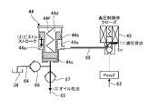
- the second outlet channel 63 is also connected to a second back pressure chamber 44 e of the accumulator 44 described later, and the accumulator 44 is utilized using the hydraulic pressure Peop2 output from the electric pump 33.
- the back pressure is adjustable. Note that the hydraulic pressure Peop1 discharged from the electric pump 33 to the outlet flow path 37 and the hydraulic pressure Peop2 discharged to the second outlet flow path 63 are the same.
- the accumulator 44 is connected on the hydraulic path 36 (preferably the fifth oil path 36e) connected to the C1 control system 18.
- the accumulator 44 is configured to store and hold (accumulate) the hydraulic pressure therein and supply (discharge) the held hydraulic pressure to the C1 control system 18 as necessary.
- the accumulator 44 includes a stepped piston 44b fitted in a stepped cylinder 44a so as to be slidable in one direction. Due to the small diameter portion of the stepped piston 44b, a pressure accumulation chamber 44c for accumulating oil is formed at the small diameter side end portion in the stepped cylinder 44a, and the volume of the pressure accumulation chamber 44c can be changed by the movement of the stepped piston 44b. It is configured.
- the accumulator 44 has a pressure accumulating chamber 44 c connected to a pressure accumulating oil path 64 for sucking and accumulating oil stored in the drain 34 and a discharge oil path 65 for discharging the accumulated oil to the hydraulic path 36. ing.
- a check valve 66 is provided on the pressure accumulating oil passage 64 to prevent oil from flowing out to the drain 34 side during discharge.
- a check valve 67 pressure accumulation check valve is provided on the discharge oil passage 65 to prevent oil from flowing from the hydraulic path 36 to the accumulator 44 during pressure accumulation.
- the pressure (accumulator pressure) Pacc of the oil accumulated in the accumulator 44 is detected.
- a pressure sensor 46 is provided and configured to transmit information of the detected accumulator pressure Pacc to the ECU 7.
- a first back pressure chamber 44d is formed by the large diameter portion of the stepped piston 44b at the large diameter side end portion in the stepped cylinder 44a of the accumulator 44.
- the first back pressure chamber 44d is provided with a spring 44f for urging the stepped piston 44b toward the pressure accumulating chamber 44c, and the urging force is changed according to the deformation of the spring 44f due to the sliding of the stepped piston 44b. In other words, the back pressure can be changed.
- the stepped piston 44b is pushed in to expand the volume of the accumulator 44c and the oil is stored inside. This back pressure and the pressure of the oil accumulated in the accumulator 44c (accumulator pressure Pacc. ) Is balanced.
- the accumulator 44 is discharged, the accumulated oil is discharged from the inside by pushing out the piston using the biasing force of the spring 44 f and supplied to the C1 control system 18.
- the back pressure that can be generated by the spring 44f has a maximum value when the large-diameter side end surface of the stepped piston 44b abuts against the large-diameter side end of the stepped cylinder 44a.
- the maximum value of the back pressure is adjusted, for example, by adjusting the spring length or spring constant of the spring 44f so that the clutch pressure Pc1 can be maintained at least at the packed pressure when oil is discharged from the accumulator 44. This can be set in advance.
- the “pack packing pressure” means that the clutch pack (the hydraulic oil chamber of the forward / reverse switching clutch C1) is filled with hydraulic oil so that the clutch plate of the forward / reverse switching clutch C1 comes into contact with (clogs) the friction material. This is the hydraulic pressure that can be generated.
- a second back pressure chamber 44e (back pressure chamber) is formed between the stepped portion of the stepped cylinder 44a of the accumulator 44 and the stepped portion of the stepped piston 44b.
- the accumulator 44 is configured to be able to adjust the back pressure of the stepped piston 44b by adjusting the amount of oil supplied to the second back pressure chamber 44e.
- the stepped piston 44b moves to the large-diameter side end of the stepped cylinder 44a, the volume of the pressure accumulating chamber 44c is expanded, and oil is supplied to the pressure accumulating chamber 44c. Is accumulated.
- the stepped piston 44b is moved to the small diameter side end portion of the stepped cylinder 44a by the urging force of the spring 44f, and the volume of the pressure accumulating chamber 44c is reduced, thereby accumulating pressure. Oil is discharged from the chamber 44c. That is, the oil pressure of the oil supplied to the second back pressure chamber 44e functions as an operating pressure that switches between accumulator 44 discharge and discharge.
- the second back pressure chamber 44e is connected to a back pressure control oil passage 68 (oil passage), and oil is introduced / discharged through the back pressure control oil passage 68.
- a second outlet passage 63 is connected to the back pressure control oil passage 68, and the oil of the oil pressure Peop 2 output from the electric pump 33 passes through the second outlet passage 63 and the back pressure control oil passage 68. Via the second back pressure chamber 44e.
- On the back pressure control oil passage 68 there is provided a pressure accumulation control valve 45 for controlling oil supply to the second back pressure chamber 44e of the accumulator 44 or oil discharge from the second back pressure chamber 44e.
- the pressure accumulation control valve 45 is, for example, a solenoid valve having three ports, and is a so-called three-way on / off valve that can switch a port that communicates depending on energization / non-energization.
- Each port of the pressure accumulation control valve 45 is connected to the second outlet flow path 63, the back pressure control oil path 68, and the discharge port Ex.
- the second outlet flow path 63 and the back pressure control oil path 68 are connected.
- this state is assumed to be the state in which the pressure accumulation control valve 45 is opened (opened)), and the back pressure control oil passage 68 and the discharge port Ex are communicated when not energized. This is a state (in the following description, this state is a state in which the pressure accumulation control valve 45 is closed).
- the pressure accumulation and discharge operation of the accumulator 44 is controlled by this pressure accumulation control valve 45.
- a mechanism for accumulating the accumulator 44 will be described with reference to FIG. As shown in FIG. 4, when the pressure accumulation control valve 45 is opened, the second outlet flow path 63 and the back pressure control oil path 68 communicate with each other, so that the second back pressure chamber 44e of the accumulator 44 is electrically driven.
- the hydraulic pressure Peop2 output from the pump 33 is supplied (indicated as “(1) hydraulic pressure supply” in FIG. 4).
- the back pressure becomes the maximum value, and the oil pressure (accumulator pressure Pacc) in the pressure accumulation chamber 44c is balanced with the back pressure.
- Maximum value As described above, the maximum value of the back pressure is a pressure that can maintain the clutch pressure Pc1 at least at the pack packing pressure when the oil is discharged from the accumulator 44. Therefore, the oil accumulated in the accumulator 44 at this time
- the accumulator pressure Pacc which is the same pressure, is also equivalent.
- FIG. 5 shows “(1) Hydraulic pressure discharge”.
- the stepped piston 44b moves in a direction to reduce the volume of the pressure accumulating chamber 44c by the urging force of the spring 44f ("(2) piston stroke” in FIG. 5).
- the oil accumulated in the accumulator 44c of the accumulator 44 is discharged to the discharge oil passage 65 (shown as “(3) oil discharge” in FIG. 5).
- oil checkout to the drain 34 side is prevented by the check valve 66 of the pressure accumulation oil passage 64.
- the opening / closing operation of the pressure accumulation control valve 45 is controlled by the ECU 7.
- the pressure accumulation control valve 45 can be switched between open and closed by adjusting the supply current by the ECU 7.
- the pressure accumulation control valve 45 switches between “a state in which the second outlet passage 63 and the back pressure control oil passage 68 are in communication” and “a state in which the back pressure control oil passage 68 and the discharge port are in communication”.
- Other valve structures such as a spool valve may be used, or a plurality of valve structures may be used in combination, for example, an on / off valve having two ports and a switching valve for switching the connection path.
- the position where the accumulator 44 (discharge oil passage 65) is connected to the hydraulic passage 36 is upstream of the SLC linear solenoid 60, preferably LPM No. More downstream than the two valves 54, more preferably downstream from the branch of the fifth oil passage 36 e of the hydraulic passage 36 with the sixth oil passage 36 f. Further, a check valve 59 is provided upstream of the connection position of the accumulator 44 on the hydraulic path 36 (a position downstream of the sixth oil path 36f in the example of FIG. 2), and the oil discharged from the accumulator 44 is The configuration is such that backflow to the upstream side is prevented, and the hydraulic pressure Plpm2 can be efficiently increased by the accumulator 44.
- the control device 1 in particular, the mechanical pump 31, the electric pump 33, and the accumulator 44 functions as the vehicle control device according to the present embodiment.
- deceleration S & S control (idling stop traveling) is being executed (S101).
- the execution period of the deceleration S & S control can be, for example, a period from an engine stop instruction at the start of control to an engine start completion determination at the end of control.
- the process proceeds to step S102.
- the deceleration S & S control is being executed (Yes in S101)
- the process proceeds to step S108.
- step S101 If it is determined in step S101 that the deceleration S & S control is not executed, it is confirmed whether or not the current vehicle speed is equal to or lower than the vehicle speed at which the deceleration S & S control is permitted (S & S permitted vehicle speed). (S102). If the vehicle speed is greater than the S & S permitted vehicle speed (No in S102), the process proceeds to step S103. When the vehicle speed is equal to or lower than the S & S permission vehicle speed (Yes in S102), the process proceeds to step S106.
- step S102 If it is determined in step S102 that the vehicle speed is greater than the S & S permitted vehicle speed, it is confirmed whether fuel cut control is being executed or whether the vehicle speed is equal to or less than a predetermined value (S103). ).
- the predetermined value is set to a value equal to or higher than the S & S permission vehicle speed used in step S102.
- the process proceeds to step S105. In other cases (No in S103), the process proceeds to step S104.
- step S104 When the condition of step S104 is not satisfied, the driving of the electric pump 33 is stopped, the pressure accumulation control valve 45 is closed, and the execution of the deceleration S & S control is prohibited (S104).
- step S104 when the condition of step S104 is satisfied, the electric pump 33 is driven, the pressure accumulation control valve 45 is opened (S105), and the pressure accumulation process of the accumulator 44 described with reference to FIG. 4 is started. . That is, in the present embodiment, when the vehicle speed falls within the range from the S & S permission vehicle speed to the predetermined value, the pressure accumulation process of the accumulator 44 can be started.
- step S102 If it is determined in step S102 that the vehicle speed is equal to or lower than the S & S permission vehicle speed, it is confirmed whether or not a condition (S & S start permission condition) for allowing execution of deceleration S & S control other than the vehicle speed is satisfied.
- S106 The S & S start permission condition is set for various information such as brake / accelerator operation, vehicle deceleration state, battery state, oil temperature, engine coolant temperature, and the like.
- the process proceeds to step S107. If the S & S start permission condition is not satisfied (No in S106), the process ends.
- step S106 When it is determined in step S106 that the S & S start permission condition is satisfied, the deceleration S & S control is executed (S107), and the opening control of the C1 control system 18 and the engine stop control are performed. At this time, the electric pump 33 driving and the pressure accumulation control valve open state implemented in step S105 are maintained, and the accumulator 44 continues to accumulate pressure.
- step S101 If it is determined in step S101 that the deceleration S & S control is being executed, it is confirmed whether or not an S & S return request has been made (S108).
- the S & S return request is a command to return from deceleration S & S control to normal engine travel control. For example, the trigger is triggered by a state in which the brake is turned off, the negative pressure of the brake is reduced, or the battery voltage is reduced. Can be detected. If there is an S & S return request (Yes in S108), the process proceeds to step S109. If there is no S & S return request (No in S108), the process ends.
- step S108 If it is determined in step S108 that an S & S return request has been made, restart control of the engine 3 is started, and the pressure accumulation control valve 45 is closed (S109), and the accumulator 44 described with reference to FIG. The discharge process is executed.
- the C1 packing control for increasing the clutch pressure Pc1 supplied to the C1 control system 18 to the packing pressure by the oil discharged from the accumulator 44 can be performed.
- the hydraulic control device 1 of this embodiment is mounted on a vehicle 2 including an engine 3 and a power transmission device 5 including a continuously variable transmission mechanism 11 and a C1 control system 18 (forward / reverse switching clutch C1).
- the oil pressure of oil supplied to operate 5 is controlled.
- the vehicle 2 can execute an idling stop function for stopping the engine 3 and releasing the C1 control system 18 (forward / reverse switching clutch C1) not only when the vehicle is stopped, but also when the vehicle is traveling, such as during deceleration. is there.
- the belt-type continuously variable transmission mechanism 11 of the power transmission device 5 can secure a belt clamping pressure that is not affected by cranking when the engine is restarted.
- a hydraulic pressure of about 0.3 MPa is required as the secondary pressure Pd supplied to the secondary sheave 21a that controls the belt clamping pressure.
- the electric pump 33 is very It needs to be bigger.
- the electric pump needs about 25 times the volume to generate 5 times the hydraulic pressure when the vehicle is stopped, and the power consumption is several tens for the idling stop function when the vehicle is stopped.
- an electric pump with a power consumption of kilowatts is required for the idling stop function when the vehicle is running.
- the C1 control system 18 forward / reverse switching clutch C1 is brought into a state in which it can be quickly restarted (operational state, clutch pack packed state) until the engine restart is completed. It is desirable to ensure the control response of the C1 control system 18.
- the hydraulic control device 1 of the present embodiment includes an electric pump 33 that supplies oil to the belt-type continuously variable transmission mechanism 11 of the power transmission device 5 through the hydraulic path 36 by driving the motor 32, and the electric pump 33.
- An accumulator 44 that accumulates oil inside using the supplied oil, and discharges the accumulated oil via a hydraulic path 36 and supplies the accumulated oil to the C1 control system 18.
- the electric pump 33 supplies oil directly to the continuously variable transmission mechanism 11, it is possible to reduce the leakage flow rate from the electric pump 33 to the continuously variable transmission mechanism 11, and the electric pump 33 can be downsized. It becomes possible.
- the oil accumulated by the accumulator 44 is supplied to the C1 control system 18, so that the engine restart is completed when returning from the idling stop state.
- the C1 control system 18 (forward / reverse switching clutch C1) must be in a state in which it can be restarted quickly (operational state, clutch pack packed state) to ensure control response of the C1 control system 18 Can do.
- the timing of oil supply from the accumulator 44 can be limited to a short time from the end of idling stop travel to the engine restart, the accumulated pressure in the accumulator 44 is lower than the belt clamping pressure in the C1 control system 18. Since it is used for control, the accumulator 44 can be downsized.
- the hydraulic control device 1 of the present embodiment it is possible to suppress an increase in the size of the electric pump 33 and the accumulator 44 used for hydraulic control when the idling stop function is executed.
- the accumulator 44 is configured to accumulate oil inside using the oil supplied by the electric pump 33, it is possible to accumulate pressure without consuming oil discharged from the mechanical pump 31. For this reason, for example, even when the discharge flow rate by the mechanical pump 31 is small, such as when the engine speed is low, when the line pressure PL is instructed to increase, or when the oil temperature is high, the hydraulic pressure regulation characteristics and response of the hydraulic control device 1 by the pressure accumulation operation Therefore, it is possible to reduce pressure on the accumulator 44. As a result, it is possible to increase the timing at which the accumulator 44 can accumulate pressure.
- the mechanical pump 31 is stopped during the idling stop function and the pressure accumulation process cannot be performed. Due to the influence, there is a possibility that the accumulator pressure Pacc, which is the oil pressure of the oil accumulated in the accumulator 44, is lowered.
- the accumulator pressure Pacc needs to be maintained to such an extent that the clutch pressure Pc1 can be increased to the pack packing pressure when returning from the idling stop function, and therefore the idling stop function may not be continued for a long time.
- the accumulator 44 is configured to accumulate oil inside using the oil supplied by the electric pump 33, so that accumulation can be performed even when the idling stop function in which the engine 3 is stopped is being executed. For this reason, even when the accumulator pressure Pacc is reduced due to the influence of oil leakage or the like, the accumulator 44 can appropriately accumulate pressure, so that it is possible to suppress the duration of the idling stop function from being shortened, and the idling stop function can be implemented for a long period of time.
- the accumulator 44 uses the oil supplied from the electric pump 33 as an operating pressure to store and discharge the oil.
- the oil discharged from the electric pump 33 is not directly introduced into the accumulator 44 and accumulated, but simply used as an operating pressure. Therefore, the accumulator can be operated without increasing the discharge flow rate of the electric pump 33. It is possible to control accumulation, holding pressure, discharge, and the like, and it is possible to increase the efficiency of accumulator control.
- the hydraulic control device 1 is configured so that the oil supplied by the electric pump 33 communicates with the second back pressure chamber 44e that adjusts the back pressure of the accumulator 44 so that the oil can be introduced. 68, and a pressure accumulation control valve 45 provided on the back pressure control oil passage 68 and controlling introduction of oil into the second back pressure chamber 44e or discharge of oil from the second back pressure chamber 44e. .
- the accumulator 44 accumulates oil inside the accumulator 44 when the oil supplied from the electric pump 33 is introduced from the back pressure control oil passage 68 to the second back pressure chamber 44e by the pressure accumulation control valve 45. In a state where oil is discharged from the second back pressure chamber 44e to the back pressure control oil passage 68 by the control valve 45, the oil accumulated inside is discharged to the hydraulic passage 36 and supplied to the C1 control system 18.
- the amount of oil used for accumulator control can be limited to the amount that can be introduced into the second back pressure chamber 44e of the accumulator 44, so that the efficiency of accumulator control can be further improved.
- the oil supply and discharge of the second back pressure chamber 44e can be switched to control the pressure accumulation, pressure holding, and discharge of the accumulator 44. It can be executed with high accuracy.
- the hydraulic control apparatus 1 includes a check valve 67 that is provided between the accumulator 44 and the hydraulic path 36 and prevents the flow of oil from the hydraulic path 36 side to the accumulator 44.
- FIG. 7 is a diagram showing a schematic configuration of a hydraulic control device 1a according to the second embodiment of the present invention.
- the hydraulic control device 1a of the present embodiment is different from the hydraulic control device 1 of the first embodiment in that the oil supplied by the electric pump 33 is accumulated in the accumulator 84.
- the accumulator 84 of the present embodiment may have the same configuration as the accumulator 44 of the first embodiment, or may have another known configuration.
- FIG. 7 exemplifies a piston-type accumulator 84 having a configuration in which a piston 84b is slidably disposed inside a cylinder 84a and oil is stored in a pressure accumulation chamber 84c formed by the piston 84b and the cylinder 84a. Yes.
- the accumulator 84 c of the accumulator 84 is connected to the accumulator oil passage 74 and the discharge oil passage 75.
- the pressure accumulating oil passage 74 is an oil passage that is connected to the second outlet passage 63 of the electric pump 33 and communicated so that oil supplied by the electric pump 33 can be introduced into the accumulator 84.
- a check valve 76 is provided on the pressure accumulating oil passage 74 to prevent oil from flowing out to the electric pump 33 during discharge.
- the discharge oil passage 75 is an oil passage for discharging the oil accumulated in the accumulator 84 to the hydraulic passage 36. Similar to the discharge oil passage 65 of the first embodiment, the discharge oil passage 75 is upstream of the SLC linear solenoid 60, preferably LPM No.
- the hydraulic path 36 is connected to the downstream side of the two valves 54, more preferably, downstream of the fifth oil path 36 e of the hydraulic path 36 from the branch with the sixth oil path 36 f.
- a pressure accumulation control valve 85 (switching valve) for switching communication and shutoff between the accumulator 84 and the hydraulic passage 36 is provided.
- the opening / closing operation of the pressure accumulation control valve 85 is controlled by the ECU 7.
- the pressure accumulation control valve 85 is an electromagnetic poppet valve as shown in FIG. 7, for example, and can be opened and closed by adjusting a supply current by the ECU 7.
- the pressure accumulation control valve 85 may use another valve structure such as a spool valve.
- Accumulation of oil to the accumulator 84 and discharge of oil from the accumulator 84 are controlled by operations of the accumulator control valve 85 and the electric pump 33.
- the pressure accumulation control valve 85 When the pressure accumulation control valve 85 is closed (closed), the accumulator 84 and the hydraulic path 36 are shut off. If the electric pump 33 is driven at this time, the oil discharged from the electric pump 33 is introduced into the pressure accumulation chamber 84c of the accumulator 84 via the second outlet flow path 63 and the pressure accumulation oil path 74 and accumulated. .
- the hydraulic control device 1a is configured to supply oil to the continuously variable transmission mechanism 11 by the electric pump 33 and supply oil to the C1 control system 18 by the accumulator 84, as in the first embodiment. Further, it is possible to suppress an increase in the size of the electric pump 33 and the accumulator 44 used for hydraulic control when the idling stop function is executed.
- the accumulator 84 uses oil supplied by the electric pump 33 (more specifically, accumulates oil supplied by the electric pump 33) and supplies oil therein. Since the pressure is accumulated, the pressure can be accumulated without consuming the oil discharged from the mechanical pump 31. For this reason, for example, even when the discharge flow rate by the mechanical pump 31 is small, such as when the engine speed is low, when the line pressure PL is instructed to increase, or when the oil temperature is high, the hydraulic pressure regulation characteristics and response of the hydraulic control device 1 by the pressure accumulation operation Therefore, it is possible to reduce pressure on the accumulator 84. As a result, it is possible to expand the timing at which the accumulator 44 can accumulate pressure.
- the mechanical pump 31 is stopped during the idling stop function and the pressure accumulation process cannot be performed.
- the hydraulic pressure Pacc of the oil accumulated in the accumulator 84 may decrease due to the influence.
- the accumulated hydraulic pressure in the accumulator 84 needs to be maintained to such an extent that the clutch pressure Pc1 can be increased to the pack packing pressure when returning from the idling stop function, and therefore the idling stop function may not be continued for a long time.
- the accumulator 84 is configured to accumulate oil inside using the oil supplied by the electric pump 33, so that accumulation can be performed even when the idling stop function in which the engine 3 is stopped is being executed. For this reason, even when the accumulator pressure Pacc is lowered due to the influence of oil leakage or the like, the pressure can be appropriately accumulated, so that the idling stop function can be implemented for a long period of time.
- the hydraulic control device 1a connects the accumulator 84 and the hydraulic path 36 to each other, and the accumulator 84 and the hydraulic path 36 are connected to the accumulator 84 so that the oil supplied by the electric pump 33 can be introduced into the accumulator 84.
- An oil passage 75 and a pressure accumulation control valve 85 that is provided on the discharge oil passage 75 and switches communication between the accumulator 84 and the hydraulic passage 36 are provided.
- the accumulator 84 accumulates the oil supplied from the pressure accumulation oil passage 74 by the electric pump 33 when the electric pump 33 is driven and is blocked from the hydraulic pressure path 36 by the pressure accumulation control valve 85, and accumulate pressure control.
- the oil accumulated inside is discharged to the hydraulic path 36 via the discharge oil path 75 and supplied to the C1 control system 18.
- the C1 control system 18 (forward / reverse switching clutch C1 and forward / reverse switching brake B1) of the forward / reverse switching mechanism 10 is illustrated as a clutch hydraulically controlled together with the continuously variable transmission mechanism 11 by the hydraulic control devices 1 and 1a.
- this clutch can cut off the rotational torque between the engine 3 and the drive wheel 4 in the released state, and can transmit the torque between the engine 3 and the drive wheel 4 in the engaged state.
- a clutch other than the forward / reverse switching mechanism 10 may be used.
- the electric pump 33 may be connected to the hydraulic path 36 so that oil can be supplied to the sheave for controlling the belt clamping pressure of the continuously variable transmission mechanism 11.
- the electric pump 33 since the secondary sheave 21a exemplifies the configuration for controlling the belt clamping pressure, the electric pump 33 is connected to the second oil passage 36b that supplies oil to the secondary sheave 21a.
- the electric pump 33 can be connected to the first oil passage 36a that supplies oil to the primary sheave 20a.
Landscapes
- Engineering & Computer Science (AREA)
- General Engineering & Computer Science (AREA)
- Mechanical Engineering (AREA)
- Physics & Mathematics (AREA)
- Fluid Mechanics (AREA)
- Control Of Transmission Device (AREA)
Abstract
Priority Applications (5)
| Application Number | Priority Date | Filing Date | Title |
|---|---|---|---|
| CN201180075631.4A CN103998827B (zh) | 2011-12-26 | 2011-12-26 | 液压控制装置及车辆控制装置 |
| PCT/JP2011/080090 WO2013098922A1 (fr) | 2011-12-26 | 2011-12-26 | Dispositif de commande hydraulique et dispositif de commande de véhicule |
| US14/366,751 US9528600B2 (en) | 2011-12-26 | 2011-12-26 | Hydraulic control device and vehicle control device |
| JP2013551063A JP5716845B2 (ja) | 2011-12-26 | 2011-12-26 | 油圧制御装置及び車両制御装置 |
| EP11878585.6A EP2799742B1 (fr) | 2011-12-26 | 2011-12-26 | Dispositif de commande hydraulique et dispositif de commande de véhicule |
Applications Claiming Priority (1)
| Application Number | Priority Date | Filing Date | Title |
|---|---|---|---|
| PCT/JP2011/080090 WO2013098922A1 (fr) | 2011-12-26 | 2011-12-26 | Dispositif de commande hydraulique et dispositif de commande de véhicule |
Publications (1)
| Publication Number | Publication Date |
|---|---|
| WO2013098922A1 true WO2013098922A1 (fr) | 2013-07-04 |
Family
ID=48696492
Family Applications (1)
| Application Number | Title | Priority Date | Filing Date |
|---|---|---|---|
| PCT/JP2011/080090 WO2013098922A1 (fr) | 2011-12-26 | 2011-12-26 | Dispositif de commande hydraulique et dispositif de commande de véhicule |
Country Status (5)
| Country | Link |
|---|---|
| US (1) | US9528600B2 (fr) |
| EP (1) | EP2799742B1 (fr) |
| JP (1) | JP5716845B2 (fr) |
| CN (1) | CN103998827B (fr) |
| WO (1) | WO2013098922A1 (fr) |
Cited By (5)
| Publication number | Priority date | Publication date | Assignee | Title |
|---|---|---|---|---|
| CN103807433A (zh) * | 2014-03-04 | 2014-05-21 | 湖南江麓容大车辆传动股份有限公司 | 液压控制回路及无级变速器的液压控制系统 |
| JPWO2013105233A1 (ja) * | 2012-01-11 | 2015-05-11 | トヨタ自動車株式会社 | 油圧制御装置及び車両制御装置 |
| JP2016145586A (ja) * | 2015-02-06 | 2016-08-12 | 富士重工業株式会社 | 油圧供給装置及び油圧供給装置の制御方法 |
| CN111102349A (zh) * | 2018-10-29 | 2020-05-05 | 丰田自动车株式会社 | 车辆用驱动装置的液压控制回路 |
| JP2020076448A (ja) * | 2018-11-07 | 2020-05-21 | ジヤトコ株式会社 | 車両制御装置 |
Families Citing this family (14)
| Publication number | Priority date | Publication date | Assignee | Title |
|---|---|---|---|---|
| JP2014185751A (ja) * | 2013-03-25 | 2014-10-02 | Jatco Ltd | 無段変速機の制御装置及び制御方法 |
| DE102014204067A1 (de) * | 2014-03-06 | 2015-09-10 | Zf Friedrichshafen Ag | Verfahren zum Ansteuern eines Hydraulikmittelversorgungssystems eines Automatikgetriebes |
| US20180003197A1 (en) * | 2015-01-26 | 2018-01-04 | Borgwarner Inc. | Accumulator and method of making and using the same |
| JP6493050B2 (ja) * | 2015-07-16 | 2019-04-03 | トヨタ自動車株式会社 | 車両用無段変速機の油圧制御装置 |
| JP6190858B2 (ja) * | 2015-09-24 | 2017-08-30 | 本田技研工業株式会社 | 油圧回路の制御装置 |
| US9834217B2 (en) | 2015-10-28 | 2017-12-05 | Ford Global Technologies, Llc | System and method for performing an engine stop and start for a rolling vehicle |
| FR3043717B1 (fr) * | 2015-11-13 | 2019-09-13 | Total Marketing Services | Systeme de motorisation et vehicule automobile associe |
| JP6333298B2 (ja) * | 2016-03-03 | 2018-05-30 | 本田技研工業株式会社 | 車両の油圧制御装置 |
| EP3546803B1 (fr) * | 2016-11-24 | 2020-09-30 | Nissan Motor Co., Ltd. | Procédé de commande d'une transmission à variation continue, et système de transmission à variation continue |
| WO2018216649A1 (fr) | 2017-05-22 | 2018-11-29 | アイシン・エィ・ダブリュ株式会社 | Dispositif de transmission d'énergie et procédé permettant de commander ce dernier |
| KR102417342B1 (ko) * | 2017-10-19 | 2022-07-05 | 현대자동차 주식회사 | 차량용 자동변속기의 유압공급시스템 |
| JP2019120308A (ja) * | 2017-12-28 | 2019-07-22 | 日産自動車株式会社 | 動力伝達装置の制御方法及び動力伝達装置の制御装置 |
| US11965593B2 (en) * | 2020-11-02 | 2024-04-23 | Jatco Ltd | Damping pressure supply circuit for pulley pressure control valve |
| WO2022091637A1 (fr) * | 2020-11-02 | 2022-05-05 | ジヤトコ株式会社 | Structure de disposition de soupape pour unité de soupape de commande |
Citations (6)
| Publication number | Priority date | Publication date | Assignee | Title |
|---|---|---|---|---|
| JP2002115755A (ja) | 2000-10-06 | 2002-04-19 | Toyota Motor Corp | 車両の油圧制御装置 |
| JP2002130449A (ja) | 2000-10-27 | 2002-05-09 | Toyota Motor Corp | 車両の油圧制御装置 |
| JP2006052766A (ja) * | 2004-08-10 | 2006-02-23 | Toyota Motor Corp | 油圧制御装置 |
| JP2010151226A (ja) | 2008-12-25 | 2010-07-08 | Aisin Aw Co Ltd | 車両用駆動装置 |
| JP2010151238A (ja) * | 2008-12-25 | 2010-07-08 | Aisin Aw Co Ltd | 車両用駆動装置 |
| JP2011132993A (ja) * | 2009-12-22 | 2011-07-07 | Toyota Motor Corp | 油圧制御装置 |
Family Cites Families (6)
| Publication number | Priority date | Publication date | Assignee | Title |
|---|---|---|---|---|
| JP2001193661A (ja) * | 1999-06-08 | 2001-07-17 | Denso Corp | 作動油供給システムおよびその制御方法 |
| DE60230904D1 (de) * | 2001-11-08 | 2009-03-05 | Hitachi Ltd | Getriebe mit einer Steuereinheit |
| JP2004084928A (ja) * | 2002-07-05 | 2004-03-18 | Aisin Aw Co Ltd | 変速機の油圧制御装置 |
| JP4821864B2 (ja) * | 2009-02-13 | 2011-11-24 | トヨタ自動車株式会社 | 自動変速機構の変速制御装置 |
| JP2010281432A (ja) * | 2009-06-08 | 2010-12-16 | Toyota Central R&D Labs Inc | 自動変速機の油圧供給装置 |
| JP5445309B2 (ja) * | 2010-04-28 | 2014-03-19 | トヨタ自動車株式会社 | 車両用油圧制御装置 |
-
2011
- 2011-12-26 EP EP11878585.6A patent/EP2799742B1/fr active Active
- 2011-12-26 US US14/366,751 patent/US9528600B2/en active Active
- 2011-12-26 WO PCT/JP2011/080090 patent/WO2013098922A1/fr active Application Filing
- 2011-12-26 JP JP2013551063A patent/JP5716845B2/ja not_active Expired - Fee Related
- 2011-12-26 CN CN201180075631.4A patent/CN103998827B/zh not_active Expired - Fee Related
Patent Citations (6)
| Publication number | Priority date | Publication date | Assignee | Title |
|---|---|---|---|---|
| JP2002115755A (ja) | 2000-10-06 | 2002-04-19 | Toyota Motor Corp | 車両の油圧制御装置 |
| JP2002130449A (ja) | 2000-10-27 | 2002-05-09 | Toyota Motor Corp | 車両の油圧制御装置 |
| JP2006052766A (ja) * | 2004-08-10 | 2006-02-23 | Toyota Motor Corp | 油圧制御装置 |
| JP2010151226A (ja) | 2008-12-25 | 2010-07-08 | Aisin Aw Co Ltd | 車両用駆動装置 |
| JP2010151238A (ja) * | 2008-12-25 | 2010-07-08 | Aisin Aw Co Ltd | 車両用駆動装置 |
| JP2011132993A (ja) * | 2009-12-22 | 2011-07-07 | Toyota Motor Corp | 油圧制御装置 |
Cited By (6)
| Publication number | Priority date | Publication date | Assignee | Title |
|---|---|---|---|---|
| JPWO2013105233A1 (ja) * | 2012-01-11 | 2015-05-11 | トヨタ自動車株式会社 | 油圧制御装置及び車両制御装置 |
| CN103807433A (zh) * | 2014-03-04 | 2014-05-21 | 湖南江麓容大车辆传动股份有限公司 | 液压控制回路及无级变速器的液压控制系统 |
| JP2016145586A (ja) * | 2015-02-06 | 2016-08-12 | 富士重工業株式会社 | 油圧供給装置及び油圧供給装置の制御方法 |
| CN111102349A (zh) * | 2018-10-29 | 2020-05-05 | 丰田自动车株式会社 | 车辆用驱动装置的液压控制回路 |
| CN111102349B (zh) * | 2018-10-29 | 2021-09-03 | 丰田自动车株式会社 | 车辆用驱动装置的液压控制回路 |
| JP2020076448A (ja) * | 2018-11-07 | 2020-05-21 | ジヤトコ株式会社 | 車両制御装置 |
Also Published As
| Publication number | Publication date |
|---|---|
| US9528600B2 (en) | 2016-12-27 |
| EP2799742A1 (fr) | 2014-11-05 |
| CN103998827B (zh) | 2016-04-06 |
| EP2799742B1 (fr) | 2020-01-22 |
| JP5716845B2 (ja) | 2015-05-13 |
| US20140371012A1 (en) | 2014-12-18 |
| JPWO2013098922A1 (ja) | 2015-04-30 |
| CN103998827A (zh) | 2014-08-20 |
| EP2799742A4 (fr) | 2017-03-22 |
Similar Documents
| Publication | Publication Date | Title |
|---|---|---|
| JP5716845B2 (ja) | 油圧制御装置及び車両制御装置 | |
| JP5786954B2 (ja) | 油圧制御装置 | |
| JP5218303B2 (ja) | 動力伝達装置 | |
| JP5761380B2 (ja) | 油圧制御装置及び車両制御装置 | |
| JP4192846B2 (ja) | 油圧制御装置 | |
| JP5610080B2 (ja) | 車両制御装置 | |
| JP6107930B2 (ja) | 車両の油圧制御装置 | |
| JP5630372B2 (ja) | 油圧制御装置 | |
| JP5742708B2 (ja) | 油圧制御装置及び車両制御装置 | |
| JP2007010090A (ja) | 油圧制御装置 | |
| JP5565526B2 (ja) | 油圧制御装置 | |
| JP2011094684A (ja) | オイル供給装置 | |
| JP7420531B2 (ja) | 車両 | |
| JP6730873B2 (ja) | 車両 | |
| KR100394679B1 (ko) | 자동차용 무단변속기의 유압 제어시스템 | |
| JP2004347015A (ja) | オイルポンプの油圧制御装置 | |
| JP2006009998A (ja) | 伝動機構の油圧制御装置 | |
| WO2014170743A1 (fr) | Dispositif de commande hydraulique d'une transmission à variation continue du type à courroie | |
| JP2014122670A (ja) | 油圧制御装置 |
Legal Events
| Date | Code | Title | Description |
|---|---|---|---|
| WWE | Wipo information: entry into national phase |
Ref document number: 201180075631.4 Country of ref document: CN |
|
| 121 | Ep: the epo has been informed by wipo that ep was designated in this application |
Ref document number: 11878585 Country of ref document: EP Kind code of ref document: A1 |
|
| ENP | Entry into the national phase |
Ref document number: 2013551063 Country of ref document: JP Kind code of ref document: A |
|
| WWE | Wipo information: entry into national phase |
Ref document number: 2011878585 Country of ref document: EP Ref document number: 14366751 Country of ref document: US |
|
| NENP | Non-entry into the national phase |
Ref country code: DE |