WO2013094260A1 - 空気極材料、インターコネクタ材料及び固体酸化物型燃料電池セル - Google Patents
空気極材料、インターコネクタ材料及び固体酸化物型燃料電池セル Download PDFInfo
- Publication number
- WO2013094260A1 WO2013094260A1 PCT/JP2012/073682 JP2012073682W WO2013094260A1 WO 2013094260 A1 WO2013094260 A1 WO 2013094260A1 JP 2012073682 W JP2012073682 W JP 2012073682W WO 2013094260 A1 WO2013094260 A1 WO 2013094260A1
- Authority
- WO
- WIPO (PCT)
- Prior art keywords
- air electrode
- fuel cell
- electrode material
- electrode
- solid oxide
- Prior art date
Links
- 239000007772 electrode material Substances 0.000 title claims abstract description 82
- 239000000446 fuel Substances 0.000 title claims description 121
- 239000000463 material Substances 0.000 title claims description 46
- 239000007787 solid Substances 0.000 title claims description 19
- 238000002149 energy-dispersive X-ray emission spectroscopy Methods 0.000 claims abstract description 8
- 239000000758 substrate Substances 0.000 claims description 43
- 239000002131 composite material Substances 0.000 claims description 23
- 238000009826 distribution Methods 0.000 claims description 20
- 229910052712 strontium Inorganic materials 0.000 claims description 11
- 238000010248 power generation Methods 0.000 claims description 10
- 229910052746 lanthanum Inorganic materials 0.000 claims description 9
- 229910052759 nickel Inorganic materials 0.000 claims description 8
- 229910052742 iron Inorganic materials 0.000 claims description 6
- 239000007784 solid electrolyte Substances 0.000 claims description 6
- 229910018921 CoO 3 Inorganic materials 0.000 claims description 3
- 229910003026 (La,Sr)(Co,Fe)O3 Inorganic materials 0.000 claims description 2
- 239000002994 raw material Substances 0.000 description 41
- 239000003792 electrolyte Substances 0.000 description 39
- 238000000034 method Methods 0.000 description 33
- 239000000654 additive Substances 0.000 description 27
- 239000000203 mixture Substances 0.000 description 24
- 239000011651 chromium Substances 0.000 description 23
- 230000004888 barrier function Effects 0.000 description 22
- KRKNYBCHXYNGOX-UHFFFAOYSA-N citric acid Chemical compound OC(=O)CC(O)(C(O)=O)CC(O)=O KRKNYBCHXYNGOX-UHFFFAOYSA-N 0.000 description 21
- 238000002156 mixing Methods 0.000 description 18
- 239000002245 particle Substances 0.000 description 17
- 238000004519 manufacturing process Methods 0.000 description 16
- 230000000996 additive effect Effects 0.000 description 15
- 230000006866 deterioration Effects 0.000 description 15
- PXHVJJICTQNCMI-UHFFFAOYSA-N nickel Substances [Ni] PXHVJJICTQNCMI-UHFFFAOYSA-N 0.000 description 15
- MCMNRKCIXSYSNV-UHFFFAOYSA-N Zirconium dioxide Chemical compound O=[Zr]=O MCMNRKCIXSYSNV-UHFFFAOYSA-N 0.000 description 14
- 239000000843 powder Substances 0.000 description 14
- 229910052796 boron Inorganic materials 0.000 description 12
- 230000015572 biosynthetic process Effects 0.000 description 11
- 229910052804 chromium Inorganic materials 0.000 description 11
- 238000010304 firing Methods 0.000 description 11
- 229910052698 phosphorus Inorganic materials 0.000 description 11
- 239000000523 sample Substances 0.000 description 9
- 238000005259 measurement Methods 0.000 description 8
- 238000003786 synthesis reaction Methods 0.000 description 8
- 239000007791 liquid phase Substances 0.000 description 7
- -1 oxygen ion Chemical class 0.000 description 7
- 238000010532 solid phase synthesis reaction Methods 0.000 description 7
- 239000000126 substance Substances 0.000 description 6
- 229910021193 La 2 O 3 Inorganic materials 0.000 description 5
- 238000004458 analytical method Methods 0.000 description 5
- 239000013025 ceria-based material Substances 0.000 description 5
- 238000000975 co-precipitation Methods 0.000 description 5
- 239000000470 constituent Substances 0.000 description 5
- 239000002737 fuel gas Substances 0.000 description 5
- 230000001590 oxidative effect Effects 0.000 description 5
- 229910052760 oxygen Inorganic materials 0.000 description 5
- 229910002080 8 mol% Y2O3 fully stabilized ZrO2 Inorganic materials 0.000 description 4
- 229910052684 Cerium Inorganic materials 0.000 description 4
- 229910020599 Co 3 O 4 Inorganic materials 0.000 description 4
- CETPSERCERDGAM-UHFFFAOYSA-N ceric oxide Chemical compound O=[Ce]=O CETPSERCERDGAM-UHFFFAOYSA-N 0.000 description 4
- 229910000422 cerium(IV) oxide Inorganic materials 0.000 description 4
- NFYLSJDPENHSBT-UHFFFAOYSA-N chromium(3+);lanthanum(3+);oxygen(2-) Chemical compound [O-2].[O-2].[O-2].[Cr+3].[La+3] NFYLSJDPENHSBT-UHFFFAOYSA-N 0.000 description 4
- 239000011362 coarse particle Substances 0.000 description 4
- 238000011156 evaluation Methods 0.000 description 4
- 239000001301 oxygen Substances 0.000 description 4
- 239000011148 porous material Substances 0.000 description 4
- 238000001878 scanning electron micrograph Methods 0.000 description 4
- LYCAIKOWRPUZTN-UHFFFAOYSA-N Ethylene glycol Chemical compound OCCO LYCAIKOWRPUZTN-UHFFFAOYSA-N 0.000 description 3
- 239000007864 aqueous solution Substances 0.000 description 3
- 239000003795 chemical substances by application Substances 0.000 description 3
- 238000009694 cold isostatic pressing Methods 0.000 description 3
- 238000005238 degreasing Methods 0.000 description 3
- 238000005516 engineering process Methods 0.000 description 3
- 229910021526 gadolinium-doped ceria Inorganic materials 0.000 description 3
- 150000002500 ions Chemical class 0.000 description 3
- 238000013507 mapping Methods 0.000 description 3
- 238000005245 sintering Methods 0.000 description 3
- 239000000243 solution Substances 0.000 description 3
- 239000013077 target material Substances 0.000 description 3
- CSCPPACGZOOCGX-UHFFFAOYSA-N Acetone Chemical compound CC(C)=O CSCPPACGZOOCGX-UHFFFAOYSA-N 0.000 description 2
- ZOXJGFHDIHLPTG-UHFFFAOYSA-N Boron Chemical compound [B] ZOXJGFHDIHLPTG-UHFFFAOYSA-N 0.000 description 2
- VYZAMTAEIAYCRO-UHFFFAOYSA-N Chromium Chemical compound [Cr] VYZAMTAEIAYCRO-UHFFFAOYSA-N 0.000 description 2
- 229910002554 Fe(NO3)3·9H2O Inorganic materials 0.000 description 2
- UFHFLCQGNIYNRP-UHFFFAOYSA-N Hydrogen Chemical compound [H][H] UFHFLCQGNIYNRP-UHFFFAOYSA-N 0.000 description 2
- 229910020851 La(NO3)3.6H2O Inorganic materials 0.000 description 2
- 229910002651 NO3 Inorganic materials 0.000 description 2
- NHNBFGGVMKEFGY-UHFFFAOYSA-N Nitrate Chemical compound [O-][N+]([O-])=O NHNBFGGVMKEFGY-UHFFFAOYSA-N 0.000 description 2
- OAICVXFJPJFONN-UHFFFAOYSA-N Phosphorus Chemical compound [P] OAICVXFJPJFONN-UHFFFAOYSA-N 0.000 description 2
- 229910052772 Samarium Inorganic materials 0.000 description 2
- QCWXUUIWCKQGHC-UHFFFAOYSA-N Zirconium Chemical compound [Zr] QCWXUUIWCKQGHC-UHFFFAOYSA-N 0.000 description 2
- PNEYBMLMFCGWSK-UHFFFAOYSA-N aluminium oxide Inorganic materials [O-2].[O-2].[O-2].[Al+3].[Al+3] PNEYBMLMFCGWSK-UHFFFAOYSA-N 0.000 description 2
- 239000012298 atmosphere Substances 0.000 description 2
- 229910052791 calcium Inorganic materials 0.000 description 2
- GWXLDORMOJMVQZ-UHFFFAOYSA-N cerium Chemical compound [Ce] GWXLDORMOJMVQZ-UHFFFAOYSA-N 0.000 description 2
- 238000007580 dry-mixing Methods 0.000 description 2
- 238000001035 drying Methods 0.000 description 2
- 230000000694 effects Effects 0.000 description 2
- 239000002001 electrolyte material Substances 0.000 description 2
- 239000007789 gas Substances 0.000 description 2
- 238000000227 grinding Methods 0.000 description 2
- 238000010438 heat treatment Methods 0.000 description 2
- 238000000265 homogenisation Methods 0.000 description 2
- 239000011574 phosphorus Substances 0.000 description 2
- 238000001556 precipitation Methods 0.000 description 2
- 238000002360 preparation method Methods 0.000 description 2
- 238000007639 printing Methods 0.000 description 2
- 238000010298 pulverizing process Methods 0.000 description 2
- 239000002002 slurry Substances 0.000 description 2
- 239000002904 solvent Substances 0.000 description 2
- XLYOFNOQVPJJNP-UHFFFAOYSA-N water Substances O XLYOFNOQVPJJNP-UHFFFAOYSA-N 0.000 description 2
- 229910001233 yttria-stabilized zirconia Inorganic materials 0.000 description 2
- RUDFQVOCFDJEEF-UHFFFAOYSA-N yttrium(III) oxide Inorganic materials [O-2].[O-2].[O-2].[Y+3].[Y+3] RUDFQVOCFDJEEF-UHFFFAOYSA-N 0.000 description 2
- 229910052726 zirconium Inorganic materials 0.000 description 2
- HXQQNYSFSLBXQJ-UHFFFAOYSA-N COC1=C(NC(CO)C(O)=O)CC(O)(CO)CC1=NCC(O)=O Chemical compound COC1=C(NC(CO)C(O)=O)CC(O)(CO)CC1=NCC(O)=O HXQQNYSFSLBXQJ-UHFFFAOYSA-N 0.000 description 1
- 229910052688 Gadolinium Inorganic materials 0.000 description 1
- 229910017563 LaCrO Inorganic materials 0.000 description 1
- 239000000853 adhesive Substances 0.000 description 1
- 230000001070 adhesive effect Effects 0.000 description 1
- 229910052782 aluminium Inorganic materials 0.000 description 1
- 229910052788 barium Inorganic materials 0.000 description 1
- 239000011230 binding agent Substances 0.000 description 1
- 238000007664 blowing Methods 0.000 description 1
- 238000009835 boiling Methods 0.000 description 1
- 238000001354 calcination Methods 0.000 description 1
- 230000015556 catabolic process Effects 0.000 description 1
- 239000003054 catalyst Substances 0.000 description 1
- 230000003197 catalytic effect Effects 0.000 description 1
- 239000010406 cathode material Substances 0.000 description 1
- 150000001768 cations Chemical class 0.000 description 1
- 239000001913 cellulose Substances 0.000 description 1
- 229920002678 cellulose Polymers 0.000 description 1
- 239000000919 ceramic Substances 0.000 description 1
- 229910000420 cerium oxide Inorganic materials 0.000 description 1
- 238000006243 chemical reaction Methods 0.000 description 1
- 238000010344 co-firing Methods 0.000 description 1
- 239000004020 conductor Substances 0.000 description 1
- 229910052802 copper Inorganic materials 0.000 description 1
- 238000006731 degradation reaction Methods 0.000 description 1
- 238000009792 diffusion process Methods 0.000 description 1
- 239000002270 dispersing agent Substances 0.000 description 1
- 239000002612 dispersion medium Substances 0.000 description 1
- 238000010292 electrical insulation Methods 0.000 description 1
- 230000007613 environmental effect Effects 0.000 description 1
- 229910052747 lanthanoid Inorganic materials 0.000 description 1
- 150000002602 lanthanoids Chemical class 0.000 description 1
- 229910052749 magnesium Inorganic materials 0.000 description 1
- 229910052748 manganese Inorganic materials 0.000 description 1
- 229910052751 metal Inorganic materials 0.000 description 1
- 239000002184 metal Substances 0.000 description 1
- 229910000480 nickel oxide Inorganic materials 0.000 description 1
- BMMGVYCKOGBVEV-UHFFFAOYSA-N oxo(oxoceriooxy)cerium Chemical compound [Ce]=O.O=[Ce]=O BMMGVYCKOGBVEV-UHFFFAOYSA-N 0.000 description 1
- GNRSAWUEBMWBQH-UHFFFAOYSA-N oxonickel Chemical compound [Ni]=O GNRSAWUEBMWBQH-UHFFFAOYSA-N 0.000 description 1
- 230000002093 peripheral effect Effects 0.000 description 1
- 238000005191 phase separation Methods 0.000 description 1
- 239000002243 precursor Substances 0.000 description 1
- 230000002265 prevention Effects 0.000 description 1
- 229910052761 rare earth metal Inorganic materials 0.000 description 1
- 229910001404 rare earth metal oxide Inorganic materials 0.000 description 1
- 150000002910 rare earth metals Chemical class 0.000 description 1
- 238000011946 reduction process Methods 0.000 description 1
- 238000002407 reforming Methods 0.000 description 1
- 238000007650 screen-printing Methods 0.000 description 1
- 229910002076 stabilized zirconia Inorganic materials 0.000 description 1
- 239000003381 stabilizer Substances 0.000 description 1
- 239000007858 starting material Substances 0.000 description 1
- 238000003756 stirring Methods 0.000 description 1
- 238000005728 strengthening Methods 0.000 description 1
- 238000012360 testing method Methods 0.000 description 1
- 229910052719 titanium Inorganic materials 0.000 description 1
- 229910052720 vanadium Inorganic materials 0.000 description 1
- 230000000007 visual effect Effects 0.000 description 1
- 238000005303 weighing Methods 0.000 description 1
- 229910052727 yttrium Inorganic materials 0.000 description 1
- 229910052725 zinc Inorganic materials 0.000 description 1
Images


Classifications
-
- H—ELECTRICITY
- H01—ELECTRIC ELEMENTS
- H01M—PROCESSES OR MEANS, e.g. BATTERIES, FOR THE DIRECT CONVERSION OF CHEMICAL ENERGY INTO ELECTRICAL ENERGY
- H01M4/00—Electrodes
- H01M4/86—Inert electrodes with catalytic activity, e.g. for fuel cells
- H01M4/8663—Selection of inactive substances as ingredients for catalytic active masses, e.g. binders, fillers
-
- B—PERFORMING OPERATIONS; TRANSPORTING
- B01—PHYSICAL OR CHEMICAL PROCESSES OR APPARATUS IN GENERAL
- B01J—CHEMICAL OR PHYSICAL PROCESSES, e.g. CATALYSIS OR COLLOID CHEMISTRY; THEIR RELEVANT APPARATUS
- B01J23/00—Catalysts comprising metals or metal oxides or hydroxides, not provided for in group B01J21/00
- B01J23/002—Mixed oxides other than spinels, e.g. perovskite
-
- B—PERFORMING OPERATIONS; TRANSPORTING
- B01—PHYSICAL OR CHEMICAL PROCESSES OR APPARATUS IN GENERAL
- B01J—CHEMICAL OR PHYSICAL PROCESSES, e.g. CATALYSIS OR COLLOID CHEMISTRY; THEIR RELEVANT APPARATUS
- B01J23/00—Catalysts comprising metals or metal oxides or hydroxides, not provided for in group B01J21/00
- B01J23/70—Catalysts comprising metals or metal oxides or hydroxides, not provided for in group B01J21/00 of the iron group metals or copper
- B01J23/76—Catalysts comprising metals or metal oxides or hydroxides, not provided for in group B01J21/00 of the iron group metals or copper combined with metals, oxides or hydroxides provided for in groups B01J23/02 - B01J23/36
- B01J23/83—Catalysts comprising metals or metal oxides or hydroxides, not provided for in group B01J21/00 of the iron group metals or copper combined with metals, oxides or hydroxides provided for in groups B01J23/02 - B01J23/36 with rare earths or actinides
-
- B—PERFORMING OPERATIONS; TRANSPORTING
- B01—PHYSICAL OR CHEMICAL PROCESSES OR APPARATUS IN GENERAL
- B01J—CHEMICAL OR PHYSICAL PROCESSES, e.g. CATALYSIS OR COLLOID CHEMISTRY; THEIR RELEVANT APPARATUS
- B01J35/00—Catalysts, in general, characterised by their form or physical properties
- B01J35/30—Catalysts, in general, characterised by their form or physical properties characterised by their physical properties
- B01J35/33—Electric or magnetic properties
-
- C—CHEMISTRY; METALLURGY
- C04—CEMENTS; CONCRETE; ARTIFICIAL STONE; CERAMICS; REFRACTORIES
- C04B—LIME, MAGNESIA; SLAG; CEMENTS; COMPOSITIONS THEREOF, e.g. MORTARS, CONCRETE OR LIKE BUILDING MATERIALS; ARTIFICIAL STONE; CERAMICS; REFRACTORIES; TREATMENT OF NATURAL STONE
- C04B35/00—Shaped ceramic products characterised by their composition; Ceramics compositions; Processing powders of inorganic compounds preparatory to the manufacturing of ceramic products
- C04B35/01—Shaped ceramic products characterised by their composition; Ceramics compositions; Processing powders of inorganic compounds preparatory to the manufacturing of ceramic products based on oxide ceramics
- C04B35/26—Shaped ceramic products characterised by their composition; Ceramics compositions; Processing powders of inorganic compounds preparatory to the manufacturing of ceramic products based on oxide ceramics based on ferrites
-
- H—ELECTRICITY
- H01—ELECTRIC ELEMENTS
- H01M—PROCESSES OR MEANS, e.g. BATTERIES, FOR THE DIRECT CONVERSION OF CHEMICAL ENERGY INTO ELECTRICAL ENERGY
- H01M4/00—Electrodes
- H01M4/86—Inert electrodes with catalytic activity, e.g. for fuel cells
- H01M4/90—Selection of catalytic material
- H01M4/9016—Oxides, hydroxides or oxygenated metallic salts
- H01M4/9025—Oxides specially used in fuel cell operating at high temperature, e.g. SOFC
- H01M4/9033—Complex oxides, optionally doped, of the type M1MeO3, M1 being an alkaline earth metal or a rare earth, Me being a metal, e.g. perovskites
-
- H—ELECTRICITY
- H01—ELECTRIC ELEMENTS
- H01M—PROCESSES OR MEANS, e.g. BATTERIES, FOR THE DIRECT CONVERSION OF CHEMICAL ENERGY INTO ELECTRICAL ENERGY
- H01M8/00—Fuel cells; Manufacture thereof
- H01M8/02—Details
- H01M8/0202—Collectors; Separators, e.g. bipolar separators; Interconnectors
- H01M8/0204—Non-porous and characterised by the material
- H01M8/0215—Glass; Ceramic materials
- H01M8/0217—Complex oxides, optionally doped, of the type AMO3, A being an alkaline earth metal or rare earth metal and M being a metal, e.g. perovskites
-
- B—PERFORMING OPERATIONS; TRANSPORTING
- B01—PHYSICAL OR CHEMICAL PROCESSES OR APPARATUS IN GENERAL
- B01J—CHEMICAL OR PHYSICAL PROCESSES, e.g. CATALYSIS OR COLLOID CHEMISTRY; THEIR RELEVANT APPARATUS
- B01J2523/00—Constitutive chemical elements of heterogeneous catalysts
-
- B—PERFORMING OPERATIONS; TRANSPORTING
- B01—PHYSICAL OR CHEMICAL PROCESSES OR APPARATUS IN GENERAL
- B01J—CHEMICAL OR PHYSICAL PROCESSES, e.g. CATALYSIS OR COLLOID CHEMISTRY; THEIR RELEVANT APPARATUS
- B01J27/00—Catalysts comprising the elements or compounds of halogens, sulfur, selenium, tellurium, phosphorus or nitrogen; Catalysts comprising carbon compounds
- B01J27/14—Phosphorus; Compounds thereof
- B01J27/186—Phosphorus; Compounds thereof with arsenic, antimony, bismuth, vanadium, niobium, tantalum, polonium, chromium, molybdenum, tungsten, manganese, technetium or rhenium
- B01J27/188—Phosphorus; Compounds thereof with arsenic, antimony, bismuth, vanadium, niobium, tantalum, polonium, chromium, molybdenum, tungsten, manganese, technetium or rhenium with chromium, molybdenum, tungsten or polonium
-
- C—CHEMISTRY; METALLURGY
- C04—CEMENTS; CONCRETE; ARTIFICIAL STONE; CERAMICS; REFRACTORIES
- C04B—LIME, MAGNESIA; SLAG; CEMENTS; COMPOSITIONS THEREOF, e.g. MORTARS, CONCRETE OR LIKE BUILDING MATERIALS; ARTIFICIAL STONE; CERAMICS; REFRACTORIES; TREATMENT OF NATURAL STONE
- C04B2235/00—Aspects relating to ceramic starting mixtures or sintered ceramic products
- C04B2235/02—Composition of constituents of the starting material or of secondary phases of the final product
- C04B2235/30—Constituents and secondary phases not being of a fibrous nature
- C04B2235/32—Metal oxides, mixed metal oxides, or oxide-forming salts thereof, e.g. carbonates, nitrates, (oxy)hydroxides, chlorides
- C04B2235/3205—Alkaline earth oxides or oxide forming salts thereof, e.g. beryllium oxide
- C04B2235/3213—Strontium oxides or oxide-forming salts thereof
-
- C—CHEMISTRY; METALLURGY
- C04—CEMENTS; CONCRETE; ARTIFICIAL STONE; CERAMICS; REFRACTORIES
- C04B—LIME, MAGNESIA; SLAG; CEMENTS; COMPOSITIONS THEREOF, e.g. MORTARS, CONCRETE OR LIKE BUILDING MATERIALS; ARTIFICIAL STONE; CERAMICS; REFRACTORIES; TREATMENT OF NATURAL STONE
- C04B2235/00—Aspects relating to ceramic starting mixtures or sintered ceramic products
- C04B2235/02—Composition of constituents of the starting material or of secondary phases of the final product
- C04B2235/30—Constituents and secondary phases not being of a fibrous nature
- C04B2235/32—Metal oxides, mixed metal oxides, or oxide-forming salts thereof, e.g. carbonates, nitrates, (oxy)hydroxides, chlorides
- C04B2235/3224—Rare earth oxide or oxide forming salts thereof, e.g. scandium oxide
- C04B2235/3227—Lanthanum oxide or oxide-forming salts thereof
-
- C—CHEMISTRY; METALLURGY
- C04—CEMENTS; CONCRETE; ARTIFICIAL STONE; CERAMICS; REFRACTORIES
- C04B—LIME, MAGNESIA; SLAG; CEMENTS; COMPOSITIONS THEREOF, e.g. MORTARS, CONCRETE OR LIKE BUILDING MATERIALS; ARTIFICIAL STONE; CERAMICS; REFRACTORIES; TREATMENT OF NATURAL STONE
- C04B2235/00—Aspects relating to ceramic starting mixtures or sintered ceramic products
- C04B2235/02—Composition of constituents of the starting material or of secondary phases of the final product
- C04B2235/30—Constituents and secondary phases not being of a fibrous nature
- C04B2235/32—Metal oxides, mixed metal oxides, or oxide-forming salts thereof, e.g. carbonates, nitrates, (oxy)hydroxides, chlorides
- C04B2235/327—Iron group oxides, their mixed metal oxides, or oxide-forming salts thereof
- C04B2235/3275—Cobalt oxides, cobaltates or cobaltites or oxide forming salts thereof, e.g. bismuth cobaltate, zinc cobaltite
-
- C—CHEMISTRY; METALLURGY
- C04—CEMENTS; CONCRETE; ARTIFICIAL STONE; CERAMICS; REFRACTORIES
- C04B—LIME, MAGNESIA; SLAG; CEMENTS; COMPOSITIONS THEREOF, e.g. MORTARS, CONCRETE OR LIKE BUILDING MATERIALS; ARTIFICIAL STONE; CERAMICS; REFRACTORIES; TREATMENT OF NATURAL STONE
- C04B2235/00—Aspects relating to ceramic starting mixtures or sintered ceramic products
- C04B2235/02—Composition of constituents of the starting material or of secondary phases of the final product
- C04B2235/30—Constituents and secondary phases not being of a fibrous nature
- C04B2235/32—Metal oxides, mixed metal oxides, or oxide-forming salts thereof, e.g. carbonates, nitrates, (oxy)hydroxides, chlorides
- C04B2235/327—Iron group oxides, their mixed metal oxides, or oxide-forming salts thereof
- C04B2235/3279—Nickel oxides, nickalates, or oxide-forming salts thereof
-
- C—CHEMISTRY; METALLURGY
- C04—CEMENTS; CONCRETE; ARTIFICIAL STONE; CERAMICS; REFRACTORIES
- C04B—LIME, MAGNESIA; SLAG; CEMENTS; COMPOSITIONS THEREOF, e.g. MORTARS, CONCRETE OR LIKE BUILDING MATERIALS; ARTIFICIAL STONE; CERAMICS; REFRACTORIES; TREATMENT OF NATURAL STONE
- C04B2235/00—Aspects relating to ceramic starting mixtures or sintered ceramic products
- C04B2235/02—Composition of constituents of the starting material or of secondary phases of the final product
- C04B2235/50—Constituents or additives of the starting mixture chosen for their shape or used because of their shape or their physical appearance
- C04B2235/54—Particle size related information
- C04B2235/5418—Particle size related information expressed by the size of the particles or aggregates thereof
- C04B2235/5436—Particle size related information expressed by the size of the particles or aggregates thereof micrometer sized, i.e. from 1 to 100 micron
-
- C—CHEMISTRY; METALLURGY
- C04—CEMENTS; CONCRETE; ARTIFICIAL STONE; CERAMICS; REFRACTORIES
- C04B—LIME, MAGNESIA; SLAG; CEMENTS; COMPOSITIONS THEREOF, e.g. MORTARS, CONCRETE OR LIKE BUILDING MATERIALS; ARTIFICIAL STONE; CERAMICS; REFRACTORIES; TREATMENT OF NATURAL STONE
- C04B2235/00—Aspects relating to ceramic starting mixtures or sintered ceramic products
- C04B2235/02—Composition of constituents of the starting material or of secondary phases of the final product
- C04B2235/50—Constituents or additives of the starting mixture chosen for their shape or used because of their shape or their physical appearance
- C04B2235/54—Particle size related information
- C04B2235/5418—Particle size related information expressed by the size of the particles or aggregates thereof
- C04B2235/5445—Particle size related information expressed by the size of the particles or aggregates thereof submicron sized, i.e. from 0,1 to 1 micron
-
- C—CHEMISTRY; METALLURGY
- C04—CEMENTS; CONCRETE; ARTIFICIAL STONE; CERAMICS; REFRACTORIES
- C04B—LIME, MAGNESIA; SLAG; CEMENTS; COMPOSITIONS THEREOF, e.g. MORTARS, CONCRETE OR LIKE BUILDING MATERIALS; ARTIFICIAL STONE; CERAMICS; REFRACTORIES; TREATMENT OF NATURAL STONE
- C04B2235/00—Aspects relating to ceramic starting mixtures or sintered ceramic products
- C04B2235/70—Aspects relating to sintered or melt-casted ceramic products
- C04B2235/72—Products characterised by the absence or the low content of specific components, e.g. alkali metal free alumina ceramics
- C04B2235/725—Metal content
-
- C—CHEMISTRY; METALLURGY
- C04—CEMENTS; CONCRETE; ARTIFICIAL STONE; CERAMICS; REFRACTORIES
- C04B—LIME, MAGNESIA; SLAG; CEMENTS; COMPOSITIONS THEREOF, e.g. MORTARS, CONCRETE OR LIKE BUILDING MATERIALS; ARTIFICIAL STONE; CERAMICS; REFRACTORIES; TREATMENT OF NATURAL STONE
- C04B2235/00—Aspects relating to ceramic starting mixtures or sintered ceramic products
- C04B2235/70—Aspects relating to sintered or melt-casted ceramic products
- C04B2235/72—Products characterised by the absence or the low content of specific components, e.g. alkali metal free alumina ceramics
- C04B2235/727—Phosphorus or phosphorus compound content
-
- C—CHEMISTRY; METALLURGY
- C04—CEMENTS; CONCRETE; ARTIFICIAL STONE; CERAMICS; REFRACTORIES
- C04B—LIME, MAGNESIA; SLAG; CEMENTS; COMPOSITIONS THEREOF, e.g. MORTARS, CONCRETE OR LIKE BUILDING MATERIALS; ARTIFICIAL STONE; CERAMICS; REFRACTORIES; TREATMENT OF NATURAL STONE
- C04B2235/00—Aspects relating to ceramic starting mixtures or sintered ceramic products
- C04B2235/70—Aspects relating to sintered or melt-casted ceramic products
- C04B2235/74—Physical characteristics
- C04B2235/76—Crystal structural characteristics, e.g. symmetry
- C04B2235/768—Perovskite structure ABO3
-
- H—ELECTRICITY
- H01—ELECTRIC ELEMENTS
- H01M—PROCESSES OR MEANS, e.g. BATTERIES, FOR THE DIRECT CONVERSION OF CHEMICAL ENERGY INTO ELECTRICAL ENERGY
- H01M8/00—Fuel cells; Manufacture thereof
- H01M8/10—Fuel cells with solid electrolytes
- H01M8/12—Fuel cells with solid electrolytes operating at high temperature, e.g. with stabilised ZrO2 electrolyte
- H01M2008/1293—Fuel cells with solid oxide electrolytes
-
- H—ELECTRICITY
- H01—ELECTRIC ELEMENTS
- H01M—PROCESSES OR MEANS, e.g. BATTERIES, FOR THE DIRECT CONVERSION OF CHEMICAL ENERGY INTO ELECTRICAL ENERGY
- H01M8/00—Fuel cells; Manufacture thereof
- H01M8/02—Details
- H01M8/0202—Collectors; Separators, e.g. bipolar separators; Interconnectors
-
- Y—GENERAL TAGGING OF NEW TECHNOLOGICAL DEVELOPMENTS; GENERAL TAGGING OF CROSS-SECTIONAL TECHNOLOGIES SPANNING OVER SEVERAL SECTIONS OF THE IPC; TECHNICAL SUBJECTS COVERED BY FORMER USPC CROSS-REFERENCE ART COLLECTIONS [XRACs] AND DIGESTS
- Y02—TECHNOLOGIES OR APPLICATIONS FOR MITIGATION OR ADAPTATION AGAINST CLIMATE CHANGE
- Y02E—REDUCTION OF GREENHOUSE GAS [GHG] EMISSIONS, RELATED TO ENERGY GENERATION, TRANSMISSION OR DISTRIBUTION
- Y02E60/00—Enabling technologies; Technologies with a potential or indirect contribution to GHG emissions mitigation
- Y02E60/30—Hydrogen technology
- Y02E60/50—Fuel cells
Definitions
- the technology disclosed herein relates to an air electrode material, an interconnector material, and a solid oxide fuel cell.
- Patent Document 1 describes that LSCF powder is used as a raw material powder of an air electrode of a solid oxide fuel cell (SOFC) cell.
- SOFC solid oxide fuel cell
- the voltage obtained may decrease as power generation using the fuel cell is repeated.
- the present inventors have newly found that one of the causes of voltage drop is due to deterioration of the air electrode.
- Electrode material As appropriate
- solid electrolyte type including the same. It is an object to provide a fuel cell.
- the present inventors have increased the uniformity of the concentration of the components of the electrode material, thereby allowing the air electrode and the interconnector (hereinafter collectively referred to as “electrode” as appropriate).
- electrode the air electrode and the interconnector
- the air electrode material disclosed here contains a complex oxide having a perovskite structure represented by the general formula ABO 3 , and was measured by energy dispersive X-ray spectroscopy at 10 spots in one field of view.
- the standard deviation value of the atomic concentration of each element in the A site is 10.3 or less.
- a solid oxide fuel cell disclosed herein includes an air electrode made of an air electrode material according to the first aspect, a fuel electrode, and a solid electrolyte layer disposed between the air electrode and the fuel electrode. . (The invention's effect)
- the electrode material described above is suitable as a material for forming an electrode of a fuel cell.
- the electrode formed of this electrode material is suppressed in deterioration and exhibits excellent durability.
- FIG. 7 is a cross-sectional view taken along the arrow II in FIG. 6.
- Electrode Material includes a complex oxide having a perovskite structure.
- the electrode material may contain components other than the complex oxide.
- the electrode material according to the present embodiment is suitably used as a material constituting an air electrode or an interconnector of a solid oxide fuel cell.
- the composition of the composite oxide is represented by the general formula ABO 3 .
- the A site may include at least one of La and Sr.
- LSCF air electrode material
- LSF air electrode material
- La, Sr FeO 3
- LSC that is, (La, Sr) ) CoO 3
- LNF La (Ni, Fe) O 3
- SSC that is, (Sm, Sr) CoO 3
- LC liquid crystal display
- the electrode material can contain a complex oxide as a “main component”.
- the composition X “comprising the substance Y as the main component” means that the composition Y preferably accounts for 60% by weight or more, more preferably 70% by weight or more, and still more preferably 90% by weight. It means to occupy over%
- the electrode material may be a powder (for example, an average particle size of about 0.1 ⁇ m to 5 ⁇ m) or a crushed material (for example, an average particle size of about 5 ⁇ m to 500 ⁇ m), or may be a lump larger than the crushed material. Good.
- the electrode material preferably has a uniform composition distribution. Specifically, the atomic concentration of each element contained in the A site is acquired by EDS (Energy Dispersive X-ray Spectroscopy) at 10 spots within an arbitrary field of view of the electrode material. When the standard deviation value of the atomic concentration is obtained, the standard deviation value obtained at the A site is preferably 10.3 or less.
- the standard deviation value of the atomic concentration of each element is obtained based on the atomic concentration obtained at 10 spots, the standard deviation value of the atomic concentration for the element A1 is larger than the standard deviation value for each of A2 to An.
- the standard deviation value for element A1 is preferably 10.3 or less.
- the arbitrary field of view is a range observed at a magnification of 100 to 5000 times in an electron microscope such as SEM (Scanning Electron Microscope) or EPMA (Electron Probe Micro Analyzer). If it is.
- the analysis spot size of each of the 10 spots can be 1 ⁇ m or less. Note that if the distribution of atomic concentration described later is evaluated based on observation at an excessive magnification of less than 100 times, it is difficult to determine the uniformity of the distribution of each element in the micro range targeted by the present invention. . On the other hand, if the distribution of atomic concentration is evaluated based on observation at an excessive magnification exceeding 5000 times, the observation range becomes too narrow, so only the non-uniform region is observed or only the uniform region is observed. The possibility of doing so increases. Therefore, as described above, the magnification of the electron microscope is preferably in the range of 100 to 5000 times.
- the positions of the 10 spots can be selected according to 10 levels of concentration set based on the distribution of atomic concentrations measured by, for example, EPMA (Electron Probe Micro Analyzer).
- 10-level concentration levels are preferably set over substantially the entire range of atomic concentration distribution.
- 10 density levels can be set by dividing the range between the maximum value and the minimum value of the characteristic X-ray intensity in an arbitrary field of view into ten.
- the production method includes obtaining a composite oxide having a perovskite structure.
- Examples of the method for obtaining the composite oxide include a solid phase method, a liquid phase method (citric acid method, petini method, coprecipitation method, etc.) and the like.
- the “solid phase method” is a method of obtaining a target material by firing a mixture obtained by mixing raw materials (powder) containing constituent elements at a predetermined ratio and then crushing.
- Liquid phase method -Dissolving raw materials containing constituent elements in a solution; Obtaining the precursor of the target material from the solution by precipitation, etc., and further drying, firing, and grinding, This is a method for obtaining a target material by the process.
- FIG. 1 is a flowchart for explaining a method for producing an electrode material using a solid phase method.
- step S101 raw materials corresponding to the type of composite oxide are prepared.
- La 2 O 3 , SrCO 3 , Co 3 O 4 and Fe 2 O 3 are prepared.
- the average particle size of La 2 O 3 may be 0.1 ⁇ m to 0.7 ⁇ m
- the average particle size of SrCO 3 is 0.1 ⁇ m to 0.5 ⁇ m
- the average particle size of Co 3 O 4 is 0.8.
- the average particle diameter of 1 ⁇ m to 1.0 ⁇ m and Fe 2 O 3 may be 0.1 ⁇ m to 0.8 ⁇ m.
- each raw material is classified.
- the specific surface area of each raw material is adjusted by, for example, classification using an airflow classifier.
- the specific surface area of La 2 O 3 is adjusted to 1 m 2 / g to 5 m 2 / g
- the specific surface area of SrCO 3 is 1 m 2 / g to 7 m 2 / g
- Co The specific surface area of 3 O 4 is adjusted to 1 m 2 / g to 7 m 2 / g
- the specific surface area of Fe 2 O 3 is adjusted to 1 m 2 / g to 10 m 2 / g.
- the raw materials are mixed at a predetermined mixing ratio.
- the mixing step includes weighing each raw material at a predetermined mixing ratio and putting it into a pot mill together with a boulder (for example, a cobblestone made of alumina or zirconia), and the pot mill for a predetermined time (from 10 hr to 120 hours) a step of supplying a predetermined amount (50% to 200% by weight with respect to the raw material) of a solvent (for example, ion-exchanged water in the case of an aqueous system, acetone in the case of a solvent system) to a pot mill after being rotated in a dry process; And a step of rotating the pot mill for a predetermined time (10 hr to 300 hr) in a wet process.
- a solvent for example, ion-exchanged water in the case of an aqueous system, acetone in the case of a solvent system
- the raw material powders are sufficiently pulverized under appropriate mixing conditions in the dry mixing.
- the cobblestone is preferably 0.5 to 5 mm in diameter, and is preferably adjusted to about 0.5 to 3 times the weight of the raw material powder.
- Additives are P (phosphorus), Cr (chromium) and B (boron).
- the amount of P added is preferably 1 ppm or more and 50 ppm or less, and more preferably 1 ppm or more and 30 ppm or less, by weight ratio to the raw material.
- the amount of Cr added is preferably 1 ppm or more and 500 ppm or less, more preferably 1 ppm or more and 100 ppm or less in terms of the weight ratio to the raw material.
- the addition amount of B is preferably 1 ppm or more and 50 ppm or less, and more preferably 1 ppm or more and 10 ppm or less by weight ratio to the raw material.
- these additives are added in the state of an oxide.
- Such an additive has a function of uniformly dispersing and mixing the constituent components, and in addition to the raw material pulverization in the dry mixing in the previous step, by combining the wet mixing step in the subsequent step, This is an important factor for controlling (homogenizing) the composition distribution of the electrode material.
- the mixing ratio of each raw material is a case where LSCF is produced as a composite oxide, the raw materials of La 2 O 3 , SrCO 3 , Co 3 O 4 and Fe 2 O 3 are matched to the composition of the composite oxide. The ratio may be adjusted.
- the electrode material is synthesized by firing the raw materials mixed in the pot mill.
- the synthesis conditions may be appropriately adjusted in a range of a synthesis temperature of 900 ° C. to 1400 ° C. and a synthesis time of 1 to 30 hours in an oxidizing atmosphere.
- step S105 the synthesized block electrode material is pulverized.
- the electrode material is placed in a pot mill together with cobblestone (for example, a cobblestone made of alumina or zirconia can be applied) and rotated for a predetermined time (5 hr to 20 hr), so that the average particle diameter of the electrode material is 0.3 ⁇ m to Adjust to 1.2 ⁇ m.
- cobblestone for example, a cobblestone made of alumina or zirconia can be applied
- the massive electrode material may be once crushed before pulverization.
- step S106 the pulverized electrode material is classified. Specifically, the specific surface area of the electrode material is adjusted by classification using, for example, an airflow classifier. When producing LSCF as a composite oxide, the specific surface area is adjusted to 3 m 2 / g to 12 m 2 / g.
- FIG. 2 is a flowchart for explaining a method for producing an electrode material using the liquid phase method.
- step S201 raw materials corresponding to the type of composite oxide are prepared.
- La (NO 3 ) 3 .6H 2 O, Sr (NO 3 ) 2 , Co (NO 3 ) 3 ⁇ 9H 2 O and Fe (NO 3) to prepare a 3 ⁇ 9H 2 O.
- La average particle size of the (NO 3) 3 ⁇ 6H 2 O may be any 0.3 [mu] m ⁇ 0.6 .mu.m, the mean particle diameter of Sr (NO 3) 2 is, 0.1 ⁇ m ⁇ 0.4 ⁇ m, Co ( the average particle size of NO 3) 3 ⁇ 9H 2 O, the average particle size of 0.2 ⁇ m ⁇ 0.5 ⁇ m, Fe (NO 3 ) 3 ⁇ 9H 2 O may be any 0.3 [mu] m ⁇ 0.8 [mu] m. Note that when manufacturing LSCF in Pechini method prepares the La 2 O 3, SrO 3, Co 3 O 4 and Fe (NO 3) 3 ⁇ 9H 2 O having an average particle diameter of the above.
- the particle size distribution of the raw material is important to control the particle size distribution of the raw material. Specifically, it is desirable to remove coarse particles of 15 ⁇ m or more in advance using an airflow classifier or the like. By removing the coarse particles, it is effective for the homogenization during the mixing and synthesis in the subsequent steps.
- each raw material is classified. Specifically, the specific surface area of each raw material is adjusted by, for example, classification using an airflow classifier.
- the specific surface area of La (NO 3 ) 3 .6H 2 O is adjusted to 2 m 2 / g to 8 m 2 / g, and Sr (NO 3) a specific surface area of 2 1m 2 / g ⁇ 5m 2 / g, Co (NO 3) 3 ⁇ 9H a specific surface area of 2 O 2m 2 / g ⁇ 5m 2 / g, Fe (NO 3) 3 ⁇ 9H 2
- the specific surface area of O is adjusted to 3 m 2 / g to 10 m 2 / g.
- step S203 the raw materials are mixed at a predetermined mixing ratio.
- each raw material is purely dissolved to prepare a 0.2M aqueous solution, and then an aqueous nitrate solution is added while stirring the precipitant.
- the viscosity is adjusted by purely dissolving each raw material, adding citric acid until all the metal is precipitated, dewatering after boiling in water at about 60 ° C.
- citric acid and ethylene glycol are added after preparing the nitrate aqueous solution of each raw material and mixing them all.
- the predetermined additives are P (phosphorus), Cr (chromium) and B (boron).
- the concentration of P contained in the additive is preferably 1 ppm or more and 50 ppm or less, more preferably 1 ppm or more and 30 ppm or less by weight ratio to the raw material.
- the concentration of Cr contained in the additive is preferably 1 ppm or more and 500 ppm or less, and more preferably 1 ppm or more and 100 ppm or less in terms of the weight ratio to the raw material.
- the concentration of B contained in the additive is preferably 1 ppm or more and 50 ppm or less, and more preferably 1 ppm or more and 10 ppm or less by weight ratio to the raw material.
- Such additives have the function of uniformly dispersing and mixing the constituent components, and even during the synthetic heat treatment, these additives make each element heterogeneous (for example, phase separation, heterogeneous precipitation). Etc.) can be suppressed. Therefore, the composition distribution of the electrode material can be made uniform by appropriately controlling the addition amount of these additives.
- step S204 the aqueous solution prepared in step S203 is dried.
- the coprecipitation method may be vacuum dried at about 110 ° C.
- the citric acid method may be dried at about 70 ° C.
- the petini method may be dried at about 200 ° C.
- step S205 the dried raw material is fired to synthesize an electrode material.
- the synthesis conditions may be appropriately adjusted in a range of a synthesis temperature of 900 ° C. to 1400 ° C. and a synthesis time of 1 to 30 hours in an oxidizing atmosphere.
- step S206 the synthesized bulk electrode material is pulverized, and in step S207, the pulverized electrode material is classified. Details of these steps are the same as those in steps S105 and S106 described above.
- FIG. 1 An example of a fuel cell is a solid oxide fuel cell (SOFC).
- SOFC solid oxide fuel cell
- an SOFC having a cell stack structure in which a plurality of fuel cells are stacked will be mainly described below.
- the fuel cell 10 includes a fuel cell (hereinafter simply referred to as “cell”) 1 and a current collecting member 4.
- Outline of Cell 1 is a ceramic thin plate.
- the thickness of the cell 1 is, for example, 30 ⁇ m to 700 ⁇ m, and the diameter of the cell 1 is, for example, 5 mm to 50 mm.
- the cell 1 includes a fuel electrode 11, a barrier layer 13, an air electrode 14, and an electrolyte layer (solid electrolyte layer) 15.
- the material of the fuel electrode 11 for example, a material used for forming a fuel electrode in a known fuel cell is used. More specifically, examples of the material of the fuel electrode 11 include NiO—YSZ (nickel oxide-yttria stabilized zirconia) and / or NiO—Y 2 O 3 (nickel oxide-yttria).
- the fuel electrode 11 can contain these materials as main components.
- the fuel electrode 11 functions as an anode.
- the fuel electrode 11 may function as a substrate (in other words, a support body) that supports other layers included in the cell 1. That is, the thickness of the fuel electrode 11 may have the largest thickness among the plurality of layers included in the cell 1. Specifically, the thickness of the fuel electrode 11 may be 10 ⁇ m to 600 ⁇ m.
- the fuel electrode 11 can acquire conductivity by undergoing a reduction process (for example, a process of reducing NiO to Ni).
- the fuel electrode 11 may have two or more layers.
- the fuel electrode 11 may have two layers, that is, a substrate and a fuel electrode active layer (fuel side electrode) formed thereon.
- the substrate is made of a material containing a substance having electronic conductivity.
- the anode active layer is made of a material including a substance having electron conductivity and a substance having oxidizing ion (oxygen ion) conductivity. “The ratio of the volume of the substance having oxidative ion (oxygen ion) conductivity to the total volume excluding the pore portion” in the anode active layer is “the oxidizing ion (oxygen ion relative to the total volume excluding the pore portion) in the substrate”.
- the material for the substrate and the anode active layer can be selected from the materials for the anode 11 described above. More specifically, a substrate made of NiO—Y 2 O 3 and a fuel electrode active layer made of NiO—YSZ may be combined.
- Barrier layer 13 is provided between the air electrode 14 and the fuel electrode 11, and more specifically, is provided between the air electrode 14 and the electrolyte layer 15.
- the barrier layer 13 contains cerium.
- the barrier layer may contain cerium as ceria (cerium oxide).
- the material of the barrier layer 13 includes ceria and a ceria-based material containing a rare earth metal oxide that is dissolved in ceria.
- the barrier layer 13 can contain a ceria-based material as a main component.
- the ceria-based material examples include GDC ((Ce, Gd) O 2 : Gadolinium-doped ceria), SDC ((Ce, Sm) O 2 : samarium-doped ceria), and the like.
- the concentration of the rare earth metal in the ceria-based material is preferably 5 to 20 mol%.
- the barrier layer 13 may contain an additive in addition to the ceria-based material.
- the thickness of the barrier layer 13 may be 30 ⁇ m or less.
- the barrier layer 13 can suppress the diffusion of cations from the air electrode 14 to the electrolyte layer 15. That is, the barrier layer 13 can suppress a decrease in output density and extend the life of the cell 1.
- Air electrode 14 is provided with the above-described 1. It is comprised by the electrode material demonstrated in the column. Such an air electrode 14 preferably contains additives (P, Cr and B) in a predetermined weight ratio with respect to the entire electrode material.
- P is preferably 1 ppm or more and 50 ppm or less, and more preferably 1 ppm or more and 30 ppm or less by weight ratio to the raw material.
- the Cr content is preferably 1 ppm or more and 500 ppm or less, more preferably 1 ppm or more and 100 ppm or less, by weight ratio to the raw material.
- the content of B is preferably 1 ppm or more and 50 ppm or less, more preferably 1 ppm or more and 10 ppm or less by weight ratio to the raw material.
- the thickness of the air electrode 14 may be about 5 ⁇ m to 50 ⁇ m.
- Electrolyte Layer The electrolyte layer 15 is provided between the barrier layer 13 and the fuel electrode 11.
- the electrolyte layer 15 contains zirconium.
- the electrolyte layer 15 may contain zirconium as zirconia (ZrO 2 ).
- ZrO 2 zirconium as zirconia
- the electrolyte layer 15 can contain zirconia as a main component.
- the electrolyte layer 15 can contain additives such as Y 2 O 3 and / or Sc 2 O 3 in addition to zirconia. These additives can function as stabilizers.
- the amount of additive added to the electrolyte layer 15 is about 3 to 20 mol%.
- examples of the material of the electrolyte layer 15 include zirconia-based materials such as yttria-stabilized zirconia such as 3YSZ, 8YSZ, and 10YSZ; and ScSZ (scandia-stabilized zirconia).
- the thickness of the electrolyte layer 15 may be 30 ⁇ m or less.
- the current collection member 4 includes a plurality of conductive connection portions 41.
- the conductive connecting portion 41 is a concave portion provided in the current collecting member 4, and the bottom portion thereof is connected to the air electrode 14 via the conductive adhesive 411.
- the bottom part of the conductive connection part 41 has a discontinuous part with the periphery.
- Air is supplied to the air electrode 14 by blowing air from the side surface side of the cell stack structure (for example, the front side in FIG. 3).
- the fuel cell 10 further includes members such as a lead that sends current generated in the cell stack to an external device, a gas reforming unit that includes a catalyst that reforms the fuel gas, and the like.
- the fuel electrode 11 can be formed by compacting. That is, the fuel electrode 11 may include forming a green compact by putting powder mixed with the material of the fuel electrode 11 into a mold and compressing the powder.
- the material of the fuel electrode 11 is as described in the above description of the configuration of the fuel cell.
- the material for example, nickel oxide, zirconia, and, if necessary, a pore forming agent are used.
- the pore-forming agent is an additive for providing pores in the fuel electrode.
- a material that disappears in a later step is used.
- An example of such a material is cellulose powder.
- the mixing ratio of the materials is not particularly limited, and is appropriately set according to characteristics required for the fuel cell.
- the pressure applied to the powder during compacting is also set so that the fuel electrode has sufficient rigidity.
- the internal structure of the fuel electrode 11 such as a gas flow path (not shown) is compacted with a member (such as a cellulose sheet) that disappears by firing disposed inside the powder, and then fired. It is formed by doing.
- a method for producing a fuel cell includes forming an electrolyte layer on a molded body of a fuel electrode formed by compacting.
- Examples of the method for forming the electrolyte include CIP (cold isostatic pressing) or thermocompression using an electrolyte material processed into a sheet, or a slurry dip method in which a fuel electrode is immersed in an electrolyte material prepared in a slurry.
- CIP cold isostatic pressing
- thermocompression using an electrolyte material processed into a sheet or a slurry dip method in which a fuel electrode is immersed in an electrolyte material prepared in a slurry.
- the pressure during pressure bonding of the sheet is preferably 50 to 300 MPa.
- Firing A fuel cell manufacturing method includes co-firing (co-sintering) a compacted fuel electrode and an electrolyte layer. The firing temperature and time are set according to the cell material and the like.
- Degreasing may be performed before the firing of 4-3 above. Degreasing is performed by heating. Conditions such as temperature and time are set according to the material of the cell.
- the air electrode is fired after forming a layer of the air electrode material on the laminate (after firing) of the fuel electrode, the electrolyte layer, and the barrier layer by compacting, printing, or the like. Is formed. Specifically, when using an electrode material composed of LSCF, if a printing method is used, a paste prepared by mixing LSCF, a binder, a dispersant, and a dispersion medium is printed on the laminate. Firing (firing temperature 900 ° C. to 1100 ° C., firing time 1 hr to 10 hr) may be performed.
- the manufacturing method may further include other steps, and the contents of the above steps may be changed.
- the manufacturing method may include a step of providing a reaction prevention layer between the electrolyte layer and the air electrode, or a step of forming a fuel electrode having a two-layer structure (a step of forming a substrate and a fuel electrode active layer). Step).
- the fuel cell 10 described above includes a plurality of stacked cells 1 and a current collecting member 4 that electrically connects the cells 1. That is, the fuel cell 10 is a vertical stripe fuel cell. However, the technology disclosed herein can also be applied to a horizontal stripe fuel cell. The horizontal stripe fuel cell will be described below.
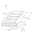
- Horizontal stripe fuel cell (hereinafter simply referred to as “fuel cell”) 100 includes a support substrate 102, a fuel electrode 103, an electrolyte layer 104, an air electrode 106, an interconnector 107, a current collector 108, and a barrier layer 13.
- the fuel cell 100 includes a cell 110. Constituent elements similar to those already described may be denoted by the same reference numerals and description thereof may be omitted. In FIG. 6, the current collector 108 is not shown for convenience of explanation.
- the fuel cell 100 includes a plurality of cells 110 disposed on a support substrate 102 and an interconnector 107 that electrically connects the cells 110.
- the cell 110 is a part that includes a fuel electrode 103 and an air electrode 106 corresponding to the fuel electrode 103.
- the cell 110 includes a fuel electrode 103, an electrolyte layer 104, and an air electrode 106 that are stacked in the thickness direction (y-axis direction) of the support substrate 102.
- the fuel electrode 103, the electrolyte layer 104, and the air electrode 106 constitute a power generation element part of the cell 110.
- the support substrate 102 is flat and has a shape that is long in one direction (z-axis direction).
- the support substrate 102 is a porous body having electrical insulation.
- the support substrate 102 may contain nickel. More specifically, the support substrate 102 may contain Ni—Y 2 O 3 (nickel-yttria) as a main component. Nickel may be contained as an oxide (NiO). During power generation, NiO may be reduced to Ni by hydrogen gas.
- a flow path 123 is provided inside the support substrate 102.
- the flow path 123 extends along the longitudinal direction (z-axis direction) of the support substrate 102.
- the fuel gas is caused to flow through the flow path 123, and the fuel gas is supplied to the fuel electrode 103 (to be described later) through the hole of the support substrate 102.
- the fuel electrode 103 is provided on the support substrate 102. On one support substrate 102, a plurality of fuel electrodes 103 are arranged in the longitudinal direction (z-axis direction) of the support substrate 102. That is, a gap is provided between adjacent fuel electrodes 103 in the longitudinal direction (z-axis direction) of the support substrate 102.
- the same composition as that of the fuel electrode 11 is applicable.
- the fuel electrode 103 may have a fuel electrode current collecting layer and a fuel electrode active layer.
- the anode current collecting layer is provided on the support substrate 102, and the anode active layer is provided on the anode current collecting layer so as not to overlap the interconnector 107.
- the fuel electrode 103 may have a fuel electrode current collecting layer and a fuel electrode active layer.
- the anode current collecting layer is provided on the support substrate 102, and the anode active layer is provided on the anode current collecting layer.
- the composition of the anode current collecting layer and the anode active layer is as described above.
- the electrolyte layer 104 is also called a solid electrolyte layer. As shown in FIG. 7, the electrolyte layer 104 is provided on the fuel electrode 103. In a region where the fuel electrode 103 is not provided on the support substrate 102, the electrolyte layer 104 may be provided on the support substrate 102.
- the electrolyte layer 104 has discontinuous portions in the longitudinal direction (z-axis direction) of the support substrate 102. That is, the plurality of electrolyte layers 104 are arranged at intervals in the z-axis direction. In other words, a single support substrate 102 is provided with a plurality of electrolyte layers 104 along the longitudinal direction (z-axis direction) of the support substrate 102.
- the electrolyte layers 104 adjacent in the z-axis direction are connected by the interconnector 107.
- the electrolyte layer 104 is provided continuously from a certain interconnector 107 to the interconnector 107 adjacent to the interconnector 107 in the longitudinal direction (z-axis direction) of the support substrate 102.
- the interconnector 107 and the electrolyte layer 104 have a dense structure as compared with the support substrate 102 and the fuel electrode 103. Therefore, the interconnector 107 and the electrolyte layer 104 have a structure that is continuous in the z-axis direction in the fuel cell 100, and thus function as a seal portion that separates air and fuel gas.
- composition of the electrolyte layer 104 the same composition as that of the electrolyte layer 15 described above can be applied.
- the configuration of the barrier layer 13 is as described in the vertical stripe fuel cell.
- the barrier layer 13 is provided between the electrolyte layer 104 and the air electrode 106.
- the air electrode 106 is disposed on the barrier layer 13 so as not to exceed the outer edge of the barrier layer 13.
- One air electrode 106 is laminated on one fuel electrode 103.
- one support substrate 102 is provided with a plurality of air electrodes 106 along the longitudinal direction (z-axis direction) of the support substrate 102.
- the air electrode 106 is similar to the air electrode 14 described above in the above 1. It is comprised by the electrode material demonstrated in the column.
- the air electrode 106 preferably contains additives (P, Cr, and B) in a predetermined weight ratio with respect to the entire electrode material, like the air electrode 14 of the vertical stripe fuel cell described above.
- the content of P is preferably 1 ppm or more and 50 ppm or less, and more preferably 1 ppm or more and 30 ppm or less by weight ratio to the raw material.
- the Cr content is preferably 1 ppm or more and 500 ppm or less, more preferably 1 ppm or more and 100 ppm or less, by weight ratio to the raw material.
- the content of B is preferably 1 ppm or more and 50 ppm or less, more preferably 1 ppm or more and 10 ppm or less by weight ratio to the raw material.
- the interconnector 107 is disposed so as to electrically connect the cells 110 as described above. In FIG. 7, the interconnector 107 is stacked on the fuel electrode 103.
- laminated includes a case where two elements are arranged so as to contact each other and a case where two elements are arranged so as not to contact each other but overlap in the y-axis direction.
- the interconnector 107 is disposed so as to connect the electrolyte layers 104 in the longitudinal direction (z-axis direction) of the support substrate 102. Thereby, the cells 110 adjacent in the longitudinal direction (z-axis direction) of the support substrate 102 are electrically connected.
- the interconnector 107 constitutes an electrode used for electrically connecting a plurality of cells 110 to each other. Specifically, the interconnector 107 illustrated in FIG. 7 functions as an electrode of the cell 110 disposed on the right side in FIG.
- the interconnector 107 constituting the electrode is the same as the above-described 1. It is comprised by the electrode material demonstrated in the column.
- the interconnector 107 contains a perovskite complex oxide as a main component.
- the perovskite complex oxide used for the interconnector 107 includes a chromite-based material such as lanthanum chromite (LaCrO 3 ).
- composition formula of lanthanum chromite can be expressed by the following general formula (1).
- Ln is at least one element selected from the group consisting of Y and lanthanoid
- A is at least one element selected from the group consisting of Ca, Sr and Ba
- B is , Ti, V, Mn, Fe, Co, Cu, Ni, Zn, Mg and Al, at least one element selected from the group consisting of 0.025 ⁇ x ⁇ 0.3, 0 ⁇ y ⁇ 0 .22, 0 ⁇ z ⁇ 0.15.
- Such lanthanum chromite is a material that can stably exist in both atmospheric and reducing atmospheres at the operating temperature of SOFC (600 to 1000 ° C), so it can be used as an interconnector material (electrode material) for SOFC cells including horizontal stripes. Preferably used.
- lanthanum chromite is known to be a hardly sinterable material, and in order to co-sinter with the support substrate 102, the fuel electrode 103, the electrolyte layer 104, etc. for application to the SOFC cell, a sintering aid is used. It is necessary to facilitate calcination by adding (CaO, SrO, etc.).
- the interconnector material (electrode material) to which the sintering aid is added also has high uniformity of composition distribution as described above. Specifically, at 10 spots in an arbitrary field of view of the interconnector material, when the atomic concentration of each element contained in the A site is obtained by EDS and the standard deviation value of the atomic concentration is obtained, It is preferable that the obtained standard deviation value is 10.3 or less.
- the interconnector 107 can be densified as a whole, it is possible to suppress the occurrence of a locally insufficiently fired region (pinhole) in the interconnector 107. As a result, the reliability of the interconnector 107 can be improved.
- the current collector 108 is disposed so as to electrically connect the interconnector 107 and the cell 110. Specifically, the current collector 108 is provided so as to continue from the air electrode 106 to the interconnector 107 included in the cell 110 adjacent to the cell 110 including the air electrode 106. The current collector 108 only needs to have conductivity.
- the air electrode 106 included in the cell 110 is electrically connected to the fuel electrode 103 of the adjacent cell 110 by the current collector 108 and the interconnector 107. That is, not only the interconnector 107 but also the current collector 108 contributes to the connection between the cells 110.
- each part of the fuel cell 100 can be set as follows.
- the thickness of the interconnector 107 10 to 100 ⁇ m
- the dimensions described for the vertical stripe fuel cell may be adopted. Needless to say, the technique disclosed here is not limited to these values.
- the air electrode material of the solid oxide fuel cell contains a complex oxide having a perovskite structure represented by the general formula ABO 3 , and the complex oxide is in a weight ratio with respect to the entire complex oxide. It is preferable to contain 1 ppm or more and 50 ppm or less of P, 1 ppm or more and 500 ppm or less of Cr, and 1 ppm or more and 50 ppm or less of B.
- the content of P contained in the composite oxide is more preferably 30 ppm or less in a weight ratio with respect to the whole composite oxide.
- the content of Cr contained in the composite oxide is more preferably 100 ppm or less by weight ratio with respect to the whole composite oxide.
- the content of B contained in the composite oxide is more preferably 10 ppm or less in terms of a weight ratio with respect to the entire composite oxide.
- the contents of P, Cr and B contained in the composite oxide are preferably 1 ppm or more.
- the electrode materials represented by the same general formula and having different numbers have different starting materials, firing conditions, and grinding conditions. Also, the table indicates whether each electrode material was synthesized by a solid phase method or a liquid phase method. Moreover, content of the additive (P, Cr, and B) contained in an electrode material is described in the table
- the average particle size of the obtained crushed material was 200 ⁇ m.
- the crushed material was used for the measurement of the composition distribution described later.
- the crushed material was pulverized by a ball mill device.
- the average particle diameter of the electrode material (powder) was measured with a laser diffraction / scattering particle size distribution analyzer (LA-700 manufactured by Horiba, Ltd.), and all were 1.0 ⁇ m or less.
- a paste was prepared using the obtained powder, and the paste was formed into a film by a screen printing method to form an air electrode (30 ⁇ m) on the barrier layer.
- the air electrode was baked on the barrier layer by being heated at 1000 ° C. for 2 hours.
- the SOFC cell was obtained by the above operation.
- no. 1-No. For each of the 10 samples, the concentrations of La and Sr at the A site were measured at 10 spots, the average value of La concentration and the standard deviation value of the concentration at each spot, and the average value of Sr concentration and the concentration at each spot. Standard deviation values were obtained. Similarly, for the Co and Fe at the B site, the concentration average value and the standard deviation value of the concentration at each spot were obtained. Furthermore, no. 1-No. For each of the ten samples, the maximum value of the standard deviation value for the atomic concentration of the element at the A site and the maximum value of the standard deviation value for the atomic concentration of the element at the B site were obtained.
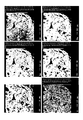
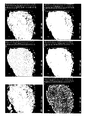
- FIGS. 1 and no. 7 shows SEM images and density mapping images in the same field of view.
- the portion where the atomic concentration is high is actually shown in red, and the portion where the atomic concentration is low is shown in blue.
- No. 11-No. 16 Regarding (La 0.8 Sr 0.2 ) FeO 3 11-No.
- Table 4 shows the measurement results of the concentration, the average value, and the standard deviation value of the 11 samples.
- no. 11-No. The maximum value of the standard deviation value of the atomic concentration of each element is shown for each of the 16 samples. For each sample, the maximum standard deviation value at the A site and the maximum standard deviation value at the B site are underlined.
- Table 6 No. 11-No.
- No. 17-No. 22 Regarding La (Ni 0.6 Fe 0.4 ) O 3 17-No.
- Table 7 shows the measurement results, the average values, and the standard deviation values of the concentrations of the 17 samples.
- no. 17-No. The maximum value of the standard deviation value of the atomic concentration of each element is shown for each of the 22 samples. For each sample, the maximum standard deviation value at the A site and the standard deviation value at the B site are underlined.
- Table 9 no. 17-No. 22 samples, the maximum standard deviation value at the A site and the maximum standard deviation value at the B site shown in Table 8, the voltage drop rate (deterioration rate) per 1000 hours, and the evaluation based on the voltage drop rate Results are shown.
- the standard deviation can be reduced by setting the contents of additives (P, Cr and B) contained in the air electrode material to 1 ppm ⁇ P ⁇ 50 ppm, 1 ppm ⁇ Cr ⁇ 500 ppm, and 1 ppm ⁇ B ⁇ 50 ppm. It was done.
- the content of the additives (P, Cr and B) contained in the air electrode material is 1 ppm ⁇ P ⁇ 30 ppm, 1 ppm ⁇ Cr ⁇ 100 ppm, 1 ppm ⁇ B ⁇ It was confirmed that 10 ppm is more preferable. The reason why such a result was obtained is considered to be that the addition of a trace amount of additive has the effect of strengthening the skeleton of the porous electrode.
- the relationship between the distribution of atoms and the deterioration of the air electrode can be considered as follows.
- the electrode material disclosed herein can be applied to various members that require electrical conductivity.
- this electrode material is applicable to the air electrode of a solid oxide fuel cell.
Landscapes
- Chemical & Material Sciences (AREA)
- Engineering & Computer Science (AREA)
- Materials Engineering (AREA)
- Chemical Kinetics & Catalysis (AREA)
- Ceramic Engineering (AREA)
- Organic Chemistry (AREA)
- Electrochemistry (AREA)
- General Chemical & Material Sciences (AREA)
- Manufacturing & Machinery (AREA)
- Structural Engineering (AREA)
- Sustainable Development (AREA)
- Sustainable Energy (AREA)
- Life Sciences & Earth Sciences (AREA)
- Inert Electrodes (AREA)
- Fuel Cell (AREA)
- Compounds Of Iron (AREA)
- Inorganic Compounds Of Heavy Metals (AREA)
Abstract
Description
しかしながら、燃料電池を用いた発電を繰り返すうちに、得られる電圧が低下することがある。本発明者らは、電圧の低下の原因の1つが空気極の劣化によるものであることを新たに見出した。
(課題を解決するための手段)
(発明の効果)
電極材料は、ペロブスカイト構造を有する複合酸化物を含む。電極材料は、複合酸化物以外の成分を含んでいてもよい。本実施形態に係る電極材料は、後述するように、固体酸化物型燃料電池の空気極やインターコネクタを構成する材料として好適に用いられる。
上記1.欄の電極材料の製造方法の例を以下に説明する。
・構成元素を含む原料を溶液に溶かすこと、
・その溶液から目的材料の前駆体を沈殿等によって得ること、及び
・さらに乾燥、焼成、及び粉砕を行うこと、
の工程によって、目的材料を得る手法である。
図1は、固相法を用いた電極材料の製造方法を説明するためのフロー図である。
図2は、液相法を用いた電極材料の製造方法を説明するためのフロー図である。
燃料電池の一例として、固体酸化物型燃料電池(Solid Oxide Fuel Cell:SOFC)を挙げる。特に以下では、主に、複数の燃料電池セルが積層されたセルスタック構造を有するSOFCについて説明する。
図3に示すように、燃料電池10は、燃料電池セル(単に「セル」と称される)1と、集電部材4とを備える。
セル1はセラミックスの薄板である。セル1の厚みは、例えば30μm~700μmであり、セル1の直径は、例えば5mm~50mmである。セル1は、図3に示すように、燃料極11、バリア層13、空気極14、および電解質層(固体電解質層)15を備える。
燃料極11の材料としては、例えば、公知の燃料電池セルにおいて燃料極の形成に用いられる材料が用いられる。燃料極11の材料として、より具体的には、NiO‐YSZ(酸化ニッケル‐イットリア安定化ジルコニア)及び/又はNiO‐Y2O3(酸化ニッケル‐イットリア)が挙げられる。燃料極11は、これらの材料を主成分として含むことができる。燃料極11は、アノードとして機能する。
バリア層13は、空気極14と燃料極11との間に設けられ、より具体的には、空気極14と電解質層15との間に設けられる。
空気極14は、上記1.欄で説明した電極材料によって構成されている。このような空気極14は、電極材料全体に対して所定重量比の添加物(P、Cr及びB)を含有していることが好ましい。この場合、Pの含有量は、原料に対する重量比で1ppm以上かつ50ppm以下であることが好ましく、1ppm以上かつ30ppm以下であることがより好ましい。また、Crの含有量は、原料に対する重量比で1ppm以上かつ500ppm以下であることが好ましく、1ppm以上かつ100ppm以下であることがより好ましい。また、Bの含有量は、原料に対する重量比で1ppm以上かつ50ppm以下であることが好ましく、1ppm以上かつ10ppm以下であることがより好ましい。
電解質層15は、バリア層13と燃料極11との間に設けられる。
集電部材4は、複数の導電接続部41を備える。
4-1.燃料極の形成
燃料極11は、圧粉成形によって形成可能である。すなわち、燃料極11は、燃料極11の材料が混合された粉末を型に入れ、圧縮して、圧粉体を成形することを含んでもよい。
燃料電池セルの製造方法は、圧粉成形によって形成された燃料極の成形体上に、電解質層を形成することを含む。
燃料電池セルの製造方法は、圧粉成形された燃料極及び電解質層を、共焼成(共焼結)することを含む。焼成の温度及び時間は、セルの材料等に応じて設定される。
上記4-3の焼成の前に、脱脂を行ってもよい。脱脂は、加熱によって実行される。温度及び時間などの条件は、セルの材料等に応じて設定される。
空気極は、例えば、燃料極、電解質層、及びバリア層の積層体(焼成後)上に、圧粉形成、印刷法等によって空気極の材料の層を形成した後、焼成することで形成される。具体的に、LSCFによって構成される電極材料を用いる場合には、印刷法を用いるのであれば、LSCFとバインダ、分散剤、分散媒を混合して作製されるペーストを積層体上に印刷して焼成(焼成温度900℃~1100℃、焼成時間1hr~10hr)すればよい。
燃料電池セルの構成に応じて、製造方法は他の工程をさらに含んでもよいし、上述の工程の内容が変更されてもよい。例えば、製造方法は、電解質層と空気極との間に反応防止層を設ける工程を含んでもよいし、2層構造の燃料極を形成する工程(基板を形成する工程及び燃料極活性層を形成する工程)を含んでもよい。
上述した燃料電池10は、積み重ねられた複数のセル1と、セル1間を電気的に接続する集電部材4とを備える。すなわち、燃料電池10は、縦縞型燃料電池である。ただし、ここに開示される技術は、横縞型燃料電池にも適用可能である。横縞型燃料電池について、以下に説明する。
支持基板102の厚みW2:1~10mm
支持基板102の長さW3:5~50cm
支持基板102の外面(支持基板102と燃料極との界面)から流路123までの距離W4:0.1~4mm
燃料極103の厚み :50~500μm
(燃料極103が、燃料極集電層及び燃料極活性層を有する場合:
燃料極集電層の厚み:50~500μm
燃料極活性層の厚み:5~30μm)
電解質層104の厚み :3~50μm
空気極106の厚み :10~100μm
インターコネクタ107の厚み:10~100μm
集電部108の厚み :50~500μm
固体酸化物型燃料電池セルの空気極材料は、一般式ABO3で表されるペロブスカイト構造を有する複合酸化物を含有しており、前記複合酸化物は、前記複合酸化物の全体に対する重量比で1ppm以上かつ50ppm以下のP、1ppm以上かつ500ppm以下のCr、および1ppm以上かつ50ppm以下のBを含む、ことが好ましい。
NiO-8YSZ燃料極基板(500μm)上に、NiO-8YSZ燃料極活性層(10μm)、8YSZ電解質層(3μm)、GDCバリア層(3μm)を積層した後、1400℃で2hrの条件で、共焼成した。
B-1.組成分布の測定
電極材料の解砕物について、EPMAにより各元素の原子濃度分布を測定した。具体的には、日本電子株式会社の電界放射型電子プローブマイクロアナライザー(型番:JXA-8500F)を用いて測定を行った。次に、EDSにより任意の視野において、SEM像で確認できる空洞になっていない部分の10スポットで、Aサイトの各元素、Bサイトの各元素の酸化物としての原子濃度(mol%)を測定した。具体的には、ZEISS社(ドイツ)の電界放射型走査電子顕微鏡(型番:ULTRA55)を用いて測定を行った。
作製したSOFCセルを用いて連続発電を実施した。発電条件は温度:750℃、電流密度:0.3A/cm2であり、この条件による1000時間あたりの電圧降下率(劣化率)を算出した。劣化率が1%以下のものを“良好”と判定した。
C-1.No.1~No.10:(La0.6Sr0.4)(Co0.2Fe0.8)O3について
No.1~No.10の試料のうち、一例としてNo.1の試料における濃度の測定結果、平均値及び標準偏差値の算出結果を表1に示す。表2には、No.1~No.10の各試料について、各元素の原子濃度の標準偏差値の最大値を示す。各試料について、Aサイトにおける標準偏差値の最大値及びBサイトにおける標準偏差値の最大値に、下線を付す。表3には、No.1~No.10の試料について、表2に示したAサイトにおける標準偏差値の最大値及びBサイトにおける標準偏差値の最大値と、1000時間当たりの電圧降下率(劣化率)と、電圧降下率に基づく評価結果と、を示す。


No.11~No.16の試料のうち、一例としてNo.11の試料における濃度の測定結果、平均値及び標準偏差値の算出結果を表4に示す。表5には、No.11~No.16の各試料について、各元素の原子濃度の標準偏差値の最大値を示す。各試料について、Aサイトにおける標準偏差値の最大値及びBサイトにおける標準偏差値の最大値に、下線を付す。表6には、No.11~No.16の試料について、表5に示したAサイトにおける標準偏差値の最大値及びBサイトにおける標準偏差値の最大値と、1000時間当たりの電圧降下率(劣化率)と、電圧降下率に基づく評価結果と、を示す。


No.17~No.22の試料のうち、一例としてNo.17の試料における濃度の測定結果、平均値及び標準偏差値の算出結果を表7に示す。表8には、No.17~No.22の各試料について、各元素の原子濃度の標準偏差値の最大値を示す。各試料について、Aサイトにおける標準偏差値の最大値及びBサイトにおける標準偏差値の最大値に、下線を付す。表9には、No.17~No.22の試料について、表8に示したAサイトにおける標準偏差値の最大値及びBサイトにおける標準偏差値の最大値と、1000時間当たりの電圧降下率(劣化率)と、電圧降下率に基づく評価結果と、を示す。


次に、No.23~No.28の試料における添加物(P、Cr及びB)の濃度と1000時間当たりの電圧降下率(劣化率)の測定結果を表10に示す。

表10に示すように、No.28の試料では劣化率を小さく抑えることができなかった。従って、電極材料にはP、Cr及びBのすべてを1ppm以上添加されていることが好ましいことが判った。また、No.23の試料でも劣化率を小さく抑えることができなかった。従って、電極材料におけるPの含有量が50ppm以下であり、Crの含有量が500ppm以下であり、かつ、Bの含有量が50ppm以下であることが好ましいことが確認された。さらに、No.24,25とNo.26,27との比較から、電極材料におけるPの含有量が30ppm以下であり、Crの含有量が100ppm以下であり、かつ、Bの含有量が10ppm以下であることがさらに好ましいことが確認された。
以上の結果から、原子の分布が比較的均一である(標準偏差が小さい)ことで、空気極の劣化が抑制されると考えられる。
10 燃料電池
11 燃料極
13 バリア層
14 空気極
15 電解質層
4 集電部材
41 導電接続部
Claims (10)
- 一般式ABO3で表されるペロブスカイト構造を有する複合酸化物によって構成される空気極材料であって、
1つの視野内の10スポットにおいてエネルギー分散型X線分光法により測定されたAサイト内の各元素の原子濃度の標準偏差値が10.3以下である
固体酸化物型燃料電池セルの空気極材料。 - 前記Aサイトには、La及びSrの少なくとも一方の原子が含まれる
請求項1に記載の固体酸化物型燃料電池セルの空気極材料。 - 前記複合酸化物は、(La,Sr)(Co,Fe)O3、(La,Sr)FeO3、(La,Sr)CoO3、又はLa(Ni,Fe)O3である
請求項2に記載の固体酸化物型燃料電池セルの空気極材料。 - 前記1つの視野は、電子顕微鏡において100倍~5000倍の倍率で観察される範囲である
請求項1~3のいずれかに記載の固体酸化物型燃料電池セルの空気極材料。 - 前記10スポットそれぞれのサイズは、1μm以下である
請求項1~4のいずれかに記載の固体酸化物型燃料電池セルの空気極材料。 - 前記10スポットの位置は、前記1つの視野内における前記原子濃度の分布に基づいて設定される10段階の濃度レベルに応じて、前記1つの視野内から選択される
請求項1~5のいずれかに記載の固体酸化物型燃料電池セルの空気極材料。 - 前記10段階の濃度レベルは、前記原子濃度の分布の全範囲に渡って設定される
請求項6に記載の固体酸化物型燃料電池セルの空気極材料。 - 請求項1~7のいずれかに記載の空気極材料からなる空気極と、
燃料極と、
前記空気極と前記燃料極との間に配置される固体電解質層と、
を備える
固体酸化物型燃料電池セル。 - 一般式ABO3で表されるペロブスカイト構造を有する複合酸化物によって構成されるインターコネクタ材料であって、
1つの視野内の10スポットにおいてエネルギー分散型X線分光法により測定されたAサイト内の各元素の原子濃度の標準偏差値が10.3以下である
固体酸化物型燃料電池セルのインターコネクタ材料。 - ガス流路を内部に有し、電気的絶縁性の多孔質支持基板と、
前記多孔質支持基板上に順次積層された燃料極と固体電解質層と空気極とによって構成される発電素子部と、
請求項9に記載のインターコネクタ材料によって構成されており、前記発電素子部に接続されるインターコネクタと、
を備える
固体酸化物型燃料電池セル。
Priority Applications (10)
| Application Number | Priority Date | Filing Date | Title |
|---|---|---|---|
| JP2012542715A JP5140787B1 (ja) | 2011-12-19 | 2012-09-14 | 空気極材料、インターコネクタ材料及び固体酸化物型燃料電池セル |
| EP12859479.3A EP2750227B1 (en) | 2011-12-19 | 2012-09-14 | Air electrode material and solid oxide fuel cell |
| PCT/JP2012/082357 WO2013094516A1 (ja) | 2011-12-19 | 2012-12-13 | 固体酸化物型燃料電池セル |
| JP2013519673A JP5395311B1 (ja) | 2011-12-19 | 2012-12-13 | 固体酸化物型燃料電池セル |
| EP12860994.8A EP2797147B1 (en) | 2011-12-19 | 2012-12-13 | Solid oxide fuel cell |
| EP17185353.4A EP3300149B1 (en) | 2011-12-19 | 2012-12-13 | Solid oxide fuel cell |
| JP2013092900A JP5389287B2 (ja) | 2011-12-19 | 2013-04-25 | 固体酸化物型燃料電池セル |
| JP2013092901A JP5326061B2 (ja) | 2011-12-19 | 2013-04-25 | 固体酸化物型燃料電池セル |
| US14/304,434 US10056620B2 (en) | 2011-12-19 | 2014-06-13 | Solid oxide fuel cell |
| US16/037,366 US10862134B2 (en) | 2011-12-19 | 2018-07-17 | Solid oxide fuel cell |
Applications Claiming Priority (4)
| Application Number | Priority Date | Filing Date | Title |
|---|---|---|---|
| JP2011277507 | 2011-12-19 | ||
| JP2011-277507 | 2011-12-19 | ||
| JP2012033102 | 2012-02-17 | ||
| JP2012-033102 | 2012-02-17 |
Publications (1)
| Publication Number | Publication Date |
|---|---|
| WO2013094260A1 true WO2013094260A1 (ja) | 2013-06-27 |
Family
ID=48189429
Family Applications (2)
| Application Number | Title | Priority Date | Filing Date |
|---|---|---|---|
| PCT/JP2012/073682 WO2013094260A1 (ja) | 2011-12-19 | 2012-09-14 | 空気極材料、インターコネクタ材料及び固体酸化物型燃料電池セル |
| PCT/JP2012/082357 WO2013094516A1 (ja) | 2011-12-19 | 2012-12-13 | 固体酸化物型燃料電池セル |
Family Applications After (1)
| Application Number | Title | Priority Date | Filing Date |
|---|---|---|---|
| PCT/JP2012/082357 WO2013094516A1 (ja) | 2011-12-19 | 2012-12-13 | 固体酸化物型燃料電池セル |
Country Status (4)
| Country | Link |
|---|---|
| US (3) | US9520597B2 (ja) |
| EP (3) | EP2750227B1 (ja) |
| JP (5) | JP5178956B1 (ja) |
| WO (2) | WO2013094260A1 (ja) |
Cited By (3)
| Publication number | Priority date | Publication date | Assignee | Title |
|---|---|---|---|---|
| JP5663694B1 (ja) * | 2013-08-23 | 2015-02-04 | 日本碍子株式会社 | 空気極材料及び固体酸化物型燃料電池 |
| JP2018142419A (ja) * | 2017-02-27 | 2018-09-13 | アイシン精機株式会社 | 固体酸化物形燃料電池セル |
| JP2019102125A (ja) * | 2017-11-28 | 2019-06-24 | 日本碍子株式会社 | 電気化学セル |
Families Citing this family (18)
| Publication number | Priority date | Publication date | Assignee | Title |
|---|---|---|---|---|
| US20120321994A1 (en) * | 2011-06-15 | 2012-12-20 | Zhien Liu | Fuel cell system with interconnect |
| WO2013094260A1 (ja) * | 2011-12-19 | 2013-06-27 | 日本碍子株式会社 | 空気極材料、インターコネクタ材料及び固体酸化物型燃料電池セル |
| JP6181940B2 (ja) * | 2013-02-27 | 2017-08-16 | Dowaエレクトロニクス株式会社 | ペロブスカイト型複合酸化物およびその製造方法 |
| JP6181941B2 (ja) * | 2013-02-27 | 2017-08-16 | Dowaエレクトロニクス株式会社 | ペロブスカイト型複合酸化物の前駆体粉末およびその製造方法 |
| KR102091455B1 (ko) * | 2014-02-17 | 2020-03-23 | 울산과학기술원 | 이중층 페로브스카이트 구조를 가지는 이중 모드 전지 |
| JP6441055B2 (ja) * | 2014-12-10 | 2018-12-19 | 三菱日立パワーシステムズ株式会社 | 固体酸化物形燃料電池及び固体酸化物形燃料電池の製造方法 |
| JP5981066B1 (ja) * | 2015-07-01 | 2016-08-31 | 日本碍子株式会社 | 燃料電池 |
| CN107710478B (zh) * | 2015-07-07 | 2020-08-25 | 日本碍子株式会社 | 燃料电池 |
| JP6317711B2 (ja) * | 2015-08-04 | 2018-04-25 | 日本特殊陶業株式会社 | 固体酸化物形電気化学セル、固体酸化物形燃料電池、及び高温水蒸気電気分解装置 |
| CN109478648B (zh) * | 2016-07-27 | 2021-10-22 | 日本碍子株式会社 | 燃料电池 |
| JP6712280B2 (ja) * | 2016-08-08 | 2020-06-17 | 森村Sofcテクノロジー株式会社 | 電気化学反応単セルおよび電気化学反応セルスタック |
| WO2020066301A1 (ja) * | 2018-09-27 | 2020-04-02 | 堺化学工業株式会社 | 固体酸化物形燃料電池空気極用の粉体およびその製造方法 |
| WO2020158339A1 (ja) * | 2019-01-30 | 2020-08-06 | 日本碍子株式会社 | 電気化学セル |
| DE112020000010T5 (de) * | 2019-01-30 | 2021-01-21 | Ngk Insulators, Ltd. | Elektrochemische zelle |
| WO2021162975A1 (en) * | 2020-02-11 | 2021-08-19 | Phillips 66 Company | Solid oxide fuel cell cathode materials |
| JP7082637B2 (ja) * | 2020-04-02 | 2022-06-08 | 森村Sofcテクノロジー株式会社 | 電気化学反応セルスタック |
| CN111584911B (zh) * | 2020-05-11 | 2022-11-01 | 合肥学院 | 一种Fe3O4-BCFN中温复合固体电解质及其制备方法 |
| CN114054032B (zh) * | 2021-11-23 | 2023-11-07 | 东莞理工学院 | 一种锶系钙钛矿催化阴极的制备方法及其应用 |
Citations (8)
| Publication number | Priority date | Publication date | Assignee | Title |
|---|---|---|---|---|
| JPH0992302A (ja) * | 1995-09-28 | 1997-04-04 | Kyocera Corp | 円筒型燃料電池セルおよびその製造方法 |
| JP2001297783A (ja) * | 2000-04-11 | 2001-10-26 | Toto Ltd | 固体電解質型燃料電池 |
| JP2003308846A (ja) * | 2002-02-13 | 2003-10-31 | Toyota Motor Corp | ペロブスカイト型酸化物及び燃料電池用空気極 |
| JP2004265746A (ja) * | 2003-03-03 | 2004-09-24 | Toto Ltd | 固体酸化物形燃料電池 |
| JP2004273143A (ja) * | 2003-03-05 | 2004-09-30 | Japan Fine Ceramics Center | 固体酸化物形燃料電池及び固体酸化物形燃料電池の空気極用材料 |
| JP2006032132A (ja) | 2004-07-16 | 2006-02-02 | Hosokawa Funtai Gijutsu Kenkyusho:Kk | 固体電解質型燃料電池の空気極原料粉体、空気極及び固体電解質型燃料電池 |
| WO2007061043A1 (ja) * | 2005-11-25 | 2007-05-31 | Nippon Telegraph And Telephone Corporation | 固体酸化物形燃料電池 |
| JP2009048917A (ja) * | 2007-08-21 | 2009-03-05 | Tokyo Gas Co Ltd | 横縞型固体酸化物形燃料電池スタック及びその作製方法 |
Family Cites Families (17)
| Publication number | Priority date | Publication date | Assignee | Title |
|---|---|---|---|---|
| JPS5140787B2 (ja) | 1971-09-16 | 1976-11-05 | ||
| JPH06122571A (ja) * | 1992-10-14 | 1994-05-06 | Ngk Insulators Ltd | 多孔質焼結体及び固体電解質型燃料電池 |
| JP3359412B2 (ja) * | 1994-03-11 | 2002-12-24 | 京セラ株式会社 | 固体電解質型燃料電池セル |
| US5916700A (en) * | 1998-01-23 | 1999-06-29 | Siemens Westinghouse Power Corporation | Lanthanum manganite-based air electrode for solid oxide fuel cells |
| US6358567B2 (en) * | 1998-12-23 | 2002-03-19 | The Regents Of The University Of California | Colloidal spray method for low cost thin coating deposition |
| JP3456436B2 (ja) | 1999-02-24 | 2003-10-14 | 三菱マテリアル株式会社 | 固体酸化物型燃料電池 |
| US20020127455A1 (en) * | 2001-03-08 | 2002-09-12 | The Regents Of The University Of California | Ceria-based solid oxide fuel cells |
| US20080124598A1 (en) * | 2006-11-29 | 2008-05-29 | Monika Backhaus-Ricoult | Activation of solid oxide fuel cell electrode surfaces |
| DK2031677T3 (da) * | 2007-08-31 | 2011-12-12 | Univ Denmark Tech Dtu | Fjernelse af forureningsfaser fra elektrokemiske indretninger |
| JP2011190148A (ja) | 2010-03-15 | 2011-09-29 | Sumitomo Osaka Cement Co Ltd | 複合セラミックス粉体及びその製造方法並びに固体酸化物形燃料電池 |
| JP2012043774A (ja) | 2010-07-21 | 2012-03-01 | Ngk Insulators Ltd | 電極材料及びそれを含む固体酸化物型燃料電池セル |
| JP5543297B2 (ja) * | 2010-08-25 | 2014-07-09 | Agcセイミケミカル株式会社 | 固体酸化物型燃料電池用空気極材料粉末及びその製造方法 |
| JP5520210B2 (ja) | 2010-12-27 | 2014-06-11 | Agcセイミケミカル株式会社 | 固体酸化物型燃料電池用空気極材料粉末及びその製造方法 |
| JP5097867B1 (ja) * | 2011-10-14 | 2012-12-12 | 日本碍子株式会社 | 燃料電池セル |
| JP5242840B1 (ja) * | 2011-10-14 | 2013-07-24 | 日本碍子株式会社 | 燃料電池セル |
| JP5140787B1 (ja) | 2011-12-19 | 2013-02-13 | 日本碍子株式会社 | 空気極材料、インターコネクタ材料及び固体酸化物型燃料電池セル |
| WO2013094260A1 (ja) * | 2011-12-19 | 2013-06-27 | 日本碍子株式会社 | 空気極材料、インターコネクタ材料及び固体酸化物型燃料電池セル |
-
2012
- 2012-09-14 WO PCT/JP2012/073682 patent/WO2013094260A1/ja active Application Filing
- 2012-09-14 EP EP12859479.3A patent/EP2750227B1/en active Active
- 2012-09-14 US US13/616,905 patent/US9520597B2/en active Active
- 2012-11-20 JP JP2012254563A patent/JP5178956B1/ja active Active
- 2012-11-20 JP JP2012254564A patent/JP5178957B1/ja active Active
- 2012-12-13 JP JP2013519673A patent/JP5395311B1/ja active Active
- 2012-12-13 WO PCT/JP2012/082357 patent/WO2013094516A1/ja active Application Filing
- 2012-12-13 EP EP12860994.8A patent/EP2797147B1/en active Active
- 2012-12-13 EP EP17185353.4A patent/EP3300149B1/en active Active
-
2013
- 2013-04-25 JP JP2013092900A patent/JP5389287B2/ja active Active
- 2013-04-25 JP JP2013092901A patent/JP5326061B2/ja active Active
-
2014
- 2014-06-13 US US14/304,434 patent/US10056620B2/en active Active
-
2018
- 2018-07-17 US US16/037,366 patent/US10862134B2/en active Active
Patent Citations (8)
| Publication number | Priority date | Publication date | Assignee | Title |
|---|---|---|---|---|
| JPH0992302A (ja) * | 1995-09-28 | 1997-04-04 | Kyocera Corp | 円筒型燃料電池セルおよびその製造方法 |
| JP2001297783A (ja) * | 2000-04-11 | 2001-10-26 | Toto Ltd | 固体電解質型燃料電池 |
| JP2003308846A (ja) * | 2002-02-13 | 2003-10-31 | Toyota Motor Corp | ペロブスカイト型酸化物及び燃料電池用空気極 |
| JP2004265746A (ja) * | 2003-03-03 | 2004-09-24 | Toto Ltd | 固体酸化物形燃料電池 |
| JP2004273143A (ja) * | 2003-03-05 | 2004-09-30 | Japan Fine Ceramics Center | 固体酸化物形燃料電池及び固体酸化物形燃料電池の空気極用材料 |
| JP2006032132A (ja) | 2004-07-16 | 2006-02-02 | Hosokawa Funtai Gijutsu Kenkyusho:Kk | 固体電解質型燃料電池の空気極原料粉体、空気極及び固体電解質型燃料電池 |
| WO2007061043A1 (ja) * | 2005-11-25 | 2007-05-31 | Nippon Telegraph And Telephone Corporation | 固体酸化物形燃料電池 |
| JP2009048917A (ja) * | 2007-08-21 | 2009-03-05 | Tokyo Gas Co Ltd | 横縞型固体酸化物形燃料電池スタック及びその作製方法 |
Non-Patent Citations (1)
| Title |
|---|
| See also references of EP2750227A4 |
Cited By (4)
| Publication number | Priority date | Publication date | Assignee | Title |
|---|---|---|---|---|
| JP5663694B1 (ja) * | 2013-08-23 | 2015-02-04 | 日本碍子株式会社 | 空気極材料及び固体酸化物型燃料電池 |
| JP2015062172A (ja) * | 2013-08-23 | 2015-04-02 | 日本碍子株式会社 | 空気極材料及び固体酸化物型燃料電池 |
| JP2018142419A (ja) * | 2017-02-27 | 2018-09-13 | アイシン精機株式会社 | 固体酸化物形燃料電池セル |
| JP2019102125A (ja) * | 2017-11-28 | 2019-06-24 | 日本碍子株式会社 | 電気化学セル |
Also Published As
| Publication number | Publication date |
|---|---|
| JP5326061B2 (ja) | 2013-10-30 |
| JP5178956B1 (ja) | 2013-04-10 |
| US20140315116A1 (en) | 2014-10-23 |
| EP2797147A1 (en) | 2014-10-29 |
| JP5178957B1 (ja) | 2013-04-10 |
| JP2013191570A (ja) | 2013-09-26 |
| US10056620B2 (en) | 2018-08-21 |
| EP2797147A4 (en) | 2015-12-09 |
| EP3300149B1 (en) | 2019-05-22 |
| EP2750227A4 (en) | 2015-06-24 |
| EP2750227B1 (en) | 2016-11-30 |
| EP3300149A1 (en) | 2018-03-28 |
| WO2013094516A1 (ja) | 2013-06-27 |
| JPWO2013094516A1 (ja) | 2015-04-27 |
| EP2797147B1 (en) | 2018-07-18 |
| JP5395311B1 (ja) | 2014-01-22 |
| EP2750227A1 (en) | 2014-07-02 |
| JP2013191535A (ja) | 2013-09-26 |
| JP2013191534A (ja) | 2013-09-26 |
| JP5389287B2 (ja) | 2014-01-15 |
| US9520597B2 (en) | 2016-12-13 |
| US20130244132A1 (en) | 2013-09-19 |
| JP2013191569A (ja) | 2013-09-26 |
| US10862134B2 (en) | 2020-12-08 |
| US20180323440A1 (en) | 2018-11-08 |
Similar Documents
| Publication | Publication Date | Title |
|---|---|---|
| JP5178956B1 (ja) | 空気極材料及び固体酸化物型燃料電池セル | |
| JP2012043774A (ja) | 電極材料及びそれを含む固体酸化物型燃料電池セル | |
| CN105409041B (zh) | 固体氧化物燃料电池及其制造方法 | |
| JP4928642B1 (ja) | 固体酸化物型燃料電池 | |
| JP5140787B1 (ja) | 空気極材料、インターコネクタ材料及び固体酸化物型燃料電池セル | |
| JP4989774B2 (ja) | 電極材料及びそれを含む固体酸化物型燃料電池セル | |
| JP6042320B2 (ja) | 電極材料とその利用 | |
| JP5502180B2 (ja) | 固体酸化物型燃料電池 | |
| JP5117605B2 (ja) | 電極材料及びそれを含む固体酸化物型燃料電池セル | |
| KR20190028340A (ko) | 고체산화물 연료 전지 및 이를 포함하는 전지 모듈 | |
| JP2012099322A (ja) | 固体酸化物型燃料電池 | |
| JP6188569B2 (ja) | 電極材料とその利用 | |
| JP5555682B2 (ja) | 固体酸化物型燃料電池 | |
| JP5486749B2 (ja) | 燃料電池セル | |
| KR20200105173A (ko) | 고체산화물 연료전지용 공기극, 이를 포함하는 고체산화물 연료 전지, 이를 포함하는 전지모듈 및 고체산화물 연료전지의 제조방법 | |
| KR20200099784A (ko) | 고체산화물 연료전지 연결재용 조성물, 이를 이용한 고체산화물 연료전지 연결재의 제조방법 및 이를 포함하는 고체산화물 연료전지 |
Legal Events
| Date | Code | Title | Description |
|---|---|---|---|
| ENP | Entry into the national phase |
Ref document number: 2012542715 Country of ref document: JP Kind code of ref document: A |
|
| 121 | Ep: the epo has been informed by wipo that ep was designated in this application |
Ref document number: 12859479 Country of ref document: EP Kind code of ref document: A1 |
|
| REEP | Request for entry into the european phase |
Ref document number: 2012859479 Country of ref document: EP |
|
| WWE | Wipo information: entry into national phase |
Ref document number: 2012859479 Country of ref document: EP |
|
| NENP | Non-entry into the national phase |
Ref country code: DE |