WO2013084340A1 - 現像剤収容室、現像装置、プロセスカートリッジ、画像形成装置 - Google Patents
現像剤収容室、現像装置、プロセスカートリッジ、画像形成装置 Download PDFInfo
- Publication number
- WO2013084340A1 WO2013084340A1 PCT/JP2011/078436 JP2011078436W WO2013084340A1 WO 2013084340 A1 WO2013084340 A1 WO 2013084340A1 JP 2011078436 W JP2011078436 W JP 2011078436W WO 2013084340 A1 WO2013084340 A1 WO 2013084340A1
- Authority
- WO
- WIPO (PCT)
- Prior art keywords
- developer
- chamber
- developing
- connecting portion
- shaft member
- Prior art date
- Legal status (The legal status is an assumption and is not a legal conclusion. Google has not performed a legal analysis and makes no representation as to the accuracy of the status listed.)
- Ceased
Links
Images









Classifications
-
- G—PHYSICS
- G03—PHOTOGRAPHY; CINEMATOGRAPHY; ANALOGOUS TECHNIQUES USING WAVES OTHER THAN OPTICAL WAVES; ELECTROGRAPHY; HOLOGRAPHY
- G03G—ELECTROGRAPHY; ELECTROPHOTOGRAPHY; MAGNETOGRAPHY
- G03G21/00—Arrangements not provided for by groups G03G13/00 - G03G19/00, e.g. cleaning, elimination of residual charge
- G03G21/16—Mechanical means for facilitating the maintenance of the apparatus, e.g. modular arrangements
- G03G21/18—Mechanical means for facilitating the maintenance of the apparatus, e.g. modular arrangements using a processing cartridge, whereby the process cartridge comprises at least two image processing means in a single unit
-
- G—PHYSICS
- G03—PHOTOGRAPHY; CINEMATOGRAPHY; ANALOGOUS TECHNIQUES USING WAVES OTHER THAN OPTICAL WAVES; ELECTROGRAPHY; HOLOGRAPHY
- G03G—ELECTROGRAPHY; ELECTROPHOTOGRAPHY; MAGNETOGRAPHY
- G03G15/00—Apparatus for electrographic processes using a charge pattern
- G03G15/06—Apparatus for electrographic processes using a charge pattern for developing
- G03G15/08—Apparatus for electrographic processes using a charge pattern for developing using a solid developer, e.g. powder developer
- G03G15/0822—Arrangements for preparing, mixing, supplying or dispensing developer
- G03G15/0877—Arrangements for metering and dispensing developer from a developer cartridge into the development unit
-
- G—PHYSICS
- G03—PHOTOGRAPHY; CINEMATOGRAPHY; ANALOGOUS TECHNIQUES USING WAVES OTHER THAN OPTICAL WAVES; ELECTROGRAPHY; HOLOGRAPHY
- G03G—ELECTROGRAPHY; ELECTROPHOTOGRAPHY; MAGNETOGRAPHY
- G03G21/00—Arrangements not provided for by groups G03G13/00 - G03G19/00, e.g. cleaning, elimination of residual charge
- G03G21/16—Mechanical means for facilitating the maintenance of the apparatus, e.g. modular arrangements
- G03G21/18—Mechanical means for facilitating the maintenance of the apparatus, e.g. modular arrangements using a processing cartridge, whereby the process cartridge comprises at least two image processing means in a single unit
- G03G21/1803—Arrangements or disposition of the complete process cartridge or parts thereof
- G03G21/1814—Details of parts of process cartridge, e.g. for charging, transfer, cleaning, developing
Definitions
- the present invention relates to an image forming apparatus, a developer storage chamber used in the image forming apparatus, a developing apparatus, and a process cartridge.
- the image forming apparatus forms an image on a recording medium.
- an electrophotographic copying machine using an electrophotographic image forming process an electrophotographic printer (LED printer, laser beam printer, etc.), an electrophotographic facsimile machine, and the like are included.
- Developer storage chamber is for storing developer inside.
- the developing device has a developer carrier and a developer storage chamber.
- the process cartridge is a cartridge in which an image carrier and a developer carrier are integrally formed, and the cartridge can be attached to and detached from the image forming apparatus main body.
- a process cartridge is provided with a developing device for developing an electrostatic latent image formed on an image carrier with a developer.
- This developing device has a developing chamber in which a developer carrying member is disposed, and a developer accommodating chamber in which the developer is accommodated.
- An opening is provided between the developing chamber and the developer accommodating chamber so that the developer can enter and exit, and the developer is supplied from the developer accommodating chamber to the developer accommodating chamber by the stirring means. ing.
- the stirring means includes a shaft member rotatably provided in the developer storage chamber and an elastic sheet fixed to the shaft member.
- the leading end of the elastic sheet enters the developing chamber from the developer accommodating chamber.
- the strength of the developing device is lowered by providing the developing device with a developing opening which is a passage for the developer. Therefore, there is a method of reinforcing the developing device by partially connecting two opposing sides extending in the axial direction of the developer carrier among the end portions of the developing opening by connecting portions such as ribs.
- the present invention has been made to solve the above-described problems in the prior art.
- the purpose is to satisfactorily convey the toner from the developer accommodating chamber to the developing chamber even in the case where a connecting portion is provided at the opening communicating the developer accommodating chamber and the developing chamber in order to reinforce the apparatus.
- a typical configuration of the present invention for achieving the above object is as follows.
- the sheet member is an intrusion portion formed by a first incision extending from a free end of the sheet member and intersecting the connecting portion when viewed from a direction orthogonal to the longitudinal direction, and the developer It has an intrusion portion that enters from the inside of the storage chamber to the outside and overlaps with the connection portion when viewed from a direction orthogonal to the longitudinal direction of the shaft member.
- Another configuration of the present invention is as follows.
- a developing device for developing a latent image formed on an image carrier A developer carrying member carrying the developer; A developing chamber in which the developer carrying member is disposed; A developer storage chamber for storing the developer therein; An opening communicating the developing chamber and the developer storage chamber; A shaft member rotatably supported in the developer storage chamber; A sheet member that is fixed to the shaft member and conveys the developer from the agent storage chamber to the developing chamber when the shaft member rotates; A connecting portion that connects one end and the other end of the opening in a direction perpendicular to the longitudinal direction of the shaft member; With The sheet member is an intrusion portion formed by a first incision extending from a free end of the sheet member and intersecting the connecting portion when viewed from a direction orthogonal to the longitudinal direction, and the developer It has an intrusion portion that enters the developing chamber from the storage chamber and overlaps with the connecting portion when viewed from a direction orthogonal to the longitudinal direction of the shaft member.
- Another configuration of the present invention is as follows.
- the sheet member is an intrusion portion formed by a first incision extending from a free end of the sheet member and intersecting the connecting portion when viewed from a direction orthogonal to the longitudinal direction, and the developer It has an intrusion portion that enters the developing chamber from the storage chamber and overlaps with the connecting portion when viewed from a direction orthogonal to
- Another configuration of the present invention is as follows.
- Conveying means for conveying the recording medium;
- An image carrier on which a latent image is formed;
- a developer carrying member carrying a developer for developing the latent image;
- a developing chamber in which the developer carrying member is disposed;
- a developer storage chamber for storing the developer therein;
- An opening communicating the developing chamber and the developer storage chamber;
- a shaft member rotatably supported in the developer storage chamber;
- a sheet member that is fixed to the shaft member and conveys the developer from the agent storage chamber to the developing chamber when the shaft member rotates;
- a connecting portion that connects one end and the other end of the opening in a direction perpendicular to the longitudinal direction of the shaft member;
- the sheet member is an intrusion portion formed by a first incision extending from a free end of the sheet member and intersecting the connecting portion when viewed from a direction orthogonal to the longitudinal direction, and the developer It has an intrusion portion that enters the developing chamber from the storage chamber and overlaps with the
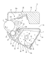
- FIG. 1 is an overall schematic explanatory diagram of an image forming apparatus according to a first embodiment. It is a longitudinal cross-sectional explanatory drawing of the process cartridge which concerns on 1st Embodiment.
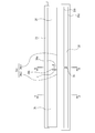
- FIG. 3 is a schematic explanatory diagram of a development opening and an elastic sheet according to the first embodiment. It is a behavior explanation longitudinal section of the 1st conveyance part concerning a 1st embodiment. It is a behavior explanation longitudinal section of the 1st conveyance part concerning a 1st embodiment. It is a behavior explanation longitudinal section of the 1st conveyance part concerning a 1st embodiment. It is a behavior explanation longitudinal section of the 1st conveyance part concerning a 1st embodiment.
- the longitudinal direction of the process cartridge is simply referred to as the longitudinal direction.
- This longitudinal direction coincides with the longitudinal direction (axial direction) of the image carrier (photosensitive drum).
- the short direction of the process cartridge is simply referred to as the short direction.
- the short direction is a direction orthogonal to the rotation axis of the image carrier and coincides with the conveyance direction of the recording medium.
- “upper” means the upper side when the process cartridge is mounted on the image forming apparatus main body, and “lower” means the lower side in the same state.
- a laser beam printer 1 shown in FIG. 2 is an image forming apparatus that forms an image with a developer on a recording medium P (for example, recording paper, an OHP sheet, cloth, or the like) by an electrophotographic image forming process.
- a laser printer (hereinafter referred to as an image forming apparatus) 1 forms an image according to image information from an external device such as a personal computer that is communicably connected to the image forming apparatus main body 1a.
- the surface of the drum-shaped image carrier (hereinafter referred to as “photosensitive drum”) 2 is uniformly charged by a charging roller 3 serving as a charging unit.
- the photosensitive drum 2 is irradiated with laser light L corresponding to the image information from the optical means (exposure means) 4 to form an electrostatic latent image corresponding to the image information on the photosensitive drum 2.
- the electrostatic latent image formed on the photosensitive drum 2 formed here is developed with toner as a developer by a developing unit described later, thereby forming a toner image.
- the recording medium P set in the feeding cassette 6 is separated and fed one by one by the pickup roller 7 and the pressure contact member 9 in pressure contact therewith. Then, the recording medium P is conveyed along the conveyance guide 8 to a transfer roller 10 as a transfer unit. Next, the recording medium P passes through a transfer nip formed by the photosensitive drum 2 and the transfer roller 10 to which a constant voltage is applied. At this time, the toner image formed on the photosensitive drum 2 is transferred to the recording medium P.
- the recording medium P that has received the transfer of the toner image is conveyed to the fixing unit 12 by the conveyance guide 11.
- the fixing unit 12 includes a driving roller 12a and a fixing roller 12c incorporating a heater 12b.
- the fixing unit 12 applies heat and pressure to the recording medium P that passes through the nip formed by the fixing roller 12c and the driving roller 12a to fix the transferred toner image on the recording medium P. Thereafter, the recording medium P is conveyed by the discharge roller pair 13 and discharged to the discharge tray 14.
- the pickup roller 7, the pressure contact member 9, the conveyance guide 8, and the discharge roller pair 13 constitute a conveyance unit that conveys the recording medium inside the laser printer 1.
- a developing means (hereinafter referred to as “developing device”) 20 is composed of only magnetic resin toner particles (which may include an external additive) as a developer in this embodiment.
- a developer container (hereinafter referred to as “toner container”) 21 for storing the agent (toner) T is provided.
- the developing device 20 includes a developing roller 22 as a developer carrying member, a developer layer thickness regulating means (hereinafter referred to as “regulating member”) 23 for forming a toner layer on the surface of the developing roller 22, and the like. Yes.
- the developing roller 22 is a roller having a built-in fixed magnet 27.
- the toner T is carried on the surface, and the toner T is supplied to the electrostatic latent image formed on the photosensitive drum 2 to form a visible image.
- the regulating member 23 is formed by a blade support portion 23a and a developing blade 23b integrally molded or bonded to the blade support portion 23a.
- the regulating member 23 charges the toner T carried on the developing roller, and further regulates the toner layer formed on the developing roller to have a certain thickness.
- the toner T in the toner container 21 is sent to the developing roller 22 through the developing opening 35 which is a path of the toner T when the stirring unit 26 rotates in the direction of the arrow R1.
- the toner T is given triboelectric charge by the rotating developing roller 22 and the developing blade 23 b of the regulating member 23, and forms a toner layer having a constant layer thickness on the surface of the developing roller 22.
- the developing roller 22 is provided with a spacer roller (not shown) which is a gap holding member rotatably supported at both ends in order to maintain a certain clearance with respect to the photosensitive drum 2.
- the developing roller 22 is pressed against the photosensitive drum 2 by an urging spring (not shown), and the toner layer formed on the surface is supplied to the developing area of the photosensitive drum 2.
- the toner T is transferred to the photosensitive drum 2 in accordance with the electrostatic latent image formed on the photosensitive drum 2 to form a toner image.
- the toner container 21 is configured by fixing a developing frame 24 supporting the developing roller 22 and the regulating member 23 to a developer container lid (hereinafter referred to as “toner container lid”) 29 by ultrasonic welding or the like.
- the toner container 21 has a developer storage chamber 24a and a development chamber 29a.
- the developer accommodating chamber 24a is mainly constituted by the developing frame 24 and accommodates toner therein. Further, a stirring means 26 is disposed inside the developer storage chamber 24a. The agitation unit 26 conveys toner from the developer storage chamber 24a to the development chamber 29a.
- the developing chamber 29a is mainly constituted by a toner container lid 29, and a developing roller 22 is disposed therein.
- a sheet member (a blowing prevention sheet) 25 is provided so as to close the gap.
- the blowout prevention sheet 25 prevents the toner from leaking from the gap.
- a photoconductor drum 2 on which an electrostatic latent image is formed, a charging roller 3, and a cleaning unit 31 are disposed in a drum frame 32 that forms a waste toner storage portion 32a.
- the charging roller 3 is a charging means for uniformly charging the surface of the photosensitive layer.
- the cleaning unit 31 scrapes off residual toner adhering to the photosensitive drum 2 without being transferred to the recording medium P from the surface of the photosensitive drum 2.
- the photosensitive drum 2 is driven to rotate in the direction of arrow A.
- a constant voltage is applied to the charging roller 3 to come into contact with the photosensitive drum 2 and uniformly charge the surface of the photosensitive layer of the photosensitive drum 2.
- an electrostatic latent image is formed on the photosensitive drum 2 by irradiating the photosensitive drum 2 with a laser beam corresponding to the image information from the exposure means 4 (see FIG. 2) through the exposure opening 5a.
- a toner image is formed on the photosensitive drum 2 by the developing roller 22.
- a voltage having a polarity opposite to that of the toner image formed on the photosensitive drum 2 is applied to a transfer roller 10 (see FIG. 2) serving as a transfer unit provided in the image forming apparatus main body 1a to transfer the toner image to the recording medium P. After that, the residual toner on the photosensitive drum 2 is removed by the cleaning unit 31.
- the cleaning means 31 includes a blade support portion 31a and a cleaning member (hereinafter referred to as “cleaning blade”) 31b that is integrally molded or bonded to the blade support portion 31a.
- the cleaning blade 31b is brought into contact with the photosensitive drum 2 to scrape off the toner T remaining on the photosensitive drum 2 and collect it in the waste toner storage portion 32a.
- the process cartridge 5 is detachably attached to the image forming apparatus main body 1a.
- the contacts (not shown) on the image forming apparatus main body side and the process cartridge side are electrically connected. Then, a predetermined charging bias and developing bias can be applied to the charging roller 3 and the developing roller 22 from voltage applying means (not shown) provided in the image forming apparatus main body 1a.
- the drive transmission units (not shown) on the image forming apparatus main body side and the process cartridge side are connected. Then, a driving force from a driving unit (not shown) such as a driving motor provided in the image forming apparatus main body 1a can be transmitted to the process cartridge 5.
- the drive of the drive motor provided in the image forming apparatus main body 1a is transmitted to the photosensitive drum 2, and this drive force is supplied to the developing roller 22 and the agitation means 26 via a drive transmission unit such as a gear train. To be communicated to.
- a plurality of drive means for independently driving each element of the process cartridge 7 such as the developing roller 22 and the stirring means 26 may be provided independently in the image forming apparatus main body 1a.
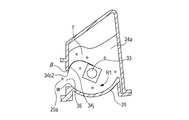
- the stirring means 26 will be further described. As shown in FIG. 3, the agitation means 26 includes a shaft member 33 that is rotatably supported in the developer storage chamber 24 a and an elastic sheet 34.
- the elastic sheet 34 is a flexible sheet member, and one end of the elastic sheet 34 is fixed to the shaft member 33.
- the longitudinal direction of the shaft member 33 coincides with the longitudinal direction of the process cartridge 5.
- the rotation locus of the free end (hereinafter referred to as “elastic sheet front end”) 34 c of the elastic sheet 34 overlaps the bottom 39 of the toner container 21, and the elastic sheet front end 34 c develops.
- the length of the elastic sheet 34 is set so that it can enter the chamber 29a. Therefore, when the elastic sheet 34 is positioned below the toner container 21, the toner accumulated in the toner container 21 in a bent state is agitated as the agitating means 26 rotates in contact with the bottom 39 of the toner container 21.
- the shaft member 33 further rotates and the elastic sheet 34 reaches the developing opening 35, the deflection of the elastic sheet 34 is released, and the elastic sheet tip 34c enters the developing chamber 29a.
- FIG. 1 [Development opening and elastic sheet]
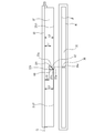
- FIG. 4 is a diagram showing the configuration of the development opening 35 and the elastic sheet 34 in this embodiment and the positional relationship in the longitudinal direction.
- the development opening 35 is provided between the developer storage chamber 24a and the development chamber 29a (see FIG. 3), and is an opening that communicates the developer storage chamber 24a and the development chamber 29a.
- the developing opening 35 is provided with a connecting portion 36 that connects and connects two sides of the developing opening 35 extending in the longitudinal direction. That is, the connecting portion 36 connects one end (opening lower end) 35a and the other end (opening upper end) 35b of the developing opening 35 in a direction orthogonal to the longitudinal direction.
- the connecting portion 36 itself is formed so as to extend in a direction orthogonal to the longitudinal direction.
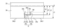
- the elastic sheet 34 is divided into a first transport part 34j, an intrusion part 34a, and an avoidance part 34b by a cut K that divides the elastic sheet 34.
- the first transport unit 34j is provided in a region that does not overlap the connecting unit 36 when viewed from the direction orthogonal to the longitudinal direction, and transports the developer from the developer storage chamber to the development chamber when the shaft member 33 rotates.
- the intrusion portion 34a is provided in a region overlapping with the connecting portion 36 when viewed from the direction orthogonal to the longitudinal direction, and when the shaft member 33 rotates, the intruding portion 34a wraps around the back of the connecting portion 36 and enters the developing chamber 29a.
- the avoiding portion 34b is a contact portion provided at a position where it comes into contact with the connecting portion 36 when the intruding portion 34a enters the developing chamber 29a.
- the avoiding portion 34b has a function of avoiding deformation of the entire elastic sheet 34 even when the elastic sheet 34 contacts the connecting portion 36.
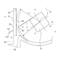
- FIGS. 5 to 8 and FIG. 5A to 5D are cross-sectional views A in FIG. 4 showing the behavior of the first transport portion 34j with respect to the developing opening 35, in which the developing roller 22 and the regulating member 23 are omitted.
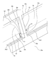
- 1 and 6 are perspective views showing the behavior of the intrusion portion 34a with respect to the developing opening 35.
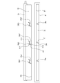
- FIG. 7A and 7B show the dimensional relationship between the elastic sheet 34 and the developing opening 35
- FIG. 7A is an explanatory diagram showing the dimensional relationship of the elastic sheet 34
- 7B is a cross-sectional view B in FIG. 4 showing the dimensional relationship of the developing opening 35, in which the developing roller 22 and the regulating member 23 are omitted.
- FIG. 8 is a figure which shows the behavior of the elastic sheet 34 when the avoidance part 34b is not provided.
- the behavior of the first transport unit 34j with respect to the developing opening 35 will be described with reference to FIGS. 5A to 5D.
- the shaft member 33 rotates in the direction of the arrow R1
- the first transport portion 34j approaches the developing opening 35 while rubbing the bottom shape 39 of the developer accommodating chamber 24a as shown in FIG. 5A.
- the front end (free end) 34c2 of the first transport unit 34j passes through the opening lower end 35a of the development opening 35, the first transport unit 34j is released from deformation, and the front end 34c2 enters the developing chamber 29a as shown in FIG. 5B. invade.
- the shaft member 33 further rotates in the direction of the arrow R1, so that the first transport portion 34j comes into contact with the opening upper end portion 35b of the developing opening 35 and is deformed again, and the developer storage chamber 24a. Proceed to.
- the tip 34c2 passes through the opening upper end 35b, the first transport unit 34j is released from the deformation and returns to the developer storage chamber 24a as shown in FIG. 5D.
- the toner T in the developer accommodating chamber 24a is conveyed to the developing chamber 29a.
- the intrusion portion 34a enters the region located on the back side of the connecting portion 36 when the connecting portion 36 is viewed from the developer storage chamber 24a in a direction (arrow A2 direction in FIG. 6) perpendicular to the longitudinal direction.
- the intrusion portion 34a contacts the connecting portion 36 in the vicinity of the opening lower end portion 35a, and starts to deform along the connecting portion side surface 36a that is a side surface portion of the connecting portion 36 substantially perpendicular to the longitudinal direction.
- the distal end 34g of the intrusion portion 34a passes through the connecting portion side surface 36a, the intrusion portion 34a is released from deformation as shown in FIG. 6, and the distal end 34c1 of the intrusion portion 34a enters the developing chamber 29a.
- the distance from the rotation center Q of the shaft member 33 to the tips 34c1 and 34c2 is L1
- the distance from the rotation center Q to one end 34e of the intrusion portion 34a is L2.
- L5 when the distance from the rotation center Q to the connecting portion back surface 36c that is the surface of the connecting portion 36 on the developing chamber 29a side is L5, L1> L2> L5 is set.
- the leading end 34c of the elastic sheet 34 can enter the developing chamber 29a in substantially the entire longitudinal direction including the periphery of the connecting portion 36. That is, both the tip 34c1 of the intrusion part 34a that forms the tip 34c of the elastic sheet 34 and the tip 34c2 of the first transport part 34j enter the developing chamber 29a. Thereby, the elastic sheet 34 can be agitated in the developing chamber 29a in substantially the entire longitudinal direction even when the connecting portion 36 is provided.
- the distance from the rotation center Q of the shaft member 33 to one end 34d of the avoiding portion 34b is L3, and the distance from the rotation center Q to the other end 34f of the avoiding portion 34b is L4.
- the distance from the rotation center Q to the connecting portion front surface 36b which is the surface of the connecting portion 36 on the developer accommodating chamber 24a side is L6, the relationship is L3> L6> L4.
- the avoiding portion 34b contacts the connecting portion 36 in the vicinity of the opening lower end portion 35a, and starts to deform along the front surface 36b of the connecting portion 36. Even when the intruding portion 34a enters the developing chamber 29a, the avoiding portion 34b does not enter the developing chamber 29a, and continues to rotate in the developer accommodating chamber 24a as the shaft member 33 rotates in the arrow direction R1.
- the cut K provided in the elastic sheet 34 is constituted by cuts K1, K2, K3, and K4.
- the cuts K1 and K2 forming the intrusion portion 34a are collectively referred to as a first cut K5. Further, the cuts K3 and K4 forming the avoidance part 34b are collectively referred to as a second cut K6.
- the intruding portion 34a and the notch K2 are viewed from the direction orthogonal to the axial direction of the shaft member 33 (the direction of the arrow A2 in FIG. 6) in a state where the intruding portion 34a has entered the back of the connecting portion 36, the intruding portion 34a overlaps with the connecting portion 36.
- the cut K2 is at a position intersecting with the connecting portion 36 (see FIGS. 4 and 6). That is, in the first cut K5, the cut K2 is an intersecting portion provided at a position intersecting with the connecting portion 36 when viewed from the direction orthogonal to the longitudinal direction. The presence of the cut K2 allows the intrusion portion 34a to enter the back of the connecting portion 36.
- the cuts K3 and K4 are cuts extending in a direction intersecting with the longitudinal direction of the shaft member 33 as shown in FIGS. 7A and 7B. That is, it extends in the direction approaching the shaft member 33 from the tip 34d of the avoiding portion 34b. Due to the presence of the cuts K3 and K4, as shown in FIG. 6, when the avoiding portion 34b comes into contact with the connecting portion 36, it is located upstream in the rotational direction of the shaft member 33 (direction indicated by R4 in FIG. 3). Can bend.
- the avoidance portion 34b is divided from the first transport portion 34j and the intrusion portion 34a by the cuts K3 and K4, the first transport portion 34j and the intrusion portion even if the avoidance portion 34b comes into contact with the connecting portion 36 and bends greatly. 34a is not greatly deformed. As a result, the intrusion portion 34a can surely enter the back of the connecting portion 36. As shown in FIG. 6, when the intruding portion 34 a enters the back of the connecting portion 36, the avoiding portion 34 b bends to the upstream side in the rotation direction of the shaft member 33 with respect to the elastic sheet tips (34 c 1, 34 c 2). become.
- the region 34k of the elastic member 34 that comes into contact with the connecting portion 36 is connected to the regions 34i and 34h at both ends thereof.
- the region 34k contacts the front surface 36b of the connecting portion 36 and deforms, the entire elastic sheet 34 is deformed around the fixed end 34f.
- the intrusion portion 34a is also deformed in a direction in which the tip 34c1 approaches the developer storage chamber 24a. As a result of this deformation, the intrusion portion 34a may be prevented from entering the developing chamber 29a from the developer storage chamber 24a.
- the contact portion that contacts the connecting portion 36 is separated from the first transport portion 34j and the intrusion portion 34a as the avoidance portion 34b. Yes.
- the connecting portion 36 comes into contact with the avoiding portion 34b, only the avoiding portion 34 bends to the upstream side in the rotation direction of the shaft member 33, so that the deformation of the intruding portion 34a is avoided, and the intruding portion 34a is located behind the connecting portion 36. It becomes easy to invade.
- the intrusion portion 34a after having entered the developing chamber 29a comes into contact with the connecting portion side surface 36a again in the vicinity of the opening upper end portion 35b of the developing opening 35 when the shaft member 33 further rotates in the arrow direction R1. Then, the developer returns to the developer accommodating chamber 24a while performing the same deformation as when passing through the opening lower end portion 35a.
- the elastic sheet 34 repeats these operations to transport the toner T in the developer accommodating chamber 24a to the developing chamber 29a even when the connecting portion 36 is provided in the developing opening 35, and the developing chamber 29a including the periphery of the connecting portion 36.
- the stirring inside can be performed. Thereby, it is possible to improve the toner packing in the developing chamber 29a and the toner T remaining around the connecting portion 36.
- FIG. 9 is a diagram illustrating the configuration and positional relationship between the developing opening 35 and the elastic sheet 37 according to the second embodiment.
- the intrusion portion 37a and the avoidance portion 37b are separated from each other by a cut K7 extending obliquely with respect to the connecting portion 36 from the free end of the elastic sheet 37.
- the cut K7 is the first cut in this embodiment, and extends in a direction intersecting with the connecting portion 36 to form an intrusion portion 37a.
- the cut K8 is a second cut that forms the avoidance portion (contact portion) 37b.
- the distance from the rotation center Q of the shaft member 33 to the elastic sheet tip 37c is L8, and the distance from the rotation center Q to the intersection 37e of the side surface 36a of the connecting portion 36 and the elastic sheet 37 is L7. Further, if the distance from the rotation center Q to the connecting portion back surface 36c is L5 (FIG. 7B), the relationship of L8> L7> L5 is necessary as in the first embodiment.
- the intrusion portion 37a has a surface that intersects the connecting portion 36 in the longitudinal direction, and has a configuration satisfying the relationship of L8> L7> L5. If this relationship is satisfied, the intrusion portion 37a can have another shape.
- the cut K8 extends in a direction approaching the shaft member 33 from the tip of the avoidance portion (contact portion) 37b.
- the distance from the rotation center Q to one end 37d of the avoidance part 37b is L9
- the distance from the rotation center Q to the other end 37f of the avoidance part 37b is L10.
- the distance from the rotation center Q to the connecting portion front surface 36b is L6 (FIG. 7B)
- the relationship of L9> L6> L10 is necessary as in the first embodiment.
- the avoidance part 37b can be bent to the upstream side in the rotation direction of the shaft member 33 by the cut K8 when contacting the connecting part 36. Thereby, deformation
- tip 37c1 and 37c2 can be prevented.
- the avoidance portion 37b can have another shape.
- the intruding portion 37a may wrap around the back of the connecting portion 36 and enter the developing chamber 29a. It can.
- the intrusion unit 37 can transport the toner in the developer storage chamber 24a to the development chamber 29a, and can stir the development chamber 29a over substantially the entire length including the periphery of the connecting portion 36. As a result, the toner T remains around the connecting portion 36 and the toner packing in the developing chamber 29a can be improved.
- FIG. 10 is a diagram illustrating the configuration of the development opening 35 and the elastic sheet 39 according to the third embodiment and the positional relationship in the longitudinal direction.
- a plurality of connecting portions 38a, 38b, and 38c are provided for the developing opening 35.
- a plurality of intruding portions 39a1, 39a2, 39a3 and avoiding portions 39b1, 39b2 are also provided in the elastic sheet 39.
- 39b3 Unlike the first embodiment, the connecting portions 38a, 38b, and 38c are connected to the straight line Z that connects the opening lower end portion 35a and the opening upper end portion 35b with an inclination.
- the number of the connecting portions 38 is not necessarily one for the developing opening 35, and a plurality of connecting portions 38 may be provided in accordance with a place to be reinforced and a degree to be reinforced.
- the elastic sheet 39 by providing the elastic sheet 39 with a plurality of intrusion portions 39a and avoidance portions 39b corresponding to the elastic sheet 39, the elastic sheet 39 can get over the connecting portion 38 substantially in the entire longitudinal direction as in the first embodiment.
- the connecting portion 38 that connects the developing opening 35 is not necessarily formed in the direction perpendicular to the longitudinal direction as in the first embodiment.
- any configuration may be used as long as one end portion and the other end portion of the development opening 35 are connected in a direction orthogonal to the longitudinal direction, and the developing opening 35 may be inclined with respect to the longitudinal direction as in the present embodiment.
- the elastic sheet 39 is provided with cuts K9, K10, K11, and K12.
- the cuts K9 and K10 are first cuts that form the intrusion portion 39a.
- the cuts K ⁇ b> 10 are formed in the direction intersecting with the connecting portion 38 in accordance with the inclination of the connecting portion 38. That is, the cut K10 is an intersecting portion that intersects the connecting portion 38 in the first cut.
- cuts K11 and K12 are second cuts that form the avoidance part 39b.
- the intrusion portion 39a can go around the back of the connecting portion 38 and enter the developing chamber 29a.
- the avoidance portion 39b is a contact portion that contacts the connecting portion 38 in the developer storage chamber. Similar to the first embodiment, the avoiding portion 39 functions to prevent the entire elastic sheet from being bent when it contacts the connecting portion 38.
- FIG. 11 is a diagram showing the configuration of the developing opening 35 and the elastic sheet 40 according to Example 4 and the positional relationship in the longitudinal direction.
- the elastic sheet 40 in the present embodiment is provided with cuts K13, K14, K15, and K16.
- the cuts K13 and K14 are first cuts that form the intrusion 40a1 and the intrusion 40a2. Further, the cuts K15 and K16 are second cuts that form the avoiding portion 40b.
- the first cuts K13 and K14 are T-shaped. That is, the cut K13 extends from the free end of the elastic sheet 40 in a direction intersecting the longitudinal direction, and the cut K14 extends from the cut K13 in two directions.
- two intrusion portions 40a1 and 40a2 are provided for one connection portion 36.
- FIG. 12 is a diagram showing the configuration of the developing opening 35 and the elastic sheet 41 and the positional relationship in the longitudinal direction according to the fifth embodiment
- FIG. 13 is a cross-sectional view in FIG. 12 showing the positional relationship between the elastic sheet 34 and the developing opening 35.
- the elastic sheet 41 of the present embodiment is provided with the elastic sheet 41 in order to avoid contact between the connecting portion 36 and the elastic sheet 41 instead of providing the avoiding part 34 b (FIG. 4) in Example 1.
- An opening (sheet opening) 41e is provided by cutting out.
- the length from the rotation center Q of the shaft member 33 to the one end 41d of the opening 41e is L11, and the distance from the rotation center Q to the connecting portion front surface 36b is L6, the relationship L11 ⁇ L6. is required.
- the intrusion portion 41a when the intrusion portion 41a enters the developing chamber 29a, the elastic sheet 41 does not contact the connecting portion 36 in a region other than the intrusion portion 41a. Therefore, the elastic sheet 41 is not deformed so that the tip 41c (41c1 and 41c2) does not approach the developer storage chamber 24a. As a result, the intrusion portion 41a can surely enter the developing chamber 29a.
- a cut K19 extends from the free end of the elastic sheet 41 so as to be connected to the opening 41e.
- the cut K19 and the opening 41e serve as a first cut that forms the intrusion portion 41a.
- the opening 41 e is an intersecting portion formed in a direction intersecting with the connecting portion 36.
Landscapes
- Physics & Mathematics (AREA)
- General Physics & Mathematics (AREA)
- Engineering & Computer Science (AREA)
- Computer Vision & Pattern Recognition (AREA)
- Dry Development In Electrophotography (AREA)
Abstract
装置を補強するために、現像剤収容室と現像室を連通する開口部に連結部を設けた場合でも現像剤収容室から現像室へトナーを良好に搬送することを目的とする。 現像剤を開口部から現像剤収容室の外部に搬送するシート部材は、シート部材の自由端から延び、長手方向と直交する方向から見て連結部と交差する位置にある第1の切込みによって形成された侵入部であって、現像剤収容室の内部から外部に侵入して、軸部材の長手方向と直交する方向から見て連結部と位置が重なる侵入部を有する。
Description
本発明は、画像形成装置および、画像形成装置に用いられる現像剤収容室、現像装置及び、プロセスカートリッジに関するものである。
ここで、画像形成装置とは、記録媒体に画像を形成するものである。例えば、電子写真画像形成プロセスを用いた電子写真複写機、電子写真プリンター(LEDプリンター、レーザビームプリンタなど)、電子写真ファクシミリ装置などが含まれる。
現像剤収容室とは内部に現像剤を収容するものである。また現像装置とは、現像剤担持体と、現像剤収容室とを有するものである。また、プロセスカートリッジとは,像担持体と、現像剤担持体を一体的にカートリッジ化し、このカートリッジを画像形成装置本体に対して着脱可能とするものである。
従来、電子写真画像形成プロセスを用いた画像形成装置においては、像担持体および像担持体に作用するプロセス手段を一体的にカートリッジ化して、このカートリッジを画像形成装置に着脱可能とするカートリッジ方式が採用されている。このカートリッジ方式によれば、装置のメンテナンスをサービスマンによらずユーザー自身で行うことができるので、格段に操作性を向上させることができる。そこで、このカートリッジ方式は、画像形成装置において広く用いられている。
従来、プロセスカートリッジには、像担持体に形成された静電潜像を現像剤によって現像する現像装置が設けられている。この現像装置は、現像剤担持体を内部に配置する現像室と、現像剤を内部に収容する現像剤収容室を有する。現像室と現像剤収容室の間には、現像剤が出入り可能なように開口部(現像開口)が設けられ、撹拌手段によって現像剤を現像剤収容室から現像剤収容室に供給するようにしている。
撹拌手段は、現像剤収容室に回転可能に設けられた軸部材と、軸部材に固定された弾性シートによって構成される。ここで撹拌手段によって、現像剤を良好に現像室に供給すること及び、現像室内で高密度化した現像剤をほぐすことを目的として、弾性シートの先端部を現像剤収容室から現像室に侵入させる構成が知られている(特許文献1参照)。
一方、現像剤の通り道である現像開口が現像装置に設けられることで現像装置の強度が低下する可能性がある。そこで、現像開口の端部のうち、現像剤担持体の軸線方向に伸びている対向する2辺を、リブ等の連結部で部分的に連結させ現像装置を補強する方法がある。
しかしこのとき、前述した弾性シートの先端部が連結部に妨げられて現像室に侵入できなくなる。この問題を解決するため、連結部と接触しないよう、弾性シートに、連結部と対応する位置において切り欠き形状を設ける構成がある(特許文献2参照)。しかしこの構成であっても、連結部の周囲で現像剤を現像室に搬送できなかったり、連結部の裏側に位置する現像剤をほぐすことができなくなる場合がある。
また、現像室内にも攪拌手段を別途設ける構成もあるが、撹拌手段が計2個必要となるためにコストアップや装置の大型化を招く場合がある(特許文献3参照)。
本発明は上記従来技術における課題を解決するためになされたものである。その目的は、装置を補強するために、現像剤収容室と現像室を連通する開口部に連結部を設けた場合でも現像剤収容室から現像室へトナーを良好に搬送することである。
上記目的を達成するための本発明の代表的な構成は、
現像剤を内部に収容する現像剤収容室において、
現像剤が通過する開口部と、
前記現像剤収容室の内部に回転可能に支持された軸部材と、
前記軸部材の長手方向と直交する方向における、前記開口部の一端部と他端部とを連結する連結部と、
前記軸部材に固定され、前記軸部材が回転した際に、現像剤を前記開口部から前記現像剤収容室の外部に搬送するシート部材と、
を備え、
前記シート部材は、前記シート部材の自由端から延び、前記長手方向と直交する方向から見て前記連結部と交差する位置にある第1の切込みによって形成された侵入部であって、前記現像剤収容室の内部から外部に侵入して、前記軸部材の長手方向と直交する方向から見て前記連結部と位置が重なる侵入部を有することを特徴とする。
現像剤を内部に収容する現像剤収容室において、
現像剤が通過する開口部と、
前記現像剤収容室の内部に回転可能に支持された軸部材と、
前記軸部材の長手方向と直交する方向における、前記開口部の一端部と他端部とを連結する連結部と、
前記軸部材に固定され、前記軸部材が回転した際に、現像剤を前記開口部から前記現像剤収容室の外部に搬送するシート部材と、
を備え、
前記シート部材は、前記シート部材の自由端から延び、前記長手方向と直交する方向から見て前記連結部と交差する位置にある第1の切込みによって形成された侵入部であって、前記現像剤収容室の内部から外部に侵入して、前記軸部材の長手方向と直交する方向から見て前記連結部と位置が重なる侵入部を有することを特徴とする。
また本発明の別の構成は、
像担持体に形成された潜像を現像する現像装置において、
現像剤を担持する現像剤担持体と、
前記現像剤担持体を内部に配する現像室と、
現像剤を内部に収容する現像剤収容室と、
前記現像室と前記現像剤収容室とを連通する開口部と、
前記現像剤収容室の内部に回転可能に支持された軸部材と、
前記軸部材に固定され、前記軸部材が回転した際に、現像剤を前記剤収容室から前記現像室に搬送するシート部材と、
前記軸部材の長手方向と直交する方向における、前記開口部の一端部と他端部とを連結する連結部と、
を備え、
前記シート部材は、前記シート部材の自由端から延び、前記長手方向と直交する方向から見て前記連結部と交差する位置にある第1の切込みによって形成された侵入部であって、前記現像剤収容室から前記現像室に侵入して、前記軸部材の長手方向と直交する方向から見て前記連結部と位置が重なる侵入部を有することを特徴とする。
像担持体に形成された潜像を現像する現像装置において、
現像剤を担持する現像剤担持体と、
前記現像剤担持体を内部に配する現像室と、
現像剤を内部に収容する現像剤収容室と、
前記現像室と前記現像剤収容室とを連通する開口部と、
前記現像剤収容室の内部に回転可能に支持された軸部材と、
前記軸部材に固定され、前記軸部材が回転した際に、現像剤を前記剤収容室から前記現像室に搬送するシート部材と、
前記軸部材の長手方向と直交する方向における、前記開口部の一端部と他端部とを連結する連結部と、
を備え、
前記シート部材は、前記シート部材の自由端から延び、前記長手方向と直交する方向から見て前記連結部と交差する位置にある第1の切込みによって形成された侵入部であって、前記現像剤収容室から前記現像室に侵入して、前記軸部材の長手方向と直交する方向から見て前記連結部と位置が重なる侵入部を有することを特徴とする。
また本発明の別の構成は、
画像形成装置本体に着脱可能なプロセスカートリッジにおいて、
潜像が形成される像担持体と、
前記潜像を現像するための現像剤を担持する現像剤担持体と、
前記現像剤担持体を内部に配する現像室と、
現像剤を内部に収容する現像剤収容室と、
前記現像室と前記現像剤収容室とを連通する開口部と、
前記現像剤収容室の内部に回転可能に支持された軸部材と、
前記軸部材に固定され、前記軸部材が回転した際に、現像剤を前記剤収容室から前記現像室に搬送するシート部材と、
前記軸部材の長手方向と直交する方向における、前記開口部の一端部と他端部とを連結する連結部と、
を備え、
前記シート部材は、前記シート部材の自由端から延び、前記長手方向と直交する方向から見て前記連結部と交差する位置にある第1の切込みによって形成された侵入部であって、前記現像剤収容室から前記現像室に侵入して、前記軸部材の長手方向と直交する方向から見て前記連結部と位置が重なる侵入部を有することを特徴とする。
画像形成装置本体に着脱可能なプロセスカートリッジにおいて、
潜像が形成される像担持体と、
前記潜像を現像するための現像剤を担持する現像剤担持体と、
前記現像剤担持体を内部に配する現像室と、
現像剤を内部に収容する現像剤収容室と、
前記現像室と前記現像剤収容室とを連通する開口部と、
前記現像剤収容室の内部に回転可能に支持された軸部材と、
前記軸部材に固定され、前記軸部材が回転した際に、現像剤を前記剤収容室から前記現像室に搬送するシート部材と、
前記軸部材の長手方向と直交する方向における、前記開口部の一端部と他端部とを連結する連結部と、
を備え、
前記シート部材は、前記シート部材の自由端から延び、前記長手方向と直交する方向から見て前記連結部と交差する位置にある第1の切込みによって形成された侵入部であって、前記現像剤収容室から前記現像室に侵入して、前記軸部材の長手方向と直交する方向から見て前記連結部と位置が重なる侵入部を有することを特徴とする。
また本発明の別の構成は、
記録媒体に画像を形成する画像形成装置において、
記録媒体を搬送する搬送手段と、
潜像が形成される像担持体と、
前記潜像を現像するための現像剤を担持する現像剤担持体と、
前記現像剤担持体を内部に配する現像室と、
現像剤を内部に収容する現像剤収容室と、
前記現像室と前記現像剤収容室とを連通する開口部と、
前記現像剤収容室の内部に回転可能に支持された軸部材と、
前記軸部材に固定され、前記軸部材が回転した際に、現像剤を前記剤収容室から前記現像室に搬送するシート部材と、
前記軸部材の長手方向と直交する方向における、前記開口部の一端部と他端部とを連結する連結部と、
を備え、
前記シート部材は、前記シート部材の自由端から延び、前記長手方向と直交する方向から見て前記連結部と交差する位置にある第1の切込みによって形成された侵入部であって、前記現像剤収容室から前記現像室に侵入して、前記軸部材の長手方向と直交する方向から見て前記連結部と位置が重なる侵入部を有することを特徴とする。
記録媒体に画像を形成する画像形成装置において、
記録媒体を搬送する搬送手段と、
潜像が形成される像担持体と、
前記潜像を現像するための現像剤を担持する現像剤担持体と、
前記現像剤担持体を内部に配する現像室と、
現像剤を内部に収容する現像剤収容室と、
前記現像室と前記現像剤収容室とを連通する開口部と、
前記現像剤収容室の内部に回転可能に支持された軸部材と、
前記軸部材に固定され、前記軸部材が回転した際に、現像剤を前記剤収容室から前記現像室に搬送するシート部材と、
前記軸部材の長手方向と直交する方向における、前記開口部の一端部と他端部とを連結する連結部と、
を備え、
前記シート部材は、前記シート部材の自由端から延び、前記長手方向と直交する方向から見て前記連結部と交差する位置にある第1の切込みによって形成された侵入部であって、前記現像剤収容室から前記現像室に侵入して、前記軸部材の長手方向と直交する方向から見て前記連結部と位置が重なる侵入部を有することを特徴とする。
現像剤収容室の開口部に、連結部を設けた場合でも良好なトナーの搬送を実現することができる。
<実施例1>
以下、本発明に係る現像装置、プロセスカートリッジ及び画像形成装置を図面に則して説明する。
以下、本発明に係る現像装置、プロセスカートリッジ及び画像形成装置を図面に則して説明する。
以下の説明において、プロセスカートリッジの長手方向を単に長手方向と呼ぶ。この長手方向は、像担持体(感光体ドラム)の長手方向(軸線方向)と一致している。またプロセスカートリッジの短手方向を単に短手方向とよぶ。この短手方向は、像担持体の回転軸と直交する方向であり、且つ記録媒体の搬送方向と一致している。また、プロセスカートリッジに関して、上方とはプロセスカートリッジを画像形成装置本体へ装着した状態での上方、下方とは同状態での下方をいうものとする。
[画像形成装置の全体構成]
まず、図2を参照して本実施例の画像形成装置の全体構成について説明する。図2に示すレーザビームプリンタ1は、電子写真画像形成プロセスによって記録媒体P(例えば、記録紙、OHPシート、布など)に現像剤による画像を形成する画像形成装置である。レーザープリンタ(以下、画像形成装置)1は画像形成装置本体1aと通信可能に接続されたパーソナルコンピュータなどの外部機器からの画像情報に応じて、画像を形成する。
まず、図2を参照して本実施例の画像形成装置の全体構成について説明する。図2に示すレーザビームプリンタ1は、電子写真画像形成プロセスによって記録媒体P(例えば、記録紙、OHPシート、布など)に現像剤による画像を形成する画像形成装置である。レーザープリンタ(以下、画像形成装置)1は画像形成装置本体1aと通信可能に接続されたパーソナルコンピュータなどの外部機器からの画像情報に応じて、画像を形成する。
ドラム形状である像担持体(以下、「感光体ドラム」という)2の表面は、帯電手段たる帯電ローラ3によって一様に帯電される。この感光体ドラム2に光学手段(露光手段)4から画像情報に応じたレーザ光Lを照射して感光体ドラム2に画像情報に応じた静電潜像を形成する。ここで形成された感光体ドラム2上の静電潜像を、後述の現像手段によって現像剤たるトナーによって現像することでトナー像を形成する。
一方、トナー像の形成と同期して、給送カセット6にセットした記録媒体Pをピックアップローラ7及びこれに圧接する圧接部材9で一枚ずつ分離給送する。そして、記録媒体Pを搬送ガイド8に沿って転写手段としての転写ローラ10へと搬送する。次いで、記録媒体Pは感光体ドラム2と一定の電圧を印加された転写ローラ10とで形成される転写ニップ部を通る。このとき感光体ドラム2上に形成されたトナー像が記録媒体Pに転写される。トナー像の転写を受けた記録媒体Pは搬送ガイド11で定着手段12へと搬送される。
定着手段12は駆動ローラ12a、及びヒータ12bを内蔵する定着ローラ12cを有する。定着手段12はこれら定着ローラ12cと、駆動ローラ12aとで形成されるニップ部を通過する記録媒体Pに熱及び圧力を印加して、転写されたトナー像を記録媒体Pに定着させる。その後、記録媒体Pは排出ローラ対13で搬送され、排出トレイ14へと排出される。なおピックアップローラ7、圧接部材9、搬送ガイド8、排出ローラ対13はレーザープリンタ1の内部で記録媒体を搬送する搬送手段を構成する。
[プロセスカートリッジ]
次に、本実施形態の画像形成装置本体に着脱可能なプロセスカートリッジ5について図3を参照して説明する。
次に、本実施形態の画像形成装置本体に着脱可能なプロセスカートリッジ5について図3を参照して説明する。
図3において、現像手段(以下、「現像装置」という)20は、現像剤として本実施例では実質的に磁性樹脂トナー粒子のみからなる(外添剤を含んでいてもよい)磁性1成分現像剤(トナー)Tを収容する現像剤容器(以下、「トナー容器」という)21を有する。
この現像装置20には、現像剤担持体たる現像ローラ22と、現像ローラ22の表面上にトナー層を形成する現像剤層厚規制手段(以下、「規制部材」という)23などが配置されている。
現像ローラ22は、固定磁石27を内蔵するローラである。トナーTをその表面に担持し、感光体ドラム2上に形成された静電潜像にトナーTを供給して可視画像を形成する。
規制部材23は、ブレード支持部23aおよび、このブレード支持部23aに一体成形もしくは接着されている現像ブレード23bによって形成される。規制部材23は、現像ローラに担持されるトナーTを帯電させ、さらに現像ローラに形成されるトナー層が一定の厚さにあるように規制する。
トナー容器21内のトナーTは、撹拌手段26が矢印R1方向に回転することによってトナーTの通り道である現像開口35を通じて現像ローラ22に送り出される。
そして、トナーTは回転する現像ローラ22と、規制部材23の現像ブレード23bとによって摩擦帯電電荷を付与されるとともに、一定の層厚となったトナー層を、現像ローラ22の表面に形成する。
現像ローラ22は感光体ドラム2に対して一定のクリアランスを保つため、両端に回転可能に支持した間隙保持部材であるスペーサコロ(図示せず)を配置している。そして、付勢ばね(図示せず)により現像ローラ22は感光体ドラム2に押圧されており、表面に形成されたトナー層を感光体ドラム2の現像領域に供給する。
そして、そのトナーTを感光体ドラム2上に形成された静電潜像に応じて感光体ドラム2へ転移させることによってトナー像を形成する。
現像ローラ22、規制部材23を支持する現像枠体24を、現像剤容器蓋(以下、「トナー容器蓋」という)29と超音波溶着などにより固定してトナー容器21が構成される。トナー容器21は、現像剤収容室24aと、現像室29aを有する。
現像剤収容室24aは主に、現像枠体24によって構成され、内部にトナーが収容される。また現像剤収容室24aの内部には撹拌手段26が配置される。撹拌手段26は、現像剤収容室24aから現像室29aにトナーを搬送する。
現像室29aは主にトナー容器蓋29によって構成され、その内部には現像ローラ22が配置される。現像ローラ22とトナー容器蓋29との間に生じる隙間には、隙間を塞ぐようにシート部材(吹き出し防止シート)25が設けられている。吹き出し防止シート25はこの隙間からトナーが漏洩するのを防止する。
感光体ユニット30には、静電潜像が形成される感光体ドラム2と、帯電ローラ3と、クリーニング手段31とが、廃トナー収容部32aを形成するドラム枠体32に配置されている。帯電ローラ3は感光層表面を一様に帯電させるための帯電手段である。クリーニング手段31は、記録媒体Pに転写されずに感光体ドラム2上に付着している残留トナーを感光体ドラム2の表面から掻き落とす。
感光体ドラム2は矢印A方向に回転駆動される。帯電ローラ3には一定の電圧が印加され、感光体ドラム2と接触し、感光体ドラム2の感光層表面を一様に帯電する。
次いで、前述の露光手段4(図2参照)からの画像情報に応じたレーザ光を露光開口5aを介して感光体ドラム2上に照射することにより、感光体ドラム2上に静電潜像を形成する。その後、現像ローラ22によって感光体ドラム2上にトナー像が形成される。
画像形成装置本体1aに設けられた転写手段たる転写ローラ10(図2参照)に、感光体ドラム2に形成されたトナー像と逆極性の電圧を印加して、トナー像を記録媒体Pに転写した後、クリーニング手段31によって感光体ドラム2上の残留トナーを除去する。
ここで、クリーニング手段31は、ブレード支持部31aおよび、ブレード支持部31aに一体成形もしくは接着されているクリーニング部材(以下、「クリーニングブレード」という)31bで構成される。そして、このクリーニングブレード31bを感光体ドラム2に当接させて感光体ドラム2に残留したトナーTを掻き落として廃トナー収容部32aに集める。
そして、図2に示すように、プロセスカートリッジ5は、画像形成装置本体1aに取り外し可能に装着される。
プロセスカートリッジ5が適切に画像形成装置本体1aに装着されると、画像形成装置本体側及びプロセスカートリッジ側の接点(図示せず)が電気的に接続される。そして、画像形成装置本体1aが備えた電圧印加手段(図示せず)から帯電ローラ3、現像ローラ22に、それぞれ所定の帯電バイアス、現像バイアスを印加可能な状態となる。
また、同様に、プロセスカートリッジ5が適正に画像形成装置本体1aに装着されると、画像形成装置本体側及びプロセスカートリッジ側の駆動伝達部(図示せず)が連結される。そして、画像形成装置本体1aが備える駆動モータなどの駆動手段(図示せず)からの駆動力がプロセスカートリッジ5に伝達可能な状態となる。
本実施例では、画像形成装置本体1aが備える駆動モータの駆動は、感光体ドラム2に伝達され、この駆動力が、ギア列などの駆動伝達部を介して現像ローラ22や、撹拌手段26などに伝達されるようになっている。
なお現像ローラ22や撹拌手段26などの、プロセスカートリッジ7の各要素を独立して駆動する駆動手段を画像形成装置本体1aに独立して複数設けることも可能である。
[撹拌手段]
撹拌手段26について更に説明する。図3に示すように、撹拌手段26は、現像剤収容室24aに回転可能に支持された軸部材33と、弾性シート34によって構成されている。弾性シート34は可撓性を有するシート部材であり、軸部材33にその一端が固定されている。軸部材33の長手方向はプロセスカートリッジ5の長手方向と一致する。
撹拌手段26について更に説明する。図3に示すように、撹拌手段26は、現像剤収容室24aに回転可能に支持された軸部材33と、弾性シート34によって構成されている。弾性シート34は可撓性を有するシート部材であり、軸部材33にその一端が固定されている。軸部材33の長手方向はプロセスカートリッジ5の長手方向と一致する。
本実施例では、軸部材33の回転時に、弾性シート34の自由端(以下、「弾性シート先端」と呼ぶ)34cの回転軌跡がトナー容器21の底39と重なり、且つ弾性シート先端34cが現像室29aに侵入できるよう、弾性シート34の長さを設定してある。従って、弾性シート34がトナー容器21の下方に位置するときはトナー容器21の底39と接触し、たわんだ状態でトナー容器21内に堆積するトナーを撹拌手段26の回転に伴って撹拌する。そして更に軸部材33が回転し、弾性シート34が現像開口35に達した際は、弾性シート34のたわみが解放され、弾性シート先端34cが現像室29aに侵入する。
[現像開口と弾性シート]
次に本発明の特徴である現像開口35と弾性シート34の構成及び挙動について図1及び図4~図7を用いて説明する。
次に本発明の特徴である現像開口35と弾性シート34の構成及び挙動について図1及び図4~図7を用いて説明する。
図4は本実施例における現像開口35と弾性シート34の構成及び長手方向における位置関係を示す図である。
図4に示すように、現像開口35は現像剤収容室24aと現像室29a(図3参照)の間に設けられ、現像剤収容室24aと現像室29aを連通する開口部である。現像開口35には、長手方向に伸びる現像開口35の2辺をつなぎ、連結する連結部36が設けられている。つまり連結部36は、長手方向と直交する方向における現像開口35の一端部(開口下方端部)35aと、他端部(開口上方端部)35bとを連結する。本実施例ではとくに連結部36自体が、長手方向と直交する方向に延びるように形成した。
また弾性シート34は弾性シート34を分割する切込みKにより、第一搬送部34jと、侵入部34aと、回避部34bに分割されている。第一搬送部34jは、長手方向と直交する方向からみて連結部36と重ならない領域に設けられ、軸部材33が回転した際に、現像剤を現像剤収容室から現像室に搬送する。侵入部34aは、長手方向と直交する方向からみて、連結部36と重なる領域に設けられ、軸部材33が回転した際に、連結部36の裏に回りこんで現像室29aに侵入する。また回避部34bは侵入部34aが現像室29aに侵入した際に、連結部36と当接する位置に設けられた当接部である。回避部34bは、弾性シート34が連結部36と当接しても、弾性シート34の全体が変形することを回避する機能を有する。第一搬送部34j、侵入部34a、回避部34bの構成については以下、詳細に説明する。
まず本構成における現像開口35と弾性シート34の挙動について図5~図8及び図1を用いて説明する。図5A~Dは現像開口35に対する第一搬送部34jの挙動を示した図4における断面図Aであり、現像ローラ22及び規制部材23は省略したものである。図1及び図6は現像開口35に対する侵入部34aの挙動を示した斜視図である。図7A、7Bは弾性シート34と現像開口35との寸法関係を示すものであり、図7Aは弾性シート34の寸法関係を示す説明図である。また図7Bは現像開口35の寸法関係を示した図4における断面図Bであり、現像ローラ22及び規制部材23は省略したものである。また、図8は回避部34bが設けられていない場合の弾性シート34の挙動を示す図である。
まず、図5A~Dを用いて現像開口35に対する第一搬送部34jの挙動を説明する。軸部材33が矢印R1方向に回転することで第一搬送部34jは図5Aに示すよう現像剤収容室24aの底形状39を擦りながら現像開口35へと近づいていく。そして現像開口35における開口下方端部35aを第一搬送部34jの先端(自由端)34c2が通過すると第一搬送部34jは変形から解放され、図5Bに示すよう、先端34c2は現像室29aに侵入する。先端34c2が現像室29aに侵入することで現像室29a内のトナーTを攪拌でき、現像室29a内でのトナーパッキングを防止できる。その後、図5Cに示すよう、軸部材33が矢印R1方向にさらに回転することで、第一搬送部34jは現像開口35における開口上方端部35bに接触し、再び変形しながら現像剤収容室24aへと進んでいく。そして先端34c2が開口上方端部35bを通過すると、第一搬送部34jは変形から解放され、図5Dに示すよう、現像剤収容室24aへと戻る。
以後この動作を繰り返すことで現像剤収容室24aのトナーTを現像室29aへと搬送する。
次に、図1及び図6~図8を用いて現像開口35に対する侵入部34a及び回避部34bの挙動を説明する。
侵入部34aは、現像剤収容室24aから、長手方向と直交する方向(図6の矢印A2方向)に連結部36を見たとき連結部36の裏側に位置する領域に侵入することを特徴とする。まず図1に示すよう、侵入部34aは開口下方端部35a付近で連結部36と接触し、長手方向と略直行する連結部36の側面部である連結部側面36aに沿って変形を始める。そして、侵入部34aの先端34gが連結部側面36aを通過すると、図6に示すよう侵入部34aは変形から解放され、侵入部34aの先端34c1は現像室29aへと入り込む。
ここで図7Aに示すよう、軸部材33の回転中心Qから先端34c1及び34c2までの距離をL1、回転中心Qから侵入部34aの一端34eまでの距離をL2とする。また、図7Bに示すよう回転中心Qから連結部36の現像室29a側の面である連結部背面36cまでの距離をL5とすると、L1>L2>L5となるよう設定する。
これにより、弾性シート34の先端34cが連結部36周りを含む長手方向略全域で現像室29aに侵入できる。すなわち弾性シート34の先端34cを形成する侵入部34aの先端34c1と、第一搬送部34jの先端34c2の両方が現像室29aに侵入する。これにより、弾性シート34は連結部36が設けられている場合でも現像室29a内を長手方向略全域で攪拌できる。
一方、回避部34bについては図7Aに示すよう、軸部材33の回転中心Qから回避部34bの一端34dまでの距離をL3、回転中心Qから回避部34bの他端34fまでの距離をL4とする。また、図7Bに示すよう回転中心Qから連結部36の現像剤収容室24a側の面である連結部正面36bまでの距離をL6とすると、L3>L6>L4の関係にある。
よって、回避部34bは開口下方端部35a付近で連結部36と接触し、連結部36の正面36bに沿って変形を始める。侵入部34aが現像室29aに侵入した場合でも回避部34bは現像室29aに侵入することはなく、軸部材33の矢印方向R1方向への回転とともに現像剤収容室24a内を回り続ける。
ここで図7Aに示すように、弾性シート34に設けられた切込みKは、切込みK1、K2、K3、K4によって構成される。
なお、侵入部34aを形成する切込みK1とK2を合わせて特に第1の切込みK5と呼ぶ。また、回避部34bを形成する切込みK3とK4を合わせて、特に第2の切込みK6と呼ぶ。
ここで侵入部34aが、連結部36の裏に侵入した状態で、軸部材33の軸線方向と直交する方向(図6の矢印A2方向)から侵入部34aと切込みK2を見ると、前記侵入部34aは連結部36と位置が重なる。また切込みK2は連結部36と交差する位置にある(図4、図6参照)。すなわち第1の切込みK5の内、切込みK2は、長手方向と直交する方向から見て連結部36と交差する位置に設けられた交差部である。切込みK2があることによって、侵入部34aは、連結部36の裏に侵入することができる。
一方、切込みK3および、切込みK4は、図7A、7Bに示すように、軸部材33の長手方向と交差する方向に延びる切込みである。つまり回避部34bの先端34dから、軸部材33に近づく方向に延びる。この切込みK3、K4があることによって、図6に示されるように回避部34bは連結部36と当接すると、軸部材33の回転方向(図3のR4で示す方向)において、上流側におおきく撓むことができる。
切込みK3及びK4によって、回避部34bが第一搬送部34jおよび侵入部34aから分割されているので、回避部34bが連結部36と当接して大きく撓んでも、第一搬送部34jおよび侵入部34aが大きく変形することがない。その結果、侵入部34aは確実に連結部36の裏に侵入することができる。図6に示されるように侵入部34aが連結部36の裏に侵入する際には、回避部34bは弾性シート先端(34c1、34c2)よりも軸部材33の回転方向における上流側に撓むことになる。
仮に図8に示すように、弾性部材34に切込みK3及びK4がない場合には、連結部36と当接する弾性部材34の領域34kは、その両端において領域34i、34hとつながった状態となる。その結果、領域34kが連結部36の正面36bと当接して変形した場合は、弾性シート34の全体が、固定端34fを中心として変形してしまう。これにより、侵入部34aもその先端34c1を現像剤収容室24aに近づける方向に変形してしまう。この変形の結果、侵入部34aが現像剤収容室24aから、現像室29aに侵入することが妨げられる可能性がある。
以上のことから、本実施例では弾性シート34に、切込みK3及びK4を設けることで、連結部36と当接する当接部を、第一搬送部34jと侵入部34aから切り離して回避部34bとしている。連結部36が回避部34bと当接すると、回避部34のみが軸部材33の回転方向上流側に撓むことで、侵入部34aの変形が回避され、侵入部34aは連結部36の裏に侵入しやすくなる。
一方、現像室29aに侵入した後の侵入部34aは、軸部材33が矢印方向R1方向へ更に回転すると、現像開口35における開口上方端部35b付近において再び連結部側面36aと接触する。そして開口下方端部35a通過時と同様の変形を行いながら現像剤収容室24aへと戻る。
弾性シート34はこれらの動作を繰り返すことで現像開口35に連結部36を設けた場合でも現像剤収容室24aのトナーTを現像室29aに搬送し、連結部36の周りを含めた現像室29a内の攪拌を行うことができる。これにより、現像室29a内におけるトナーパッキングや連結部36の周りにトナーTが残ることを改善できる。
弾性シート34はこれらの動作を繰り返すことで現像開口35に連結部36を設けた場合でも現像剤収容室24aのトナーTを現像室29aに搬送し、連結部36の周りを含めた現像室29a内の攪拌を行うことができる。これにより、現像室29a内におけるトナーパッキングや連結部36の周りにトナーTが残ることを改善できる。
<実施例2>
次に実施例2に係る現像装置20について説明する。なお、現像装置の基本構成やこれが用いられる画像形成装置の構成は前述した実施例1と同様であるため、ここでは実施例1と同様の機能を有する部材は同一符号を付して説明を省略し、実施例1と異なる部分についてのみ説明する。
次に実施例2に係る現像装置20について説明する。なお、現像装置の基本構成やこれが用いられる画像形成装置の構成は前述した実施例1と同様であるため、ここでは実施例1と同様の機能を有する部材は同一符号を付して説明を省略し、実施例1と異なる部分についてのみ説明する。
図9は実施例2に係る現像開口35と弾性シート37の構成及び位置関係を示した図である。本実施例における弾性シート37には、弾性シート37の自由端から、連結部36に対して斜めに伸びる切込みK7によって侵入部37aと回避部37bとが区切られる。切込みK7は本実施例における第1の切込みであって、連結部36と交差する方向に延び、侵入部37aを形成する。一方、切込みK8は、回避部(当接部)37bを形成する第2の切込みである。
ここで、軸部材33の回転中心Qから弾性シート先端37cまでの距離をL8、回転中心Qから連結部36の側面36aと弾性シート37の交点37eまでの距離をL7とする。また、回転中心Qから連結部背面36cまでの距離をL5(図7B)とすると、実施例1と同様に、L8>L7>L5の関係が必要である。
このように侵入部37aは長手方向において連結部36と交差する面を有し、L8>L7>L5の関係を満たす構成をとる。この関係を満たせば侵入部37aを他の形状とすることも可能である。
一方、切込みK8は、回避部(当接部)37bの先端から軸部材33に近づく方向に延びる。ここで回避部37bに関して、回転中心Qから回避部37bの一端37dまでの距離をL9、回転中心Qから回避部37bの他端37fまでの距離をL10とする。また、回転中心Qから連結部正面36bまでの距離をL6(図7B)とすると、実施例1と同様に、L9>L6>L10の関係が必要である。
回避部37bは、連結部36と接触した際、切込みK8によって軸部材33の回転方向上流側に撓むことができる。これにより弾性シート先端37c1及び37c2の変形を防止できる。L9>L6>L10の関係を満たす構成であれば、回避部37bを他の形状とすることも可能である。
よって本構成でも実施例1と同様に、現像開口35に連結部36を設けて補強を行った場合でも、侵入部37aが連結部36の裏に回りこんで、現像室29aに侵入することができる。侵入部37は現像剤収容室24aのトナーを現像室29aに搬送し、連結部36の周りを含めた長手略全域で現像室29a内の攪拌を行うことができる。これにより、連結部36の周りにトナーTが残ることや現像室29a内でのトナーパッキングを改善できる。
<実施例3>
次に実施例3に係る現像装置20について説明する。なお、現像装置の基本構成やこれが用いられる画像形成装置の構成は前述した実施例1と同様であるため、ここでは実施例1と同様の機能を有する部材は同一符号を付して説明を省略し、実施例1と異なる部分についてのみ説明する。
次に実施例3に係る現像装置20について説明する。なお、現像装置の基本構成やこれが用いられる画像形成装置の構成は前述した実施例1と同様であるため、ここでは実施例1と同様の機能を有する部材は同一符号を付して説明を省略し、実施例1と異なる部分についてのみ説明する。
図10は実施例3に係る現像開口35と弾性シート39の構成及び長手方向の位置関係を示した図である。本実施例では現像開口35に対して複数の連結部38a、38b、38cが設けられており、これに対応して弾性シート39にも複数の侵入部39a1、39a2、39a3と回避部39b1、39b2、39b3が設けられている。また、連結部38a、38b、38cも実施例1とは異なり、開口下方端部35aと開口上方端部35bを鉛直につなぐ直線Zに対して傾斜をもってつながっている。
このように連結部38の数も現像開口35に対して1つである必要はなく、補強したい場所や補強したい度合いに合わせて複数の連結部38を設けても良い。この場合、弾性シート39にもこれに対応した複数の侵入部39aと回避部39bを設けることで、実施例1と同様に弾性シート39は連結部38を長手略全域で乗り越えることができる。
また、現像開口35をつなぐ連結部38も実施例1のように長手方向に対して必ずしも垂直方向に形成する必要はない。つまり長手方向と直交する方向における、現像開口35の一端部と他端部を連結する構成であればよく、本実施例のように長手方向に対して傾斜をもって形成しても良い。
本実施例において、弾性シート39には、切込みK9,K10,K11,K12が設けられる。切込みK9及び切込みK10は、侵入部39aを形成する第1の切込みである。本実施例では、連結部38の傾斜に合わせて、連結部38と交差する方向に切込みK10を形成した。すなわち切込みK10は、第1の切込みにおいて、連結部38と交差する交差部である。
また、切込みK11とK12は回避部39bを形成する第2の切込みである。
実施例1と同様に、侵入部39aは連結部38の裏に回りこみ、現像室29aに侵入することができる。
また回避部39bは、現像剤収容室において、連結部38と当接する当接部である。実施例1と同様に回避部39は、連結部38と当接した際、弾性シート全体が撓むことを抑制する働きをする。
<実施例4>
次に実施例4に係る現像装置20について説明する。なお、現像装置の基本構成やこれが用いられる画像形成装置の構成は前述した実施例1と同様であるため、ここでは実施例1と同様の機能を有する部材は同一符号を付して説明を省略し、実施例1と異なる部分についてのみ説明する。
次に実施例4に係る現像装置20について説明する。なお、現像装置の基本構成やこれが用いられる画像形成装置の構成は前述した実施例1と同様であるため、ここでは実施例1と同様の機能を有する部材は同一符号を付して説明を省略し、実施例1と異なる部分についてのみ説明する。
図11は実施例4に係る現像開口35と弾性シート40の構成及び長手方向の位置関係を示した図である。本実施例における弾性シート40は、切込みK13,K14,K15,K16が設けられる。切込みK13とK14は、侵入部40a1と侵入部40a2を形成する第1の切込みである。また、切込みK15とK16は回避部40bを形成する第2の切込みである。
本実施例において、第1の切込みK13及びK14は、T字形状を成す。すなわち切込みK13は弾性シート40の自由端から、長手方向と交差する方向に延び、切込みK14は切込みK13から二方向に分岐して延びている。これにより1つの連結部36に対して2つの侵入部40a1、40a2が設けられている。
1つの連結部36に対して侵入部を複数設けることで、より効果的にトナーの搬送と撹拌が可能となる。
<実施例5>
次に実施例5に係る現像装置20について説明する。なお、現像装置の基本構成やこれが用いられる画像形成装置の構成は前述した実施例1と同様であるため、ここでは実施例1と同様の機能を有する部材は同一符号を付して説明を省略し、実施例1と異なる部分についてのみ説明する。
次に実施例5に係る現像装置20について説明する。なお、現像装置の基本構成やこれが用いられる画像形成装置の構成は前述した実施例1と同様であるため、ここでは実施例1と同様の機能を有する部材は同一符号を付して説明を省略し、実施例1と異なる部分についてのみ説明する。
図12は実施例5に係る現像開口35と弾性シート41の構成及び長手方向の位置関係を示した図であり、図13は弾性シート34と現像開口35の位置関係を示した図12における断面図Cである。
図12に示すよう、本実施形態の弾性シート41は、実施例1における回避部34b(図4)を設ける代わりに、連結部36と弾性シート41との接触を回避するため、弾性シート41を切り欠いて開口部(シート開口部)41eが設けられている。この場合図13に示すよう、軸部材33の回転中心Qと開口部41eの一端41dまでの長さをL11、回転中心Qから連結部正面36bまでの距離をL6とすると、L11<L6の関係が必要である。
このような弾性シート41を用いた場合、侵入部41aが現像室29aに侵入する際には、弾性シート41は、侵入部41a以外の領域において連結部36と接触しない。そのため弾性シート41は変形によって、その先端41c(41c1及び41c2)を現像剤収容室24a側に近づけることはない。その結果、侵入部41aを確実に、現像室29aに侵入させることができる。
なお本実施例において、開口部41eとつながるように弾性シート41の自由端から切込みK19が延びている。切込みK19及び開口部41eは、侵入部41aを形成する第1の切込みとなる。開口部41eは、連結部36と交差する方向に形成された交差部である。
本発明は上記実施の形態に制限されるものではなく、本発明の精神及び範囲から離脱することなく、様々な変更及び変形が可能である。従って、本発明の範囲を公にするために以下の請求項を添付する。
1 レーザビームプリンタ
1a 装置本体
2 感光体ドラム
3 帯電ローラ
5 プロセスカートリッジ
20 現像ユニット
21 トナー容器
22 現像ローラ
23 規制部材
24 現像枠体
26 撹拌手段
29 トナー容器蓋
30 感光体ユニット
31 クリーニング手段
32 ドラム枠体
33 軸部材
34 弾性シート
34a 侵入部
34b 回避部
34c 弾性シート先端
35 現像開口
36 連結部
36a 連結部側面
36b 連結部正面
36c 連結部背面
35a 開口下方端部
35b 開口上方端部
K5 第1の切込み
K6 第2の切込み
1a 装置本体
2 感光体ドラム
3 帯電ローラ
5 プロセスカートリッジ
20 現像ユニット
21 トナー容器
22 現像ローラ
23 規制部材
24 現像枠体
26 撹拌手段
29 トナー容器蓋
30 感光体ユニット
31 クリーニング手段
32 ドラム枠体
33 軸部材
34 弾性シート
34a 侵入部
34b 回避部
34c 弾性シート先端
35 現像開口
36 連結部
36a 連結部側面
36b 連結部正面
36c 連結部背面
35a 開口下方端部
35b 開口上方端部
K5 第1の切込み
K6 第2の切込み
Claims (16)
- 現像剤を内部に収容する現像剤収容室において、
現像剤が通過する開口部と、
前記現像剤収容室の内部に回転可能に支持された軸部材と、
前記軸部材に固定され、前記軸部材が回転した際に、現像剤を前記開口部から前記現像剤収容室の外部に搬送するシート部材と、
前記軸部材の長手方向と直交する方向における、前記開口部の一端部と他端部とを連結する連結部と、
を備え、
前記シート部材は、前記シート部材の自由端から延び、前記長手方向と直交する方向から見て前記連結部と交差する位置にある第1の切込みによって形成された侵入部であって、前記現像剤収容室の内部から外部に侵入して、前記軸部材の長手方向と直交する方向から見て前記連結部と位置が重なる侵入部を有することを特徴とする現像剤収容室。 - 前記シート部材は、前記長手方向と交差する方向に延びた第2の切込みによって形成された当接部であって、前記侵入部が前記現像剤収容室の外部に侵入する際に、前記現像剤収容室の内部にて前記連結部と当接し、前記シート部材の前記自由端よりも、前記軸部材の回転方向上流側に撓む当接部を有することを特徴とする請求項1に記載の現像剤収容室。
- 前記シート部材は、前記侵入部が前記現像剤収容室の外部に侵入する際に、前記シート部材が前記現像剤収容室の内部にて前記連結部と当接しないよう、シート開口部を有していることを特徴とする請求項1に記載の現像剤収容室。
- 前記侵入部は、前記連結部と接触して変形することで、前記現像剤収容室の外部に侵入することを特徴とする請求項1に記載の現像剤収容室。
- 前記第1の切込みは、前記シート部材の前記自由端から、前記軸部材の長手方向と交差する方向に延びた後、二方向に分岐することで、前記侵入部を二つ形成することを特徴とする請求項1に記載の現像剤収容室。
- 像担持体に形成された潜像を現像する現像装置において、
現像剤を担持する現像剤担持体と、
前記現像剤担持体を内部に配する現像室と、
現像剤を内部に収容する現像剤収容室と、
前記現像室と前記現像剤収容室とを連通する開口部と、
前記現像剤収容室の内部に回転可能に支持された軸部材と、
前記軸部材に固定され、前記軸部材が回転した際に、現像剤を前記剤収容室から前記現像室に搬送するシート部材と、
前記軸部材の長手方向と直交する方向における、前記開口部の一端部と他端部とを連結する連結部と、
を備え、
前記シート部材は、前記シート部材の自由端から延び、前記長手方向と直交する方向から見て前記連結部と交差する位置にある第1の切込みによって形成された侵入部であって、前記現像剤収容室から前記現像室に侵入して、前記軸部材の長手方向と直交する方向から見て前記連結部と位置が重なる侵入部を有することを特徴とする現像装置。 - 前記シート部材は、前記長手方向と交差する方向に延びた第2の切込みによって形成された当接部であって、前記侵入部が前記現像室に侵入する際に、前記現像剤収容室の内部にて前記連結部と当接し、前記シート部材の前記自由端よりも、前記軸部材の回転方向上流側に撓む当接部を有することを特徴とする請求項6に記載の現像装置。
- 前記シート部材は、前記侵入部が前記現像室に侵入した際に、前記シート部材が前記現像剤収容室の内部にて前記連結部と当接しないよう、シート開口部を有していることを特徴とする請求項6に記載の現像装置。
- 前記侵入部は、前記連結部と接触して変形することで、前記現像室に侵入することを特徴とする請求項6に記載の現像装置。
- 前記第1の切込みは、前記シート部材の前記自由端から、前記軸部材の長手方向と交差する方向に延びた後、二方向に分岐することで、前記侵入部を二つ形成することを特徴とする請求項6に記載の現像装置。
- 画像形成装置本体に着脱可能なプロセスカートリッジにおいて、
潜像が形成される像担持体と、
前記潜像を現像するための現像剤を担持する現像剤担持体と、
前記現像剤担持体を内部に配する現像室と、
現像剤を内部に収容する現像剤収容室と、
前記現像室と前記現像剤収容室とを連通する開口部と、
前記現像剤収容室の内部に回転可能に支持された軸部材と、
前記軸部材に固定され、前記軸部材が回転した際に、現像剤を前記剤収容室から前記現像室に搬送するシート部材と、
前記軸部材の長手方向と直交する方向における、前記開口部の一端部と他端部とを連結する連結部と、
を備え、
前記シート部材は、前記シート部材の自由端から延び、前記長手方向と直交する方向から見て前記連結部と交差する位置にある第1の切込みによって形成された侵入部であって、前記現像剤収容室から前記現像室に侵入して、前記軸部材の長手方向と直交する方向から見て前記連結部と位置が重なる侵入部を有することを特徴とするプロセスカートリッジ。 - 前記シート部材は、前記長手方向と交差する方向に延びた第2の切込みによって形成された当接部であって、前記侵入部が前記現像室に侵入する際に、前記現像剤収容室の内部にて前記連結部と当接し、前記シート部材の前記自由端よりも、前記軸部材の回転方向上流側に撓む当接部を有することを特徴とする請求項11に記載のプロセスカートリッジ。
- 前記シート部材は、前記侵入部が前記現像剤収容室の外部に侵入した際に、前記シート部材が前記現像剤収容室の内部にて前記連結部と当接しないよう、シート開口部を有していることを特徴とする請求項11に記載のプロセスカートリッジ。
- 前記侵入部は、前記連結部と接触して変形することで、前記現像室に侵入することを特徴とする請求項11に記載のプロセスカートリッジ。
- 前記第1の切込みは、前記シート部材の前記自由端から、前記軸部材の長手方向と交差する方向に延びた後、二方向に分岐することで、前記侵入部を二つ形成することを特徴とする請求項11に記載のプロセスカートリッジ。
- 記録媒体に画像を形成する画像形成装置において、
記録媒体を搬送する搬送手段と、
潜像が形成される像担持体と、
前記潜像を現像するための現像剤を担持する現像剤担持体と、
前記現像剤担持体を内部に配する現像室と、
現像剤を内部に収容する現像剤収容室と、
前記現像室と前記現像剤収容室とを連通する開口部と、
前記現像剤収容室の内部に回転可能に支持された軸部材と、
前記軸部材に固定され、前記軸部材が回転した際に、現像剤を前記剤収容室から前記現像室に搬送するシート部材と、
前記軸部材の長手方向と直交する方向における、前記開口部の一端部と他端部とを連結する連結部と、
を備え、
前記シート部材は、前記シート部材の自由端から延び、前記長手方向と直交する方向から見て前記連結部と交差する位置にある第1の切込みによって形成された侵入部であって、前記現像剤収容室から前記現像室に侵入して、前記軸部材の長手方向と直交する方向から見て前記連結部と位置が重なる侵入部を有することを特徴とする画像形成装置。
Priority Applications (3)
| Application Number | Priority Date | Filing Date | Title |
|---|---|---|---|
| JP2013548025A JP5815047B2 (ja) | 2011-12-08 | 2011-12-08 | 現像剤収容室、現像装置、プロセスカートリッジ、画像形成装置 |
| PCT/JP2011/078436 WO2013084340A1 (ja) | 2011-12-08 | 2011-12-08 | 現像剤収容室、現像装置、プロセスカートリッジ、画像形成装置 |
| US13/707,238 US9031475B2 (en) | 2011-12-08 | 2012-12-06 | Developer containing chamber, developing device, process cartridge, and image forming apparatus |
Applications Claiming Priority (1)
| Application Number | Priority Date | Filing Date | Title |
|---|---|---|---|
| PCT/JP2011/078436 WO2013084340A1 (ja) | 2011-12-08 | 2011-12-08 | 現像剤収容室、現像装置、プロセスカートリッジ、画像形成装置 |
Publications (1)
| Publication Number | Publication Date |
|---|---|
| WO2013084340A1 true WO2013084340A1 (ja) | 2013-06-13 |
Family
ID=48572084
Family Applications (1)
| Application Number | Title | Priority Date | Filing Date |
|---|---|---|---|
| PCT/JP2011/078436 Ceased WO2013084340A1 (ja) | 2011-12-08 | 2011-12-08 | 現像剤収容室、現像装置、プロセスカートリッジ、画像形成装置 |
Country Status (3)
| Country | Link |
|---|---|
| US (1) | US9031475B2 (ja) |
| JP (1) | JP5815047B2 (ja) |
| WO (1) | WO2013084340A1 (ja) |
Cited By (1)
| Publication number | Priority date | Publication date | Assignee | Title |
|---|---|---|---|---|
| JP2019211646A (ja) * | 2018-06-06 | 2019-12-12 | 京セラドキュメントソリューションズ株式会社 | 現像剤撹拌部材、現像剤補給ユニット、画像形成装置 |
Citations (2)
| Publication number | Priority date | Publication date | Assignee | Title |
|---|---|---|---|---|
| JP2002040788A (ja) * | 2000-07-28 | 2002-02-06 | Seiko Epson Corp | トナーカートリッジ及び攪拌器 |
| JP2007304281A (ja) * | 2006-05-10 | 2007-11-22 | Fuji Xerox Co Ltd | 粉体供給器、粉体供給器への粉体充填方法、及び画像形成装置 |
Family Cites Families (4)
| Publication number | Priority date | Publication date | Assignee | Title |
|---|---|---|---|---|
| JPH02285374A (ja) | 1989-04-27 | 1990-11-22 | Canon Inc | 現像装置及びプロセスカートリッジ |
| JP4164420B2 (ja) | 2003-08-22 | 2008-10-15 | キヤノン株式会社 | 現像装置及びこれを用いたプロセスカートリッジ並びに画像形成装置 |
| JP4595959B2 (ja) * | 2007-05-07 | 2010-12-08 | 富士ゼロックス株式会社 | 現像剤補給容器および画像形成装置 |
| JP4918127B2 (ja) * | 2009-11-04 | 2012-04-18 | 株式会社沖データ | 現像剤収容器、現像装置及び画像形成装置 |
-
2011
- 2011-12-08 JP JP2013548025A patent/JP5815047B2/ja active Active
- 2011-12-08 WO PCT/JP2011/078436 patent/WO2013084340A1/ja not_active Ceased
-
2012
- 2012-12-06 US US13/707,238 patent/US9031475B2/en active Active
Patent Citations (2)
| Publication number | Priority date | Publication date | Assignee | Title |
|---|---|---|---|---|
| JP2002040788A (ja) * | 2000-07-28 | 2002-02-06 | Seiko Epson Corp | トナーカートリッジ及び攪拌器 |
| JP2007304281A (ja) * | 2006-05-10 | 2007-11-22 | Fuji Xerox Co Ltd | 粉体供給器、粉体供給器への粉体充填方法、及び画像形成装置 |
Cited By (2)
| Publication number | Priority date | Publication date | Assignee | Title |
|---|---|---|---|---|
| JP2019211646A (ja) * | 2018-06-06 | 2019-12-12 | 京セラドキュメントソリューションズ株式会社 | 現像剤撹拌部材、現像剤補給ユニット、画像形成装置 |
| JP7131096B2 (ja) | 2018-06-06 | 2022-09-06 | 京セラドキュメントソリューションズ株式会社 | 現像剤撹拌部材、現像剤補給ユニット、画像形成装置 |
Also Published As
| Publication number | Publication date |
|---|---|
| US9031475B2 (en) | 2015-05-12 |
| US20130149010A1 (en) | 2013-06-13 |
| JP5815047B2 (ja) | 2015-11-17 |
| JPWO2013084340A1 (ja) | 2015-04-27 |
Similar Documents
| Publication | Publication Date | Title |
|---|---|---|
| CN102109797B (zh) | 显影盒 | |
| US10838348B2 (en) | Developing cartridge including developing gear cover | |
| JP5293663B2 (ja) | 現像カートリッジおよびプロセスカートリッジ | |
| JP2003005612A (ja) | プロセスカートリッジ | |
| CN110568740B (zh) | 运送设备、清洁设备、显影设备、处理盒及图像形成装置 | |
| CN101470383B (zh) | 显影盒 | |
| JP7206856B2 (ja) | トナー搬送装置、現像装置、プロセスカートリッジ、及び、画像形成装置 | |
| JP5418314B2 (ja) | 現像装置および画像形成装置 | |
| JP6525556B2 (ja) | 現像装置、プロセスカートリッジ及び電子写真画像形成装置 | |
| CN106597821B (zh) | 供给装置,清洁装置,显影装置,处理盒和成像设备 | |
| JP2007298908A (ja) | プロセスカートリッジ、画像形成装置及びプロセスカートリッジの組立て方法 | |
| JP5815047B2 (ja) | 現像剤収容室、現像装置、プロセスカートリッジ、画像形成装置 | |
| JP5397616B2 (ja) | 現像装置、プロセスユニット及び画像形成装置 | |
| JP2015197517A (ja) | 画像形成装置 | |
| JP4872936B2 (ja) | 画像形成装置および現像カートリッジ | |
| JP5967256B2 (ja) | 現像装置および画像形成装置 | |
| JP6682233B2 (ja) | 収容ユニット、クリーニング装置、プロセスカートリッジ、および画像形成装置 | |
| JP2007226060A (ja) | 現像剤収納容器、現像装置、プロセスカートリッジ、及び画像形成装置 | |
| JP6525241B2 (ja) | トナー補給装置及びこれを備える画像形成装置 | |
| JP7255148B2 (ja) | トナー搬送装置、現像装置、プロセスカートリッジ、及び、画像形成装置 | |
| JP4804174B2 (ja) | 現像装置、プロセスカートリッジ、及び電子写真画像形成装置 | |
| JP2012083782A (ja) | 現像カートリッジ | |
| JP2017090744A (ja) | 現像装置、プロセスカートリッジ及び画像形成装置 | |
| JP2021089420A (ja) | 回転部材、現像剤収納容器、現像装置、プロセスカートリッジ、及び、画像形成装置 | |
| JPH05273856A (ja) | 電子写真装置の現像器 |
Legal Events
| Date | Code | Title | Description |
|---|---|---|---|
| 121 | Ep: the epo has been informed by wipo that ep was designated in this application |
Ref document number: 11877046 Country of ref document: EP Kind code of ref document: A1 |
|
| ENP | Entry into the national phase |
Ref document number: 2013548025 Country of ref document: JP Kind code of ref document: A |
|
| NENP | Non-entry into the national phase |
Ref country code: DE |
|
| 122 | Ep: pct application non-entry in european phase |
Ref document number: 11877046 Country of ref document: EP Kind code of ref document: A1 |