WO2013080706A1 - 車載カメラの取り付け装置 - Google Patents
車載カメラの取り付け装置 Download PDFInfo
- Publication number
- WO2013080706A1 WO2013080706A1 PCT/JP2012/077390 JP2012077390W WO2013080706A1 WO 2013080706 A1 WO2013080706 A1 WO 2013080706A1 JP 2012077390 W JP2012077390 W JP 2012077390W WO 2013080706 A1 WO2013080706 A1 WO 2013080706A1
- Authority
- WO
- WIPO (PCT)
- Prior art keywords
- vehicle
- windshield
- fixed
- camera
- support plate
- Prior art date
Links
Images


Classifications
-
- B—PERFORMING OPERATIONS; TRANSPORTING
- B60—VEHICLES IN GENERAL
- B60R—VEHICLES, VEHICLE FITTINGS, OR VEHICLE PARTS, NOT OTHERWISE PROVIDED FOR
- B60R11/00—Arrangements for holding or mounting articles, not otherwise provided for
- B60R11/04—Mounting of cameras operative during drive; Arrangement of controls thereof relative to the vehicle
-
- H—ELECTRICITY
- H04—ELECTRIC COMMUNICATION TECHNIQUE
- H04N—PICTORIAL COMMUNICATION, e.g. TELEVISION
- H04N23/00—Cameras or camera modules comprising electronic image sensors; Control thereof
- H04N23/50—Constructional details
- H04N23/54—Mounting of pick-up tubes, electronic image sensors, deviation or focusing coils
-
- G—PHYSICS
- G06—COMPUTING; CALCULATING OR COUNTING
- G06V—IMAGE OR VIDEO RECOGNITION OR UNDERSTANDING
- G06V20/00—Scenes; Scene-specific elements
- G06V20/50—Context or environment of the image
- G06V20/56—Context or environment of the image exterior to a vehicle by using sensors mounted on the vehicle
-
- H—ELECTRICITY
- H04—ELECTRIC COMMUNICATION TECHNIQUE
- H04N—PICTORIAL COMMUNICATION, e.g. TELEVISION
- H04N13/00—Stereoscopic video systems; Multi-view video systems; Details thereof
- H04N13/20—Image signal generators
- H04N13/204—Image signal generators using stereoscopic image cameras
- H04N13/239—Image signal generators using stereoscopic image cameras using two 2D image sensors having a relative position equal to or related to the interocular distance
-
- H—ELECTRICITY
- H04—ELECTRIC COMMUNICATION TECHNIQUE
- H04N—PICTORIAL COMMUNICATION, e.g. TELEVISION
- H04N23/00—Cameras or camera modules comprising electronic image sensors; Control thereof
- H04N23/50—Constructional details
-
- H—ELECTRICITY
- H04—ELECTRIC COMMUNICATION TECHNIQUE
- H04N—PICTORIAL COMMUNICATION, e.g. TELEVISION
- H04N23/00—Cameras or camera modules comprising electronic image sensors; Control thereof
- H04N23/50—Constructional details
- H04N23/51—Housings
-
- B—PERFORMING OPERATIONS; TRANSPORTING
- B60—VEHICLES IN GENERAL
- B60R—VEHICLES, VEHICLE FITTINGS, OR VEHICLE PARTS, NOT OTHERWISE PROVIDED FOR
- B60R1/00—Optical viewing arrangements; Real-time viewing arrangements for drivers or passengers using optical image capturing systems, e.g. cameras or video systems specially adapted for use in or on vehicles
- B60R1/12—Mirror assemblies combined with other articles, e.g. clocks
- B60R2001/1253—Mirror assemblies combined with other articles, e.g. clocks with cameras, video cameras or video screens
-
- B—PERFORMING OPERATIONS; TRANSPORTING
- B60—VEHICLES IN GENERAL
- B60R—VEHICLES, VEHICLE FITTINGS, OR VEHICLE PARTS, NOT OTHERWISE PROVIDED FOR
- B60R11/00—Arrangements for holding or mounting articles, not otherwise provided for
- B60R2011/0001—Arrangements for holding or mounting articles, not otherwise provided for characterised by position
- B60R2011/0003—Arrangements for holding or mounting articles, not otherwise provided for characterised by position inside the vehicle
- B60R2011/0028—Ceiling, e.g. roof rails
-
- H—ELECTRICITY
- H04—ELECTRIC COMMUNICATION TECHNIQUE
- H04N—PICTORIAL COMMUNICATION, e.g. TELEVISION
- H04N7/00—Television systems
- H04N7/18—Closed-circuit television [CCTV] systems, i.e. systems in which the video signal is not broadcast
Definitions
- the present invention relates to an on-vehicle camera mounting device, for example, a mounting device such as a drive recorder or a stereo camera for preventing a collision with a preceding vehicle.
- a mounting device such as a drive recorder or a stereo camera for preventing a collision with a preceding vehicle.
- a mounting structure as a background art of this technical field is mounted on a vehicle and has a predetermined length formed by laterally extending a pair of left and right cameras for photographing a road environment ahead of the vehicle during traveling.
- a pair of left and right cameras are installed on the vehicle body by attaching them to each end of the chassis one by one, forming a mounting seat in the center of the chassis, and fixing the mounting seat to a predetermined mounting position on the vehicle body
- a portion other than the mounting seat portion of the chassis is in a state of being separated from the vehicle body (see, for example, Patent Document 1).
- an in-vehicle camera device as another background art is an in-vehicle camera device that is mounted on a vehicle and images a traveling environment in front of the vehicle, and includes a base member attached to the inside of the front window glass of the vehicle, and a base member It is characterized by comprising a fixed in-vehicle camera and a rear confirmation mirror fixed to the base member (see, for example, Patent Document 2).
- JP 2001-88623 A Japanese Patent Laid-Open No. 2003-11723
- the in-vehicle image processing camera needs to be installed as parallel as possible to the vehicle axis parallel to the vehicle traveling direction in order to correctly recognize the situation ahead of the vehicle. Moreover, it is necessary to arrange
- the in-vehicle image processing cameras in the case of a camera having an imaging unit at each end of the stay (hereinafter referred to as a stereo camera), in order to increase the measurement accuracy, the relative positional accuracy of the left and right imaging units It is necessary to increase the height of the stay, and the stay has to increase the rigidity. Therefore, it is desirable to fix to the front rail part which can be screw-fastened reliably.
- Patent Document 2 a method of attaching an in-vehicle camera to a window glass is also conceivable, but in this case, it is not reliable to attach a heavy object like a stereo camera.
- the window glass is interposed between the front rail and the camera, there is a problem that the installation accuracy is lowered as compared with the case of attaching to the front rail.
- An object of the present invention is to provide an in-vehicle camera mounting device that is stable in mounting on a vehicle body.
- an object of the present invention is to provide an in-vehicle camera mounting apparatus suitable for mounting a heavy weight stereo camera.
- an in-vehicle camera mounting apparatus is an in-vehicle camera mounting apparatus that mounts a camera for photographing the front of a vehicle through the windshield of the vehicle on the inside of the windshield, along the windshield.
- the support plate is fixed to a front rail positioned at one end around the windshield, and the other end is fixed to the windshield. It is attached and fixed to a fixing part formed in an intermediate part of the support plate.
- one end of the support plate is fixed to the front rail located around the windshield and is disposed along the windshield, and the other end of the support plate is the front Since it fixes to glass, since the both ends of the front-back direction are fixed, a fixed state is stabilized. And since a vehicle-mounted camera is fixed to the intermediate part of a support plate, a vibration is suppressed, a structure is simple and it can reduce in weight.
- the mounting device for an in-vehicle camera can be reduced in weight with a simple configuration, and can be mounted at an optimal position where the angle of view of the in-vehicle camera enters the wiper wiping area and can be mounted with high vibration resistance.
- the in-vehicle camera is attached to the optimal position, the in-vehicle camera is less disturbed when viewed from inside the vehicle.
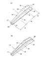
- (A) is the perspective view seen from the vehicle exterior of 1st Example of the mounting apparatus of the vehicle-mounted camera which concerns on this invention
- (b) is the perspective view seen from the vehicle inside back of (a).
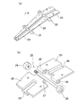
- (A) is a perspective view of the taper plate as a support plate used in the Example of FIG. 1
- (b) is a perspective view of the taper plate seen from the bottom. The perspective view which shows the front-end
- (A) is a perspective view of the modification of a taper plate
- (b) is a perspective view of the decomposition
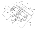
- the perspective view seen from the vehicle exterior front of the 2nd example of the mounting device of the in-vehicle camera concerning the present invention The perspective view seen from the vehicle interior lower side of 3rd Example of the mounting apparatus of the vehicle-mounted camera which concerns on this invention.
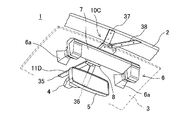
- the perspective view seen from the in-vehicle back of the 4th example of the mounting device of the in-vehicle camera concerning the present invention The perspective view seen from the vehicle exterior front of the 5th Example of the mounting apparatus of the vehicle-mounted camera which concerns on this invention.
- the perspective view seen from the vehicle interior lower side of the mounting apparatus of the vehicle-mounted camera shown in FIG. The perspective view which looked at the modification of the taper plate of FIG. 9 from the vehicle interior downward.
- FIG. 1 is a perspective view of an in-vehicle camera mounting device according to a first embodiment, where (a) is a perspective view seen from outside a vehicle compartment around a position where a rear-view mirror of a vehicle front part is attached, and (b) is a vehicle interior.
- FIG. 2 shows a tapered plate used in FIG. 1, (a) is a perspective view seen from above, and (b) is a perspective view seen from below.
- the vehicle 1 includes a front rail 2 as a vehicle body constituent member extending in the vehicle width direction.
- the front rail 2 extends in a direction perpendicular to the longitudinal axis of the vehicle body, is made of a metal plate having a closed cross section, and is positioned above and behind the windshield.
- a windshield 3 is disposed in front of the front rail 2, and is fixed in a waterproof state with a waterproof member (not shown) sandwiched in an opening at the front of the vehicle body.
- a mirror base 4 is fixed to the windshield 3 by bonding or the like, and a rearview mirror 5 for viewing the rear is attached to the mirror base 4.
- the in-vehicle camera mounting device 10 mounts a camera 6 for photographing the front of the vehicle through the windshield 3 of the vehicle inside the windshield 3.
- the in-vehicle camera of the present embodiment is a stereo camera 6 having a pair of left and right camera parts 6a and 6b, and is attached to both ends of a stay 7 having a predetermined length extending in the direction of the front rail 2, that is, in the vehicle width direction. Two camera parts 6a and 6b are fixed.
- a fixing portion 8 for fixing the stereo camera 6 is formed at the center position of the stay 7.
- the in-vehicle camera mounting device 10 includes a taper plate 11 as a support plate.
- the taper plate 11 is disposed in an inclined state along the windshield 3, and one end thereof is fixed to the front rail 2 located around the windshield. That is, the taper plate 11 is formed of a metal plate extending in the front-rear direction of the vehicle body, and one end portion on the rear side of the vehicle is a first fixing portion 12 fixed to the front rail 2, and the other end portion on the front side of the vehicle. Is a second fixing portion 13 fixed to the windshield 3. And the intermediate part of the taper plate 3 becomes the 3rd fixing
- the second fixing portion 13 is fixed to the mirror base 4 as a receiving member fixed to the windshield 2.
- the taper plate 11 is bent downward at a portion of the first fixing portion 12 at the rear, and when the taper plate 11 is fixed to the front rail 2 by the first fixing portion 12,
- the third fixing portion 14 is configured to be parallel to the windshield 3.
- the taper plate 11 has a first fixing portion 12 fixed to the front rail 2 as a wide parallel portion, and has a taper that gradually decreases in width toward the front side. Since the taper plate 11 is supported at both ends so that the front and rear ends are supported and fixed, it does not require a large strength compared to a cantilevered support member, can be reduced in weight with a simple structure, and is not limited to metal but made of resin. It can also be.
- the taper plate 11 fixes the front rail 2 and the taper plate 11 to the first fixing portion 12 with high accuracy, and fixes the taper plate 11 to the front rail 2.
- a screw hole 16 is formed.
- the second fixing portion 13 on the front end side is formed with a screw hole 17 for fixing a fixing point such as a mirror base 4 installed on the windshield 3 and the front side of the taper plate 11, and the third third portion in the center.
- the fixing portion 14 is formed with a screw hole 18 for fixing the taper plate 11 and the stereo camera 6.
- the stereo camera 6 When the stereo camera 6 tries to correctly recognize the position of a vehicle, a pedestrian, a signal, a sign, etc. in the vehicle traveling direction, the stereo camera 6 is attached to the vehicle as much as possible with an axis parallel to the vehicle traveling direction (hereinafter referred to as the vehicle axis). It is preferable to install the stereo camera 6 with the shooting direction of the stereo camera 6 parallel or shifted by a target angle.
- the direction of the vehicle axis is determined by a hole provided in the front rail 2. Therefore, the shooting direction of the stereo camera 6 can be accurately fixed in a desired direction by fitting the hole prepared in the front rail 2 and the locator pin 15 prepared in the taper plate 11.
- the locator pin 15 is provided on the taper plate 11 side, but a locator pin may be provided on the front rail side and a hole for receiving the locator pin may be provided on the taper plate 11.
- a locator pin may be provided in the second fixing portion 13 fixed to the windshield 3, and a hole for fitting with the locator pin may be provided in the mirror base 4 attached to the windshield 3.
- the taper plate 11 and the third fixing portion 14 of the stereo camera 6 are provided with a locator pin 19 on the taper plate 11 protruding downward, for example, in addition to the screw hole 18 for fixing, so that the stay on the stereo camera 6 side is provided.
- 7 may be provided with a hole for fitting with the locator pin.
- a locator pin may protrude from the fixing portion 8 of the stay 7 to form a hole that fits into the taper plate 11.
- a groove 20 along the longitudinal direction may be provided as shown in FIG.
- a projection having the same shape as the groove 20 as shown in FIG. 2 is also provided on the front rail 2, and the mounting position can be accurately fixed by fitting the groove and the projection.
- the groove and the protrusion may be used as a method of fixing the stereo camera 6 and the taper plate 11 in a desired direction.
- FIG. 3 shows the fixing portion 13 of the taper plate 11 on the windshield 3 side.
- a base for fixing the end is provided on the windshield 3.
- the base may be integrated with the mirror base 4.
- the other end (front end) of the taper plate 11 is fixed by the mirror base 4.
- the design can be enhanced by covering the fixed end with the mirror base 4.
- the stereo camera 6 is fixed to the taper plate 11 to which the front end part was fixed, and the stereo camera 6 images the vehicle traveling direction.
- the stereo camera 6 may be fixed in the direction in which the vehicle interior is photographed.
- the mirror base 4 is fixed to the windshield 3 by adhesion, and the upper surface (contact surface with the windshield 3) 4a (indicated by a two-dot chain parallel oblique line) of the mirror base 4 is tapered.
- a stepped portion 4b into which the tip end portion (the other end portion) of the plate 11 is inserted is formed.
- the taper plate 11 is formed with a groove portion 20 along the longitudinal direction, and a deep portion 4c into which the groove portion 20 is inserted is formed at the center of the step portion 4b.
- the depth of the stepped portion 4 b corresponds to the thickness t of the tapered plate 11, and the depth of the deep portion 4 c corresponds to the thickness T of the groove portion 20.
- the width W of the groove part 20 and the width w of the deep part 4c are formed equally.
- an opening of the stepped portion 4 b and the deep portion 4 c is formed between the lower surface (inner side surface) of the windshield 3 and the upper surface of the mirror base 4, and a tapered plate is formed in this opening. 11 can be inserted.
- the fixing between the mirror base 4 and the taper plate 11 may be by screwing, or the tip of the taper plate 11 may be inserted between the mirror base 4 and the windshield 3 as shown in FIG.
- the tip of the taper plate 11 may be inserted into the stepped portion 4b and the deep portion 4c of the mirror base 4, and a screw may be inserted into the screw hole 17 at the tip of the taper plate 11 to be used together with screwing.
- the taper plate 11 is the vertical fluctuation of the stereo camera 6 caused by the vertical vibration when the vehicle is mounted, and therefore, between the mirror base 4 and the windshield 3 as shown in FIG.
- the taper plate 11 is inserted and fixed with screws using the screw holes 17 provided in the taper plate 11. As shown in FIG. 3B, the tip of the taper plate 11 may be inserted and fixed.
- a method of providing a hole in the mirror base 4 itself and inserting the tip of the taper plate 11 into the hole may be used.
- the fixing of the tip side of the taper plate 11 is shared with the mirror base 4, the mirror base 4 is attached to the windshield 3 and the windshield 3 is attached to the vehicle body.
- one or more plate-side receiving holes are provided to make it a long hole, or in the case of a shape as shown in FIG. By providing the spaces 4d and 4e that allow the positional deviation, the positional deviation can be absorbed without changing the direction of the tapered plate 11.
- the taper plate 11 When the groove part 20 is formed in the taper plate 11 and the groove part 20 is fitted into the deep part 4c in the step part 4b of the mirror base 4, the mirror base 4 and the taper plate 11 are positioned in the left-right direction (vehicle width direction). It is suitable for. Since the taper plate 11 has two fixing points on the front and rear sides, the plate strength can be reduced as compared with the cantilever single point fixing. Therefore, the taper plate 11 may be a sheet metal or a resin. When made of resin, the weight of the plate itself can be reduced, which is more advantageous for vibration.
- the taper plate 11A shown in FIG. 4 includes angle adjusting mechanisms 21 and 22 at two points along the entire length in the longitudinal direction.
- the angle adjustment mechanism is shown schematically.
- the angle adjustment mechanism 22 is installed between the first fixing portion 23 on the front rail 2 side and the intermediate third fixing portion 25 that fixes the stereo camera 6.
- the angle adjusting mechanism 21 is installed between the intermediate third fixing portion 25 and the second fixing portion 24 on the distal end side.
- the angle adjustment mechanism has the same configuration as the hinge mechanism, and can change the angles of the three fixing portions.
- the angle of the windshield differs depending on the vehicle model, and the angle of the bent part of the taper plate needs to be changed accordingly.
- the angle of the windshield of passenger cars has become shallower in order to improve fuel efficiency, and the angle is around 20 degrees.
- the angle of the windshield is deep, and the angle is around 45 degrees.
- the angle adjusting mechanisms 21 and 22 are used so as to be able to cope with all the vehicle types having different angles of the windshields.
- the angle can be adjusted only by the angle adjusting mechanism 21 on the windshield 3 side. However, in order to efficiently place the stereo camera 6 between the windshield 3 and the front rail 2, the angle is also adjusted on the front rail 2 side. It also preferably has a mechanism 22. By using the two angle adjusting mechanisms 21 and 22, the stereo camera 6 can be stably attached in correspondence with the angle and the curved state of the windshield.
- the taper plate 11A having two angle adjusting mechanisms is basically composed of three members. That is, the front end member 24 that is positioned forward and constitutes the second fixing portion, the intermediate member 25 that is positioned in the middle and that constitutes the third fixing portion, and the rear member that is located rearward and constitutes the first fixing portion 23. Since the angle adjustment mechanisms 21 and 22 have substantially the same configuration, the rear angle adjustment mechanism 22 will be described in detail.
- the angle adjustment mechanism 22 connects the intermediate member 25 and the rear member 23 so as to be able to swing, and includes two bearing portions 26 and 26 formed at the front end portion of the rear member 23, and a rear portion of the intermediate member 25. One bearing portion 27 formed at the end portion is connected through a connecting shaft 28.
- a locking nut 29 is screwed onto the tip of the connecting shaft 28, and by tightening the locking nut 29, the bearing portions 26 and 26 of the rear member 23 and the bearing portion 27 of the intermediate member 25 can be fixed at an arbitrary angle. It has a configuration. In the tapered plate 11A configured as described above, even when the angle of the windshield 3 of the vehicle is shallow or deep, it is stable between the front rail 2 and the windshield 3 by adjusting the angle adjusting mechanisms 21 and 22. The vehicle-mounted camera 6 can be attached stably.
- the in-vehicle camera mounting device 10 ⁇ / b> A according to the second embodiment is different from the first embodiment in the shape of the tapered plate.
- symbol is attached
- the taper plate 11B according to the second embodiment has an end portion on the front side of the vehicle that is bifurcated, and two fixing portions 31 and 32 are formed.
- the two fixing portions 31 and 32 are fixed directly to the windshield 3 by bonding or the like, but two bases (not shown) are fixed to the windshield, and the fixed portions 31 and 32 are fixed to the fixed base. 32 may be fixed by screwing or the like.
- the fixed state of the taper plate can be further stabilized by widening the interval between the fixing points on the windshield 3 side, and the stereo camera 6 is also more stably fixed. Further, when the fixed point is separated from the support of the room mirror 5 and the mirror base 4, the mirror base 4 can be disposed away. Furthermore, by expanding the interval between the fixed points, it is possible to reduce displacement with respect to the force applied in the left-right direction on the tip side of the taper plate 11B.
- the in-vehicle camera mounting device 10 ⁇ / b> B of the third embodiment is different from the first and second embodiments in the shape of the first fixing portion on the vehicle rear side of the tapered plate 11 ⁇ / b> C.
- the first fixing portion on the front rail 2 side is formed in a bifurcated manner, and two fixing portions 33 and 34 are formed.
- the fixed state of the taper plate can be further stabilized by widening the interval between the fixing points on the front rail 2 side, and the fixed state of the stereo camera 6 is also more stable. Further, it is possible to arrange the tapered plate 11C while avoiding the illumination and the sunglasses storage part arranged on the front rail 2 side. Furthermore, by increasing the interval between the fixed points, it is possible to reduce the displacement with respect to the force applied in the left-right direction on the rear side of the taper plate 11C.
- the in-vehicle camera mounting device 10 ⁇ / b> C according to the fourth embodiment is different from the other embodiments in the shape of the tapered plate.
- symbol is attached
- the taper plate 11D of the fourth embodiment the end portion on the vehicle front side is formed in a bifurcated portion, two fixing portions 35 and 36 are formed, and the first fixing portion on the vehicle rear side is also formed in a bifurcated portion.
- the two fixing portions 35 and 36 are fixed directly to the furan and the glass 3 by bonding or the like.
- two bases (not shown) are fixed to the windshield, and the fixing portion 35 is fixed to the fixed base. , 36 may be fixed with screws or the like.
- the front and rear end portions of the taper plate are formed in two forks, the front end portion is fixed at two points, and the rear end portion is also fixed at two points, so that the fixed state is more stable.
- the fixed state of the stereo camera 6 is also stabilized. That is, by increasing the interval between the fixed points, the displacement with respect to the force applied in the left-right direction can be reduced. In this case, in FIGS. 5 and 6, when a lateral force is applied to the taper plate, the stereo camera 6 is displaced to be twisted because the front-rear balance is poor.
- the distance between the two fixed points is widened to minimize the displacement of the stereo camera 6 with respect to the left-right direction, and torsion occurs even when the displacement occurs. It is possible to make the structure difficult to do.
- the tapered plate has a shape that takes into account the design.
- FIGS. 8 and 9 when the in-vehicle camera mounting device 10 ⁇ / b> D is viewed from the outside of the passenger compartment through the windshield 3, part or all of the casing excluding the field angle range of the stereo camera 6.
- the taper plate 11E is provided with light-shielding portions 40 and 40 that cover the upper part of the stereo camera.
- the light shielding portions 40, 40 are formed in a rectangular shape extending in the vehicle width direction from the central portion which is a third fixing portion to which the stereo camera 6 is attached.
- the taper plate 11 is disposed on the upper side in the central portion of the stereo camera 6, but when the stereo camera 6 is viewed from outside the passenger compartment, most of the casing shape is visible. Normally, a light shielding area is provided on the windshield 3 side so that the stereo camera 6 cannot be seen from the outside of the passenger compartment. However, in FIGS. The housing of the stereo camera 6 can be covered by the light shielding portions 40 and 40.
- the shading area of the windshield of the vehicle to which the in-vehicle camera is normally attached must be provided so as to avoid the angle of view of the in-vehicle camera, and a different windshield from the vehicle to which the in-vehicle camera is not attached must be used. It is only necessary to provide one type of windshield shading region for each vehicle type.
- the color of the taper plate 11E in FIGS. 8 and 9 is preferably black in order to serve as a light shielding region. Further, since the width of the taper plate 11E is increased, the material may be a resin in order to reduce the weight. Furthermore, since the shape of the taper plate 11E prevents direct sunlight from hitting the stereo camera 6, there is an effect of suppressing an increase in the casing temperature of the stereo camera 6.
- the taper plate may be arranged on the lower side and the side surface of the stereo camera 6 so as to cover the range other than the angle of view of the stereo camera 6 as in the modification of the fifth embodiment shown in FIG.
- a conventional taper plate component can compensate for two components that conventionally required a plate for fixing the stereo camera 6 and a design cover that covers the camera.
- the taper plate 11F shown in FIG. 10 includes a cover portion located below the stereo camera 6.
- the taper plate 11F includes an upper plate portion 41 as a light shielding portion, side plate portions 42 and 42, a lower plate portion 43 as a cover portion, and a rear plate portion 44, and is formed in a box shape having an open front.
- the stereo camera 6 is mounted in a box-shaped taper plate 11F, and is configured to be able to image the traveling direction of the vehicle from the front opening.
- the taper plate 11F is fixed to the front rail 2 with the first fixing portion 12 protruding from the box-shaped rear, and fixed to the mirror base 4 fixed to the windshield 3 with the second fixing portion 13 protruding forward. Is done. Then, the mounting portion 8 of the stay 7 of the stereo camera 6 is fixed to the upper plate portion 41 in the middle of the taper plate 11F, and the camera 6 is mounted and fixed in the box-shaped taper plate.
- the stereo camera 6 can avoid direct sunlight and can improve the appearance in the vehicle by covering the camera.
- the taper plate 11G has a shape in which a vent hole 45 and a vent passage 46 are provided.
- the temperature increase due to direct sunlight may be worse than when the stereo camera 6 is attached to the front rail 2. That is, since the stereo camera 6 is installed and fixed below the windshield 3 in front of the front rail 2, it receives direct sunlight.
- the temperature of the front rail 2 is increased by the direct sunlight being applied to the vehicle, and the temperature of the stereo camera 6 is finally increased through the taper plate. .
- a vent 45 and a vent 46 are provided in the taper plate 11G.
- the cooling air applied to the stereo camera 6 flows along the windshield 3 from below. Therefore, the cooling air can be taken in from the vent 45, and the temperature of the entire tapered plate 11G can be lowered through the vent passage 46.
- the greater the number of vents 45 and vents 46 the greater the cooling effect. Further, the larger the vent 45, the easier the cooling air can be taken.
- the air vent 45 may be directed to the side that receives the cooling wind.
- the vent hole 45 and the vent path 46 the cooling air can be flowed along the taper plate 11G, the temperature rise of the taper plate can be suppressed, and the operation of the stereo camera 6 can be stabilized.
- this invention is not limited to the above-mentioned Example, Various modifications are included.
- the above-described embodiments have been described in detail for easy understanding of the present invention, and are not necessarily limited to those having all the configurations described.
- the bifurcated example is shown as the first fixing portion and the second fixing portion of the taper plate, but it is needless to say that the shape may be three or more.
- Vehicle 2 Front rail 3: Windshield 4: Mirror base (receiving member) 4d, 4e: Space (receiving part) 5: Room mirror 6: Stereo camera (vehicle camera) 7: Stay 8: Stay fixing part 10, 10A, 10B, 10C, 10D, 10E, 10F: On-vehicle camera mounting device 11, 11A, 11B, 11C, 11D, 11E, 11F, 11G: Tapered plate (support plate) 12, 23: First fixing part 13, 24: Second fixing part 14, 25: Third fixing part 16: Front rail fixing screw hole 15: Front rail side positioning locator pin 17: Windshield side fixing Screw hole 18: Stereo camera fixing screw hole 19: Stereo camera positioning locator pin 20: Groove 21: Front rail side angle adjusting mechanism 22: Windshield side angle adjusting mechanism 31, 32, 37, 38: First bifurcated Fixing portions 33, 34, 35, 36: bifurcated second fixing portion 40: light shielding portion 43: cover portion 45: vent 46: air passage
Abstract
Description
以下、本発明に係る車載カメラの取り付け装置の実施例を図面に基づき詳細に説明する。図1は、実施例1に係る車載カメラの取り付け装置を示し、(a)は、車両前部分のルームミラーを取り付ける位置周辺の車室外から見た斜視図であり、(b)は車室内から見た斜視図、図2は図1で使用するテーパープレートを示し、(a)は上方から見た斜視図、(b)は下方から見た斜視図である。
この実施例2の車載カメラの取り付け装置10Aは、図5に示されるように、テーパープレートの形状が実施例1とは異なっている。なお、実施例1と実質的に同一の構成については同じ符号を付して説明を省略する。実施例2のテーパープレート11Bは車両前方側の端部が二股に形成されており、2つの固定部31,32が形成されている。2つの固定部31,32は図示の例ではフロントガラス3に直接接着等で固定されているが、2つのベース(図示せず)をフロントガラスに固定し、固定されたベースに固定部31,32をねじ止め等で固定しても良い。
この実施例3の車載カメラの取り付け装置10Bは、図6に示されるように、テーパープレート11Cの車両後方側の第1の固定部の形状が実施例1,2とは異なっている。テーパープレート11Cはフロントレール2側の第1の固定部が二股に形成され、2つの固定部33,34が形成されている。
この実施例4の車載カメラの取り付け装置10Cは、図7に示されるように、テーパープレートの形状が他の実施例とは異なっている。なお、実施例1と実質的に同一の構成については同じ符号を付して説明を省略する。実施例4のテーパープレート11Dは車両前方側の端部が二股に形成されており、2つの固定部35,36が形成されていると共に、車両後方側の第1の固定部も二股に形成され、固定部37,38が形成されている。2つの固定部35,36は図示の例ではフランとガラス3に直接接着等で固定されているが、2つのベース(図示せず)をフロントガラスに固定し、固定されたベースに固定部35,36をねじ止め等で固定しても良い。
つぎに、車載カメラの取り付け装置の実施例5について、図8,9を参照して説明する。この実施例5では、テーパープレートは意匠性を加味した形状であることを特徴としている。図8,9に示されるように、車載カメラの取り付け装置10Dを車室外からフロントガラス3越しにステレオカメラ6を見た場合に、ステレオカメラ6の画角範囲を除く筐体の一部または全てが隠れるようにテーパープレート11Eは、ステレオカメラの上部を覆う遮光部40,40を備えている。この実施例のテーパープレート11Eでは、遮光部40,40はステレオカメラ6を取り付ける第3の固定部である中央部分から車幅方向に延びる長方形状に形成されている。
つぎに、車載カメラの取り付け装置の実施例6について、図11を参照して説明する。この実施例6の車載カメラの取り付け装置10Fでは、テーパープレート11Gは通気口45と通気路46を設けた形状であることを特徴としている。上述したように、ステレオカメラ6を最適な配置に置いた場合、直射日光による温度上昇は、フロントレール2に取り付けた場合よりも悪化する可能性がある。すなわち、フロントレール2より前方のフロントガラス3の下方にステレオカメラ6は設置固定されるため、日光の直射を受ける。
2:フロントレール
3:フロントガラス
4:ミラーベース(受け部材)
4d,4e:スペース(受け部)
5:ルームミラー
6:ステレオカメラ(車載カメラ)
7:ステー
8:ステーの固定部
10,10A,10B,10C,10D,10E,10F:車載カメラの取り付け装置
11,11A,11B,11C,11D,11E,11F,11G:テーパープレート(支持プレート)
12,23:第1の固定部
13,24:第2の固定部
14,25:第3の固定部
16:フロントレール固定用ねじ孔
15:フロントレール側位置決め用ロケータピン
17:フロントガラス側固定用ねじ孔
18:ステレオカメラ固定用ねじ孔
19:ステレオカメラ位置決め用ロケータピン
20:溝部
21:フロントレール側角度調整機構
22:フロントガラス側角度調整機構
31,32,37,38:二股の第1の固定部
33,34,35,36:二股の第2の固定部
40:遮光部
43:カバー部
45:通気口
46:通気路
Claims (12)
- 車両のフロントガラスを通して車両の前方を撮影する車載カメラをフロントガラスの内側に取り付ける車載カメラの取り付け装置であって、
前記フロントガラスに沿って配置される支持プレートを備え、
前記支持プレートは、一端部が前記フロントガラスの周囲に位置するフロントレールに固定されると共に、その他端部が前記フロントガラスに固定され、
前記車載カメラは、前記支持プレートの中間部に形成された固定部に取り付け固定されることを特徴とする車載カメラの取り付け装置。 - 前記車載カメラは、ステーに支持され、該ステーは、前記支持プレートの固定部に固定されることを特徴とする請求項1に記載の車載カメラの取り付け装置。
- 前記車載カメラは、2つのカメラ部を有するステレオカメラであり、前記ステーは、前記支持プレートの長手方向と直交する方向に長尺でテーパー状に形成され、前記2つのカメラ部は前記ステーの両端部に各々固定されることを特徴とする請求項1に記載の車載カメラの取り付け装置。
- 前記支持プレートの他端部は、前記フロントガラスに固定された受け部材を介して固定されることを特徴とする請求項1に記載の車載カメラの取り付け装置。
- 前記受け部材は、前記支持プレートの設置誤差を吸収する受け部を有することを特徴とする請求項4に記載の車載カメラの取り付け装置。
- 前記支持プレートは、その長手方向に沿って溝部が形成されていることを特徴とする請求項1に記載の車載カメラの取り付け装置。
- 前記支持プレートの他端部は、前記車両のルームミラーの固定部に固定されることを特徴とする請求項1に記載の車載カメラの取り付け装置。
- 前記支持プレートの一端部は、二股あるいは三股以上に形成され、前記フロントレールに固定されることを特徴とする請求項1に記載の車載カメラの取り付け装置。
- 前記支持プレートの他端部は、二股あるいは三股以上に形成され、前記フロントガラスに固定されることを特徴とする請求項1に記載の車載カメラの取り付け装置。
- 前記支持プレートは、前記車載カメラの上部を覆う遮光部を有することを特徴とする請求項1に記載の車載カメラの取り付け装置。
- 前記支持プレートは、前記車載カメラの下部を覆うカバー部を有することを特徴とする請求項1に記載の車載カメラの取り付け装置。
- 前記支持プレートは、通気口及び通気路を有することを特徴とする請求項1に記載の車載カメラの取り付け装置。
Priority Applications (3)
| Application Number | Priority Date | Filing Date | Title |
|---|---|---|---|
| CN201280059226.8A CN103958276B (zh) | 2011-11-30 | 2012-10-24 | 车载摄像机安装装置 |
| DE112012004978.0T DE112012004978B4 (de) | 2011-11-30 | 2012-10-24 | Befestigungsvorrichtung für Fahrzeugkameras |
| US14/352,252 US9344611B2 (en) | 2011-11-30 | 2012-10-24 | Automotive camera mounting apparatus |
Applications Claiming Priority (2)
| Application Number | Priority Date | Filing Date | Title |
|---|---|---|---|
| JP2011-262997 | 2011-11-30 | ||
| JP2011262997A JP5628778B2 (ja) | 2011-11-30 | 2011-11-30 | 車載カメラの取り付け装置 |
Publications (1)
| Publication Number | Publication Date |
|---|---|
| WO2013080706A1 true WO2013080706A1 (ja) | 2013-06-06 |
Family
ID=48535177
Family Applications (1)
| Application Number | Title | Priority Date | Filing Date |
|---|---|---|---|
| PCT/JP2012/077390 WO2013080706A1 (ja) | 2011-11-30 | 2012-10-24 | 車載カメラの取り付け装置 |
Country Status (5)
| Country | Link |
|---|---|
| US (1) | US9344611B2 (ja) |
| JP (1) | JP5628778B2 (ja) |
| CN (1) | CN103958276B (ja) |
| DE (1) | DE112012004978B4 (ja) |
| WO (1) | WO2013080706A1 (ja) |
Cited By (1)
| Publication number | Priority date | Publication date | Assignee | Title |
|---|---|---|---|---|
| CN105346472A (zh) * | 2015-10-22 | 2016-02-24 | 江苏保千里视像科技集团股份有限公司 | 一种车载夜视装置 |
Families Citing this family (33)
| Publication number | Priority date | Publication date | Assignee | Title |
|---|---|---|---|---|
| JP5793122B2 (ja) | 2012-07-31 | 2015-10-14 | 日立オートモティブシステムズ株式会社 | 車載画像処理装置 |
| JP2014178474A (ja) * | 2013-03-14 | 2014-09-25 | Sony Corp | デジタル顕微鏡装置、その合焦位置探索方法およびプログラム |
| KR101698783B1 (ko) * | 2013-12-16 | 2017-01-23 | 엘지전자 주식회사 | 스테레오 카메라 및 이를 구비한 차량 |
| US9876992B2 (en) | 2014-04-30 | 2018-01-23 | Panasonic Intellectual Property Management Co., Ltd. | Imaging apparatus and distance measuring apparatus using the same |
| JP6518907B2 (ja) * | 2014-09-09 | 2019-05-29 | 株式会社ユピテル | 車載機器 |
| JP2016107755A (ja) * | 2014-12-04 | 2016-06-20 | 日本板硝子株式会社 | ウインドシールド及び車載システム |
| JP2016113142A (ja) * | 2014-12-15 | 2016-06-23 | 株式会社リコー | 移動体用カメラ及びカメラを搭載した移動体 |
| JP6268085B2 (ja) | 2014-12-24 | 2018-01-24 | 株式会社東海理化電機製作所 | 撮像装置 |
| US9744907B2 (en) * | 2014-12-29 | 2017-08-29 | Gentex Corporation | Vehicle vision system having adjustable displayed field of view |
| JP2016126243A (ja) * | 2015-01-07 | 2016-07-11 | 株式会社リコー | カメラ装置 |
| DE102015200943A1 (de) * | 2015-01-21 | 2016-07-21 | Conti Temic Microelectronic Gmbh | Sensormodul |
| KR101724299B1 (ko) | 2015-02-04 | 2017-04-07 | 엘지전자 주식회사 | 트리플 카메라 |
| KR101724300B1 (ko) | 2015-02-04 | 2017-04-07 | 엘지전자 주식회사 | 스테레오 카메라 |
| KR101655814B1 (ko) * | 2015-02-10 | 2016-09-08 | 엘지전자 주식회사 | 차량의 리어뷰 미러 일체형 전방 카메라 모듈 |
| JP6202028B2 (ja) * | 2015-03-24 | 2017-09-27 | トヨタ自動車株式会社 | 周辺情報検出センサの配設構造及び自動運転車両 |
| US10144424B2 (en) | 2015-04-09 | 2018-12-04 | Toyota Jidosha Kabushiki Kaisha | Arrangement structure for vicinity information detection sensor |
| JP6421691B2 (ja) | 2015-04-28 | 2018-11-14 | 株式会社デンソー | カメラ装置 |
| JP6507835B2 (ja) * | 2015-05-14 | 2019-05-08 | スズキ株式会社 | 車載機器用カバー構造 |
| JP6304205B2 (ja) * | 2015-11-11 | 2018-04-04 | トヨタ自動車株式会社 | 車載撮像装置 |
| KR101822894B1 (ko) * | 2016-04-07 | 2018-01-29 | 엘지전자 주식회사 | 차량 운전 보조 장치 및 차량 |
| JP6771762B2 (ja) * | 2016-10-25 | 2020-10-21 | 株式会社ユピテル | 機器 |
| JP7364233B2 (ja) * | 2016-10-25 | 2023-10-18 | 株式会社ユピテル | 機器 |
| EP3690805A4 (en) | 2017-09-28 | 2021-09-29 | Koito Manufacturing Co., Ltd. | SENSOR SYSTEM |
| JP7020844B2 (ja) * | 2017-09-29 | 2022-02-16 | 株式会社デンソー | 車載カメラ装置 |
| JP6976136B2 (ja) * | 2017-10-26 | 2021-12-08 | 京セラ株式会社 | カメラブラケット、撮像装置および移動体 |
| JP6922706B2 (ja) * | 2017-12-06 | 2021-08-18 | トヨタ自動車株式会社 | センサー搭載構造 |
| TWM563372U (zh) * | 2018-02-01 | 2018-07-11 | 雄鉅實業有限公司 | 具l形固定裝置的電子裝置 |
| JP7143636B2 (ja) * | 2018-06-01 | 2022-09-29 | 株式会社デンソー | 撮像装置 |
| JP2020037342A (ja) * | 2018-09-05 | 2020-03-12 | 三菱電機株式会社 | 車載用カメラ装置 |
| JP7211292B2 (ja) * | 2019-06-28 | 2023-01-24 | トヨタ自動車株式会社 | 車両構造 |
| JP7240639B2 (ja) * | 2019-09-26 | 2023-03-16 | いすゞ自動車株式会社 | カメラカバー取付構造 |
| DE102019132479A1 (de) * | 2019-11-29 | 2021-06-02 | Bayerische Motoren Werke Aktiengesellschaft | Innenrückspiegel für ein Kraftfahrzeug und Kraftfahrzeug |
| US11738698B1 (en) | 2022-04-28 | 2023-08-29 | Argo AI, LLC | Mounting device for maintaining rigid alignment between cameras |
Citations (5)
| Publication number | Priority date | Publication date | Assignee | Title |
|---|---|---|---|---|
| JPH03266739A (ja) * | 1990-03-15 | 1991-11-27 | Aisin Seiki Co Ltd | 車載撮像装置 |
| JP2001088623A (ja) * | 1999-09-22 | 2001-04-03 | Fuji Heavy Ind Ltd | 車載カメラの取付構造 |
| JP2007015457A (ja) * | 2005-07-05 | 2007-01-25 | Fuji Heavy Ind Ltd | 車載機器の防熱構造 |
| JP2009280195A (ja) * | 2008-04-25 | 2009-12-03 | Fuji Heavy Ind Ltd | ステレオカメラユニット |
| JP2010526700A (ja) * | 2007-05-10 | 2010-08-05 | ヴァレオ・シャルター・ウント・ゼンゾーレン・ゲーエムベーハー | 車両用機能ユニットの固定装置 |
Family Cites Families (9)
| Publication number | Priority date | Publication date | Assignee | Title |
|---|---|---|---|---|
| DE19647200C1 (de) | 1996-11-15 | 1998-01-08 | Kostal Leopold Gmbh & Co Kg | Gehäuse für Dachmodul |
| JPH1178717A (ja) * | 1997-09-13 | 1999-03-23 | Honda Motor Co Ltd | 車両搭載カメラ |
| US6445287B1 (en) * | 2000-02-28 | 2002-09-03 | Donnelly Corporation | Tire inflation assistance monitoring system |
| JP3619173B2 (ja) | 2001-07-03 | 2005-02-09 | 三菱電機株式会社 | 車載カメラ装置 |
| DE10162652A1 (de) * | 2001-12-20 | 2003-07-03 | Bosch Gmbh Robert | Stereo-Kamera-Anordnung in einem Kraftfahrzeug |
| US8256821B2 (en) * | 2004-12-15 | 2012-09-04 | Magna Donnelly Engineering Gmbh | Accessory module system for a vehicle window |
| JP2009068906A (ja) * | 2007-09-11 | 2009-04-02 | Panasonic Corp | 距離測定装置 |
| JP2011109634A (ja) * | 2009-06-17 | 2011-06-02 | Rohm Co Ltd | 車載カメラ |
| US20120081550A1 (en) * | 2010-10-04 | 2012-04-05 | Tk Holdings Inc. | Camera system |
-
2011
- 2011-11-30 JP JP2011262997A patent/JP5628778B2/ja active Active
-
2012
- 2012-10-24 WO PCT/JP2012/077390 patent/WO2013080706A1/ja active Application Filing
- 2012-10-24 DE DE112012004978.0T patent/DE112012004978B4/de active Active
- 2012-10-24 US US14/352,252 patent/US9344611B2/en active Active
- 2012-10-24 CN CN201280059226.8A patent/CN103958276B/zh active Active
Patent Citations (5)
| Publication number | Priority date | Publication date | Assignee | Title |
|---|---|---|---|---|
| JPH03266739A (ja) * | 1990-03-15 | 1991-11-27 | Aisin Seiki Co Ltd | 車載撮像装置 |
| JP2001088623A (ja) * | 1999-09-22 | 2001-04-03 | Fuji Heavy Ind Ltd | 車載カメラの取付構造 |
| JP2007015457A (ja) * | 2005-07-05 | 2007-01-25 | Fuji Heavy Ind Ltd | 車載機器の防熱構造 |
| JP2010526700A (ja) * | 2007-05-10 | 2010-08-05 | ヴァレオ・シャルター・ウント・ゼンゾーレン・ゲーエムベーハー | 車両用機能ユニットの固定装置 |
| JP2009280195A (ja) * | 2008-04-25 | 2009-12-03 | Fuji Heavy Ind Ltd | ステレオカメラユニット |
Cited By (1)
| Publication number | Priority date | Publication date | Assignee | Title |
|---|---|---|---|---|
| CN105346472A (zh) * | 2015-10-22 | 2016-02-24 | 江苏保千里视像科技集团股份有限公司 | 一种车载夜视装置 |
Also Published As
| Publication number | Publication date |
|---|---|
| DE112012004978B4 (de) | 2019-07-04 |
| JP2013112314A (ja) | 2013-06-10 |
| DE112012004978T5 (de) | 2014-08-28 |
| US9344611B2 (en) | 2016-05-17 |
| CN103958276A (zh) | 2014-07-30 |
| JP5628778B2 (ja) | 2014-11-19 |
| US20140247390A1 (en) | 2014-09-04 |
| CN103958276B (zh) | 2016-11-16 |
Similar Documents
| Publication | Publication Date | Title |
|---|---|---|
| JP5628778B2 (ja) | 車載カメラの取り付け装置 | |
| EP3054348B1 (en) | Stereo camera for a vehicle | |
| JP5851009B2 (ja) | 車載カメラの取り付け装置 | |
| JP6970276B2 (ja) | 鞍乗型車両 | |
| EP1086859B1 (en) | Structure for mounting cameras on a vehicle | |
| KR101655814B1 (ko) | 차량의 리어뷰 미러 일체형 전방 카메라 모듈 | |
| JP5646924B2 (ja) | ドライブレコーダ | |
| JP6578856B2 (ja) | カメラ取付部の構造 | |
| KR101533911B1 (ko) | 차량, 특히 상용 차량을 위한 가시 시스템 | |
| US10780828B2 (en) | Sensor mount structure | |
| JP7172682B2 (ja) | カメラ搭載構造 | |
| WO2011132344A1 (ja) | カメラユニット取付方法及びカメラユニット | |
| KR102123496B1 (ko) | 센서 탑재 구조 | |
| JP6967659B2 (ja) | 鞍乗型車両 | |
| US20190170545A1 (en) | Sensor mount structure | |
| JP2004082829A (ja) | 車載カメラ | |
| US20190375344A1 (en) | Bracket and sensor device | |
| US20210364631A1 (en) | Vehicle sensor mounting structure and vehicle sensor bracket set | |
| JP2001088611A (ja) | 車載カメラ | |
| JP5632967B2 (ja) | 車両搭載カメラ | |
| JP5488202B2 (ja) | 車載カメラ | |
| JP2014169072A (ja) | 視認システムおよびそれを装備された車両 | |
| JP5260398B2 (ja) | カメラ配置構造 | |
| JP2014216731A (ja) | 車両用室内灯ユニット | |
| BR102017015761B1 (pt) | Tampa de dobradiça para uma porta de veículo e veículo comercial |
Legal Events
| Date | Code | Title | Description |
|---|---|---|---|
| 121 | Ep: the epo has been informed by wipo that ep was designated in this application |
Ref document number: 12853203 Country of ref document: EP Kind code of ref document: A1 |
|
| WWE | Wipo information: entry into national phase |
Ref document number: 14352252 Country of ref document: US |
|
| WWE | Wipo information: entry into national phase |
Ref document number: 112012004978 Country of ref document: DE Ref document number: 1120120049780 Country of ref document: DE |
|
| 122 | Ep: pct application non-entry in european phase |
Ref document number: 12853203 Country of ref document: EP Kind code of ref document: A1 |