WO2013077080A1 - 紫外線硬化型樹脂組成物、及びその硬化物の剥離方法 - Google Patents
紫外線硬化型樹脂組成物、及びその硬化物の剥離方法 Download PDFInfo
- Publication number
- WO2013077080A1 WO2013077080A1 PCT/JP2012/074802 JP2012074802W WO2013077080A1 WO 2013077080 A1 WO2013077080 A1 WO 2013077080A1 JP 2012074802 W JP2012074802 W JP 2012074802W WO 2013077080 A1 WO2013077080 A1 WO 2013077080A1
- Authority
- WO
- WIPO (PCT)
- Prior art keywords
- acrylate
- meth
- curable resin
- resin composition
- ultraviolet curable
- Prior art date
- Legal status (The legal status is an assumption and is not a legal conclusion. Google has not performed a legal analysis and makes no representation as to the accuracy of the status listed.)
- Ceased
Links
Images


Classifications
-
- C—CHEMISTRY; METALLURGY
- C08—ORGANIC MACROMOLECULAR COMPOUNDS; THEIR PREPARATION OR CHEMICAL WORKING-UP; COMPOSITIONS BASED THEREON
- C08G—MACROMOLECULAR COMPOUNDS OBTAINED OTHERWISE THAN BY REACTIONS ONLY INVOLVING UNSATURATED CARBON-TO-CARBON BONDS
- C08G18/00—Polymeric products of isocyanates or isothiocyanates
- C08G18/06—Polymeric products of isocyanates or isothiocyanates with compounds having active hydrogen
- C08G18/70—Polymeric products of isocyanates or isothiocyanates with compounds having active hydrogen characterised by the isocyanates or isothiocyanates used
- C08G18/72—Polyisocyanates or polyisothiocyanates
- C08G18/74—Polyisocyanates or polyisothiocyanates cyclic
- C08G18/75—Polyisocyanates or polyisothiocyanates cyclic cycloaliphatic
- C08G18/751—Polyisocyanates or polyisothiocyanates cyclic cycloaliphatic containing only one cycloaliphatic ring
- C08G18/752—Polyisocyanates or polyisothiocyanates cyclic cycloaliphatic containing only one cycloaliphatic ring containing at least one isocyanate or isothiocyanate group linked to the cycloaliphatic ring by means of an aliphatic group
- C08G18/753—Polyisocyanates or polyisothiocyanates cyclic cycloaliphatic containing only one cycloaliphatic ring containing at least one isocyanate or isothiocyanate group linked to the cycloaliphatic ring by means of an aliphatic group containing one isocyanate or isothiocyanate group linked to the cycloaliphatic ring by means of an aliphatic group having a primary carbon atom next to the isocyanate or isothiocyanate group
- C08G18/755—Polyisocyanates or polyisothiocyanates cyclic cycloaliphatic containing only one cycloaliphatic ring containing at least one isocyanate or isothiocyanate group linked to the cycloaliphatic ring by means of an aliphatic group containing one isocyanate or isothiocyanate group linked to the cycloaliphatic ring by means of an aliphatic group having a primary carbon atom next to the isocyanate or isothiocyanate group and at least one isocyanate or isothiocyanate group linked to a secondary carbon atom of the cycloaliphatic ring, e.g. isophorone diisocyanate
-
- C—CHEMISTRY; METALLURGY
- C08—ORGANIC MACROMOLECULAR COMPOUNDS; THEIR PREPARATION OR CHEMICAL WORKING-UP; COMPOSITIONS BASED THEREON
- C08F—MACROMOLECULAR COMPOUNDS OBTAINED BY REACTIONS ONLY INVOLVING CARBON-TO-CARBON UNSATURATED BONDS
- C08F290/00—Macromolecular compounds obtained by polymerising monomers on to polymers modified by introduction of aliphatic unsaturated end or side groups
- C08F290/02—Macromolecular compounds obtained by polymerising monomers on to polymers modified by introduction of aliphatic unsaturated end or side groups on to polymers modified by introduction of unsaturated end groups
- C08F290/06—Polymers provided for in subclass C08G
- C08F290/067—Polyurethanes; Polyureas
-
- C—CHEMISTRY; METALLURGY
- C08—ORGANIC MACROMOLECULAR COMPOUNDS; THEIR PREPARATION OR CHEMICAL WORKING-UP; COMPOSITIONS BASED THEREON
- C08F—MACROMOLECULAR COMPOUNDS OBTAINED BY REACTIONS ONLY INVOLVING CARBON-TO-CARBON UNSATURATED BONDS
- C08F299/00—Macromolecular compounds obtained by interreacting polymers involving only carbon-to-carbon unsaturated bond reactions, in the absence of non-macromolecular monomers
- C08F299/02—Macromolecular compounds obtained by interreacting polymers involving only carbon-to-carbon unsaturated bond reactions, in the absence of non-macromolecular monomers from unsaturated polycondensates
- C08F299/06—Macromolecular compounds obtained by interreacting polymers involving only carbon-to-carbon unsaturated bond reactions, in the absence of non-macromolecular monomers from unsaturated polycondensates from polyurethanes
- C08F299/065—Macromolecular compounds obtained by interreacting polymers involving only carbon-to-carbon unsaturated bond reactions, in the absence of non-macromolecular monomers from unsaturated polycondensates from polyurethanes from polyurethanes with side or terminal unsaturations
-
- C—CHEMISTRY; METALLURGY
- C08—ORGANIC MACROMOLECULAR COMPOUNDS; THEIR PREPARATION OR CHEMICAL WORKING-UP; COMPOSITIONS BASED THEREON
- C08G—MACROMOLECULAR COMPOUNDS OBTAINED OTHERWISE THAN BY REACTIONS ONLY INVOLVING UNSATURATED CARBON-TO-CARBON BONDS
- C08G18/00—Polymeric products of isocyanates or isothiocyanates
- C08G18/06—Polymeric products of isocyanates or isothiocyanates with compounds having active hydrogen
- C08G18/28—Polymeric products of isocyanates or isothiocyanates with compounds having active hydrogen characterised by the compounds used containing active hydrogen
- C08G18/40—High-molecular-weight compounds
- C08G18/48—Polyethers
- C08G18/4825—Polyethers containing two hydroxy groups
-
- C—CHEMISTRY; METALLURGY
- C08—ORGANIC MACROMOLECULAR COMPOUNDS; THEIR PREPARATION OR CHEMICAL WORKING-UP; COMPOSITIONS BASED THEREON
- C08G—MACROMOLECULAR COMPOUNDS OBTAINED OTHERWISE THAN BY REACTIONS ONLY INVOLVING UNSATURATED CARBON-TO-CARBON BONDS
- C08G18/00—Polymeric products of isocyanates or isothiocyanates
- C08G18/06—Polymeric products of isocyanates or isothiocyanates with compounds having active hydrogen
- C08G18/28—Polymeric products of isocyanates or isothiocyanates with compounds having active hydrogen characterised by the compounds used containing active hydrogen
- C08G18/67—Unsaturated compounds having active hydrogen
- C08G18/671—Unsaturated compounds having only one group containing active hydrogen
- C08G18/672—Esters of acrylic or alkyl acrylic acid having only one group containing active hydrogen
-
- C—CHEMISTRY; METALLURGY
- C09—DYES; PAINTS; POLISHES; NATURAL RESINS; ADHESIVES; COMPOSITIONS NOT OTHERWISE PROVIDED FOR; APPLICATIONS OF MATERIALS NOT OTHERWISE PROVIDED FOR
- C09J—ADHESIVES; NON-MECHANICAL ASPECTS OF ADHESIVE PROCESSES IN GENERAL; ADHESIVE PROCESSES NOT PROVIDED FOR ELSEWHERE; USE OF MATERIALS AS ADHESIVES
- C09J4/00—Adhesives based on organic non-macromolecular compounds having at least one polymerisable carbon-to-carbon unsaturated bond ; adhesives, based on monomers of macromolecular compounds of groups C09J183/00 - C09J183/16
Definitions
- the present invention relates to an ultraviolet curable resin composition useful for peeling a layer formed by curing an ultraviolet curable resin composition present on the surface of an optical substrate and a method for peeling the cured product.
- This touch panel has a structure in which a display device, a glass plate or a resin film on which a transparent electrode is formed, and a glass or resin transparent protective plate are bonded together.
- a glass plate on which a display device and transparent electrodes are formed is very expensive. Therefore, after bonding the substrate with the UV curable resin composition, if the bubbles or the bonding position are wrong, it is necessary to return the substrate to the state before bonding and re-paste. is there.
- the UV curable resin cured product layer is cut, the cured product layer is softened by adding a solvent, the cured product layer is removed from the substrate with a brush, and finally the surface is wiped with a solvent. The material is restored.
- the present invention relates to an ultraviolet curable resin composition capable of recovering an optical substrate with good productivity from an optical member bonded with an ultraviolet curable resin with little damage to the optical substrate, and a method for peeling the cured product.
- the purpose is to provide.
- the present invention relates to the following (1) to (12).
- Step 1 In the ultraviolet curable resin composition used in the method including the following (Step 1) to (Step 3) for peeling a layer formed by curing an ultraviolet curable resin composition present on the surface of an optical substrate.
- An ultraviolet curable resin composition comprising (meth) acrylate (A) and a photopolymerization initiator (B).
- Step 2 The process which makes the base material for peeling contact the layer formed by hardening
- Step 2 A step of attaching a layer formed by curing the ultraviolet curable resin composition to the substrate for peeling.
- Step 3 An optical substrate and ultraviolet rays are peeled off from the optical substrate by attaching and collecting a layer formed by curing the ultraviolet curable resin composition on the peeling substrate to the surface of the peeling substrate. The process of peeling the layer formed by hardening
- the (meth) acrylate (A) is at least one (meth) acrylate selected from the group consisting of urethane (meth) acrylate, (meth) acrylate having a polyisoprene skeleton, and a (meth) acrylate monomer.
- the ultraviolet curable resin composition according to (1) comprising: (3)
- the (meth) acrylate (A) is a urethane (meth) acrylate, and the urethane (meth) acrylate is obtained by reacting a polyol, a polyisocyanate and a hydroxyl group-containing (meth) acrylate. ) Acrylate, wherein the polyol is at least one selected from the group consisting of polyethylene glycol, polypropylene glycol, polytetramethylene glycol, ethylene oxide-modified bisphenol A, propylene oxide-modified bisphenol A, and polyester polyol.
- the urethane (meth) acrylate (A) is urethane (meth) acrylate, and urethane (meth) acrylate is obtained by reacting polypropylene glycol, polyisocyanate and hydroxyl group-containing (meth) acrylate (The ultraviolet curable resin composition according to (3), which is a (meth) acrylate.
- the (meth) acrylate is a (meth) acrylate monomer, and the (meth) acrylate is lauryl (meth) acrylate, 2-ethylhexyl carbitol acrylate, acryloylmorpholine, 4-hydroxybutyl (meth) acrylate, tetrahydro It is one or more selected from the group consisting of furfuryl (meth) acrylate, isostearyl (meth) acrylate, polypropylene oxide-modified nonylphenyl (meth) acrylate, and dicyclopentenyloxyethyl (meth) acrylate ( The ultraviolet curable resin composition as described in 2).
- (Process 1) The process which makes the base material for peeling contact the layer formed by hardening
- (Step 2) A step of attaching a layer formed by curing the ultraviolet curable resin composition to the substrate for peeling.
- An optical substrate and ultraviolet rays are peeled off from the optical substrate by attaching and collecting a layer formed by curing the ultraviolet curable resin composition on the peeling substrate to the surface of the peeling substrate. The process of peeling the layer formed by hardening
- the ultraviolet curable resin composition is an ultraviolet curable resin composition containing (meth) acrylate (A) and a photopolymerization initiator (B), and (meth) acrylate (A) is a polyol, Urethane (meth) acrylate obtained by reacting polyisocyanate and hydroxyl group-containing (meth) acrylate, wherein the polyol is polyethylene glycol, polypropylene glycol, polytetramethylene glycol, ethylene oxide modified bisphenol A, propylene oxide modified
- the peeling method according to (6) or (7), wherein the peeling method is one or more selected from the group consisting of bisphenol A and polyester polyol.
- the ultraviolet curable resin composition is an ultraviolet curable resin composition containing (meth) acrylate (A) and a photopolymerization initiator (B), and (meth) acrylate (A) is lauryl ( (Meth) acrylate, 2-ethylhexyl carbitol acrylate, acryloylmorpholine, 4-hydroxybutyl (meth) acrylate, tetrahydrofurfuryl (meth) acrylate, isostearyl (meth) acrylate, polypropylene oxide modified nonylphenyl (meth) acrylate, dicyclo
- the peeling method according to any one of (6) to (8), wherein the peeling method is at least one selected from the group consisting of pentenyloxyethyl (meth) acrylates.
- the optical substrate is one or more selected from the group consisting of a transparent glass substrate, a transparent resin substrate, a glass substrate with a touch sensor, a liquid crystal display unit, a plasma display unit, and an organic EL display unit.
- the base material for peeling is at least one selected from the group consisting of a metal roll, a resin roll, a metal substrate, a resin substrate, and a resin film. The peeling method as described in any one of 10).
- (12) Prior to (Step 1), a layer obtained by curing the ultraviolet curable resin composition present on the surface of the optical substrate is obtained by irradiating with ultraviolet rays at an irradiation dose of 10 to 1000 mJ / cm 2.
- the optical base material there is little damage to the optical base material, and the optical base material can be recovered economically with good productivity.
- FIG. 1 is a view showing an optical member to which the peeling method of the present invention can be applied
- FIG. 2 is a process of peeling a layer formed by curing the ultraviolet curable resin composition of the present invention from the surface of the optical substrate. It is process drawing which shows 1st Embodiment.
- the optical member has a configuration in which the same or different optical base materials are bonded to both surfaces of a cured resin layer made of an ultraviolet curable resin composition.
- Various materials can be used as the optical substrate. Specifically, PET, PC, PMMA, composite of PC and PMMA, glass, COC, COP, plastic (acrylic resin, etc.), polarizing plate, lens sheet A prism sheet, ITO glass, or the like can be used.
- the following sheets, display bodies, and optical functional materials can be used.
- the sheet include an icon sheet, a decorative sheet, and a protective sheet
- examples of the plate include a decorative board and a protective plate.
- or board what was enumerated as a material of a transparent board is applicable.
- Examples of the display body include display devices such as LCD, EL display, EL illumination, electronic paper, and plasma display in which a polarizing plate is attached to glass.
- Examples of the optical functional material include transparent plastic plates such as acrylic plates, PC plates, PET plates, and PEN plates, tempered glass, and touch panel input sensors.
- a layer formed by curing an ultraviolet curable resin composition from an optical member in which a liquid crystal display unit 1 and a glass substrate 2 having a touch sensor are bonded as an optical substrate (hereinafter referred to as a resin)
- the method will be described based on a method of peeling 3) (also referred to as a cured product layer).
- the liquid crystal display unit 1 is a liquid crystal display unit in which a liquid crystal material is sealed between a pair of substrates on which electrodes are formed, and a polarizing plate, a driving circuit, a signal input cable, and a backlight unit are provided.
- the glass substrate 2 having a touch sensor has a transparent electrode formed on the surface of the glass substrate.
- the resin cured product layer 3 is made of a cutting member such as a wire 4 smaller than the thickness of the resin cured product layer 3, and the blade of the cutting member contacts the surface of the optical substrate. Do not cut, saw, or shear.
- a known member can be used without any particular problem as long as it is thinner than the cured resin layer 3 and can cut the cured resin layer.
- a wire, a fine wire, a cutter, a knife, a saw, or the like can be used.
- any method may be used as long as the cured resin layer 3 can be cut. Specifically, there are a cutting method and a drawing method.
- the cured resin layer 3 is a layer obtained by curing a resin, and includes not only a layer that is entirely cured but also a layer that is semi-cured with a cured portion and an uncured portion. .
- Examples of the semi-cured layer include those in which only a specific portion of the layer is intensively cured and the remainder is uncured.
- cured material layer is formed with respect to the optical base material bonded together, and the method of peeling off are also mentioned,
- cured material layer 3 is semi-hardened.
- a method of applying a force and peeling off as described above can be applied as a cutting method.
- the base material for peeling is made to contact the layer 3 formed by hardening
- a metal roll 5 is used as the peeling substrate and brought into contact with the surface of the cured resin layer 3.
- Cylindrical metal materials such as iron, steel, zinc, titanium, aluminum, copper, alloys such as stainless steel and brass, or plastic materials such as PET, PC, PMMA, and a composite of PC and PMMA.
- Spherical shape, prismatic shape, plate shape, film shape and the like can be used.
- a metal roll, a resin roll, a glass roll, a metal substrate, a resin substrate, and the like can be used.
- an easy-adhesive film when a plate-like or film-like shape is used, an easy-adhesive film can be suitably used.
- Easy-adhesion films include polypropylene film, fluororesin film, polyphenylene sulfide film, polyester film, polyethylene naphthalate film, PET film, polyvinylidene chloride film, and corona discharge to improve the adhesion to the resin.
- surface activation treatment such as treatment or plasma treatment, processing treatment for forming irregularities, and those subjected to coating treatment with an adhesive layer containing a polymer binder can be preferably used.
- those having transparency in the ultraviolet region can be suitably used.
- the cured resin layer 3 can be adhered to the peeling substrate by ultraviolet irradiation in step 2.
- a film that does not undergo the above surface treatment to a film such as a polypropylene film, a fluororesin film, a polyphenylene sulfide film, a polyester film, a polyethylene naphthalate film, a PET film, or a polyvinyl chloride film.
- a film such as a polypropylene film, a fluororesin film, a polyphenylene sulfide film, a polyester film, a polyethylene naphthalate film, a PET film, or a polyvinyl chloride film.
- adding flexibility by adding a softening agent is preferable because adhesion can be easily made to a cured portion or an uncured portion of the cured resin layer 3. It is.
- the softening agent to be added for example, a fatty acid derivative or the like can be used.
- the polyvinylidene chloride film obtained by adding a softening agent to the resin include saran wrap (manufactured by Asahi Kasei Chemical Co., Ltd.), clerap (manufactured by Kureha Co., Ltd.), and Riken wrap (manufactured by Riken Technos Co., Ltd.).
- the film thickness of the easily adhesive film is preferably 1 to 100 ⁇ m, particularly preferably 5 to 20 ⁇ m.
- the peeling substrate is subjected to a surface treatment.
- the processing treatment include an uneven portion on the surface of the material, and a coating treatment that coats the surface of the peeling substrate with an easy-adhesive film.
- the unevenness formed by the processing is preferably fine, and macroscopic unevenness having a height of several ⁇ m to several tens of ⁇ m and a pitch of several tens of ⁇ m to several hundreds of ⁇ m is formed on the surface. It is particularly preferable.
- an easily adhesive film used for coating treatment in order to improve the adhesion to the resin on the surface of films such as polypropylene film, fluororesin film, polyphenylene sulfide film, polyester film, polyethylene naphthalate film, PET film, etc.
- films such as polypropylene film, fluororesin film, polyphenylene sulfide film, polyester film, polyethylene naphthalate film, PET film, etc.
- Those subjected to surface activation treatment such as corona discharge treatment and plasma treatment, processing treatments for forming irregularities, and those subjected to coating treatment with an adhesive layer containing a polymer binder can be preferably used.
- the surface of the peeling substrate is applied by applying a corrosion inhibitor or the like so that the peeling substrate can be recycled. It is preferable to use a substrate for peeling which has been etched.
- curing an ultraviolet curable resin composition is made to adhere to a base material for peeling.
- the metal roll 5 and the surface of the cured resin layer 3 are adhered to each other by, for example, applying a pressure 6 to the metal roll 5.
- the method for attaching the cured resin layer 3 to the peeling substrate include a method of heating, a method of heating, a method of irradiating with ultraviolet rays, and the like. Further, even if these methods are not adopted, the cured resin layer 3 adheres to the peeling substrate to some extent by allowing the peeling substrate and the cured resin layer 3 to come into contact with each other.
- process 2 since the contact is an adhesion process (process 2), (process 2) is also achieved by performing (process 1).
- a method of irradiating with ultraviolet rays is preferably used.
- the layer 3 formed by curing the ultraviolet curable resin composition on the peeling substrate is attached to the surface of the peeling substrate and collected from the optical substrate.
- the optical base material and the layer 3 formed by curing the ultraviolet curable resin composition are peeled off.
- the resin cured product is adhered to a portion where the resin cured product is not adhered, thereby peeling off. Go. That is, the cured resin layer 3 is peeled off from the optical base material by using the rotation of the metal roll 5.
- the cured resin layer 3 sticks to the peeling base material so as to be caught by the peeling base material.
- the substrate is peeled off in a form in which the resin is adhered to the peeling substrate by pulling it up in the peeling direction.
- the resin cured material layer 3 can be removed by employ
- the cured resin layer 3 can be peeled from the optical substrate.
- the cured resin layer 3 can be effectively removed from the optical substrate by peeling the cured resin layer 3 from the optical substrate.
- the optical substrate thus obtained can be used as an optical substrate to be bonded to obtain an optical member again.
- the optical base material which removed the resin cured material layer 3 in order to obtain the optical base material with few deposits by the resin cured material layer 3, it is preferable to go through the process of wiping a base material with an organic solvent.
- organic solvent examples include alcohols such as methanol, ethanol and isopropanol, ketones such as acetone and methyl ethyl ketone, and aliphatic solvents such as hexane and heptane.
- the peeling method of the present invention automatically removes the cured resin from the peeling substrate by a machine by introducing the peeling substrate into the optical member manufacturing apparatus in the removal process that has been performed by the work of a conventional person. Since it is realizable, the manufacturing efficiency of an optical member can be improved significantly and the number of workers can be reduced. Furthermore, it is possible to make the process of using the solvent only the process of wiping the substrate, so it is possible to reduce the amount of the solvent used, which is economical, low cost, and low environmental impact. It is possible to perform a repair process (repair process) including In addition, since the number of separation steps is small, the time required for the repair step can be reduced.
- an ultraviolet curable resin composition is applied to an optical substrate, and at least two optical substrates are bonded together, and then irradiated with ultraviolet rays to obtain an optical member.
- a coating material such as a slit coater, a roll coater, a spin coater, or a screen printing method is applied to one substrate so that the thickness of the applied resin is 10 to 300 ⁇ m. It is performed by applying and bonding the other substrate.
- the optical member obtained in this way it is inspected whether or not defects caused by bonding, such as air bubbles intervening between the optical substrate and the cured resin layer 3, are detected. In the inspection, the presence or absence of a defect is judged. If there is a defect, the cured resin layer 3 is removed from the optical substrate by the peeling method of the present invention.
- the amount of UV irradiation suitable for peeling the cured resin layer 3 from the optical substrate is usually 10 to 2000 mJ / cm 2 , preferably 10 to 1000 mJ / cm 2 , particularly preferably 50 to 500 mJ / cm 2. Degree. If it is less than 10 mJ / cm 2, the cured resin layer 3 is difficult to adhere to the substrate for peeling, and if it is more than 2000 mJ / cm 2 , the cured product layer 3 may be difficult to peel from the substrate.
- any light source may be used as long as it is a lamp that emits ultraviolet to near ultraviolet rays.
- a low-pressure, high-pressure or ultrahigh-pressure mercury lamp, metal halide lamp, (pulse) xenon lamp, or electrodeless lamp can be used.
- the irradiation dose here is usually 10 to 2000 mJ / cm 2 , preferably 10 to 2000 mJ / cm 2 , and particularly preferably about 50 to 500 mJ / cm 2 . If it is less than 10 mJ / cm 2, the cured resin layer 3 may be difficult to adhere to the substrate for peeling, and if it is more than 2000 mJ / cm 2 , it may be difficult to peel off.
- any light source may be used as long as it is a lamp that emits ultraviolet to near ultraviolet rays.
- a low-pressure, high-pressure or ultrahigh-pressure mercury lamp, metal halide lamp, (pulse) xenon lamp, or electrodeless lamp can be used.
- the entire surface of the cured resin layer 3 may be irradiated with ultraviolet rays, or a method of intensively irradiating several portions of the cured resin layer 3 may be employed.
- a method of irradiating several places intensively it is preferable to irradiate opposite points or sides on the optical base material because the optical base material can be fixed by temporary curing. Specifically, there is a method of irradiating two opposing corners or two sides.
- a method of intensively irradiating the four corners of the bonded optical base material or a method of intensively irradiating the four sides of the optical base material is based on temporary curing. It can be suitably applied to ensure the fixation of the optical substrate. By doing so, it becomes possible to obtain the semi-cured resin cured product layer 3.
- an uncured resin surface composed of a cured portion obtained by intensive irradiation after temporary curing and an uncured portion with insufficient irradiation can be formed.
- the irradiation dose in this step is usually 500 to 5000 mJ / cm 2 , preferably about 1000 to 5000 mJ / cm 2 .
- the cured resin layer 3 is removed from the optical base material by performing the separation steps (Step 1) to (Step 3), and the optical material from which the deposits are removed.
- the substrate will be used again to obtain the optical member.
- the process scheme for obtaining the optical member in which the peeling method of the present invention can be used is not limited to the above process, and for example, defect inspection before temporary curing may be omitted. In that case, inspection is performed after a series of steps from application of resin to provisional curing.
- the UV curable resin composition of the present invention is applied to one substrate using a coating device such as a slit coater, roll coater, spin coater, screen printing method, etc. Is applied so that the thickness becomes 10 to 300 ⁇ m, the other base material is bonded, and the transparent base material side is irradiated with ultraviolet rays to near ultraviolet rays (wavelength of 200 to 400 nm) and cured. it can.
- the amount of UV irradiation suitable for peeling the cured resin layer 3 from the optical substrate is preferably 10 to 1000 mJ / cm 2 , particularly preferably about 50 to 500 mJ / cm 2 .
- any light source may be used as long as it is a lamp that emits ultraviolet to near ultraviolet rays.
- a low-pressure, high-pressure or ultrahigh-pressure mercury lamp, metal halide lamp, (pulse) xenon lamp, or electrodeless lamp can be used.
- FIG. 4 is a process diagram showing a second embodiment of a process of peeling the layer 3 formed by curing the ultraviolet curable resin composition of the present invention from the surface of the optical substrate.
- symbol is attached
- the base material for peeling is made to contact the layer 3 formed by hardening
- a resin film 7 is used as a peeling substrate, and is brought into contact with the surface of the cured resin layer 3.
- the layer 3 formed by curing the ultraviolet curable resin composition on the peeling substrate is attached to the surface of the peeling substrate and collected from the optical substrate.
- the optical base material and the layer 3 formed by curing the ultraviolet curable resin composition are peeled off.
- the cured resin layer 3 is peeled from the optical base material by pulling up the cured resin layer 3 in a direction in which the resin film adhered to the surface of the resin film is peeled off.
- the cured resin layer 3 can be peeled from the optical substrate.
- FIG. 5 is a process diagram showing a third embodiment of the process of peeling the layer 3 formed by curing the ultraviolet curable resin composition of the present invention from the surface of the optical substrate.
- symbol is attached
- cured material layer 3 forms the resin cured material layer 3 semi-hardened so that it may have a hardened part and an unhardened part with respect to the optical base material bonded together. Apply force in the opposite direction to the direction that is being peeled off and split.
- the base material for peeling is made to contact the layer 3 formed by semi-hardening an ultraviolet curable resin composition.
- a resin film 7 is used as a peeling substrate, and is brought into contact with the surface of the cured resin layer 3.
- the layer 3 formed by semi-hardening an ultraviolet curable resin composition is made to adhere to a peeling base material. Specifically, the resin film 7 and the surface of the cured resin layer 3 are attached by curing the uncured portion by irradiating the ultraviolet ray 8 to the semi-cured layer 3.
- the layer 3 formed by curing the ultraviolet curable resin composition on the peeling substrate is attached to the surface of the peeling substrate and collected from the optical substrate.
- the optical base material and the layer 3 formed by curing the ultraviolet curable resin composition are peeled off.
- the cured resin layer 3 is peeled from the optical base material by pulling up the cured resin layer 3 in a direction in which the resin film adhered to the surface of the resin film is peeled off.
- the cured resin layer 3 can be peeled from the optical substrate.
- the ultraviolet curable resin of the present invention contains (meth) acrylate (A) and a photopolymerization initiator (B).
- (meth) acrylate (A) urethane (meth) acrylate, (meth) acrylate having a polyisoprene skeleton, (meth) acrylate monomer, and the like can be used.
- Urethane (meth) acrylate is obtained by reacting polyhydric alcohol, polyisocyanate and hydroxyl group-containing (meth) acrylate.
- an ultraviolet curable resin composition containing urethane (meth) acrylate as the resin cured product layer for the optical member, the resin cured product layer can be easily removed when the peeling process of the present invention is applied. It can be attached to the material. That is, the cured resin layer is non-fragmented (continuously) without leaving fragments or lumps as a residue of the cured resin layer on the optical substrate by adhering in pieces to the peeling substrate. In particular, it can be suitably used in the peeling process of the present invention.
- polyhydric alcohol examples have 1 to 10 carbon atoms such as neopentyl glycol, 3-methyl-1,5-pentanediol, ethylene glycol, propylene glycol, 1,4-butanediol, 1,6-hexanediol, etc.
- polyhydric alcohols and polybasic acids for example, succinic acid, triol such as alkylene glycol, trimethylolpropane, pentaerythritol, alcohols having a cyclic skeleton such as tricyclodecane dimethylol, bis- [hydroxymethyl] -cyclohexane, etc.
- polyester polyol obtained by reaction with polyhydric alcohol and ⁇ -caprolactone Alcohol
- polycarbonate polyol for example, polycarbonate diol obtained by reaction of 1,6-hexanediol and diphenyl carbonate
- polyether polyol for example, polyethylene glycol, polypropylene glycol, polytetramethylene glycol, ethylene oxide modified bisphenol A, etc.
- Polypropylene glycol is preferable from the viewpoint of compatibility and adhesion, and polypropylene glycol having a molecular weight of 2000 or more is particularly preferable from the viewpoint of adhesion to the substrate.
- polypropylene glycol having a molecular weight of 2000 or more is used, the adhesive strength of the cured product layer is improved, and therefore, when two or more optical substrates are bonded, the prevention of peeling due to external pressure or environmental changes is improved. Is preferable.
- organic polyisocyanate examples include isophorone diisocyanate, hexamethylene diisocyanate, tolylene diisocyanate, xylene diisocyanate, diphenylmethane-4,4'-diisocyanate, and dicyclopentanyl isocyanate.
- hydroxyl group-containing (meth) acrylates include hydroxy C2-C4 alkyl (meth) acrylates such as hydroxyethyl (meth) acrylate, hydroxypropyl (meth) acrylate, hydroxybutyl (meth) acrylate, dimethylol cyclohexyl mono ( A (meth) acrylate, a hydroxycaprolactone (meth) acrylate, a hydroxyl group terminal polyalkylene glycol (meth) acrylate, etc. can be used.
- hydroxy C2-C4 alkyl (meth) acrylates such as hydroxyethyl (meth) acrylate, hydroxypropyl (meth) acrylate, hydroxybutyl (meth) acrylate, dimethylol cyclohexyl mono ( A (meth) acrylate, a hydroxycaprolactone (meth) acrylate, a hydroxyl group terminal polyalkylene glycol (meth) acryl
- the reaction is performed, for example, as follows. That is, the polyhydric alcohol is mixed with an organic polyisocyanate per equivalent of the hydroxyl group so that the isocyanate group is preferably 1.1 to 2.0 equivalent, more preferably 1.1 to 1.5 equivalent. Is preferably reacted at 70 to 90 ° C. to synthesize a urethane oligomer. Next, the hydroxy (meth) acrylate compound is mixed so that the hydroxyl group is preferably 1 to 1.5 equivalents per equivalent of the isocyanate group of the urethane oligomer, and reacted at 70 to 90 ° C. to react with the target urethane (meth). ) Acrylate can be obtained.
- the weight average molecular weight of urethane (meth) acrylate is preferably about 7,000 to 25,000, and more preferably 10,000 to 20,000. When the weight average molecular weight is less than 7000, shrinkage increases, and when the weight average molecular weight is more than 25,000, curability may be poor.
- urethane (meth) acrylates can be used alone or in admixture of two or more.
- the weight ratio of urethane (meth) acrylate in the ultraviolet curable resin composition of the present invention is usually 20 to 80% by weight, preferably 30 to 70% by weight.
- the (meth) acrylate having a polyisoprene skeleton has a (meth) acryloyl group at the terminal or side chain of the polyisoprene molecule.
- a (meth) acrylate having a polyisoprene skeleton can be obtained as “UC-203” (manufactured by Kuraray Co., Ltd.).
- the weight ratio of the (meth) acrylate having a polyisoprene skeleton in the ultraviolet curable resin composition of the present invention is usually 20 to 80% by weight, preferably 30 to 70% by weight.
- a (meth) acrylate having one (meth) acryloyl group in the molecule can be preferably used.
- isooctyl (meth) acrylate, isoamyl (meth) acrylate can be used.
- Alkyl (meth) acrylates having 5 to 20 carbon atoms such as lauryl (meth) acrylate, isodecyl (meth) acrylate, stearyl (meth) acrylate, cetyl (meth) acrylate, isomyristyl (meth) acrylate, tridecyl (meth) acrylate, etc.
- alkyl (meth) acrylates having 10 to 20 carbon atoms, 2-ethylhexyl carbitol acrylate, acryloylmorpholine, 4-hydroxybutyl (meth) acrylate, tetrahydrofurfuryl (meth) acrylate, isostearyl (meth) acrylate, dicyclo Pentenyloxyethyl (meth) acrylate and polypropylene oxide-modified nonylphenyl (meth) acrylate are preferred.
- alkyl (meth) acrylate having 10 to 20 carbon atoms, dicyclopentenyloxyethyl (meth) Preferred are acrylate, polypropylene oxide-modified nonylphenyl (meth) acrylate, and tetrahydrofurfuryl (meth) acrylate.
- an alkyl (meth) acrylate having 1 to 5 carbon atoms having a hydroxyl group and acryloylmorpholine are preferable, and acryloylmorpholine is particularly preferable.
- the (meth) acrylate monomer refers to (meth) acrylate excluding urethane (meth) acrylate, epoxy (meth) acrylate, and (meth) acrylate having a polyisoprene skeleton.
- composition of the present invention can contain a (meth) acrylate monomer other than (meth) acrylate having one (meth) acryloyl group as long as the characteristics of the present invention are not impaired.
- a (meth) acrylate monomer other than (meth) acrylate having one (meth) acryloyl group for example, tricyclodecane dimethylol di (meth) acrylate, dioxane glycol di (meth) acrylate, polypropylene glycol di (meth) acrylate, polytetramethylene glycol di (meth) acrylate, alkylene oxide modified bisphenol A type di (meth) acrylate Trimethylol C2-C10 alkanes such as caprolactone-modified hydroxypivalic acid neopentyl glycol di (meth) acrylate and ethylene oxide-modified phosphoric acid di (meth) acrylate, trimethylolpropane tri (meth) acrylate, tri
- (meth) acrylate having a propylene oxide skeleton it is particularly preferable to use (meth) acrylate having a propylene oxide skeleton, from the viewpoint of adhesiveness to the substrate for peeling in Step 2. That is, when a (meth) acrylate having a propylene oxide skeleton is used, the adhesive force to the substrate for peeling is improved, and thus it is preferable to peel off the cured product layer from the optical substrate in Step 3, which is preferable. .
- the (meth) acrylate having a propylene oxide skeleton include polypropylene glycol (meth) acrylate, polypropylene oxide-modified nonylphenyl (meth) acrylate, polypropylene glycol di (meth) acrylate, and propylene oxide-modified trimethylolpropane tri (meth).
- An acrylate is mentioned.
- isooctyl (meth) acrylate isoamyl (meth) acrylate, lauryl (meth) acrylate, isodecyl (meth) acrylate, stearyl (meth) acrylate, cetyl C5-C20 alkyl (meth) acrylates such as (meth) acrylate, isomyristyl (meth) acrylate, tridecyl (meth) acrylate, dicyclopentenyl acrylate, dicyclopentenyloxyethyl (meth) acrylate, isobornyl (meth) Acrylate, dicyclopentanyl (meth) acrylate, 1-adamantyl acrylate, 2-methyl-2-adamantyl acrylate, 2-ethyl-2-adamantyl acrylate, 1-adamantyl methacrylate DOO, polypropylene oxide modified nony
- these (meth) acrylate monomer components can be used alone or in admixture of two or more at any ratio.
- the weight ratio of the (meth) acrylate monomer in the ultraviolet curable resin composition of the present invention is usually 5 to 70% by weight, preferably 10 to 50% by weight. If it is less than 5% by weight, the curability may be poor, and if it is more than 70% by weight, shrinkage may increase.
- Examples of the photopolymerization initiator (B) contained in the ultraviolet curable resin composition of the present invention include 1-hydroxycyclohexyl phenyl ketone (Irgacure 184; manufactured by BASF), 2-hydroxy-2-methyl- [4- ( 1-methylvinyl) phenyl] propanol oligomer (Esacure ONE; manufactured by Lamberti), 1- [4- (2-hydroxyethoxy) -phenyl] -2-hydroxy-2-methyl-1-propan-1-one (Irgacure 2959; manufactured by BASF), 2-hydroxy-1- ⁇ 4- [4- (2-hydroxy-2-methyl-propionyl) -benzyl] -phenyl ⁇ -2-methyl-propan-1-one (Irgacure 127; Manufactured by BASF), 2,2-dimethoxy-2-phenylacetophenone (Irgacure 651; manufactured by BASF), -Hydroxy-2-methyl-1-phenyl-
- these photopolymerization initiators can be used alone or in admixture of two or more at any ratio.
- the weight ratio of the photopolymerization initiator in the ultraviolet curable resin composition of the present invention is usually 0.2 to 5% by weight, preferably 0.3 to 3% by weight.
- amines that can serve as photopolymerization initiation assistants can be used in combination with the above photopolymerization initiator.
- examples of amines that can be used include benzoic acid 2-dimethylaminoethyl ester, dimethylaminoacetophenone, p-dimethylaminobenzoic acid ethyl ester, and p-dimethylaminobenzoic acid isoamyl ester.
- the content in the ultraviolet curable resin composition of the present invention is usually 0.005 to 5% by weight, preferably 0.01 to 3% by weight.
- epoxy (meth) acrylate can be used as long as the characteristics of the present invention are not impaired.
- Epoxy (meth) acrylate has a function of improving curability and improving the hardness and curing speed of a cured product. Any epoxy (meth) acrylate can be used as long as it is obtained by reacting a glycidyl ether type epoxy compound with (meth) acrylic acid, and preferably used epoxy (meth) acrylate.
- Examples of the glycidyl ether type epoxy compound to be obtained include diglycidyl ether of bisphenol A or its alkylene oxide adduct, diglycidyl ether of bisphenol F or its alkylene oxide adduct, diglycidyl of hydrogenated bisphenol A or its alkylene oxide adduct.
- Diglycidyl ether ethylene glycol diglycidyl ether, propylene glycol diglycidyl ether of ether, hydrogenated bisphenol F or its alkylene oxide adduct Neopentyl glycol diglycidyl ether, butanediol diglycidyl ether hexanediol diglycidyl ether to, cyclohexanedimethanol diglycidyl ether, and polypropylene glycol diglycidyl ether.
- Epoxy (meth) acrylate is obtained by reacting these glycidyl ether type epoxy compounds with (meth) acrylic acid under the following conditions.
- (Meth) acrylic acid is preferably reacted at a ratio of 0.9 to 1.5 mol, more preferably 0.95 to 1.1 mol, per 1 equivalent of epoxy group of the glycidyl ether type epoxy compound.
- the reaction temperature is preferably 80 to 120 ° C., and the reaction time is about 10 to 35 hours.
- a catalyst such as triphenylphosphine, TAP, triethanolamine, or tetraethylammonium chloride.
- paramethoxyphenol, methylhydroquinone or the like can be used as a polymerization inhibitor.
- An epoxy (meth) acrylate that can be suitably used in the present invention is a bisphenol A type epoxy (meth) acrylate obtained from a bisphenol A type epoxy compound.
- the weight average molecular weight of the epoxy (meth) acrylate is preferably 500 to 10,000.
- the weight ratio of the epoxy (meth) acrylate in the ultraviolet curable resin composition of the present invention is usually 1 to 80% by weight, preferably 5 to 30% by weight.
- a compound having a structure represented by the general formula (1) can be contained as necessary.
- n represents an integer of 0 to 40
- m represents an integer of 10 to 50.
- R 1 and R 2 may be the same or different.
- R 1 and R 2 each have 1 to 18 alkyl groups, alkenyl groups having 1 to 18 carbon atoms, alkynyl groups having 1 to 18 carbon atoms, and aryl groups having 5 to 18 carbon atoms.
- the weight ratio of the compound having the structure represented by the general formula (1) in the ultraviolet curable resin composition is usually 10 to 80% by weight, preferably 10 to 70% by weight.
- a softening component can be used in the ultraviolet curable resin composition of the present invention as necessary.
- Specific examples of the softening component that can be used include polyisoprene, (meth) acrylate oligomer having a polybutadiene skeleton or esterified product thereof, polymer, oligomer, phthalate ester, phosphate ester, glycol ester, citrate ester Aliphatic dibasic acid esters, fatty acid esters, epoxy plasticizers, castor oils, terpene hydrogenated resins, and the like.
- Examples of oligomers and polymers include polyisoprene-based, polybutadiene-based, and xylene-based oligomers or polymers.
- the weight ratio of the softening component in the ultraviolet curable resin composition is usually 10 to 80% by weight, preferably 10 to 70% by weight.
- an antioxidant In the ultraviolet curable resin composition of the present invention, an antioxidant, an organic solvent, a silane coupling agent, a polymerization inhibitor, a leveling agent, an antistatic agent, a surface lubricant, a fluorescent whitening agent, and a light stabilizer are optionally added. You may add additives, such as an agent (for example, hindered amine compound etc.) and a filler.
- an agent for example, hindered amine compound etc.
- antioxidants include, for example, BHT, 2,4-bis- (n-octylthio) -6- (4-hydroxy-3,5-di-t-butylanilino) -1,3,5-triazine Pentaerythrityl tetrakis [3- (3,5-di-t-butyl-4-hydroxyphenyl) propionate], 2,2-thio-diethylenebis [3- (3,5-di-t-butyl- 4-hydroxyphenyl) propionate], triethylene glycol-bis [3- (3-tert-butyl-5-methyl-4-hydroxyphenyl) propionate], 1,6-hexanediol-bis [3- (3-t -Butyl-5-methyl-4-hydroxyphenyl) propionate], octadecyl-3- (3,5-di-t-butyl-4-hydroxyphenyl) propionate, , N-hexamethylenebis (3,5-di-di
- organic solvent examples include alcohols such as methanol, ethanol and isopropyl alcohol, dimethyl sulfone, dimethyl sulfoxide, tetrahydrofuran, dioxane, toluene, xylene and the like.
- silane coupling agent examples include, for example, 3-glycidoxypropyltrimethoxysilane, 3-glycidoxypropylmethyldimethoxysilane, 3-glycidoxypropylmethyldimethoxysilane, 2- (3,4-epoxy) (Cyclohexyl) ethyltrimethoxysilane, N- (2-aminoethyl) 3-aminopropylmethyldimethoxysilane, ⁇ -mercapropropyltrimethoxysilane, N- (2-aminoethyl) 3-aminopropylmethyltrimethoxysilane, 3 -Aminopropyltriethoxysilane, 3-mercaptopropyltrimethoxysilane, vinyltrimethoxysilane, N- (2- (vinylbenzylamino) ethyl) 3-aminopropyltrimethoxysilane hydrochloride, 3-methacryloxypropyltri
- polymerization inhibitor examples include paramethoxyphenol and methylhydroquinone.
- the light stabilizer include, for example, 1,2,2,6,6-pentamethyl-4-piperidyl alcohol, 2,2,6,6-tetramethyl-4-piperidyl alcohol, 1,2,2, 6,6-pentamethyl-4-piperidyl (meth) acrylate (LA-82, manufactured by ADEKA Corporation), tetrakis (1,2,2,6,6-pentamethyl-4-piperidyl) -1,2,3 4-butanetetracarboxylate, tetrakis (2,2,6,6-totramethyl-4-piperidyl) -1,2,3,4-butanetetracarboxylate, 1,2,3,4-butanetetracarboxylic acid and 1,2,2,6,6-pentamethyl-4-piperidinol and 3,9-bis (2-hydroxy-1,1-dimethylethyl) -2,4,8,10-tetraoxaspiro [5.5] Unde Mixed ester with decanoic acid bis (2,2,6,6-tetramethyl-4-
- the filler include, for example, crystalline silica, fused silica, alumina, zircon, calcium silicate, calcium carbonate, silicon carbide, silicon nitride, boron nitride, zirconia, fosterite, steatite, spinel, titania, talc and the like.
- examples thereof include powder or beads obtained by spheroidizing these.
- the weight ratio of the various additives in the ultraviolet curable resin composition is usually 0.01 to 3% by weight, preferably 0.01 to 1% by weight, more preferably 0.02 to 0.5% by weight.
- the ultraviolet curable resin composition of the present invention can be obtained by mixing and dissolving the aforementioned components at room temperature to 80 ° C., and if necessary, impurities may be removed by an operation such as filtration.
- impurities may be removed by an operation such as filtration.
- the cure shrinkage of the cured product of the ultraviolet curable resin composition of the present invention is preferably 3.0% or less, and particularly preferably 2.0% or less.
- the transmittance at 400 nm to 800 nm of the cured product of the ultraviolet curable resin composition of the present invention is preferably 90% or more.
- the transmittance at 400 to 450 nm is preferably 90% or more.
- the ultraviolet curable resin composition of the present invention can be suitably used as an adhesive for laminating a plurality of optical substrates.
- the optical substrate having a light shielding part can be used without particular limitation as long as the light shielding part is formed on the surface of the optical substrate made of the above material.
- the optical base material to be bonded to the optical base material having the light shielding material may have a light shielding portion on the surface or may not have the light shielding material.
- the ultraviolet curable resin composition of this invention can be used also as an adhesive agent which bonds a sheet
- examples of the sheet include an icon sheet, a decorative sheet, and a protective sheet
- examples of the plate include a decorative board and a protective plate.
- or board what was enumerated as a material of a transparent board is applicable.
- the material for the touch panel surface include glass, PET, PC, PMMA, a composite of PC and PMMA, COC, and COP.
- the ultraviolet curable resin composition of the present invention can also be suitably used for bonding a display unit of a liquid crystal display device and an optical substrate.
- the display unit include LCD, EL display, EL illumination, electronic paper, plasma display, and other display devices in which a polarizing plate is attached to glass.
- the optical functional material include transparent plastic plates such as acrylic plates, PC plates, PET plates, and PEN plates, tempered glass, and touch panel input sensors.
- the refractive index of the cured product is preferably 1.45 to 1.55 in order to improve visibility.
- the difference in refractive index from the base material used as the optical base material can be reduced, and the light loss can be reduced by suppressing the irregular reflection of light.
- An optical member including a display unit and an optical base material bonded together with the ultraviolet curable resin composition of the present invention can be incorporated into an electronic device such as a television, a small game machine, a mobile phone, and a personal computer.
- UV curable resin compositions having the compositions shown in Table 1 were prepared.
- each component shown with the abbreviation in Table 1 is as follows.
- ACMO acryloylmorpholine
- 4-HBA 4-hydroxybutyl acrylate manufactured by Kojin Co., Ltd.
- LA lauryl acrylate manufactured by Osaka Organic Chemical Industry Co., Ltd.
- FA-512AS manufactured by Osaka Organic Chemical Industry Co., Ltd .
- THFA Tetrahydrofurfuryl acrylate, Osaka Organic Chemical Industry Co., Ltd.
- M-117 Propylene oxide 2.5 mol modified nonylphenyl acrylate, Toa Gosei Co., Ltd.
- NP-5P Propylene oxide 5 mol modified nonylphenyl acrylate, Daiichi Kogyo Seiyaku Co., Ltd.
- speed cure TPO 2,4,6-trimethylbenzoyldiphenylphosphine oxide, manufactured by LAMBSON
- each obtained ultraviolet curable resin composition of the present invention was produced.
- Production of Optical Member Having Resin Cured Material Layer of the Present Invention Each ultraviolet curable resin composition of Examples 1 to 5 prepared in a 3.5 inch liquid crystal display unit was applied so as to have a film thickness of 250 ⁇ m.
- a glass substrate having a touch sensor was placed on each ultraviolet curable resin composition and bonded to a liquid crystal display unit.
- an ultraviolet ray of 200 mJ / cm 2 is irradiated from the glass substrate side having the touch sensor with an ultra-high pressure mercury lamp (TOSCURE 752, manufactured by Harrison Toshiba Lighting Co., Ltd.), the cured resin layer is cured, and the optical member of the present invention is used.
- TOSCURE 752 ultra-high pressure mercury lamp
- the cured resin layer 3 was cut using a metal wire 4 to separate the liquid crystal display unit 1 and the glass substrate 2 having a touch sensor. .
- Example 6 As shown in FIG. 2 (b), a metal roll (material: stainless steel, shape: cylindrical shape, dimension: bottom diameter 5 cm, axial length 10 cm) 5 is a cured resin layer 3 on the liquid crystal display unit 1. And the cured resin layer 3 on the glass substrate 2 having the touch sensor. Next, as shown in FIG. 2 (c), pressure 6 was applied to the metal roll 5 to adhere the metal roll 5 and the surface of the cured resin layer 3. Finally, as shown in FIG. 2D, the metal roll 5 was rotated, and the cured resin layer 3 was peeled off.
- a metal roll material: stainless steel, shape: cylindrical shape, dimension: bottom diameter 5 cm, axial length 10 cm
- Example 7 As shown in FIG. 4B, the resin film (material: PET) 7 is brought into contact with the cured resin layer 3 on the liquid crystal display unit 1 and the cured resin layer 3 on the glass substrate 2 having the touch sensor. did. Next, as shown in FIG. 4C, pressure 6 was applied to the resin film 7 to adhere the resin film 7 and the surface of the cured resin layer 3. Finally, as shown in FIG. 4D, the resin film 7 was pulled up from the end, and the cured resin layer 3 was peeled off.
- material material: PET
- the glass substrate 2 having the liquid crystal display unit 1 and the touch sensor after the cured resin layer 3 was peeled off was washed with isopropanol, and the surface was visually observed. Both were the same as the surface state before bonding.
- FIG. 4A the cured resin layer 3 is cut using a metal wire 4, and the liquid crystal display unit 1 and the glass substrate 2 having the touch sensor are separated, and then FIG.
- a resin film (material: PET) 7 was brought into contact with the cured resin layer 3 on the liquid crystal display unit 1 and the cured resin layer 3 on the glass substrate 2 having a touch sensor.
- FIG. 4C pressure 6 was applied to the resin film 7 to adhere the resin film 7 and the surface of the cured resin layer 3.
- FIG. 4 (d) the resin film 7 is pulled up from the end, the cured resin layer 3 is peeled off, and the cured resin adhered to the resinous film 7 and the glass substrate 2. The condition was observed.
- UV-curable resin composition A 0.8 mm thick slide glass and an 0.8 mm thick acrylic plate were bonded together so that the film thickness of the obtained UV-curable resin composition was 200 ⁇ m, and a high-pressure mercury lamp ( A sample for evaluation was prepared by irradiating with 2000 mJ / cm 2 of ultraviolet rays at 80 W / cm, ozone-less). This was allowed to stand for 250 hours in an environment of 85 ° C. and 85% RH, and peeling was confirmed visually. However, the ultraviolet curable resin compositions described in Examples 1 to 5 did not peel.
- the obtained ultraviolet curable resin composition was sufficiently cured, measured for durometer E hardness according to JIS K7215, and evaluated for flexibility.
- the ultraviolet curable resin described in Examples 1 to 5 The value was less than 10 in the composition.
- Transparency Two glass slides each having a thickness of 1 mm coated with a fluorine-based release agent were bonded so that the film thickness of the obtained ultraviolet curable resin composition was 200 ⁇ m, and a high-pressure mercury lamp (80 W through the glass). / Cm, ozone-less) was irradiated with ultraviolet rays of 2000 mJ / cm 2 to prepare a cured product for transparency measurement. Transparency was determined by measuring the transmittance at 400 to 800 nm and 400 to 450 nm using a spectrophotometer (U-3310, Hitachi High-Technologies Corporation), and in the ultraviolet curable resin compositions described in Examples 1 to 5. The transmittance at 400 to 800 nm was 90% or more and the transmittance at 400 to 450 nm was 90% or more.
- Example 8 As shown in FIG. 5 (a), the cured product layer 3 is formed on the optical base material bonded to the resin cured product layer 3 semi-cured so as to have a cured portion and an uncured portion. A force was applied in the direction opposite to the direction in which it was peeled off. Then, as shown in FIG.5 (b), the resin-made film (material: polyvinylidene chloride) 7 is made into the resin cured material layer 3 which exists on a liquid crystal display unit, and the resin cured material layer which exists on the glass substrate 2 which has a touch sensor. 3 was contacted. Next, as shown in FIG.
- the uncured portion was cured by irradiating ultraviolet rays 8, and the resin film 7 and the surface of the cured resin layer 3 were adhered. Finally, as shown in FIG. 5 (d), the resin film 7 was pulled up from the end, and the cured resin layer 3 was peeled off.
- the glass substrate having the liquid crystal display unit and the touch sensor after peeling off the cured resin layer 3 was washed with isopropanol, and the surface was visually observed. Then, it was the same as the surface state before bonding.
- An optical member of the present invention having a cured resin layer 3 that is semi-cured to have And as shown to Fig.5 (a), the hardened
- the resin cured material (material: polyvinylidene chloride) 7 is placed on the liquid crystal display unit 1 as shown in FIG.
- the cured resin layer 3 on the glass substrate 2 having the layer 3 and the touch sensor was brought into contact. Next, as shown in FIG.
- the resin film 7 and the cured resin layer 3 surface were adhered by curing the uncured portion by irradiation.
- FIG. 5 (d) the resin film 7 is pulled up from the end, the cured resin layer 3 is peeled off, and the cured resin adhered to the resinous film 7 and the glass substrate 2. The condition was observed. The peelability was evaluated according to the following criteria, and the results were as shown in Table 3.
- the ultraviolet curable resin composition of the present invention can be suitably used for laminating an optical base material for producing an optical member, etc., and the optical member having the laminated structure has little damage to the optical base material and is optically highly productive. The substrate can be restored.
- SYMBOLS 1 Liquid crystal display unit 2 Glass substrate which has a touch sensor, 3 Resin hardened material layer, 4 Wire, 5 Metal roll, 6 Pressure, 7 Resin film, 8 Ultraviolet
Landscapes
- Chemical & Material Sciences (AREA)
- Organic Chemistry (AREA)
- Health & Medical Sciences (AREA)
- Chemical Kinetics & Catalysis (AREA)
- Medicinal Chemistry (AREA)
- Polymers & Plastics (AREA)
- Adhesives Or Adhesive Processes (AREA)
- Macromonomer-Based Addition Polymer (AREA)
- Devices For Indicating Variable Information By Combining Individual Elements (AREA)
- Paints Or Removers (AREA)
- Laminated Bodies (AREA)
Abstract
Description
また、ハケで硬化物層を基材から除去するには、通常溶剤を使用するため、コスト及び環境負荷がかかるだけでなく、従来の方法では装置に組み込むことにより自動化を達成することができない工程となることから、時間、人員が多く必要となるという問題を有していた。
(工程1)剥離用基材を、紫外線硬化型樹脂組成物を硬化してなる層に接触させる工程。
(工程2)紫外線硬化型樹脂組成物を硬化してなる層を剥離用基材に付着させる工程。
(工程3)剥離用基材に紫外線硬化型樹脂組成物を硬化してなる層を剥離基材の表面に付着させて捕集することにより光学基材から剥離させることで、光学基材と紫外線硬化型樹脂組成物を硬化してなる層を剥離していく工程。
(2)前記(メタ)アクリレート(A)が、ウレタン(メタ)アクリレート、ポリイソプレン骨格を有する(メタ)アクリレート、(メタ)アクリレートモノマーからなる群から選ばれる1種以上の(メタ)アクリレートであるからなることを特徴とする(1)に記載の紫外線硬化型樹脂組成物。
(3)前記(メタ)アクリレート(A)がウレタン(メタ)アクリレートであって、ウレタン(メタ)アクリレートが、ポリオール、ポリイソシアネート及びヒドロキシル基含有(メタ)アクリレートを反応させることによって得られるウレタン(メタ)アクリレートであって、ポリオールが、ポリエチレングリコール、ポリプロピレングリコール、ポリテトラメチレングリコール、エチレンオキサイド変性ビスフェノールA、プロピレンオキサイド変性ビスフェノールA、ポリエステルポリオールからなる群から選ばれる1種以上であることを特徴とする(1)~(2)のいずれか一項に記載の紫外線硬化型樹脂組成物。
(4)前記(メタ)アクリレート(A)がウレタン(メタ)アクリレートであって、ウレタン(メタ)アクリレートが、ポリプロピレングリコール、ポリイソシアネート及びヒドロキシル基含有(メタ)アクリレートを反応させることによって得られるウレタン(メタ)アクリレートである(3)に記載の紫外線硬化型樹脂組成物。
(5)前記(メタ)アクリレートが(メタ)アクリレートモノマーであって、(メタ)アクリレートが、ラウリル(メタ)アクリレート、2-エチルヘキシルカルビトールアクリレート、アクリロイルモルホリン、4-ヒドロキシブチル(メタ)アクリレート、テトラヒドロフルフリル(メタ)アクリレート、イソステアリル(メタ)アクリレート、ポリプロピレンオキサイド変性ノニルフェニル(メタ)アクリレート、ジシクロペンテニルオキシエチル(メタ)アクリレートからなる群から選ばれる1種以上であることを特徴とする(2)に記載の紫外線硬化型樹脂組成物。
(6)(工程1)~(工程3)を有する方法による光学基材表面に存在する紫外線硬化型樹脂組成物を硬化してなる層を剥離する剥離方法。
(工程1)剥離用基材を、紫外線硬化型樹脂組成物を硬化してなる層に接触させる工程。
(工程2)紫外線硬化型樹脂組成物を硬化してなる層を剥離用基材に付着させる工程。
(工程3)剥離用基材に紫外線硬化型樹脂組成物を硬化してなる層を剥離基材の表面に付着させて捕集することにより光学基材から剥離させることで、光学基材と紫外線硬化型樹脂組成物を硬化してなる層を剥離していく工程。
(7)前記(工程2)の付着させる工程が、圧力をかける工程である(6)記載の剥離方法。
(8)前記紫外線硬化型樹脂組成物が、(メタ)アクリレート(A)及び光重合開始剤(B)を含有する紫外線硬化型樹脂組成物であり、(メタ)アクリレート(A)が、ポリオール、ポリイソシアネート及びヒドロキシル基含有(メタ)アクリレートを反応させることによって得られるウレタン(メタ)アクリレートであって、前記ポリオールが、ポリエチレングリコール、ポリプロピレングリコール、ポリテトラメチレングリコール、エチレンオキサイド変性ビスフェノールA、プロピレンオキサイド変性ビスフェノールA、ポリエステルポリオールからなる群から選ばれる1種以上であることを特徴とする(6)または(7)に記載の剥離方法。
(9)前記紫外線硬化型樹脂組成物が、(メタ)アクリレート(A)及び光重合開始剤(B)を含有する紫外線硬化型樹脂組成物であり、(メタ)アクリレート(A)が、ラウリル(メタ)アクリレート、2-エチルヘキシルカルビトールアクリレート、アクリロイルモルホリン、4-ヒドロキシブチル(メタ)アクリレート、テトラヒドロフルフリル(メタ)アクリレート、イソステアリル(メタ)アクリレート、ポリプロピレンオキサイド変性ノニルフェニル(メタ)アクリレート、ジシクロペンテニルオキシエチル(メタ)アクリレートからなる群から選ばれる1種以上であることを特徴とする(6)~(8)のいずれか一項に記載の剥離方法。
(10)前記光学基材が、透明ガラス基板、透明樹脂基板、タッチセンサー付きガラス基板、液晶表示ユニット、プラズマ表示ユニット、有機EL表示ユニットからなる群から選ばれる1種以上であることを特徴とする(6)~(9)のいずれか一項に記載の剥離方法。
(11)前記剥離用基材が、金属製ロール、樹脂製ロール、金属製基板、樹脂製基板、樹脂製フィルムからなる群から選ばれる1種以上であることを特徴とする(6)~(10)のいずれか一項に記載の剥離方法。
(12)前記(工程1)の前に、光学基材表面に存在する紫外線硬化型樹脂組成物を硬化してなる層を、10~1000mJ/cm2の照射量で紫外線を照射することで得ることを特徴とする(6)~(11)のいずれか一項に記載の剥離方法。
以下に工程1~工程3を経由する本発明の剥離工程の実施の形態について、液晶表示ユニットとタッチセンサーを有するガラス基板が本発明の紫外線硬化型樹脂組成物で貼り合わさった光学部材を例に図面を参照して説明する。
図1は本発明の剥離方法を適用することができる光学部材を示す図であり、図2は本発明の紫外線硬化型樹脂組成物を硬化してなる層を光学基材表面から剥離する工程の第1の実施形態を示す工程図である。
図1に示すように、光学部材は紫外線硬化型樹脂組成物からなる樹脂硬化物層の両面に同一または異なる光学基材が接着された構成を有する。
光学基材としては、様々な材料が使用できるが、具体的には、PET、PC、PMMA、PCとPMMAの複合体、ガラス、COC、COP、プラスチック(アクリル樹脂等)、偏光板、レンズシート、プリズムシート、ITOガラス等を使用することができる。
ここで、シートとしては、アイコンシート、化粧シート、保護シートが挙げられ、板としては化粧板、保護板が挙げられる。そして、シートないし板の材質としては、透明板の材質として列挙したものが適用できる。
液晶表示ユニット1は、電極を形成した一対の基板間に液晶材料が封入されたものに偏光板、駆動用回路、信号入力ケーブル、バックライトユニットが備わったものを言う。
タッチセンサーを有するガラス基板2は、ガラス基板の表面上に透明電極が形成されたものである。
まず、図2(a)に示すように、樹脂硬化物層3を、樹脂硬化物層3の厚みより小さいワイヤー4等の切断部材を使用して、切断部材の刃が光学基材表面に接触しないように切断、鋸引き、または剪断する。
切断部材としては、樹脂硬化物層3より厚みが小さく、樹脂硬化物層を切断できる部材であれば公知の部材を特に問題なく使用することができる。具体的には、ワイヤー、細線、カッター、ナイフ、鋸等を使用することができる。切断方法としては、樹脂硬化物層3が切断できれば特にどのような方法を用いても構わないが、具体的には、切り進める方法や、引き抜く方法がある。
ここで、光学基材表面に切断部材が触れてしまうことにより光学基材表面を傷つける可能性があるため、切断等する際には、樹脂硬化物層3の中央線に沿って切断していくと良い。
前記樹脂硬化物層3は、樹脂を硬化させて得られる層を示し、層全体が硬化しているものだけでなく、硬化部分と未硬化部分を有する状態で半硬化されている層も含むものである。半硬化されている層としては、例えば、層の特定箇所だけが集中的に硬化されて残部が未硬化となっているものが挙げられる。
そして、上記切断方法としては、張り合わされている光学基材に対して硬化物層が形成されている方向と逆方向へ力を加えて引き剥がす方法も挙げられ、樹脂硬化物層3が半硬化されているものである場合は、切断方法として、上記の通りに力を加えて引き剥がす方法を適用することができる。
次に、図2(b)に示すように、剥離用基材を紫外線硬化型樹脂組成物を硬化してなる層3に接触させる。具体的には、剥離用基材として、例えば金属製ロール5を使用して、樹脂硬化物層3表面に接触させる。
剥離用基材としては、鉄、鋼、亜鉛、チタン、アルミニウム、銅や、ステンレス、真鍮といった合金等の金属材料、又はPET、PC、PMMA、PCとPMMAの複合体等のプラスチック材料を円筒状、球状、角柱状、板状、フィルム状等の形状にしたものを使用することができる。具体例としては、金属製ロール、樹脂製ロール、ガラス製ロール、金属製基板、樹脂製基板等を使用することができる。ここで、板状、フィルム状の形状を用いる場合には易接着フィルムを好適に使用することができる。易接着フィルムとしては、ポリプロピレンフィルムやフッ素樹脂製フィルム、ポリフェニレンサルファイドフィルム、ポリエステルフィルム、ポリエチレンナフタレートフィルム、PETフィルム、ポリ塩化ビニリデンフィルム等のフィルムの表面に樹脂に対する密着性を向上させるためにコロナ放電処理やプラズマ処理等の表面活性化処理を行ったものや、凹凸を施す加工処理、高分子結着材を含有する接着層で被膜処理したもの等が好適に使用できるものとして挙げられる。また、板状、フィルム状の形状である場合には、紫外線領域において透過性があるものを好適に使用することができる。理由としては、工程2において紫外線照射により、剥離用基材に樹脂硬化物層3を接着させることが可能となるためである。易接着フィルムとしては、ポリプロピレンフィルムやフッ素樹脂製フィルム、ポリフェニレンサルファイドフィルム、ポリエステルフィルム、ポリエチレンナフタレートフィルム、PETフィルム、ポリ塩化ビニルフィルム等のフィルムに前記表面処理を行わないものを適用することも当然可能である。また、易接着フィルムにおいて、フィルムを形成する樹脂組成物において、柔軟化剤を添加することで柔軟性を付加すると、樹脂硬化物層3の硬化部分ないし未硬化部分に密着が容易に行えるため好適である。ここで、添加する柔軟化剤としては、例えば脂肪酸誘導体等が使用できる。当該、樹脂中に柔軟化剤を添加して得られたポリ塩化ビニリデンフィルムとしては、例えばサランラップ(旭化成ケミカル株式会社製)、クレラップ(クレハ株式会社製)、リケンラップ(リケンテクノス株式会社製)が挙げられる。
易接着フィルムの膜厚としては、1~100μmが好ましく、5~20μmが特に好ましい。
この場合において、樹脂硬化物層3の剥離用基材への付着性を向上させるために、剥離用基材の表面処理が施されているものが好ましく、表面処理の手法としては、剥離用基材の表面に凹凸部を備えるように行う加工処理や、剥離用基材の表面を易接着フィルムで被膜する被膜処理が挙げられる。ここで、加工処理により形成される凹凸としては、微細であるものが好ましく、表面に高さが数μm~数十μmで、ピッチが数十μm~数百μmのマクロな凹凸が形成されているものが特に好ましい。また、被膜処理に使用する易接着フィルムとしては、ポリプロピレンフィルムやフッ素樹脂製フィルム、ポリフェニレンサルファイドフィルム、ポリエステルフィルム、ポリエチレンナフタレートフィルム、PETフィルム等のフィルムの表面に樹脂に対する密着性を向上させるためにコロナ放電処理やプラズマ処理等の表面活性化処理を行ったものや、凹凸を施す加工処理、高分子結着材を含有する接着層で被膜処理したもの等が好適に使用できるものとして挙げられる。
また、剥離用基材には本発明の工程終了後に樹脂が付着することとなるために、剥離用基材をリサイクルできるように、腐食防止剤を塗布する等を行い、剥離用基材の表面をエッチング処理した剥離用基材を使用することが好ましい。
次に、図2(c)に示すように紫外線硬化型樹脂組成物を硬化してなる層3を剥離用基材に付着させる。具体的には、金属製ロール5に、例えば圧力6をかけることにより、金属製ロール5と樹脂硬化物層3表面を付着させる。
剥離用基材へ樹脂硬化物層3を付着させる方法としては、圧力をかける方法の他、加熱する方法、紫外線照射する方法等が挙げられる。また、これらの手法を採用しなくても、剥離用基材と樹脂硬化物層3を接触させることにより光学基材から剥離が可能である程度に剥離用基材に樹脂硬化物層3が接着する場合は、接触させることが付着工程である(工程2)となるため、(工程1)を行うことにより、(工程2)も達成されることとなる。
ここで、樹脂硬化物層3が上記半硬化状態である場合には、紫外線照射をする方法が好適に用いられる。
最後に、図2(d)に示すように、剥離用基材に紫外線硬化型樹脂組成物を硬化してなる層3を剥離基材の表面に付着させて捕集することにより光学基材から剥離させることで、光学基材と紫外線硬化型樹脂組成物を硬化してなる層3を剥離していく。具体的には、例えば、樹脂硬化物層3が付着した金属製ロール5を回転させていくことにより、樹脂硬化物が付着していない部分に樹脂硬化物を付着させていくことで剥離していく。即ち、光学基材から樹脂硬化物層3を金属製ロール5の回転を利用して付着させていくことで剥離する。
ここで、剥離用基材が円筒状、球状、角柱状の形状である場合には、樹脂硬化物層3は剥離用基材によって巻き込まれる様に剥離用基材に粘着していくこととなる。一方で、板状、フィルム状である場合には、剥離用基材を剥離させる方向に引っ張り上げることにより、剥離用基材に樹脂が粘着された形で剥離していくこととなる。
そして、本工程を採用することで、溶剤を使用することなく、樹脂硬化物層3を除去することができる。
このように、光学基材から樹脂硬化物層3を剥離することで、光学基材から樹脂硬化物層3を効果的に除去することができる。こうして得られた光学基材は、再度光学部材を得るために貼り合わせる光学基材として使用することができる。
そして、樹脂硬化物層3を除去した光学基材において、より樹脂硬化物層3による付着物が少ない光学基材を得るために、有機溶剤で基材を拭き上げる工程を経由することが好ましい。使用できる有機溶剤としては、メタノール、エタノール、イソプロパノール等のアルコール類、アセトン、メチルエチルケトン等のケトン類、ヘキサン、ヘプタン等の脂肪族系溶剤が挙げられる。
それだけでなく、剥離工程の工程数が少ないことから、修復工程に要する時間を削減することも可能となる。
次に、こうして得られた光学部材において、光学基材と樹脂硬化物層3との間に気泡が介在する等といった、貼り合わせにより生じる欠陥が検出されるか否かを検査する。
検査の際に欠陥の有無を判断し、欠陥がある場合には本発明の剥離方法により、樹脂硬化物層3を光学基材から除去することとなる。
光学基材から樹脂硬化物層3を剥離するのに適した紫外線照射量は、通常10~2000mJ/cm2であり、10~1000mJ/cm2が好ましく、特に好ましくは、50~500mJ/cm2程度である。10mJ/cm2より少ないと樹脂硬化物層3が剥離用基材に付着しにくくなり、2000mJ/cm2より多いと、硬化物層3が基材から剥離しにくくなることがある。紫外~近紫外の光線照射による硬化には、紫外~近紫外の光線を照射するランプであれば光源を問わない。例えば、低圧、高圧若しくは超高圧水銀灯、メタルハライドランプ、(パルス)キセノンランプ、または無電極ランプ等が挙げられる。
仮硬化においては、樹脂硬化物層3の全面に紫外線を照射しても構わないし、樹脂硬化物層3の数箇所を集中的に照射させる方法を採用しても構わない。この場合において、数箇所を集中的に照射させる方法としては、光学基材において対向する点あるいは辺を照射することが仮硬化により光学基材を固定することが可能となるため好ましい。具体的には対向する角2箇所あるいは辺2箇所を照射する方法が挙げられる。ここで、仮硬化による基板の固定には、貼り合わせた光学基材の4つの角を集中的に照射する方法、または当該光学基材の4つの辺を集中的に照射する方法を仮硬化による当該光学基材の固定を確実にするために好適に適用することができる。こうすることで、上記半硬化されている樹脂硬化物層3を得ることが可能となる。
このような数箇所を集中的に照射する方法を使用することで、仮硬化後に集中的に照射されて得た硬化部分と照射が不十分な未硬化部分からなる未硬化樹脂面ができる。
本工程においての照射量は通常500~5000mJ/cm2であり、1000~5000mJ/cm2程度が好ましい。
当該工程スキームにおいては、本発明の紫外線硬化型樹脂組成物を、片方の基材に、スリットコーター、ロールコーター、スピンコーター、スクリーン印刷法等の塗工装置を用いて、塗布した樹脂の膜厚が10~300μmとなるように塗布し、もう片方の基材を貼り合わせ、透明基材側から紫外~近紫外(波長200~400nm付近)の光線を照射して硬化させることで接着させることができる。光学基材から樹脂硬化物層3を剥離するのに適した紫外線照射量は、10~1000mJ/cm2が好ましく、特に好ましくは、50~500mJ/cm2程度である。紫外~近紫外の光線照射による硬化には、紫外~近紫外の光線を照射するランプであれば光源を問わない。例えば、低圧、高圧若しくは超高圧水銀灯、メタルハライドランプ、(パルス)キセノンランプ、または無電極ランプ等が挙げられる。
図4は、本発明の紫外線硬化型樹脂組成物を硬化してなる層3を光学基材表面から剥離する工程の第2の実施形態を示す工程図である。
なお、上述した実施の形態1における構成部材と同じ部材については図中同一の符号を付し、その説明はここでは繰り返さない。
まず、図4(a)に示すように、樹脂硬化物層3を、樹脂硬化物層3の厚みより小さいワイヤー4等の切断部材を使用して、光学基材表面に接触しないように切断する。
図4(b)に示すように、剥離用基材を、紫外線硬化型樹脂組成物を硬化してなる層3に接触させる。具体的には、剥離用基材として、樹脂製フィルム7を使用して、樹脂硬化物層3表面に接触させる。
次に、図4(c)に示すように、紫外線硬化型樹脂組成物を硬化してなる層3を剥離用基材に付着させる。具体的には、樹脂製フィルム7に、圧力6をかけることにより、樹脂製フィルム7と樹脂硬化物層3表面を付着させる。
最後に、図4(d)に示すように、剥離用基材に紫外線硬化型樹脂組成物を硬化してなる層3を剥離基材の表面に付着させて捕集することにより光学基材から剥離させることで、光学基材と紫外線硬化型樹脂組成物を硬化してなる層3を剥離していく。具体的には、例えば、樹脂硬化物層3が樹脂製フィルムの表面に付着した樹脂製フィルムを剥離させる方向に引っ張り上げることにより、光学基材から樹脂硬化物層3を剥離する。
図5は、本発明の紫外線硬化型樹脂組成物を硬化してなる層3を光学基材表面から剥離する工程の第3の実施形態を示す工程図である。
なお、上述した実施の形態1における構成部材と同じ部材については図中同一の符号を付し、その説明はここでは繰り返さない。
まず、図5(a)に示すように、硬化部分と未硬化部分を有するように半硬化されてなる樹脂硬化物層3を、張り合わされている光学基材に対して硬化物層3が形成されている方向と逆方向へ力を加えて引き剥がして分断する。
図5(b)に示すように、剥離用基材を、紫外線硬化型樹脂組成物を半硬化してなる層3に接触させる。具体的には、剥離用基材として、樹脂製フィルム7を使用して、樹脂硬化物層3表面に接触させる。
次に、図5(c)に示すように、紫外線硬化型樹脂組成物を半硬化してなる層3を剥離用基材に付着させる。具体的には、半硬化してなる層3に紫外線8を照射することで未硬化部分を硬化させることにより、樹脂製フィルム7と樹脂硬化物層3表面を付着させる。
最後に、図5(d)に示すように、剥離用基材に紫外線硬化型樹脂組成物を硬化してなる層3を剥離基材の表面に付着させて捕集することにより光学基材から剥離させることで、光学基材と紫外線硬化型樹脂組成物を硬化してなる層3を剥離していく。具体的には、例えば、樹脂硬化物層3が樹脂製フィルムの表面に付着した樹脂製フィルムを剥離させる方向に引っ張り上げることにより、光学基材から樹脂硬化物層3を剥離する。
本発明の紫外線硬化型樹脂は(メタ)アクリレート(A)、光重合開始剤(B)を含有する。
(メタ)アクリレート(A)としては、ウレタン(メタ)アクリレート、ポリイソプレン骨格を有する(メタ)アクリレート、(メタ)アクリレートモノマー等を使用することができる。
光学部材に、ウレタン(メタ)アクリレートを含有する紫外線硬化型樹脂組成物を樹脂硬化物層として使用することで、本発明の剥離工程を適用した際に、樹脂硬化物層を容易に剥離用基材に付着させていくことができる。即ち、剥離用基材に対して、断片的に付着することにより光学基材に樹脂硬化物層の残存物として破片や塊を残すといったことなく、樹脂硬化物層を非断片的(連続的)に付着させることが出来るため、特に本発明の剥離工程に好適に使用することができる。
ポリイソプレン骨格を有する(メタ)アクリレートの本発明の紫外線硬化型樹脂組成物中における重量割合は通常20~80重量%、好ましくは30~70重量%である。
一方、ガラスへの密着性を向上させる観点からは、水酸基を有する炭素数1~5のアルキル(メタ)アクリレート、アクリロイルモルホリンが好ましく、アクリロイルモルホリンが特に好ましい。
ここで、(メタ)アクリレートモノマーとは、ウレタン(メタ)アクリレート、エポキシ(メタ)アクリレート、ポリイソプレン骨格を有する(メタ)アクリレートを除いた(メタ)アクリレートを示す。
本発明においては、併用する場合は、硬化収縮を抑えるために、1又は2官能の(メタ)アクリレートを使用することが好ましい。
プロピレンオキサイド骨格を有する(メタ)アクリレートの具体例としては、ポリプロピレングリコール(メタ)アクリレート、ポリプロピレンオキサイド変性ノニルフェニル(メタ)アクリレート、ポリプロピレングリコールジ(メタ)アクリレート、プロピレンオキサイド変性トリメチロールプロパントリ(メタ)アクリレートが挙げられる。
中でも、ラウリル(メタ)アクリレート、ジシクロペンテニルオキシエチル(メタ)アクリレートが特に好ましい。
エポキシ(メタ)アクリレートの本発明の紫外線硬化型樹脂組成物中における重量割合は通常1~80重量%、好ましくは5~30重量%である。

一般式(1)で示される構造を有する化合物の紫外線硬化型樹脂組成物中における重量割合は、通常10~80重量%、好ましくは10~70重量%である。
かかる柔軟化成分の紫外線硬化型樹脂組成物中における重量割合は、通常10~80重量%、好ましくは10~70重量%である。
また、ガラス等の基材が薄い場合には、硬化収縮率が大きい場合には硬化時の反りが大きくなることから、表示性能に大きな悪影響を及ぼすため、当該観点からも、硬化収縮率は少ない方が好ましい。
また、硬化物の400~450nmでの透過率が高いと視認性の向上が一層期待できることから、400~450nmでの透過率が90%以上であることが好ましい。
遮光部を有する光学基材としては、上記材質の光学基材の表面に遮光部を形成したものであれば、特に限定することなく使用することができる。
また、遮光物を有する光学基材と貼り合わせる光学基材は、表面に遮光部を有するものであっても、遮光物を有していないものであっても構わない。
ここで、シートとしては、アイコンシート、化粧シート、保護シートが挙げられ、板としては化粧板、保護板が挙げられる。そして、シートないし板の材質としては、透明板の材質として列挙したものが適用できる。また、タッチパネル面の材質としては、ガラス、PET、PC、PMMA、PCとPMMAの複合体、COC、COPが挙げられる。
当該屈折率の範囲内であれば、光学基材として使用される基材との屈折率の差を低減させることができ、光の乱反射を抑えて光損失を低減させることが可能となる。
実施例1~5として、表1に示した組成からなる紫外線硬化型樹脂組成物を調製した。
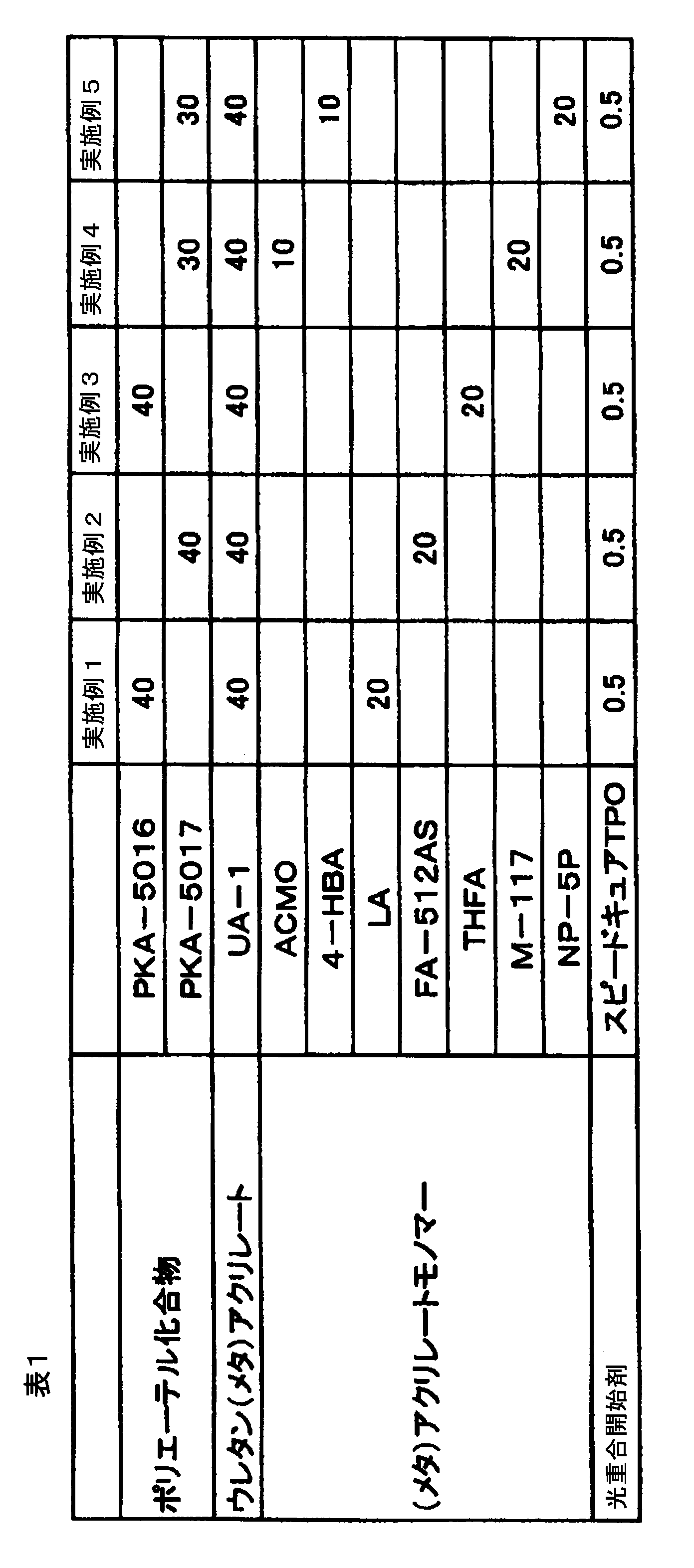
ユニセーフPKA-5016:ポリエチレングリコール-ポリプロピレングリコールアリルブチルエーテル(一般式(1)において、R1がアリル、R2がブチル、n=15、m=15、数平均分子量1600である化合物)、日油(株)社製
ユニセーフPKA-5017:ポリエチレングリコール-ポリプロピレングリコールアリルブチルエーテル(一般式(1)において、R1がアリル、R2がブチル、n=23、m=23、数平均分子量2500である化合物)、日油(株)社製
UA-1:ポリプロピレングリコール(分子量3000)、イソホロンジイソシアネート、2-ヒドロキシエチルアクリレートの3成分をモル比1:1.3:2の反応物。
ACMO:アクリロイルモルホリン、興人(株)社製
4-HBA:4-ヒドロキシブチルアクリレート、大阪有機化学工業(株)社製
LA:ラウリルアクリレート、大阪有機化学工業(株)社製
FA-512AS:ジシクロペンテニルオキシエチルアクリレート、日立化成工業(株)社製
THFA:テトラヒドロフルフリルアクリレート、大阪有機化学工業(株)社製
M-117:プロピレンオキサイド2.5モル変性ノニルフェニルアクリレート、東亜合成(株)社製
NP-5P:プロピレンオキサイド5モル変性ノニルフェニルアクリレート、第一工業製薬(株)社製
スピードキュアTPO:2,4,6-トリメチルベンゾイルジフェニルフォスフィンオキサイド、LAMBSON社製
本発明の樹脂硬化物層を有する光学部材の作製
3.5インチの液晶表示ユニットに調製した実施例1~5の各紫外線硬化型樹脂組成物を、膜厚が250μmとなるように塗布した。ついで、タッチセンサーを有するガラス基板を各紫外線硬化型樹脂組成物上に乗せ、液晶表示ユニットと貼り合せた。最後に、タッチセンサーを有するガラス基板側から超高圧水銀ランプ(TOSCURE752、ハリソン東芝ライティング社製)で、200mJ/cm2の紫外線照射を行い、樹脂硬化物層を硬化させ、本発明の光学部材を作製した。
図2(a)、図4(a)に示すように、金属製のワイヤー4を用いて樹脂硬化物層3を切断し、液晶表示ユニット1とタッチセンサーを有するガラス基板2を分離した。
図2(b)に示すように、金属製ロール(材質:ステンレス、形状:円筒形状、寸法:底面の直径5cm、軸方向長さ10cm)5を液晶表示ユニット1上にある樹脂硬化物層3およびタッチセンサーを有するガラス基板2上にある樹脂硬化物層3に接触させた。次いで、図2(c)に示すように、金属製ロール5に圧力6をかけて、金属製ロール5と樹脂硬化物層3表面を付着させた。最後に、図2(d)に示すように金属製ロール5を回転させ、樹脂硬化物層3を剥離した。
図4(b)に示すように、樹脂製フィルム(材質:PET)7を液晶表示ユニット1上にある樹脂硬化物層3およびタッチセンサーを有するガラス基板2上にある樹脂硬化物層3に接触した。次いで、図4(c)に示すように、樹脂製フィルム7に圧力6をかけて、樹脂製フィルム7と樹脂硬化物層3表面を付着させた。最後に、図4(d)に示すように端から樹脂製フィルム7を上方に引き上げ、樹脂硬化物層3を剥離した。
3.5インチの液晶表示ユニット1に調製した実施例1~5の各紫外線硬化型樹脂組成物を、膜厚が250μmとなるように塗布した。ついで、タッチセンサーを有するガラス基板2を各紫外線硬化型樹脂組成物上に乗せ、液晶表示ユニット1と貼り合せた。最後に、タッチセンサーを有するガラス基板2側から超高圧水銀ランプ(TOSCURE752、ハリソン東芝ライティング社製)で、表2に記載の通りに20~1500mJ/cm2の範囲で紫外線照射を行い、樹脂硬化物層3を硬化させ、本発明の光学部材を作製した。
そして、図4(a)に示すように、金属製のワイヤー4を用いて樹脂硬化物層3を切断し、液晶表示ユニット1とタッチセンサーを有するガラス基板2を分離後、図4(b)に示すように、樹脂製フィルム(材質:PET)7を液晶表示ユニット1上にある樹脂硬化物層3およびタッチセンサーを有するガラス基板2上にある樹脂硬化物層3に接触させた。次いで、図4(c)に示すように、樹脂製フィルム7に圧力6をかけて、樹脂製フィルム7と樹脂硬化物層3表面を付着させた。最後に、図4(d)に示すように端から樹脂製フィルム7を上方に引き上げ、樹脂硬化物層3を剥離して、樹脂性フィルム7及びガラス基板2に付着している樹脂硬化物の状態を観察した。
剥離性は下記の基準で評価したところ、結果は表2に記載の通りとなった。
(剥離性能)
○:ガラス基板に樹脂硬化物の付着が目視で確認されず、樹脂製フィルムに樹脂硬化物層の断片や切れ目が存在しなかった。
△:ガラス基板に樹脂硬化物の付着が目視で確認されなかったが、樹脂製フィルムに樹脂硬化物層の断片や切れ目が存在した。
×:ガラス基板に樹脂硬化物の付着が目視で確認された。

硬化収縮率(%)=(DS-DL)÷DS×100
図5(a)に示すように、硬化部分と未硬化部分を有するように半硬化されてなる樹脂硬化物層3を、張り合わされている光学基材に対して硬化物層3が形成されている方向と逆方向へ力を加えて引き剥がして分断した。
その後、図5(b)に示すように、樹脂製フィルム(材質:ポリ塩化ビニリデン)7を液晶表示ユニット上にある樹脂硬化物層3およびタッチセンサーを有するガラス基板2上にある樹脂硬化物層3に接触した。次いで、図5(c)に示すように、紫外線8を照射することで未硬化部分を硬化させて、樹脂製フィルム7と樹脂硬化物層3表面を付着させた。最後に、図5(d)に示すように端から樹脂製フィルム7を上方に引き上げ、樹脂硬化物層3を剥離した。
3.5インチの液晶表示ユニットに調製した実施例1~5の各紫外線硬化型樹脂組成物を、膜厚が250μmとなるように塗布した。ついで、タッチセンサーを有するガラス基板を各紫外線硬化型樹脂組成物上に乗せ、液晶表示ユニット1と貼り合せた。最後に、タッチセンサーを有するガラス基板2側から超高圧水銀ランプ(Aicure SPOT TYPE ANUO5204、パナソニック社製)で、四つの頂点に30mJ/cm2の照度で紫外線照射を行い、硬化部分と未硬化部分を有するように半硬化されてなる樹脂硬化物層3を有する本発明の光学部材を作製した。
そして、図5(a)に示すように、硬化部分と未硬化部分を有するように半硬化されてなる樹脂硬化物層3を、張り合わされている光学基材に対して硬化物層3が形成されている方向と逆方向へ力を加えて引き剥がして分断後、図5(b)に示すように、樹脂製フィルム(材質:ポリ塩化ビニリデン)7を液晶表示ユニット1上にある樹脂硬化物層3およびタッチセンサーを有するガラス基板2上にある樹脂硬化物層3に接触させた。次いで、図5(c)に示すように、樹脂製フィルム7側から超高圧水銀ランプ(TOSCURE752、ハリソン東芝ライティング社製)で、表3記載の通りに20~1500mJ/cm2の範囲で紫外線8を照射して未硬化部分を硬化させることにより、樹脂製フィルム7と樹脂硬化物層3表面を付着させた。最後に、図5(d)に示すように端から樹脂製フィルム7を上方に引き上げ、樹脂硬化物層3を剥離して、樹脂性フィルム7及びガラス基板2に付着している樹脂硬化物の状態を観察した。
剥離性は下記の基準で評価したところ、結果は表3に記載の通りとなった。
(剥離性能)
○:ガラス基板に樹脂硬化物の付着が目視で確認されず、樹脂製フィルムに樹脂硬化物層の断片や切れ目が存在しなかった。
△:ガラス基板に樹脂硬化物の付着が目視で確認されなかったが、樹脂製フィルムに樹脂硬化物層の断片や切れ目が存在した。
×:ガラス基板に樹脂硬化物の付着が目視で確認された。

なお、本出願は、2011年11月21日付で出願された日本特許出願(特願2011-253891)に基づいており、その全体が引用により援用される。また、ここに引用されるすべての参照は全体として取り込まれる。
Claims (12)
- 光学基材表面に存在する紫外線硬化型樹脂組成物を硬化してなる層を剥離する下記(工程1)~(工程3)を含む方法に使用される前記紫外線硬化型樹脂組成物であって、(メタ)アクリレート(A)及び光重合開始剤(B)を含有する紫外線硬化型樹脂組成物。
(工程1)剥離用基材を、紫外線硬化型樹脂組成物を硬化してなる層に接触させる工程。
(工程2)紫外線硬化型樹脂組成物を硬化してなる層を剥離用基材に付着させる工程。
(工程3)剥離用基材に紫外線硬化型樹脂組成物を硬化してなる層を剥離基材の表面に付着させて捕集することにより光学基材から剥離させることで、光学基材と紫外線硬化型樹脂組成物を硬化してなる層を剥離していく工程。 - 前記(メタ)アクリレート(A)が、ウレタン(メタ)アクリレート、ポリイソプレン骨格を有する(メタ)アクリレート、(メタ)アクリレートモノマーからなる群から選ばれる1種以上の(メタ)アクリレートであることを特徴とする請求項1に記載の紫外線硬化型樹脂組成物。
- 前記(メタ)アクリレート(A)がウレタン(メタ)アクリレートであって、ウレタン(メタ)アクリレートが、ポリオール、ポリイソシアネート及びヒドロキシル基含有(メタ)アクリレートを反応させることによって得られるウレタン(メタ)アクリレートであって、ポリオールが、ポリエチレングリコール、ポリプロピレングリコール、ポリテトラメチレングリコール、エチレンオキサイド変性ビスフェノールA、プロピレンオキサイド変性ビスフェノールA、ポリエステルポリオールからなる群から選ばれる1種以上であることを特徴とする請求項2に記載の紫外線硬化型樹脂組成物。
- 前記(メタ)アクリレート(A)がウレタン(メタ)アクリレートであって、ウレタン(メタ)アクリレートが、ポリプロピレングリコール、ポリイソシアネート及びヒドロキシル基含有(メタ)アクリレートを反応させることによって得られるウレタン(メタ)アクリレートである請求項3に記載の紫外線硬化型樹脂組成物。
- 前記(メタ)アクリレートが(メタ)アクリレートモノマーであって、(メタ)アクリレートモノマーがラウリル(メタ)アクリレート、2-エチルヘキシルカルビトールアクリレート、アクリロイルモルホリン、4-ヒドロキシブチル(メタ)アクリレート、テトラヒドロフルフリル(メタ)アクリレート、イソステアリル(メタ)アクリレート、ポリプロピレンオキサイド変性ノニルフェニル(メタ)アクリレート、ジシクロペンテニルオキシエチル(メタ)アクリレートからなる群から選ばれる1種以上であることを特徴とする請求項2に記載の紫外線硬化型樹脂組成物。
- (工程1)~(工程3)を有する方法による光学基材表面に存在する紫外線硬化型樹脂組成物を硬化してなる層を剥離する剥離方法。
(工程1)剥離用基材を、紫外線硬化型樹脂組成物を硬化してなる層に接触させる工程。
(工程2)紫外線硬化型樹脂組成物を硬化してなる層を剥離用基材に付着させる工程。
(工程3)剥離用基材に紫外線硬化型樹脂組成物を硬化してなる層を剥離基材の表面に付着させて捕集することにより光学基材から剥離させることで、光学基材と紫外線硬化型樹脂組成物を硬化してなる層を剥離していく工程。 - 前記(工程2)の付着させる工程が、圧力をかける工程である請求項6記載の剥離方法。
- 前記紫外線硬化型樹脂組成物が、(メタ)アクリレート(A)及び光重合開始剤(B)を含有する紫外線硬化型樹脂組成物であり、(メタ)アクリレート(A)が、ポリオール、ポリイソシアネート及びヒドロキシル基含有(メタ)アクリレートを反応させることによって得られるウレタン(メタ)アクリレートであって、前記ポリオールが、ポリエチレングリコール、ポリプロピレングリコール、ポリテトラメチレングリコール、エチレンオキサイド変性ビスフェノールA、プロピレンオキサイド変性ビスフェノールA、ポリエステルポリオールからなる群から選ばれる1種以上であることを特徴とする請求項6または請求項7に記載の剥離方法。
- 前記紫外線硬化型樹脂組成物が、(メタ)アクリレート(A)及び光重合開始剤(B)を含有する紫外線硬化型樹脂組成物であり、(メタ)アクリレート(A)が、ラウリル(メタ)アクリレート、2-エチルヘキシルカルビトールアクリレート、アクリロイルモルホリン、4-ヒドロキシブチル(メタ)アクリレート、テトラヒドロフルフリル(メタ)アクリレート、イソステアリル(メタ)アクリレート、ポリプロピレンオキサイド変性ノニルフェニル(メタ)アクリレート、ジシクロペンテニルオキシエチル(メタ)アクリレートからなる群から選ばれる1種以上であることを特徴とする請求項6または7に記載の剥離方法。
- 前記光学基材が、透明ガラス基板、透明樹脂基板、タッチセンサー付きガラス基板、液晶表示ユニット、プラズマ表示ユニット、有機EL表示ユニットからなる群から選ばれる1種以上であることを特徴とする請求項6~9のいずれか一項に記載の剥離方法。
- 前記剥離用基材が、金属製ロール、樹脂製ロール、金属製基板、樹脂製基板、樹脂製フィルムからなる群から選ばれる1種以上であることを特徴とする請求項6~10のいずれか一項に記載の剥離方法。
- 前記(工程1)の前に、光学基材表面に存在する紫外線硬化型樹脂組成物を硬化してなる層を、10~1000mJ/cm2の照射量で紫外線を照射することで得ることを特徴とする請求項6~11のいずれか一項に記載の剥離方法。
Priority Applications (3)
| Application Number | Priority Date | Filing Date | Title |
|---|---|---|---|
| CN201280057253.1A CN104024295B (zh) | 2011-11-21 | 2012-09-26 | 紫外线固化型树脂组合物及其固化物的剥离方法 |
| KR1020147013657A KR20140099457A (ko) | 2011-11-21 | 2012-09-26 | 자외선 경화형 수지 조성물, 및 그 경화물의 박리방법 |
| JP2013545831A JP5970473B2 (ja) | 2011-11-21 | 2012-09-26 | 紫外線硬化型樹脂組成物、及びその硬化物の剥離方法 |
Applications Claiming Priority (2)
| Application Number | Priority Date | Filing Date | Title |
|---|---|---|---|
| JP2011253891 | 2011-11-21 | ||
| JP2011-253891 | 2011-11-21 |
Publications (1)
| Publication Number | Publication Date |
|---|---|
| WO2013077080A1 true WO2013077080A1 (ja) | 2013-05-30 |
Family
ID=48469536
Family Applications (1)
| Application Number | Title | Priority Date | Filing Date |
|---|---|---|---|
| PCT/JP2012/074802 Ceased WO2013077080A1 (ja) | 2011-11-21 | 2012-09-26 | 紫外線硬化型樹脂組成物、及びその硬化物の剥離方法 |
Country Status (5)
| Country | Link |
|---|---|
| JP (1) | JP5970473B2 (ja) |
| KR (1) | KR20140099457A (ja) |
| CN (1) | CN104024295B (ja) |
| TW (1) | TWI535745B (ja) |
| WO (1) | WO2013077080A1 (ja) |
Cited By (3)
| Publication number | Priority date | Publication date | Assignee | Title |
|---|---|---|---|---|
| CN106536653A (zh) * | 2014-07-22 | 2017-03-22 | 日本合成化学工业株式会社 | 活性能量射线固化性粘合剂组合物、使用其而得到的粘合剂和粘合片 |
| EP3303057A1 (en) * | 2015-06-04 | 2018-04-11 | 3M Innovative Properties Company | Methods of bonding hardware to vehicular glass |
| JP2021035779A (ja) * | 2020-12-04 | 2021-03-04 | デクセリアルズ株式会社 | 積層体の製造方法、及び光硬化性樹脂組成物 |
Families Citing this family (4)
| Publication number | Priority date | Publication date | Assignee | Title |
|---|---|---|---|---|
| KR101891729B1 (ko) * | 2015-01-20 | 2018-08-24 | 주식회사 엘지화학 | 경화성 조성물 |
| US10391750B2 (en) | 2015-09-03 | 2019-08-27 | Dongwoo Fine-Chem Co., Ltd. | Cover window plate and image display device including the same |
| CN106977657A (zh) * | 2016-01-19 | 2017-07-25 | 杭州吉华高分子材料股份有限公司 | 一种水性可剥离树脂及其制备方法和应用 |
| WO2018021350A1 (ja) * | 2016-07-26 | 2018-02-01 | 日産化学工業株式会社 | 易剥離性保護膜形成用組成物 |
Citations (12)
| Publication number | Priority date | Publication date | Assignee | Title |
|---|---|---|---|---|
| JP2000038546A (ja) * | 1998-07-24 | 2000-02-08 | Mitsubishi Rayon Co Ltd | 光硬化型接着剤組成物およびそれを用いた光学部材 |
| JP2004077887A (ja) * | 2002-06-18 | 2004-03-11 | Sony Corp | 表示装置および表示装置を有する電子機器 |
| JP2008101105A (ja) * | 2006-10-19 | 2008-05-01 | Denki Kagaku Kogyo Kk | 硬化性組成物 |
| WO2008111580A1 (ja) * | 2007-03-12 | 2008-09-18 | Toagosei Co., Ltd. | 光学フィルム積層体及びそれを用いた表示装置 |
| JP2009001655A (ja) * | 2007-06-21 | 2009-01-08 | Nippon Kayaku Co Ltd | 光硬化型透明接着剤組成物 |
| WO2010027041A1 (ja) * | 2008-09-05 | 2010-03-11 | 協立化学産業株式会社 | 光学機能材料を貼り合わせるための光硬化型樹脂組成物 |
| JP2010122563A (ja) * | 2008-11-21 | 2010-06-03 | Hitachi Displays Ltd | 表示装置及びその製造方法 |
| JP2011048055A (ja) * | 2009-08-26 | 2011-03-10 | Hitachi Displays Ltd | 液晶表示装置 |
| JP2011511851A (ja) * | 2007-12-28 | 2011-04-14 | イー・アイ・デュポン・ドウ・ヌムール・アンド・カンパニー | 化学線硬化型接着剤組成物 |
| JP2011158851A (ja) * | 2010-02-04 | 2011-08-18 | Hitachi Displays Ltd | 表示装置およびその製造方法 |
| JP2012136557A (ja) * | 2010-12-24 | 2012-07-19 | Dic Corp | 紫外線硬化型粘着剤用樹脂組成物、粘着剤及び積層体 |
| JP2012172034A (ja) * | 2011-02-21 | 2012-09-10 | Jnc Corp | 接着した部材からの光硬化性接着剤の除去方法、及び二部材の接着方法 |
Family Cites Families (2)
| Publication number | Priority date | Publication date | Assignee | Title |
|---|---|---|---|---|
| JP4651799B2 (ja) * | 2000-10-18 | 2011-03-16 | 日東電工株式会社 | エネルギー線硬化型熱剥離性粘着シート、及びこれを用いた切断片の製造方法 |
| WO2010053078A1 (ja) * | 2008-11-05 | 2010-05-14 | 日本化薬株式会社 | 光ディスク用紫外線硬化型樹脂組成物およびその硬化物 |
-
2012
- 2012-09-26 KR KR1020147013657A patent/KR20140099457A/ko not_active Withdrawn
- 2012-09-26 WO PCT/JP2012/074802 patent/WO2013077080A1/ja not_active Ceased
- 2012-09-26 JP JP2013545831A patent/JP5970473B2/ja not_active Expired - Fee Related
- 2012-09-26 CN CN201280057253.1A patent/CN104024295B/zh not_active Expired - Fee Related
- 2012-09-28 TW TW101135806A patent/TWI535745B/zh not_active IP Right Cessation
Patent Citations (12)
| Publication number | Priority date | Publication date | Assignee | Title |
|---|---|---|---|---|
| JP2000038546A (ja) * | 1998-07-24 | 2000-02-08 | Mitsubishi Rayon Co Ltd | 光硬化型接着剤組成物およびそれを用いた光学部材 |
| JP2004077887A (ja) * | 2002-06-18 | 2004-03-11 | Sony Corp | 表示装置および表示装置を有する電子機器 |
| JP2008101105A (ja) * | 2006-10-19 | 2008-05-01 | Denki Kagaku Kogyo Kk | 硬化性組成物 |
| WO2008111580A1 (ja) * | 2007-03-12 | 2008-09-18 | Toagosei Co., Ltd. | 光学フィルム積層体及びそれを用いた表示装置 |
| JP2009001655A (ja) * | 2007-06-21 | 2009-01-08 | Nippon Kayaku Co Ltd | 光硬化型透明接着剤組成物 |
| JP2011511851A (ja) * | 2007-12-28 | 2011-04-14 | イー・アイ・デュポン・ドウ・ヌムール・アンド・カンパニー | 化学線硬化型接着剤組成物 |
| WO2010027041A1 (ja) * | 2008-09-05 | 2010-03-11 | 協立化学産業株式会社 | 光学機能材料を貼り合わせるための光硬化型樹脂組成物 |
| JP2010122563A (ja) * | 2008-11-21 | 2010-06-03 | Hitachi Displays Ltd | 表示装置及びその製造方法 |
| JP2011048055A (ja) * | 2009-08-26 | 2011-03-10 | Hitachi Displays Ltd | 液晶表示装置 |
| JP2011158851A (ja) * | 2010-02-04 | 2011-08-18 | Hitachi Displays Ltd | 表示装置およびその製造方法 |
| JP2012136557A (ja) * | 2010-12-24 | 2012-07-19 | Dic Corp | 紫外線硬化型粘着剤用樹脂組成物、粘着剤及び積層体 |
| JP2012172034A (ja) * | 2011-02-21 | 2012-09-10 | Jnc Corp | 接着した部材からの光硬化性接着剤の除去方法、及び二部材の接着方法 |
Cited By (7)
| Publication number | Priority date | Publication date | Assignee | Title |
|---|---|---|---|---|
| CN106536653A (zh) * | 2014-07-22 | 2017-03-22 | 日本合成化学工业株式会社 | 活性能量射线固化性粘合剂组合物、使用其而得到的粘合剂和粘合片 |
| EP3303057A1 (en) * | 2015-06-04 | 2018-04-11 | 3M Innovative Properties Company | Methods of bonding hardware to vehicular glass |
| US10927276B2 (en) | 2015-06-04 | 2021-02-23 | 3M Innovative Properties Company | Methods of bonding hardware to vehicular glass |
| US11352524B2 (en) | 2015-06-04 | 2022-06-07 | 3M Innovative Properties Company | Methods of bonding substrates together |
| US11773295B2 (en) | 2015-06-04 | 2023-10-03 | 3M Innovative Properties Company | Methods of bonding substrates together |
| JP2021035779A (ja) * | 2020-12-04 | 2021-03-04 | デクセリアルズ株式会社 | 積層体の製造方法、及び光硬化性樹脂組成物 |
| JP7170703B2 (ja) | 2020-12-04 | 2022-11-14 | デクセリアルズ株式会社 | 積層体の製造方法、及び光硬化性樹脂組成物 |
Also Published As
| Publication number | Publication date |
|---|---|
| CN104024295B (zh) | 2016-10-19 |
| TW201329122A (zh) | 2013-07-16 |
| TWI535745B (zh) | 2016-06-01 |
| CN104024295A (zh) | 2014-09-03 |
| JP5970473B2 (ja) | 2016-08-17 |
| KR20140099457A (ko) | 2014-08-12 |
| JPWO2013077080A1 (ja) | 2015-04-27 |
Similar Documents
| Publication | Publication Date | Title |
|---|---|---|
| JP6568567B2 (ja) | 紫外線硬化型樹脂組成物 | |
| EP2769843A1 (en) | Method for producing optical member and use of uv-curable resin composition therefor | |
| JP5970473B2 (ja) | 紫外線硬化型樹脂組成物、及びその硬化物の剥離方法 | |
| JP6620092B2 (ja) | タッチパネル用紫外線硬化型樹脂組成物、それを用いた貼り合せ方法及び物品 | |
| WO2015190552A1 (ja) | タッチパネル用紫外線硬化型樹脂組成物、それを用いた貼り合せ方法及び物品 | |
| WO2015190561A1 (ja) | タッチパネル用紫外線硬化型樹脂組成物、それを用いた貼り合せ方法及び物品 | |
| JP6378184B2 (ja) | 光学部材の製造方法及びそれに用いる紫外線硬化型樹脂組成物 | |
| WO2015190571A1 (ja) | タッチパネル用紫外線硬化型樹脂組成物、それを用いた貼り合せ方法及び物品 | |
| KR102564149B1 (ko) | 공정용 보호필름 |
Legal Events
| Date | Code | Title | Description |
|---|---|---|---|
| 121 | Ep: the epo has been informed by wipo that ep was designated in this application |
Ref document number: 12851717 Country of ref document: EP Kind code of ref document: A1 |
|
| ENP | Entry into the national phase |
Ref document number: 2013545831 Country of ref document: JP Kind code of ref document: A |
|
| ENP | Entry into the national phase |
Ref document number: 20147013657 Country of ref document: KR Kind code of ref document: A |
|
| NENP | Non-entry into the national phase |
Ref country code: DE |
|
| 122 | Ep: pct application non-entry in european phase |
Ref document number: 12851717 Country of ref document: EP Kind code of ref document: A1 |