WO2013069679A1 - 画像形成装置、画像形成装置の制御方法、及びプログラム - Google Patents
画像形成装置、画像形成装置の制御方法、及びプログラム Download PDFInfo
- Publication number
- WO2013069679A1 WO2013069679A1 PCT/JP2012/078833 JP2012078833W WO2013069679A1 WO 2013069679 A1 WO2013069679 A1 WO 2013069679A1 JP 2012078833 W JP2012078833 W JP 2012078833W WO 2013069679 A1 WO2013069679 A1 WO 2013069679A1
- Authority
- WO
- WIPO (PCT)
- Prior art keywords
- image forming
- mode
- forming apparatus
- activation
- controller
- Prior art date
- Legal status (The legal status is an assumption and is not a legal conclusion. Google has not performed a legal analysis and makes no representation as to the accuracy of the status listed.)
- Ceased
Links
Images
Classifications
-
- H—ELECTRICITY
- H04—ELECTRIC COMMUNICATION TECHNIQUE
- H04N—PICTORIAL COMMUNICATION, e.g. TELEVISION
- H04N1/00—Scanning, transmission or reproduction of documents or the like, e.g. facsimile transmission; Details thereof
- H04N1/00885—Power supply means, e.g. arrangements for the control of power supply to the apparatus or components thereof
- H04N1/00904—Arrangements for supplying power to different circuits or for supplying power at different levels
-
- G—PHYSICS
- G03—PHOTOGRAPHY; CINEMATOGRAPHY; ANALOGOUS TECHNIQUES USING WAVES OTHER THAN OPTICAL WAVES; ELECTROGRAPHY; HOLOGRAPHY
- G03G—ELECTROGRAPHY; ELECTROPHOTOGRAPHY; MAGNETOGRAPHY
- G03G21/00—Arrangements not provided for by groups G03G13/00 - G03G19/00, e.g. cleaning, elimination of residual charge
-
- B—PERFORMING OPERATIONS; TRANSPORTING
- B41—PRINTING; LINING MACHINES; TYPEWRITERS; STAMPS
- B41J—TYPEWRITERS; SELECTIVE PRINTING MECHANISMS, i.e. MECHANISMS PRINTING OTHERWISE THAN FROM A FORME; CORRECTION OF TYPOGRAPHICAL ERRORS
- B41J29/00—Details of, or accessories for, typewriters or selective printing mechanisms not otherwise provided for
- B41J29/38—Drives, motors, controls or automatic cut-off devices for the entire printing mechanism
-
- G—PHYSICS
- G03—PHOTOGRAPHY; CINEMATOGRAPHY; ANALOGOUS TECHNIQUES USING WAVES OTHER THAN OPTICAL WAVES; ELECTROGRAPHY; HOLOGRAPHY
- G03G—ELECTROGRAPHY; ELECTROPHOTOGRAPHY; MAGNETOGRAPHY
- G03G15/00—Apparatus for electrographic processes using a charge pattern
- G03G15/50—Machine control of apparatus for electrographic processes using a charge pattern, e.g. regulating differents parts of the machine, multimode copiers, microprocessor control
- G03G15/5004—Power supply control, e.g. power-saving mode, automatic power turn-off
-
- G—PHYSICS
- G03—PHOTOGRAPHY; CINEMATOGRAPHY; ANALOGOUS TECHNIQUES USING WAVES OTHER THAN OPTICAL WAVES; ELECTROGRAPHY; HOLOGRAPHY
- G03G—ELECTROGRAPHY; ELECTROPHOTOGRAPHY; MAGNETOGRAPHY
- G03G21/00—Arrangements not provided for by groups G03G13/00 - G03G19/00, e.g. cleaning, elimination of residual charge
- G03G21/14—Electronic sequencing control
-
- H—ELECTRICITY
- H04—ELECTRIC COMMUNICATION TECHNIQUE
- H04N—PICTORIAL COMMUNICATION, e.g. TELEVISION
- H04N1/00—Scanning, transmission or reproduction of documents or the like, e.g. facsimile transmission; Details thereof
-
- H—ELECTRICITY
- H04—ELECTRIC COMMUNICATION TECHNIQUE
- H04N—PICTORIAL COMMUNICATION, e.g. TELEVISION
- H04N1/00—Scanning, transmission or reproduction of documents or the like, e.g. facsimile transmission; Details thereof
- H04N1/00912—Arrangements for controlling a still picture apparatus or components thereof not otherwise provided for
- H04N1/00928—Initialisation or control of normal start-up or shut-down, i.e. non failure or error related
-
- H—ELECTRICITY
- H04—ELECTRIC COMMUNICATION TECHNIQUE
- H04N—PICTORIAL COMMUNICATION, e.g. TELEVISION
- H04N1/00—Scanning, transmission or reproduction of documents or the like, e.g. facsimile transmission; Details thereof
- H04N1/00912—Arrangements for controlling a still picture apparatus or components thereof not otherwise provided for
- H04N1/00931—Synchronising different operations or sub-apparatus, e.g. controlling on-times taking into account different warm-up times
Definitions
- the present invention relates to activation of an image forming apparatus.
- the DRAM image is stored in a non-volatile storage area (for example, a hard disk), and the power switch A technology has been established that shortens the time required to start the software by loading the image into the DRAM and returning to the state before the power switch is turned off when turned on (hereinafter referred to as hibernation activation).
- a non-volatile storage area for example, a hard disk
- the image forming apparatus includes a job controller unit (hereinafter referred to as a controller) that generates and processes a normal job and a printer unit (hereinafter referred to as a printer device) that executes print processing.
- a controller job controller unit
- printer device printer unit
- the controller and printer device have separate CPUs and execute independent software.
- the device initialization is mainly performed, and it is difficult to apply the software startup shortening technology as it is. For this reason, at present, only the controller is activated at high speed, and the printer apparatus is in a waiting state for activation. As a result, the entire image forming apparatus takes time to complete activation.
- the present invention has been made to solve the above-described problems, and an object of the present invention is to provide a mechanism capable of speeding up the activation of the entire image forming apparatus.
- the present invention includes a control unit and an image forming unit, and includes a first startup mode and a second startup mode having a startup time shorter than the first startup mode as startup modes of the control unit.
- An image forming apparatus having a plurality of activation modes, wherein a setting unit that sets any one of the plurality of activation modes according to a user instruction, and the control when the image forming apparatus is activated
- a first control unit that activates the image forming unit in the activation mode set by the setting unit, and when the first activation mode is set by the setting unit when the image forming apparatus is activated,
- the image forming unit is activated by performing a predetermined initialization process, and when the second activation mode is set by the setting unit, the image forming unit is not performed without performing the predetermined initialization process.
- Start And having a second control means.
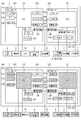
- FIG. 1 is a block diagram illustrating an example of a configuration of an image forming apparatus according to an embodiment of the present invention.
- 3 is a flowchart illustrating an example of operations of the controller 1 and the printer device 4 of the image forming apparatus illustrating Embodiment 1 of the present invention.
- FIG. 4 is a diagram illustrating an example of a start time in each start mode of the controller 1 and each initialization process time of the printer device 4.
- 6 is a flowchart illustrating an example of operations of the controller 1 and the printer device 4 of the image forming apparatus according to the second exemplary embodiment of the present invention.
- FIG. 1A is a block diagram showing an example of the configuration of an image forming apparatus showing an embodiment of the present invention.
- reference numeral 1 denotes a controller of the image forming apparatus, which includes a main board 100 and a sub board 120.
- FIG. 1A reference numeral 1 denotes a controller of the image forming apparatus, which includes a main board 100 and a sub board 120.
- the main board 100 is a so-called general-purpose CPU system.
- the CPU 101 controls the entire main board 100.
- the boot ROM 102 records the boot program so that it can be read by a computer.
- the memory 103 is a main memory used as a work memory by the CPU 101.
- the bus controller 104 has a bridge function with an external bus.
- the nonvolatile memory 105 is a storage device that can continuously hold data even when power supply is interrupted.
- the RTC 110 is a timepiece that operates with power supplied from a battery even when power supply to the main board 100 is interrupted.
- the disk controller 106 controls the storage device.
- the USB controller 108 controls the USB.
- the flash disk 107 is a relatively small-capacity storage device composed of semiconductor devices (for example, SSD; Solid State Drive).
- the USB memory 9, the operation unit 5, and the hard disk device 6 are connected to the main board 100.
- the hard disk device 6 does not necessarily need to be a hard disk as long as it is a non-volatile storage device.
- the sub board 120 includes a relatively small general-purpose CPU system and image processing hardware.
- the CPU 121 controls the entire sub board 120.
- the memory 123 is used as a work memory by the CPU 121.
- the bus controller 124 has a bridge function with an external bus.
- the non-volatile memory 125 is a storage device that can continuously retain data even when power supply is interrupted.
- the image processor 127 performs real-time digital image processing.
- the FAX apparatus (facsimile unit) 7 is directly controlled by the CPU 121.
- the power supply device 8 supplies power to the main board 100 and the sub board 120.
- the power control unit 109 manages the power supplied from the power supply device 8 so as to supply power to each necessary unit on the main board 100.
- the power control unit 128 manages the power supplied from the power supply device 8 to be supplied to each necessary unit on the sub board 120.
- the switch 10 is a power switch that receives a user power-off (power-off) / power-on (power-on) operation.
- the switch 10 When the switch 10 is operated, the CPU 101 is interrupted.
- the CPU 101 detects an interrupt, it controls the power control unit 109 according to the state. Further, the CPU 121 detects an operation of the switch 10 via the bus controllers 104 and 124 and controls the power control unit 128.
- This diagram is a block diagram and simplified.
- the CPU 101, the CPU 121, and the like include a large number of CPU peripheral hardware such as a chip set, a bus bridge, and a clock generator. It is not intended to limit the invention.
- the printer device 4 includes a CPU 41, a ROM 42, a RAM 43, and a non-volatile storage device 44 in the device, and various operations are realized by the CPU 41 executing programs stored in the ROM 42 using the RAM 43. Further, the printer device 4 stores a startup mode of the controller 1 described later in the nonvolatile storage device 44.
- controller 1 the operation of the controller 1 will be described by taking an image copy by a paper device as an example.
- the CPU 101 detects this instruction and sends an image reading command to the scanner device 2 via the CPU 121.
- the scanner device 2 Upon receiving the image reading command, the scanner device 2 optically scans a paper document to convert it into digital image data, and inputs the digital image data to the image processor 127 via the device controller 126.
- the image processor 127 DMA-transfers the digital image data to the memory 123 via the CPU 121 and temporarily stores the digital image data.
- the CPU 101 When the CPU 101 can confirm that a certain amount or all of the digital image data has entered the memory 123, it issues an image output instruction to the printer device 4 via the CPU 121, and the image data position ( Address). In response to the image output instruction, the image processor 127 transmits the image data stored in the notified position on the memory 123 to the printer device 4 via the device controller 126 in accordance with the synchronization signal from the printer device 4. To do.
- the printer device 4 Upon receiving the image data via the device controller 126, the printer device 4 prints the image data on a paper device.
- the CPU 101 when printing a plurality of copies, stores the image data on the memory 123 in the hard disk device 6.
- the image data stored in the hard disk device 6 is transmitted to the printer device 4 by the CPU 101 without inputting the image data from the scanner device 2, and the printer device. 4 is controlled to perform printing.
- the start mode of the controller (control unit) will be briefly described.
- the program In the normal activation mode (first activation mode), the program is activated in a volatile storage unit.
- the DRAM energization activation mode In the DRAM energization activation mode (second activation mode), activation is performed using a memory image held in a volatile storage unit.
- the hibernation start-up mode In the hibernation start-up mode (third start-up mode), the memory image held in the non-volatile storage means is read into the volatile storage means and started.
- FIG. 1B is a diagram illustrating an example of the power state of the image forming apparatus when the controller 1 is turned off in the DRAM energization start mode.
- the controller 1 when the controller 1 is turned off in the DRAM energization start mode, only the memory 103 and the switch 10 of the main board 100 of the controller 1 are energized. By holding the memory image before the power is turned off in the memory 103, the controller 1 can be activated at a high speed when the power is turned on. That is, in the DRAM energization start mode, the controller 1 continues to supply power to the memory 103 of the controller 1 while the switch 10 is turned off, and is stored in the memory 103 when the switch 10 is turned on. The state before the switch 10 is turned off is restored using the data.
- the controller 1 when the controller 1 is turned off in the hibernation start-up mode, the image forming apparatus is in a state where the power supply to all devices is cut off.
- the memory image before the power supply is turned off is stored in the hard disk device 6 or the flash disk 107, and the memory image before the power supply is turned off is developed in the memory 103 by using DMA transfer at the time of activation, thereby realizing the fast activation of the controller 1. . That is, in the hibernation activation mode, the controller 1 saves the data stored in the memory 103 when the switch 10 is turned off in the flash disk 107, and when the switch 10 is turned on, the flash disk 107 is stored. The data stored in the memory 10 is loaded into the memory 103 to return to the state before the switch 10 is turned off.
- the power consumption when the power is off is less by the amount of power supplied to the memory 103 and the switch 10 than in the DRAM energization startup mode.
- the boot time is longer than that when booting in the DRAM communication mode by the time for developing the memory image from the hard disk device 6 or the flash disk 107 to the memory 103.
- the CPU 101 sequentially reads images from the hard disk device 6 or the flash disk 107 to the memory 103, so that it takes time to start.
- the controller 1 always starts from the initial state every time, so that the operation stability is guaranteed.
- the DRAM energization start mode is used. Further, when the user does not want to consume power when the power is turned off but wants to start up at high speed, the hibernation start-up mode is used. When it takes a long time to start, the normal start mode is used.
- the operation unit 5 displays the characteristics of each of the above-described activation modes on the activation mode switching menu displayed on the display unit provided in the operation unit 5 and accepts the setting by user selection.
- the DRAM energization start mode and the hibernation start mode are collectively referred to as a fast start mode.
- the DRAM energization start mode is also referred to as a first fast start mode
- the hibernation start mode is also referred to as a second fast start mode.
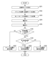
- FIG. 2 is a flowchart illustrating an example of operations of the controller 1 and the printer device 4 of the image forming apparatus according to the first exemplary embodiment of the present invention.
- the operation of the controller 1 is realized by the CPU 101 of the controller 1 reading and executing a program recorded in the boot ROM 102 so as to be readable by the computer.
- the operation of the printer apparatus 4 is realized by the CPU 41 of the printer apparatus 4 reading and executing a program recorded in the ROM 42 so as to be readable by a computer.
- the CPU 101 notifies the CPU 121 of the activation mode set in S201 via the bus controllers 104 and 124. Upon receiving this notification, the CPU 121 notifies the printer apparatus 4 of the activation mode notified from the CPU 101 via the device controller 126.
- the CPU 41 of the printer apparatus 4 Upon receiving the notification of the start mode from the CPU 121, the CPU 41 of the printer apparatus 4 stores the start mode notified from the CPU 121 in the nonvolatile storage device 44 (S203).
- the CPU 101 detects that the switch 10 has been turned off, performs necessary termination processing, and turns off the power of the image forming apparatus via the power control unit 109. (S204).
- each device including the controller 1 and the printer device 4 When the user operates the switch 10 to turn it on (S205), power is supplied to each device including the controller 1 and the printer device 4, and each device including the controller 1 and the printer device 4 executes various necessary startup processes. To start.
- step S206 the CPU 41 of the printer apparatus 4 reads the activation mode of the controller 1 stored in the nonvolatile storage device 44 in step S203, and determines whether or not the high-speed activation mode is set.
- the CPU 41 of the printer device 4 causes the printer device 4 to perform various initialization operations. Is activated at high speed (S208 to S210).
- the CPU 41 of the printer device 4 determines whether or not the startup mode of the controller 1 stored in the nonvolatile storage device 44 in S203 is the first high-speed startup mode.
- the CPU 41 of the printer apparatus 4 performs the first high-speed activation (S209).
- the activation mode of the controller 1 stored in the nonvolatile storage device 44 in S203 is not the first high-speed activation mode, that is, the second high-speed activation mode (hibernation activation mode) (No).
- the CPU 41 of the printer apparatus 4 performs the second high speed startup (S210).
- the activation mode notification from the controller 1 to the printer apparatus 4 shown in S202 can be executed during the processing of S204 or immediately after S205. Note that when the activation mode is notified immediately after S205, the storage in the nonvolatile area in S203 is not necessary. In this case, it is difficult to switch the activation process of the printer device 4 unless the activation mode is notified as soon as possible immediately after S205.
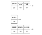
- FIG. 3 is a diagram showing an example of the activation time in each activation mode of the controller 1 and each initialization processing time of the printer apparatus 4.
- 301 is an example of the activation time in each activation mode of the controller 1.
- the activation time in the normal activation mode is 30 seconds.
- the activation time in the hibernation activation mode is 15 seconds, and the activation time in the DRAM energization activation mode is 5 seconds.
- These activation modes correspond to the activation modes notified from the controller 1 to the printer device 4 in S202 of FIG.
- the printer apparatus 4 performs various initialization operations in accordance with the notified start time of the start mode of the controller 1.
- the initialization operation of the printer apparatus 4 includes two operation systems of a toner stirring operation 302 and a toner density adjustment operation 303.
- the operation time (the time required from the start to the end of the operation) is 10 seconds.
- 303 is toner density adjustment.
- density adjustments 1 to 3 There are three types of adjustment methods for density adjustment (density adjustments 1 to 3), and each operation time is different.
- the operation time of density adjustment 1 is 10 seconds
- the operation time of density adjustment 2 is 15 seconds
- the operation time of density adjustment 3 is 5 seconds.
- the density adjustment operations (density adjustments 1 to 3) constituting the operation system 303 cannot be performed in parallel. Further, the stirring operation 302 and the concentration adjusting operation 303 can be operated in parallel.
- the printer apparatus 4 is activated to execute all initial activation operations (total 30 seconds) of the stirring operation, density adjustment 1, density adjustment 2, and density adjustment 3. Therefore, the entire image forming apparatus is activated in 30 seconds.
- the printer device 4 is started by executing a part of the first startup operation with omission. More specifically, the printer device 4 is activated with the density adjustment 1 and the density adjustment 3 omitted or with the density adjustment 2 omitted. Thereby, the printer apparatus 4 can be started up at high speed in 15 seconds (according to the starting time of the controller 1). Therefore, the entire image forming apparatus can be started up at high speed in 15 seconds.
- the printer device 4 is started by executing a part of the first startup operation with omission. Specifically, the printer device 4 omits the density adjustment 1 and the density adjustment 2 and starts to execute only the density adjustment 3. Thereby, the printer apparatus 4 can be started up at high speed in 5 seconds (according to the starting time of the controller 1). Therefore, the entire image forming apparatus can be started up at high speed in 5 seconds.
- the initialization operation of the printer apparatus 4 includes a plurality of operation systems that can be processed in parallel, and each of the operation systems is composed of one or a plurality of operations that cannot be processed in parallel. Then, when changing the initialization operation of the printer device 4, the CPU 41 of the printer device 4 performs an operation of the operation system constituting the operation system in accordance with the startup time of the controller 1 in each or all of the operation systems. Part or all are omitted. Thereby, the printer apparatus 4 can be started at high speed. Note that the configuration may be such that all of the initialization operation of the printer device 4 is omitted.
- a configuration in which part or all of the initialization operation of the printer device 4 is replaced with another operation having a shorter execution time may be employed.
- a configuration in which a part of the initialization operation of the printer device 4 is replaced with another operation having a shorter execution time and a part thereof is omitted (a configuration in which replacement and omission are combined) may be employed. That is, any configuration may be used as long as the initialization operation of the printer device 4 is changed in accordance with the startup time of the controller 1.
- the printer device 4 can change the initial operation according to the startup time of the controller 1 and perform high-speed startup. As a result, it is possible to solve the problem that only the controller is activated at high speed, waiting for activation of the printer apparatus, and it takes time to complete activation of the entire image forming apparatus, and the activation of the entire image forming apparatus can be accelerated. .
- the controller 41 of the printer device 4 when the CPU 41 of the printer device 4 is in the fast startup mode when the switch 1 is turned on, the controller 41 is matched with the startup time of the controller unit when it is started in the fast startup mode. Then, the initialization operation of the printer apparatus 4 is changed and the printer apparatus 4 is activated. For example, the CPU 41 of the printer apparatus 4 changes (omits or replaces) the initialization operation of the printer apparatus 4 so as not to exceed the activation time of the controller 1 when activated in the high-speed activation mode.
- the CPU 41 of the printer device 4 changes the initialization operation of the printer device 4 so that the startup time of the controller 1 when starting in the high speed startup mode does not exceed a predetermined time (for example, not to exceed 5 seconds). (Omission, replacement) may be performed.
- the CPU 41 of the printer apparatus 4 changes (omitted) the initialization operation of the printer apparatus 4 so as to minimize the difference between the startup time of the controller 1 and the startup time of the printer apparatus 4 when started in the high speed startup mode. , May be replaced).
- the activation time of the controller 1 in the hibernation activation mode is “13 seconds”.
- the printer device 4 is activated with the density adjustment 1 and the density adjustment 3 omitted or with the density adjustment 2 omitted.
- the printer device 4 can start up at a high speed in 15 seconds, at which the difference from the startup time of the controller 1 is minimized although the startup time of the controller 1 is exceeded.
- the printer device 4 when the fast startup mode is set in the controller 1, the printer device 4 always executes the fast startup with the initialization operation changed. If the initialization operation of the printer device 4 is changed (omitted or replaced), there is a possibility that the color may change depending on the toner state or the like when the power-off period is long.
- the printer device 4 when the power-off period is longer than a predetermined time, the printer device 4 is started by executing a normal initial startup operation without changing the initialization operation of the printer device 4. .
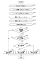
- FIG. 4 is a flowchart illustrating an example of operations of the controller 1 and the printer device 4 of the image forming apparatus according to the second exemplary embodiment of the present invention.
- the operation of the controller 1 is realized by the CPU 101 of the controller 1 reading and executing a program recorded in the boot ROM 102 so as to be readable by the computer.
- the operation of the printer apparatus 4 is realized by the CPU 41 of the printer apparatus 4 reading and executing a program recorded in the ROM 42 so as to be readable by a computer.
- the CPU 101 notifies the CPU 121 of the activation mode set in S401 via the bus controllers 104 and 124. Upon receiving this notification, the CPU 121 notifies the printer apparatus 4 of the activation mode notified from the CPU 101 via the device controller 126.
- the CPU 41 of the printer apparatus 4 stores the activation mode notified from the CPU 121 in the nonvolatile storage device 44 (S403).
- the CPU 101 detects that the switch 10 is turned off and starts the RTC 110 to measure the power-off period of the image forming apparatus. Thereafter, the CPU 101 performs necessary termination processing, and turns off the power source of the image forming apparatus via the power control unit 109 (S404).
- the CPU 101 calculates (acquires) a power-off period (power-off period) indicating a period during which the switch 10 is off (elapsed time from S405 to S405) based on the timer value of the RTC 110.
- the CPU 121 notifies the CPU 121 of the power-off period via the bus controllers 104 and 124. Upon receiving this notification, the CPU 121 notifies the printer apparatus 4 of the power-off period notified from the CPU 101 via the device controller 126.
- step S407 the CPU 41 of the printer apparatus 4 reads the activation mode of the controller 1 stored in the nonvolatile storage device 44 in step S203, and determines whether or not the high-speed activation mode is set.
- the CPU 41 of the printer apparatus 4 determines whether or not the power-off period notified in S406 exceeds a threshold value.
- this threshold is set to 8 hours.
- the threshold is determined by the characteristics of the printer device 4 and may be an arbitrary time. Moreover, the structure which exists in several steps may be sufficient as a threshold value.
- the CPU 41 of the printer apparatus 4 proceeds to S408 and normally starts the printer apparatus (S408). That is, when the power-off period exceeds the threshold, the CPU 41 of the printer apparatus 4 performs control so that the initialization operation of the printer apparatus 4 is not changed regardless of the startup mode of the controller 1.
- the CPU 41 of the printer apparatus 4 performs high-speed activation in which the printer apparatus 4 changes various initialization operations (S410 to S412).
- the CPU 41 of the printer apparatus 4 determines whether or not the activation mode of the controller 1 stored in the nonvolatile storage device 44 in S403 is the first high-speed activation mode.
- the CPU 41 of the printer device 4 performs the first high-speed activation (S411).
- the start mode notification from the controller 1 to the printer apparatus 4 shown in S402 may be executed during the process of S404, immediately after S405, or also in S406. Is possible. Note that when the activation mode is notified immediately after S405 or in S406, the storage in the nonvolatile area in S203 is not necessary. In this case, unless the activation mode is notified immediately after S205 or at the earliest possible timing of S406, it is difficult to switch the activation process of the printer apparatus 4.
- the initial operation is not changed when the power-off period is long and the initialization operation of the printer device 4 is required. Can be.
- the printer device 4 may be provided with a timer for measuring the power-off period so that the printer device 4 measures the power-off period.
- the printer device 4 is normally activated, so the controller 1 does not need to be activated at high speed.
- a threshold value determined by the printer device 4 is stored in advance in the nonvolatile memory 105 of the controller 1 and, when the power is turned on (S405), it is determined whether or not the Off period exceeds the threshold value. Then, when the Off period exceeds the threshold, the high-speed activation of the controller 1 is stopped. In this way, the activation of the controller 1 may be matched with the activation of the printer device 4. *
- the controller 1 may have a threshold value that matches the characteristics of self-confidence, calculate the power-off period in S405, stop the fast startup of the controller 1, and start up normally. In this case, the printer apparatus 4 is notified of the high-speed activation stop in S406, and the printer apparatus 4 is also activated normally.
- the printer device 4 when the period during which the power is turned off exceeds the threshold value, the printer device 4 does not change the initial operation and the normal initial operation even if the activation mode of the controller 1 is the high-speed activation mode. To start normally. As a result, the entire image forming apparatus can be started at a high speed with a short-time power supply OFF, while when the power supply is off for a long time, the initialization operation of the printer apparatus 4 is executed without being changed. It is possible to initialize the state and prevent deterioration of the quality of the formed image. That is, both high-speed startup and high-quality image formation can be realized.
- the present invention can take an embodiment as a system, apparatus, method, program, storage medium, or the like. Specifically, the present invention may be applied to a system composed of a plurality of devices, or may be applied to an apparatus composed of a single device.
Landscapes
- Engineering & Computer Science (AREA)
- Multimedia (AREA)
- Signal Processing (AREA)
- Physics & Mathematics (AREA)
- General Physics & Mathematics (AREA)
- Microelectronics & Electronic Packaging (AREA)
- Accessory Devices And Overall Control Thereof (AREA)
- Control Or Security For Electrophotography (AREA)
- Stored Programmes (AREA)
- Facsimiles In General (AREA)
Priority Applications (6)
| Application Number | Priority Date | Filing Date | Title |
|---|---|---|---|
| CN201280054751.0A CN103917924B (zh) | 2011-11-08 | 2012-11-07 | 图像形成装置及其控制方法 |
| RU2014123375/28A RU2573111C2 (ru) | 2011-11-08 | 2012-11-07 | Устройство формирования изображения, способ управления таким устройством и программа |
| BR112014010507-3A BR112014010507B1 (pt) | 2011-11-08 | 2012-11-07 | aparelho de formação de imagem e método para controlar o mesmo |
| EP12848482.1A EP2778798B1 (en) | 2011-11-08 | 2012-11-07 | Image forming apparatus, method for controlling image forming apparatus, and program |
| KR1020147015279A KR101636184B1 (ko) | 2011-11-08 | 2012-11-07 | 화상 형성 장치, 화상 형성 장치의 제어 방법 및 컴퓨터 판독가능 기록매체 |
| US13/888,074 US9621754B2 (en) | 2011-11-08 | 2013-05-06 | Image forming apparatus, method, and medium for affecting startup |
Applications Claiming Priority (2)
| Application Number | Priority Date | Filing Date | Title |
|---|---|---|---|
| JP2011-244671 | 2011-11-08 | ||
| JP2011244671A JP5984361B2 (ja) | 2011-11-08 | 2011-11-08 | 画像形成装置、画像形成装置の制御方法、及びプログラム |
Related Child Applications (1)
| Application Number | Title | Priority Date | Filing Date |
|---|---|---|---|
| US13/888,074 Continuation US9621754B2 (en) | 2011-11-08 | 2013-05-06 | Image forming apparatus, method, and medium for affecting startup |
Publications (1)
| Publication Number | Publication Date |
|---|---|
| WO2013069679A1 true WO2013069679A1 (ja) | 2013-05-16 |
Family
ID=48290053
Family Applications (1)
| Application Number | Title | Priority Date | Filing Date |
|---|---|---|---|
| PCT/JP2012/078833 Ceased WO2013069679A1 (ja) | 2011-11-08 | 2012-11-07 | 画像形成装置、画像形成装置の制御方法、及びプログラム |
Country Status (8)
| Country | Link |
|---|---|
| US (1) | US9621754B2 (enExample) |
| EP (1) | EP2778798B1 (enExample) |
| JP (1) | JP5984361B2 (enExample) |
| KR (1) | KR101636184B1 (enExample) |
| CN (1) | CN103917924B (enExample) |
| BR (1) | BR112014010507B1 (enExample) |
| RU (1) | RU2573111C2 (enExample) |
| WO (1) | WO2013069679A1 (enExample) |
Families Citing this family (10)
| Publication number | Priority date | Publication date | Assignee | Title |
|---|---|---|---|---|
| JP6048020B2 (ja) * | 2012-09-13 | 2016-12-21 | 株式会社リコー | 情報処理装置 |
| JP5889833B2 (ja) * | 2013-05-15 | 2016-03-22 | 京セラドキュメントソリューションズ株式会社 | 画像形成装置及びその起動制御方法 |
| JP5984790B2 (ja) * | 2013-12-18 | 2016-09-06 | キヤノン株式会社 | 情報処理装置、情報処理装置の制御方法、記憶媒体およびプログラム |
| JP6362326B2 (ja) * | 2013-12-26 | 2018-07-25 | キヤノン株式会社 | 印刷装置及び印刷装置の制御方法 |
| JP6049781B2 (ja) * | 2015-02-25 | 2016-12-21 | キヤノン株式会社 | 画像形成装置、制御方法、及びプログラム |
| JP6703309B2 (ja) * | 2017-03-23 | 2020-06-03 | 京セラドキュメントソリューションズ株式会社 | 電子機器およびデータ移行プログラム |
| JP2021149884A (ja) * | 2020-03-23 | 2021-09-27 | 株式会社リコー | 情報処理装置および情報処理装置の起動方法 |
| JP7669870B2 (ja) * | 2021-08-16 | 2025-04-30 | 富士フイルムビジネスイノベーション株式会社 | 情報処理装置およびプログラム |
| KR20230025985A (ko) | 2021-08-17 | 2023-02-24 | 휴렛-팩커드 디벨롭먼트 컴퍼니, 엘.피. | 토너 리필 카트리지를 장착부로부터 팝업시키는 구조 |
| US12360476B2 (en) | 2022-12-30 | 2025-07-15 | Zhuhai Pantum Electronics Co., Ltd. | Image-forming apparatus and control method thereof, and process cartridge chip for shortening first page output time |
Citations (9)
| Publication number | Priority date | Publication date | Assignee | Title |
|---|---|---|---|---|
| JPH0585020A (ja) | 1991-09-25 | 1993-04-06 | Tokyo Electric Co Ltd | プリンタ |
| JP2002091247A (ja) * | 2000-09-19 | 2002-03-27 | Minolta Co Ltd | 画像形成装置 |
| JP2002116586A (ja) * | 2000-10-05 | 2002-04-19 | Konica Corp | 画像形成装置 |
| JP2004347666A (ja) * | 2003-05-20 | 2004-12-09 | Konica Minolta Business Technologies Inc | 画像形成装置 |
| JP2005174156A (ja) * | 2003-12-15 | 2005-06-30 | Konica Minolta Business Technologies Inc | メモリ装置およびこれを備えた電子装置 |
| JP2005202105A (ja) * | 2004-01-15 | 2005-07-28 | Ricoh Co Ltd | 電子装置 |
| JP2008307733A (ja) * | 2007-06-13 | 2008-12-25 | Ricoh Co Ltd | 画像形成装置 |
| JP2009302940A (ja) * | 2008-06-13 | 2009-12-24 | Konica Minolta Business Technologies Inc | 画像形成装置 |
| JP2010117423A (ja) * | 2008-11-11 | 2010-05-27 | Kyocera Mita Corp | 画像形成装置 |
Family Cites Families (22)
| Publication number | Priority date | Publication date | Assignee | Title |
|---|---|---|---|---|
| JP3695020B2 (ja) * | 1996-11-21 | 2005-09-14 | セイコーエプソン株式会社 | インクジェット記録装置 |
| JP2002304088A (ja) * | 2001-04-09 | 2002-10-18 | Ricoh Co Ltd | 画像形成装置 |
| JP2003241590A (ja) * | 2001-12-12 | 2003-08-29 | Ricoh Co Ltd | 画像形成装置、及びプロセスカートリッジの初期設定動作方法、並びにプロセスカートリッジの初期設定動作プログラム |
| US7107487B2 (en) * | 2002-04-12 | 2006-09-12 | Lenovo (Singapore) Pte Ltd. | Fault tolerant sleep mode of operation |
| EP1621159A1 (en) | 2004-07-28 | 2006-02-01 | Cordis Corporation | Abdominal aortic aneurism (AAA) low profile support structure |
| JP4578178B2 (ja) * | 2004-08-23 | 2010-11-10 | 株式会社リコー | 画像形成装置 |
| JP2006095741A (ja) * | 2004-09-28 | 2006-04-13 | Fuji Xerox Co Ltd | 情報処理装置 |
| JP4498236B2 (ja) * | 2005-07-13 | 2010-07-07 | キヤノン株式会社 | 画像処理装置およびその制御方法 |
| JP4641469B2 (ja) * | 2005-09-06 | 2011-03-02 | キヤノン株式会社 | 画像形成装置、画像形成装置の制御方法、プログラム |
| JP4869779B2 (ja) * | 2006-05-09 | 2012-02-08 | 株式会社リコー | 起動制御装置、起動制御方法および画像形成装置 |
| JP2008204209A (ja) * | 2007-02-21 | 2008-09-04 | Sony Corp | 電子機器、復帰用インターフェース設定方法、復帰通信方法及びコンピュータプログラム |
| JP5178112B2 (ja) * | 2007-09-26 | 2013-04-10 | キヤノン株式会社 | 画像処理装置及び仮予約に係る制御方法 |
| JP5089432B2 (ja) * | 2008-02-26 | 2012-12-05 | 株式会社リコー | 画像読み取り装置及び画像形成装置 |
| JP5083772B2 (ja) * | 2008-06-27 | 2012-11-28 | 株式会社リコー | 画像形成装置、制御方法及び制御プログラム |
| JP5258453B2 (ja) * | 2008-08-22 | 2013-08-07 | キヤノン株式会社 | 画像形成装置及びその電力制御方法 |
| JP4888740B2 (ja) * | 2009-01-30 | 2012-02-29 | ブラザー工業株式会社 | 画像形成装置 |
| JP5555444B2 (ja) * | 2009-04-13 | 2014-07-23 | 京セラドキュメントソリューションズ株式会社 | 画像形成装置 |
| JP5460167B2 (ja) * | 2009-07-31 | 2014-04-02 | キヤノン株式会社 | 情報処理装置、情報処理装置の制御方法及び制御プログラム |
| JP5720086B2 (ja) * | 2009-08-10 | 2015-05-20 | セイコーエプソン株式会社 | 画像形成装置及び画像形成装置における制御方法 |
| JP5438429B2 (ja) * | 2009-08-11 | 2014-03-12 | キヤノン株式会社 | 画像形成装置及びその制御方法 |
| US8130249B2 (en) * | 2009-08-17 | 2012-03-06 | Xerox Corporation | Erase decoupled from writing for erasable paper |
| JP5146495B2 (ja) * | 2010-07-08 | 2013-02-20 | コニカミノルタビジネステクノロジーズ株式会社 | 画像処理装置およびハイバネーション起動方法 |
-
2011
- 2011-11-08 JP JP2011244671A patent/JP5984361B2/ja not_active Expired - Fee Related
-
2012
- 2012-11-07 BR BR112014010507-3A patent/BR112014010507B1/pt active IP Right Grant
- 2012-11-07 WO PCT/JP2012/078833 patent/WO2013069679A1/ja not_active Ceased
- 2012-11-07 RU RU2014123375/28A patent/RU2573111C2/ru not_active IP Right Cessation
- 2012-11-07 EP EP12848482.1A patent/EP2778798B1/en active Active
- 2012-11-07 KR KR1020147015279A patent/KR101636184B1/ko not_active Expired - Fee Related
- 2012-11-07 CN CN201280054751.0A patent/CN103917924B/zh active Active
-
2013
- 2013-05-06 US US13/888,074 patent/US9621754B2/en not_active Expired - Fee Related
Patent Citations (9)
| Publication number | Priority date | Publication date | Assignee | Title |
|---|---|---|---|---|
| JPH0585020A (ja) | 1991-09-25 | 1993-04-06 | Tokyo Electric Co Ltd | プリンタ |
| JP2002091247A (ja) * | 2000-09-19 | 2002-03-27 | Minolta Co Ltd | 画像形成装置 |
| JP2002116586A (ja) * | 2000-10-05 | 2002-04-19 | Konica Corp | 画像形成装置 |
| JP2004347666A (ja) * | 2003-05-20 | 2004-12-09 | Konica Minolta Business Technologies Inc | 画像形成装置 |
| JP2005174156A (ja) * | 2003-12-15 | 2005-06-30 | Konica Minolta Business Technologies Inc | メモリ装置およびこれを備えた電子装置 |
| JP2005202105A (ja) * | 2004-01-15 | 2005-07-28 | Ricoh Co Ltd | 電子装置 |
| JP2008307733A (ja) * | 2007-06-13 | 2008-12-25 | Ricoh Co Ltd | 画像形成装置 |
| JP2009302940A (ja) * | 2008-06-13 | 2009-12-24 | Konica Minolta Business Technologies Inc | 画像形成装置 |
| JP2010117423A (ja) * | 2008-11-11 | 2010-05-27 | Kyocera Mita Corp | 画像形成装置 |
Also Published As
| Publication number | Publication date |
|---|---|
| US9621754B2 (en) | 2017-04-11 |
| BR112014010507B1 (pt) | 2021-05-11 |
| EP2778798A4 (en) | 2015-08-19 |
| US20130250336A1 (en) | 2013-09-26 |
| BR112014010507A2 (pt) | 2017-05-02 |
| KR101636184B1 (ko) | 2016-07-04 |
| EP2778798A1 (en) | 2014-09-17 |
| RU2573111C2 (ru) | 2016-01-20 |
| RU2014123375A (ru) | 2015-12-20 |
| CN103917924B (zh) | 2020-04-10 |
| KR20140100502A (ko) | 2014-08-14 |
| JP2013101220A (ja) | 2013-05-23 |
| JP5984361B2 (ja) | 2016-09-06 |
| CN103917924A (zh) | 2014-07-09 |
| EP2778798B1 (en) | 2020-04-08 |
Similar Documents
| Publication | Publication Date | Title |
|---|---|---|
| JP5984361B2 (ja) | 画像形成装置、画像形成装置の制御方法、及びプログラム | |
| US11067932B2 (en) | Information processing apparatus capable of appropriately executing shutdown processing, method of controlling the information processing apparatus, and storage medium | |
| JP5460167B2 (ja) | 情報処理装置、情報処理装置の制御方法及び制御プログラム | |
| JP6041522B2 (ja) | 情報処理装置、情報処理装置の制御方法、プログラム及び記憶媒体 | |
| JP5780769B2 (ja) | データ処理装置、その制御方法およびプログラム、並びに記憶媒体 | |
| JP5885390B2 (ja) | 画像形成装置、画像形成装置の制御方法及びプログラム | |
| CN106341566B (zh) | 打印装置及打印装置的控制方法 | |
| EP2528314A1 (en) | Information processing apparatus and method of controlling launch thereof | |
| JP2012155534A (ja) | 電子機器及びその制御方法、並びにプログラム | |
| KR101596095B1 (ko) | 인쇄 장치 및 기록 매체 | |
| JP5701043B2 (ja) | 情報処理装置、情報処理装置の制御方法、及び、プログラム | |
| CN110418025B (zh) | 图像形成装置 | |
| JP2013041458A (ja) | データ処理装置及びその制御方法 | |
| US10033895B2 (en) | Printing apparatus having plurality of power states and control method therefor | |
| JP5967945B2 (ja) | 情報処理装置、情報処理装置の制御方法、及びプログラム | |
| JP2015123650A (ja) | 画像形成装置、画像形成装置の制御方法、及びプログラム | |
| US10582079B2 (en) | Image forming apparatus, method for controlling image forming apparatus, and recording medium | |
| CN112532798A (zh) | 信息处理装置以及记录媒体 | |
| JP5800861B2 (ja) | 情報処理装置、情報処理装置の制御方法及び制御プログラム | |
| US11627230B2 (en) | Information processing apparatus, information processing method, and non-transitory computer readable medium | |
| US9794440B2 (en) | Image forming apparatus that operates in normal mode and power saving mode, control method therefor, and storage medium | |
| JP2012091460A (ja) | 画像形成装置、その制御方法及びプログラム |
Legal Events
| Date | Code | Title | Description |
|---|---|---|---|
| 121 | Ep: the epo has been informed by wipo that ep was designated in this application |
Ref document number: 12848482 Country of ref document: EP Kind code of ref document: A1 |
|
| NENP | Non-entry into the national phase |
Ref country code: DE |
|
| WWE | Wipo information: entry into national phase |
Ref document number: 2012848482 Country of ref document: EP |
|
| ENP | Entry into the national phase |
Ref document number: 20147015279 Country of ref document: KR Kind code of ref document: A |
|
| ENP | Entry into the national phase |
Ref document number: 2014123375 Country of ref document: RU Kind code of ref document: A |
|
| REG | Reference to national code |
Ref country code: BR Ref legal event code: B01A Ref document number: 112014010507 Country of ref document: BR |
|
| ENP | Entry into the national phase |
Ref document number: 112014010507 Country of ref document: BR Kind code of ref document: A2 Effective date: 20140430 |