WO2013065183A1 - リアクトルおよびその製造方法 - Google Patents
リアクトルおよびその製造方法 Download PDFInfo
- Publication number
- WO2013065183A1 WO2013065183A1 PCT/JP2011/075472 JP2011075472W WO2013065183A1 WO 2013065183 A1 WO2013065183 A1 WO 2013065183A1 JP 2011075472 W JP2011075472 W JP 2011075472W WO 2013065183 A1 WO2013065183 A1 WO 2013065183A1
- Authority
- WO
- WIPO (PCT)
- Prior art keywords
- resin
- reactor
- coil
- bobbin
- slit
- Prior art date
Links
- 238000004519 manufacturing process Methods 0.000 title claims description 6
- 239000011347 resin Substances 0.000 claims abstract description 71
- 229920005989 resin Polymers 0.000 claims abstract description 71
- WABPQHHGFIMREM-UHFFFAOYSA-N lead(0) Chemical compound [Pb] WABPQHHGFIMREM-UHFFFAOYSA-N 0.000 claims abstract description 41
- 238000000465 moulding Methods 0.000 description 13
- 238000004804 winding Methods 0.000 description 8
- 239000000463 material Substances 0.000 description 6
- 238000000034 method Methods 0.000 description 6
- 239000012212 insulator Substances 0.000 description 4
- 238000005516 engineering process Methods 0.000 description 3
- 230000008569 process Effects 0.000 description 3
- 238000007789 sealing Methods 0.000 description 3
- 239000011265 semifinished product Substances 0.000 description 3
- 125000006850 spacer group Chemical group 0.000 description 3
- 238000009499 grossing Methods 0.000 description 2
- 238000001746 injection moulding Methods 0.000 description 2
- 229910000859 α-Fe Inorganic materials 0.000 description 2
- 239000000853 adhesive Substances 0.000 description 1
- 230000001070 adhesive effect Effects 0.000 description 1
- PNEYBMLMFCGWSK-UHFFFAOYSA-N aluminium oxide Inorganic materials [O-2].[O-2].[O-2].[Al+3].[Al+3] PNEYBMLMFCGWSK-UHFFFAOYSA-N 0.000 description 1
- 230000008901 benefit Effects 0.000 description 1
- 239000000919 ceramic Substances 0.000 description 1
- 230000001419 dependent effect Effects 0.000 description 1
- 230000006872 improvement Effects 0.000 description 1
- 238000009413 insulation Methods 0.000 description 1
- 238000012986 modification Methods 0.000 description 1
- 230000004048 modification Effects 0.000 description 1
- 230000002265 prevention Effects 0.000 description 1
- 238000010125 resin casting Methods 0.000 description 1
- 230000007480 spreading Effects 0.000 description 1
- 238000003892 spreading Methods 0.000 description 1
Images


Classifications
-
- H—ELECTRICITY
- H01—ELECTRIC ELEMENTS
- H01F—MAGNETS; INDUCTANCES; TRANSFORMERS; SELECTION OF MATERIALS FOR THEIR MAGNETIC PROPERTIES
- H01F41/00—Apparatus or processes specially adapted for manufacturing or assembling magnets, inductances or transformers; Apparatus or processes specially adapted for manufacturing materials characterised by their magnetic properties
- H01F41/02—Apparatus or processes specially adapted for manufacturing or assembling magnets, inductances or transformers; Apparatus or processes specially adapted for manufacturing materials characterised by their magnetic properties for manufacturing cores, coils, or magnets
- H01F41/04—Apparatus or processes specially adapted for manufacturing or assembling magnets, inductances or transformers; Apparatus or processes specially adapted for manufacturing materials characterised by their magnetic properties for manufacturing cores, coils, or magnets for manufacturing coils
- H01F41/10—Connecting leads to windings
-
- H—ELECTRICITY
- H01—ELECTRIC ELEMENTS
- H01F—MAGNETS; INDUCTANCES; TRANSFORMERS; SELECTION OF MATERIALS FOR THEIR MAGNETIC PROPERTIES
- H01F37/00—Fixed inductances not covered by group H01F17/00
-
- H—ELECTRICITY
- H01—ELECTRIC ELEMENTS
- H01F—MAGNETS; INDUCTANCES; TRANSFORMERS; SELECTION OF MATERIALS FOR THEIR MAGNETIC PROPERTIES
- H01F27/00—Details of transformers or inductances, in general
- H01F27/28—Coils; Windings; Conductive connections
- H01F27/32—Insulating of coils, windings, or parts thereof
- H01F27/324—Insulation between coil and core, between different winding sections, around the coil; Other insulation structures
- H01F27/325—Coil bobbins
-
- H—ELECTRICITY
- H01—ELECTRIC ELEMENTS
- H01F—MAGNETS; INDUCTANCES; TRANSFORMERS; SELECTION OF MATERIALS FOR THEIR MAGNETIC PROPERTIES
- H01F5/00—Coils
- H01F5/04—Arrangements of electric connections to coils, e.g. leads
-
- H—ELECTRICITY
- H01—ELECTRIC ELEMENTS
- H01F—MAGNETS; INDUCTANCES; TRANSFORMERS; SELECTION OF MATERIALS FOR THEIR MAGNETIC PROPERTIES
- H01F17/00—Fixed inductances of the signal type
- H01F17/04—Fixed inductances of the signal type with magnetic core
- H01F17/045—Fixed inductances of the signal type with magnetic core with core of cylindric geometry and coil wound along its longitudinal axis, i.e. rod or drum core
- H01F2017/046—Fixed inductances of the signal type with magnetic core with core of cylindric geometry and coil wound along its longitudinal axis, i.e. rod or drum core helical coil made of flat wire, e.g. with smaller extension of wire cross section in the direction of the longitudinal axis
-
- Y—GENERAL TAGGING OF NEW TECHNOLOGICAL DEVELOPMENTS; GENERAL TAGGING OF CROSS-SECTIONAL TECHNOLOGIES SPANNING OVER SEVERAL SECTIONS OF THE IPC; TECHNICAL SUBJECTS COVERED BY FORMER USPC CROSS-REFERENCE ART COLLECTIONS [XRACs] AND DIGESTS
- Y10—TECHNICAL SUBJECTS COVERED BY FORMER USPC
- Y10T—TECHNICAL SUBJECTS COVERED BY FORMER US CLASSIFICATION
- Y10T29/00—Metal working
- Y10T29/49—Method of mechanical manufacture
- Y10T29/49002—Electrical device making
- Y10T29/4902—Electromagnet, transformer or inductor
Definitions
- the present invention relates to a reactor (passive element using a coil) and a manufacturing method thereof.
- the reactor is also called “inductor”.
- a hybrid vehicle or an electric vehicle uses a motor as a drive source
- the electric circuit for the motor is often provided with a reactor.
- a reactor is used to smooth current in an inverter or a voltage converter.
- the main body of the reactor is obtained by winding a winding (coil) around a core. Ferrite is often used for the core.
- ⁇ Reactors may or may not have bobbins around which coils (windings) can be wound.
- Many reactors for smoothing a large current have a bobbin.
- a core is passed through a bobbin having flanges at both ends, and a coil (winding) is wound between the flanges of the bobbin.
- Patent Documents 1 to 3 disclose examples of such reactors.
- the entire coil is covered with an insulator for insulation. It is advantageous in terms of cost to make the coil cover by resin casting.
- the lead wire of the coil needs to be pulled out from the resin.
- the molding apparatus for filling the resin so as to surround the lead wire becomes complicated. For example, when the mold is closed, the position of the lead wire and the position of the mold must be strictly adjusted so as to sandwich the lead wire. If the gap between the cavities through which the lead wires pass is widened, the resin may leak from around the lead wires when molding the resin.
- the present specification provides a reactor in which the risk of resin leakage around a lead wire is reduced. Furthermore, the present specification provides a technique for producing a reactor at a low cost in which the risk of resin leakage around the lead wire is reduced.
- a part (or all) of the lead wire of the coil (winding) is surrounded by the resin before molding the resin.
- the bobbin flange is used.
- Bobbins are often made of resin and are insulators.
- the end of the coil is in contact with the flange of the bobbin.
- a slit is provided in the flange of the bobbin, and the lead wire of the coil is pulled out through the slit.
- the resin covers the coil between the flanges at both ends of the bobbin. Specifically, the resin contacts both flanges and covers the coil from one flange to the other flange.
- the above reactor can make resin with a simple mold.
- the above reactor can be manufactured at low cost because the mold and the manufacturing apparatus do not become complicated.
- a window may be provided in the resin, and a part of the coil may be exposed from the window.
- the above reactor can be preferably manufactured by the following process. First, a cored bobbin divided into two parts in the longitudinal direction is prepared. Next, each of the bobbin parts is fitted from each end of the coil. Next, a resin is molded so as to cover the coil between the flanges at both ends of the bobbin. As described above, at least one flange of the bobbin is provided with a slit. When the bobbin component is fitted into the coil, the lead wire of the coil is taken out from the slit. When molding the resin, the opening of the slit is closed by the cover.
- FIG. 1 shows an exploded perspective view of the reactor 100
- FIG. 2 shows a perspective view of the bobbin
- FIG. 3 shows a perspective view of the reactor (semi-finished product without resin).
- the resin is omitted.
- FIG. 4 shows an enlarged plan view near the slit provided in the flange.
- FIG. 5 shows a perspective view of the completed reactor.
- the reactor 100 is used, for example, for current smoothing of an electric vehicle.
- the reactor 100 is for a large current, and a rectangular wire is used as a winding.
- a flat wire is a conducting wire having a rectangular cross section.
- a ring-shaped core is covered with a resin bobbin 2, and windings are wound around two portions of the bobbin 2 to form two coils 10a and 10b (see FIG. 3). ).
- the coils 10a and 10b are wound between the flanges 3 at both ends of the bobbin (FIG. 3).
- the coils 10a and 10b are covered with the resin 30 (resin cover part) between the flanges 3 (FIG. 5).
- a coil lead wire 12 is drawn from between the flange 3 and the resin 30.
- the reactor 100 will be described in detail.
- the ring-shaped bobbin 2 is divided into two parts 2a and 2b at the approximate center in the longitudinal direction (X-axis direction). Accordingly, each of the components 2a and 2b has a C shape.
- a C-shaped core 22a is embedded in the bobbin part 2a, and a C-shaped core 22b is embedded in the bobbin part 2b.
- the cores 22a and 22b are made of ferrite. When the bobbin parts 2a and 2b face each other, the cores 22a and 22b also face each other to form a ring-shaped core.
- a flange 3 is provided at each end of the bobbin 2.
- a conducting wire is wound between the flanges 3 at both ends to form the coils 10a and 10b.
- the flange 3 regulates the position of the coil. In other words, the flange 3 is located at both ends of the coil.
- the flange 3 is provided with a slit 5.
- the lead wires 12 of the coils 10 a and 10 b extend through the slit 5.
- ribs 4 extend from the flange 3 on both sides of the slit 5, and the height of the slit 5 corresponding to the width of the lead wire 12 having a rectangular cross section is secured by the rib 4. That is, the cross-sectional size of the slit 5 is substantially the same as the cross-sectional size of the coil lead wire 12.
- the bobbin 2 divided into two in the longitudinal direction is prepared (FIG. 2).
- the bobbin component 2a is formed by placing a C-shaped core 22a in a mold and injecting resin into a cavity around the core 22a. That is, the cored bobbin part 2a is made by resin injection molding. The same applies to the other bobbin part 2b.
- the bobbin parts 2a and 2b are fitted from the respective ends of the coils 10a and 10b.
- the spacer 21 is disposed between the two bobbin parts 2a and 2b.
- the spacer 21 is made of a nonmagnetic material.
- the material of the spacer 21 is alumina ceramics, for example.
- the bobbins 2a and 2b are joined with an adhesive. At this time, the lead wire 12 of the coil is passed through the slit 5 provided in the flange 3 of the bobbins 2a and 2b. As described above, since the size of the slit 5 is substantially equal to the cross-sectional size of the lead wire 12, the lead wire 12 fits into the slit 5 with almost no gap.
- FIG. 4 shows a plan view around the slit 5.
- the corner 5a inside the slit 5 (the side facing the coil 10a) is curved from the inner side surface of the flange toward the slit side wall.
- the lead wire 12 enters the slit 5 while curving along the curved slit corner 5a and exits to the opposite side of the slit 5.
- the lead wire 12 is curved along the shape of the curved slit corner 5a.
- the reactor semi-finished product 90 shown in FIG. 3 is obtained.
- the semi-finished product 90 is put in another mold, and resin is filled between the flanges 3 at both ends to form the resin 30 (FIG. 5).
- the resin 30 covers the upper side of the rib 4 and the lead wire 12. That is, the resin 30 closes the opening of the slit 5.
- Reference numeral 31 in FIG. 5 indicates a sealing portion that covers the rib 4 and the upper side of the lead wire 12. The periphery of the lead wire 12 is sealed by the slit 5 of the flange 3 and the sealing portion 31 of the resin 30.
- the reactor 100 is completed.
- the reactor 100 is a device in which a resin bobbin 2 is formed so as to cover the annular cores 22a and 22b, and coils 10a and 10b (windings) are wound between flanges 3 at both ends of the bobbin.
- the coils 10 a and 10 b are covered with the flange 3 of the bobbin 2 and the resin 30.
- Lead wires 12 of the coils 10a and 10b are drawn out from the slits 5 provided in the flange 3.
- the lead-out port of the lead wire 12 is surrounded by the slit 5 and the resin 30 and sealed. Prior to molding the resin 30, the lead wire 12 is sandwiched between the slits 5.
- the reactor 100 is obtained in which the risk of resin leakage around the lead wire 12 is reduced.
- the inner corner 5a (corner facing the coil) of the slit 5 is curved, and the lead wire 12 enters the slit 5 while curving along the curved corner (see FIG. 4).
- One surface of the lead wire 12 and the slit wall surface (curved corner portion 5a) are in close contact with each other.
- This structure contributes to prevention of molten resin leakage.
- the inner corner 5a of the slit 5 is curved, an advantage that the lead wire 12 can be easily passed through the slit 5 can be obtained.
- the side where the gap between the curved corner 5a and the lead wire 12 is wide is filled with molten resin, and the gap is filled.
- the process of manufacturing the bobbin part 2a including the core 22a and the bobbin part 2b including the core 22b may be referred to as primary molding, and the process of injection molding the resin 30 may be referred to as secondary molding.
- the bobbin 2 and the resin 30 are made of the same material. Therefore, the flange 3 (rib 4) and the resin 30 (sealing part 31) are united together.
- the above reactor 100 uses a rectangular wire. Most of the wide rectangular wire is surrounded by the slit 5 of the flange 3, and the resin 30 only needs to cover a very small part (the upper end of the rectangular wire). Therefore, it is not necessary to provide a gap for sandwiching the flat wire in the mold for molding the resin 30. Therefore, the above reactor can mold the resin 30 with a simple mold.
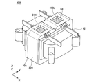
- FIG. 6 shows a reactor 200 of the second embodiment.
- illustration of resin is abbreviate
- a rib 204 is provided on the flange 3
- a closed slit 205 surrounding the entire circumference of the lead wire 12 is provided on the rib 204 (flange 3).
- the size of the slit 205 is substantially equal to the cross-sectional size of the lead wire 12.
- Other configurations are the same as the reactor 100 of the first embodiment.
- the reactor 200 of the second embodiment since the entire circumference of the lead wire 12 is surrounded by the closed slit 205, the molten resin is more effectively prevented from leaking from the side of the lead wire 12 when molding the resin.
- FIG. 7 shows a reactor 300 of the third embodiment.
- a window 341 is provided in the resin 330, and a part of the coil 10a and a part of the coil 10b are exposed from the window 341.
- a heat transfer material is applied to the exposed portion later. This is because the heat of the coil 10a (10b) is released to the outside through the heat transfer material. Since the heat transfer material is also an insulator, the entire coil is finally covered with the insulator.
Abstract
Description
Claims (5)
- ボビンにコイルが巻かれているリアクトルであり、
ボビンのフランジにスリットが設けられており、
コイルのリード線がスリットを通して出ており、
ボビンの一方のフランジから他方のフランジまでコイルが樹脂で覆われている、
ことを特徴とするリアクトル。 - コイルに面しているスリット角部が湾曲していることを特徴とする請求項1に記載のリアクトル。
- リード線は、前記湾曲したスリット角部の形状に沿ってカーブしていることを特徴とする請求項2に記載のリアクトル。
- コイルを覆う樹脂に窓が設けられており、コイルの一部が窓から露出していることを特徴とする請求項1から3のいずれか1項に記載のリアクトル。
- 長手方向で2個の部品に分割されたボビンを用意する工程と、
ボビンの夫々の部品をコイルの夫々の端から嵌める工程と、
ボビンの両端のフランジの間でコイルを覆うように樹脂を成形する工程と、
を備えており、
少なくとも一方のフランジにスリットが設けられており、ボビンの部品を嵌める際にコイルのリード線をそのスリットに通す、
ことを特徴とするリアクトルの製造方法。
Priority Applications (5)
| Application Number | Priority Date | Filing Date | Title |
|---|---|---|---|
| JP2012531584A JP5365745B1 (ja) | 2011-11-04 | 2011-11-04 | リアクトルの製造方法 |
| EP11875123.9A EP2775487A4 (en) | 2011-11-04 | 2011-11-04 | REACTOR AND METHOD FOR PRODUCING THE SAME |
| CN201180057353XA CN103229257A (zh) | 2011-11-04 | 2011-11-04 | 电抗器及其制造方法 |
| US14/237,650 US20140230238A1 (en) | 2011-11-04 | 2011-11-04 | Manufacturing method of reactor (as amended) |
| PCT/JP2011/075472 WO2013065183A1 (ja) | 2011-11-04 | 2011-11-04 | リアクトルおよびその製造方法 |
Applications Claiming Priority (1)
| Application Number | Priority Date | Filing Date | Title |
|---|---|---|---|
| PCT/JP2011/075472 WO2013065183A1 (ja) | 2011-11-04 | 2011-11-04 | リアクトルおよびその製造方法 |
Publications (1)
| Publication Number | Publication Date |
|---|---|
| WO2013065183A1 true WO2013065183A1 (ja) | 2013-05-10 |
Family
ID=48191572
Family Applications (1)
| Application Number | Title | Priority Date | Filing Date |
|---|---|---|---|
| PCT/JP2011/075472 WO2013065183A1 (ja) | 2011-11-04 | 2011-11-04 | リアクトルおよびその製造方法 |
Country Status (5)
| Country | Link |
|---|---|
| US (1) | US20140230238A1 (ja) |
| EP (1) | EP2775487A4 (ja) |
| JP (1) | JP5365745B1 (ja) |
| CN (1) | CN103229257A (ja) |
| WO (1) | WO2013065183A1 (ja) |
Cited By (8)
| Publication number | Priority date | Publication date | Assignee | Title |
|---|---|---|---|---|
| JP2013229406A (ja) * | 2012-04-24 | 2013-11-07 | Tamura Seisakusho Co Ltd | リアクトル |
| JP2015046481A (ja) * | 2013-08-28 | 2015-03-12 | 日立金属株式会社 | リアクトル |
| JP2015103627A (ja) * | 2013-11-22 | 2015-06-04 | 株式会社タムラ製作所 | リアクトル |
| JP2017054847A (ja) * | 2015-09-07 | 2017-03-16 | トヨタ自動車株式会社 | リアクトル |
| JP2018006460A (ja) * | 2016-06-29 | 2018-01-11 | 株式会社トーキン | ラインフィルタ |
| JP2020021806A (ja) * | 2018-07-31 | 2020-02-06 | トヨタ自動車株式会社 | リアクトルの製造方法 |
| US10670171B2 (en) | 2016-10-28 | 2020-06-02 | Panasonic Intellectual Property Management Co., Ltd. | Wiring incorporated resin pipe and method of manufacturing the same |
| JP2020141025A (ja) * | 2019-02-27 | 2020-09-03 | トヨタ自動車株式会社 | リアクトル |
Families Citing this family (9)
| Publication number | Priority date | Publication date | Assignee | Title |
|---|---|---|---|---|
| JP6153900B2 (ja) * | 2014-07-31 | 2017-06-28 | 株式会社タムラ製作所 | リアクトル |
| JP6106645B2 (ja) * | 2014-09-25 | 2017-04-05 | 株式会社タムラ製作所 | リアクトル |
| JP6106646B2 (ja) * | 2014-09-25 | 2017-04-05 | 株式会社タムラ製作所 | リアクトル |
| CN104485200A (zh) * | 2014-12-19 | 2015-04-01 | 上海楚尧电子科技有限公司 | 一种电抗器 |
| JP6570876B2 (ja) * | 2015-05-21 | 2019-09-04 | 株式会社タムラ製作所 | リアクトル |
| CN107786021B (zh) * | 2016-08-29 | 2019-10-11 | 光宝电子(广州)有限公司 | 绝缘套管与绕线制品 |
| JP7017076B2 (ja) * | 2017-12-25 | 2022-02-08 | トヨタ自動車株式会社 | リアクトル |
| WO2023088672A1 (en) * | 2021-11-17 | 2023-05-25 | Sma Solar Technology Ag | Filter-choke, production method thereof and electrical device |
| EP4184533A1 (en) * | 2021-11-17 | 2023-05-24 | SMA Solar Technology AG | Filter-choke, production method thereof and electrical device |
Citations (9)
| Publication number | Priority date | Publication date | Assignee | Title |
|---|---|---|---|---|
| JP2002291186A (ja) * | 2001-03-23 | 2002-10-04 | Nissan Motor Co Ltd | 平角線の巻付け構造および巻付け方法 |
| JP2007180140A (ja) * | 2005-12-27 | 2007-07-12 | Denso Corp | 磁気部品 |
| JP2007200926A (ja) * | 2006-01-23 | 2007-08-09 | Tdk Corp | コイル部品 |
| JP2007250801A (ja) * | 2006-03-15 | 2007-09-27 | Taga Seisakusho:Kk | 巻線端末処理方法および装置 |
| JP2010206104A (ja) * | 2009-03-05 | 2010-09-16 | Sumitomo Electric Ind Ltd | コイル成形体及びリアクトル |
| JP2010226138A (ja) * | 2008-08-22 | 2010-10-07 | Sumitomo Electric Ind Ltd | リアクトル用部品およびリアクトル |
| JP2010245457A (ja) | 2009-04-09 | 2010-10-28 | Sumitomo Electric Ind Ltd | リアクトル及びリアクトル用のボビン |
| JP2010245154A (ja) | 2009-04-02 | 2010-10-28 | Denso Corp | リアクトル |
| JP2011100842A (ja) | 2009-11-05 | 2011-05-19 | Nec Tokin Corp | 磁性素子 |
Family Cites Families (9)
| Publication number | Priority date | Publication date | Assignee | Title |
|---|---|---|---|---|
| JP2569556Y2 (ja) * | 1993-06-30 | 1998-04-28 | ティーディーケイ株式会社 | 大電流チョークコイル |
| US6144280A (en) * | 1996-11-29 | 2000-11-07 | Taiyo Yuden Co., Ltd. | Wire wound electronic component and method of manufacturing the same |
| JP3844170B2 (ja) * | 1998-05-08 | 2006-11-08 | Tdk株式会社 | 箱形ノイズフィルタ |
| US6598824B2 (en) * | 2001-11-20 | 2003-07-29 | Trombetta, Llc | Electrical and mechanical coil system for dual and single action solenoids |
| JP4594238B2 (ja) * | 2003-12-10 | 2010-12-08 | 株式会社タムラ製作所 | トランス |
| JP4513805B2 (ja) * | 2004-03-09 | 2010-07-28 | パナソニック株式会社 | トランス |
| WO2006016554A1 (ja) * | 2004-08-10 | 2006-02-16 | Tamura Corporation | リアクトル |
| JP5428996B2 (ja) * | 2010-03-29 | 2014-02-26 | 株式会社豊田自動織機 | リアクトル |
| JP5932245B2 (ja) * | 2011-06-06 | 2016-06-08 | 株式会社タムラ製作所 | コイル装置用ボビン及びコイル装置 |
-
2011
- 2011-11-04 CN CN201180057353XA patent/CN103229257A/zh active Pending
- 2011-11-04 JP JP2012531584A patent/JP5365745B1/ja active Active
- 2011-11-04 EP EP11875123.9A patent/EP2775487A4/en not_active Withdrawn
- 2011-11-04 WO PCT/JP2011/075472 patent/WO2013065183A1/ja active Application Filing
- 2011-11-04 US US14/237,650 patent/US20140230238A1/en not_active Abandoned
Patent Citations (9)
| Publication number | Priority date | Publication date | Assignee | Title |
|---|---|---|---|---|
| JP2002291186A (ja) * | 2001-03-23 | 2002-10-04 | Nissan Motor Co Ltd | 平角線の巻付け構造および巻付け方法 |
| JP2007180140A (ja) * | 2005-12-27 | 2007-07-12 | Denso Corp | 磁気部品 |
| JP2007200926A (ja) * | 2006-01-23 | 2007-08-09 | Tdk Corp | コイル部品 |
| JP2007250801A (ja) * | 2006-03-15 | 2007-09-27 | Taga Seisakusho:Kk | 巻線端末処理方法および装置 |
| JP2010226138A (ja) * | 2008-08-22 | 2010-10-07 | Sumitomo Electric Ind Ltd | リアクトル用部品およびリアクトル |
| JP2010206104A (ja) * | 2009-03-05 | 2010-09-16 | Sumitomo Electric Ind Ltd | コイル成形体及びリアクトル |
| JP2010245154A (ja) | 2009-04-02 | 2010-10-28 | Denso Corp | リアクトル |
| JP2010245457A (ja) | 2009-04-09 | 2010-10-28 | Sumitomo Electric Ind Ltd | リアクトル及びリアクトル用のボビン |
| JP2011100842A (ja) | 2009-11-05 | 2011-05-19 | Nec Tokin Corp | 磁性素子 |
Non-Patent Citations (1)
| Title |
|---|
| See also references of EP2775487A4 |
Cited By (9)
| Publication number | Priority date | Publication date | Assignee | Title |
|---|---|---|---|---|
| JP2013229406A (ja) * | 2012-04-24 | 2013-11-07 | Tamura Seisakusho Co Ltd | リアクトル |
| JP2015046481A (ja) * | 2013-08-28 | 2015-03-12 | 日立金属株式会社 | リアクトル |
| JP2015103627A (ja) * | 2013-11-22 | 2015-06-04 | 株式会社タムラ製作所 | リアクトル |
| JP2017054847A (ja) * | 2015-09-07 | 2017-03-16 | トヨタ自動車株式会社 | リアクトル |
| JP2018006460A (ja) * | 2016-06-29 | 2018-01-11 | 株式会社トーキン | ラインフィルタ |
| US10670171B2 (en) | 2016-10-28 | 2020-06-02 | Panasonic Intellectual Property Management Co., Ltd. | Wiring incorporated resin pipe and method of manufacturing the same |
| JP2020021806A (ja) * | 2018-07-31 | 2020-02-06 | トヨタ自動車株式会社 | リアクトルの製造方法 |
| JP7049207B2 (ja) | 2018-07-31 | 2022-04-06 | 株式会社デンソー | リアクトルの製造方法 |
| JP2020141025A (ja) * | 2019-02-27 | 2020-09-03 | トヨタ自動車株式会社 | リアクトル |
Also Published As
| Publication number | Publication date |
|---|---|
| EP2775487A4 (en) | 2015-03-04 |
| JPWO2013065183A1 (ja) | 2015-04-02 |
| JP5365745B1 (ja) | 2013-12-11 |
| CN103229257A (zh) | 2013-07-31 |
| US20140230238A1 (en) | 2014-08-21 |
| EP2775487A1 (en) | 2014-09-10 |
Similar Documents
| Publication | Publication Date | Title |
|---|---|---|
| JP5365745B1 (ja) | リアクトルの製造方法 | |
| US10916365B2 (en) | Reactor and reactor manufacturing method | |
| US20140218158A1 (en) | Reactor | |
| JP5697707B2 (ja) | リアクトル | |
| CN103971902B (zh) | 电抗器 | |
| KR100995128B1 (ko) | 코일 중첩형 매립절연변압기 | |
| JP6478065B2 (ja) | リアクトル、およびリアクトルの製造方法 | |
| JP6570876B2 (ja) | リアクトル | |
| JP2010238798A (ja) | 樹脂モールドコア及びリアクトル | |
| JP2006156702A (ja) | トランス | |
| JP6240394B2 (ja) | リアクトル | |
| JP5899926B2 (ja) | リアクトルとその製造方法 | |
| US10811179B2 (en) | Coil component | |
| WO2017135319A1 (ja) | リアクトル | |
| JP2013115140A (ja) | リアクトルおよびその製造方法 | |
| JP7331770B2 (ja) | リアクトルの製造方法及びリアクトル | |
| JP2020061470A (ja) | リアクトルおよびその製造方法 | |
| JP7247847B2 (ja) | リアクトルの製造方法およびリアクトル製造用の金型 | |
| JP2013105854A (ja) | リアクトル | |
| US11145451B2 (en) | Reactor | |
| JP6655209B2 (ja) | リアクトル | |
| KR101130790B1 (ko) | 변압기 및 그 제조방법 | |
| JP2023128802A (ja) | モールドコイル及びリアクトル | |
| JP6762688B2 (ja) | コイル部品 | |
| JP2012235052A (ja) | 線輪部品およびその製造方法 |
Legal Events
| Date | Code | Title | Description |
|---|---|---|---|
| ENP | Entry into the national phase |
Ref document number: 2012531584 Country of ref document: JP Kind code of ref document: A |
|
| REEP | Request for entry into the european phase |
Ref document number: 2011875123 Country of ref document: EP |
|
| WWE | Wipo information: entry into national phase |
Ref document number: 2011875123 Country of ref document: EP |
|
| 121 | Ep: the epo has been informed by wipo that ep was designated in this application |
Ref document number: 11875123 Country of ref document: EP Kind code of ref document: A1 |
|
| WWE | Wipo information: entry into national phase |
Ref document number: 14237650 Country of ref document: US |
|
| NENP | Non-entry into the national phase |
Ref country code: DE |