WO2013061819A1 - 内視鏡システム - Google Patents
内視鏡システム Download PDFInfo
- Publication number
- WO2013061819A1 WO2013061819A1 PCT/JP2012/076658 JP2012076658W WO2013061819A1 WO 2013061819 A1 WO2013061819 A1 WO 2013061819A1 JP 2012076658 W JP2012076658 W JP 2012076658W WO 2013061819 A1 WO2013061819 A1 WO 2013061819A1
- Authority
- WO
- WIPO (PCT)
- Prior art keywords
- image
- endoscope
- observation
- images
- depth
- Prior art date
Links
Images


Classifications
-
- A—HUMAN NECESSITIES
- A61—MEDICAL OR VETERINARY SCIENCE; HYGIENE
- A61B—DIAGNOSIS; SURGERY; IDENTIFICATION
- A61B1/00—Instruments for performing medical examinations of the interior of cavities or tubes of the body by visual or photographical inspection, e.g. endoscopes; Illuminating arrangements therefor
- A61B1/00002—Operational features of endoscopes
- A61B1/00004—Operational features of endoscopes characterised by electronic signal processing
- A61B1/00009—Operational features of endoscopes characterised by electronic signal processing of image signals during a use of endoscope
- A61B1/000095—Operational features of endoscopes characterised by electronic signal processing of image signals during a use of endoscope for image enhancement
-
- A—HUMAN NECESSITIES
- A61—MEDICAL OR VETERINARY SCIENCE; HYGIENE
- A61B—DIAGNOSIS; SURGERY; IDENTIFICATION
- A61B1/00—Instruments for performing medical examinations of the interior of cavities or tubes of the body by visual or photographical inspection, e.g. endoscopes; Illuminating arrangements therefor
- A61B1/00002—Operational features of endoscopes
- A61B1/00043—Operational features of endoscopes provided with output arrangements
- A61B1/00045—Display arrangement
- A61B1/0005—Display arrangement combining images e.g. side-by-side, superimposed or tiled
-
- A—HUMAN NECESSITIES
- A61—MEDICAL OR VETERINARY SCIENCE; HYGIENE
- A61B—DIAGNOSIS; SURGERY; IDENTIFICATION
- A61B1/00—Instruments for performing medical examinations of the interior of cavities or tubes of the body by visual or photographical inspection, e.g. endoscopes; Illuminating arrangements therefor
- A61B1/00064—Constructional details of the endoscope body
- A61B1/00071—Insertion part of the endoscope body
- A61B1/0008—Insertion part of the endoscope body characterised by distal tip features
- A61B1/00096—Optical elements
-
- A—HUMAN NECESSITIES
- A61—MEDICAL OR VETERINARY SCIENCE; HYGIENE
- A61B—DIAGNOSIS; SURGERY; IDENTIFICATION
- A61B1/00—Instruments for performing medical examinations of the interior of cavities or tubes of the body by visual or photographical inspection, e.g. endoscopes; Illuminating arrangements therefor
- A61B1/00163—Optical arrangements
- A61B1/00188—Optical arrangements with focusing or zooming features
-
- A—HUMAN NECESSITIES
- A61—MEDICAL OR VETERINARY SCIENCE; HYGIENE
- A61B—DIAGNOSIS; SURGERY; IDENTIFICATION
- A61B1/00—Instruments for performing medical examinations of the interior of cavities or tubes of the body by visual or photographical inspection, e.g. endoscopes; Illuminating arrangements therefor
- A61B1/04—Instruments for performing medical examinations of the interior of cavities or tubes of the body by visual or photographical inspection, e.g. endoscopes; Illuminating arrangements therefor combined with photographic or television appliances
- A61B1/05—Instruments for performing medical examinations of the interior of cavities or tubes of the body by visual or photographical inspection, e.g. endoscopes; Illuminating arrangements therefor combined with photographic or television appliances characterised by the image sensor, e.g. camera, being in the distal end portion
- A61B1/051—Details of CCD assembly
-
- G—PHYSICS
- G02—OPTICS
- G02B—OPTICAL ELEMENTS, SYSTEMS OR APPARATUS
- G02B23/00—Telescopes, e.g. binoculars; Periscopes; Instruments for viewing the inside of hollow bodies; Viewfinders; Optical aiming or sighting devices
- G02B23/24—Instruments or systems for viewing the inside of hollow bodies, e.g. fibrescopes
- G02B23/2407—Optical details
- G02B23/2423—Optical details of the distal end
- G02B23/243—Objectives for endoscopes
-
- H—ELECTRICITY
- H04—ELECTRIC COMMUNICATION TECHNIQUE
- H04N—PICTORIAL COMMUNICATION, e.g. TELEVISION
- H04N7/00—Television systems
- H04N7/18—Closed-circuit television [CCTV] systems, i.e. systems in which the video signal is not broadcast
- H04N7/181—Closed-circuit television [CCTV] systems, i.e. systems in which the video signal is not broadcast for receiving images from a plurality of remote sources
Definitions
- the present invention relates to an endoscope system that forms an image on two imaging elements of an objective optical system provided in the endoscope.
- At least one image sensor that is shifted from the in-focus position within a range having a common part with a range of depth of field, and extracting a high-frequency signal component from an output signal of the at least one image sensor;
- An image pickup apparatus that performs signal processing to be added to an output signal of an image pickup element arranged at a focus position is disclosed.
- an optical path of light that has passed through an imaging lens that captures images of subjects with different distances is divided into a plurality of optical paths by an optical path dividing unit,
- An image sensor driving device that arranges image sensors with different focus positions on each of the divided optical paths and moves each image sensor along the optical axis direction, and each image sensor according to the input lens parameters of the image lens
- An image pickup apparatus includes an arithmetic processing unit that determines a position on the optical axis of an image and an image composition device that synthesizes a video signal output from each image sensor.
- 2007-313166 as a third conventional example, a focus adjustment mechanism and 2 / pixel pitches shifted in the horizontal and vertical directions are arranged in order to obtain a high-quality image.
- An endoscope that includes a plate imaging unit and in which a vertical pixel pitch of an imaging element and an F number of an objective optical system are set to satisfy predetermined conditions is disclosed.
- the imaging device of the first conventional example when applied to an endoscope, it is premised on that the aperture is sufficiently opened to secure the depth of field, so that a wider field of view from near-field observation to far-field observation is obtained.
- the image pickup apparatus of the second conventional example when applied to an endoscope that requires depth, it is difficult to satisfy the depth of field required for both observation cases.
- the image pickup apparatus of the second conventional example when the image pickup apparatus of the second conventional example is to be mounted on the distal end portion of the endoscope, each image pickup element arranged after the optical path dividing unit is driven in each optical path direction by the image pickup drive apparatus. For this reason, the outer diameter of the distal end portion of the endoscope becomes large, and good insertability required for the endoscope cannot be ensured.
- the third conventional example improves the resolution, and it is difficult to set the depth of field that is required for the close-up observation and the far-view observation.
- the present invention has been made in view of the above-described points, and can be applied to an endoscope that performs close-up observation and distant observation so as to satisfy the required depth of field in the case of close-up observation and remote observation.
- An object of the present invention is to provide an endoscope system that can be used.
- An endoscope system receives an endoscope objective optical system that obtains two optical images with different focus positions with respect to the same subject, and the two optical images with different focus positions.
- Two image sensors for photoelectric conversion an image composition processing unit for synthesizing two images corresponding to the two optical images into one image by the two image sensors, and the endoscope objective optical system.
- a focus switching mechanism that moves the position of the focus switching lens and selectively switches the focus of the endoscope objective optical system to one of the two observation regions of the near observation and the far observation, and the image composition processing unit Synthesizes the two images in each of the observation regions of the close-up observation and the distant observation.
- FIG. 1 is a diagram showing an overall configuration of an endoscope system according to a first embodiment of the present invention.
- FIG. 2A is a diagram showing a configuration of an objective optical system and an image sensor in the first embodiment.
- FIG. 2B is a diagram illustrating a complementary color separation filter attached to the imaging surface of the imaging element.
- FIG. 3 is an explanatory diagram of the depth of field.
- FIG. 4A is a diagram showing a configuration of an image composition processing unit.
- FIG. 4B is a flowchart showing the operation content of the first embodiment.
- FIG. 5 is an explanatory diagram of the action of expanding the depth of field by the focus switching of the objective optical system using the focus lens.
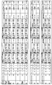
- FIG. 6 is a diagram showing numerical data such as depth of field in the first embodiment in a tabular format.
- FIG. 7 is a diagram illustrating a configuration of an imaging unit in a modification of the first embodiment.
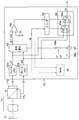
- FIG. 8 is a diagram showing a configuration of a light source device according to the second embodiment of the present invention.
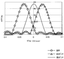
- FIG. 9 shows that two image pickup devices having different focus positions in far-field observation and near-field observation are set so that the depth of field overlaps within the depth range of depth of field having an MTF of 10% or more.
- an endoscope system 1 As shown in FIG. 1, an endoscope system 1 according to a first embodiment of the present invention includes an endoscope 2 that is inserted into a subject, and a light source device 3 that supplies illumination light to the endoscope 2. And a processor device 4 as an image processing device that performs image processing on an imaging unit provided in the endoscope 2 and an image display device 5 that displays an image signal generated by the processor device 4 as an endoscopic image. .
- the endoscope 2 includes an elongated insertion portion 6 to be inserted into a subject and an operation portion 7 provided at the rear end of the insertion portion 6, and illumination light extended from the operation portion 7 is received.
- the light guide connector 9 a at the end of the first cable 9 through which the light guide 8 to be transmitted is inserted is detachably connected to the light source device 3.
- the light source device 3 incorporates a lamp 11 such as a xenon lamp as a light source.
- the light source is not limited to the lamp 11 such as a xenon lamp, and a light emitting diode (abbreviated as LED) may be used.
- the white light generated by the lamp 11 is condensed by the condenser lens 13 after the amount of light passing through the diaphragm 12 is adjusted, and is incident (supplied) on the incident end face of the light guide 8.
- the aperture of the diaphragm 12 is varied by the diaphragm drive unit 14.
- the light guide 8 transmits the illumination light incident on the incident end surface and emits the illumination light from the distal end surface disposed inside the illumination window of the distal end portion 6 a of the insertion portion 6.
- An illumination lens 15 is disposed so as to face the distal end surface, and the illumination lens 15 expands and emits the light emitted from the distal end surface of the light guide 8 from the illumination window, thereby observing the observation target portion inside the subject. Illuminate.
- the illuminated observation target region is divided into two parts arranged on the rear side thereof by an endoscope objective optical system (hereinafter simply referred to as an objective optical system) 16 attached to an observation window provided adjacent to the illumination window.
- An optical image is formed on the image sensors 17a and 17b.
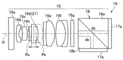
- the objective optical system 16 in the present embodiment includes a plurality of optical elements 16a to 16h arranged along the optical axis O as shown in FIG. 2A, and on the rear side of the optical element 16g and two imaging elements.
- a prism 18 is provided as an optical element that separates two optical images and is arranged on the optical axis O between the two on the front side of 17a and 17b.
- An aperture stop 16h is disposed between the optical elements 16c and 16d.
- the prism 18 is formed, for example, by contacting both inclined surfaces of right-angled triangular prism elements 18a and 18b, and one imaging element 17a is attached near the end face of the prism element 18a (so as to face the end face).
- the other image sensor 17b is attached in the vicinity of the end face of the element 18b (so as to face the end face). Note that the image pickup element 17a and the image pickup element 17b have the same characteristics, and it is preferable to use one having both characteristics.
- the prism 18 separates the light incident through the optical elements 16a to 16h into, for example, an equal amount of reflected light and transmitted light, so that an optical image on the transmitted light side and an optical image on the reflected light side are separated. Separate into optical images.
- the image sensor 17a receives and photoelectrically converts the optical image on the transmitted light side
- the image sensor 17b receives and photoelectrically converts the optical image on the reflected light side.
- the image sensors 17a and 17b are attached near the end faces of the prism elements 18a and 18b, respectively, so that the focus positions are different.
- the optical path length db on the reflected light side is set to be shorter (smaller) than the optical path length (glass path length) da on the transmitted light side to the imaging element 17a in the prism 18.
- the focus position of the image pickup device 17a is relatively shifted (displaced) with respect to the image pickup device 17b
- the image pickup device 17b is shifted with respect to the image pickup device 17a.
- the focus position is relatively shifted to the far point side.
- the optical path lengths to the image sensors 17a and 17b may be changed by making the refractive indexes of the prism elements 18a and 18b different from each other, and the focus positions of the image sensors 17a and 17b may be relatively shifted.
- a complementary color separation filter 20 is attached to each imaging surface of both the imaging elements 17a and 17b.
- magenta Mg, green G, cyan Cy, yellow (yellow) Cy immediately before each pixel arranged at a predetermined pixel pitch (also referred to as pixel size) Pix in the horizontal and vertical directions on the imaging surface.
- the color separation filters 20 composed of the four color filter elements are regularly arranged in the horizontal and vertical directions.
- Mg and G are alternately arranged in the horizontal direction, and are arranged in a cycle of two pixels in the vertical direction.
- Cy and Ye are alternately arranged in the horizontal direction as in the case of Mg and G.
- Cy and Ye are arranged so as to be replaced at a pixel position of two pixels in the vertical direction.
- the primary color filters are represented by R, G, and B
- the objective optical system 16 and the two imaging elements 17a and 17b form an imaging unit 19 that obtains two optical images and acquires two images obtained by photoelectric conversion of the two optical images.
- a focus switching mechanism is provided so that the objective optical system 16 can selectively focus or focus on two observation regions of far-field observation and near-field observation.
- the objective optical system 16 includes a focus lens 21 that can move to two positions Pa and Pb (see FIG. 2A) in the direction of the optical axis O.
- the focus lens 21 includes a focus switching mechanism.
- the actuator 22 is driven so as to move from one position to the other position and from the other position to one position between the two positions Pa and Pb.
- the focus lens 21 is configured by, for example, a cemented lens having a positive power by cementing a concave lens and a convex lens, and the focus lens 21 has a reference numeral 16d on the front side (object side). Is arranged between the aperture stop and the cemented lens 16f, and is selectively selected between two positions Pa and Pb between the position Pa immediately after the aperture stop 16d and the position Pb immediately before the cemented lens 16f. Set to As will be described later with reference to FIG. 5, in the state where the focus lens 21 is set at the front side (object side) position Pa, the subject in the observation area when the image sensor 17a, 17b is used for far-distance observation is focused. Is set to
- the focus is set so that the subject in the observation area when the image pickup devices 17a and 17b perform close observation is focused.
- the focus positions of the image pickup devices 17a and 17b are shifted from each other, and the focus positions are set so as to overlap each other within the range of the depth of field where the MTF (Modulation Transfer Function) is a predetermined value or more as will be described later. Since it is in a state, a synthesized image having a wide depth of field is obtained by synthesizing two images acquired by both the imaging elements 17a and 17b. As shown in FIG.
- the actuator 22 is connected to a signal line 23 inserted through the insertion portion 6, and the signal line 23 is further inserted through the second cable 24 extended from the operation portion 7.
- the signal connector 24 a at the end of the second cable 24 is detachably connected to the processor device 4, and the signal line 23 is connected to an actuator control unit 25 provided in the processor device 4.
- the actuator control unit 25 also receives a switching operation signal from, for example, a switching operation switch 26 provided in the operation unit 7 of the endoscope 2.
- the actuator controller 25 moves the focus lens 21 by applying a drive signal for electrically driving the actuator 22 according to the operation of the switching operation switch 26.
- the switching operation means for generating the switching operation signal is not limited to the switching operation switch 26 but may be a switching operation lever or the like.
- the focus lens 21, the actuator 22, and the actuator control unit 25 form a focus switching mechanism.
- the image pickup devices 17a and 17b are connected to the insertion portion 6, the operation portion 7, and the signal lines 27a and 27b inserted through the second cable 24, and the signal connector 24a is connected to the processor device 4, whereby the processor device. 4 is connected to an image processor 30 serving as an image processing unit provided in 4.
- the image processor 30 includes an image reading unit 31 that reads out image signals (simply abbreviated as “images”) of images picked up by two image pickup devices 17 a and 17 b having different focus positions and photoelectrically converted, and the image reading unit 31.
- An image correction processing unit 32 that performs image correction on the two read images and an image composition processing unit 33 that performs image composition processing for combining the two corrected images.
- the image correction processing unit 32 includes a relative magnification difference, a position difference, a rotation difference, and a brightness difference in each of the images formed on the imaging surfaces of the two imaging elements 17a and 17b. Are performed by image processing on the two images photoelectrically converted by the imaging elements 17a and 17b so as to match each other.
- the image correction processing unit 32 corrects the above-described geometric difference and brightness difference.
- the image or image having the lower luminance of the two images or images, or the lower luminance of the two images or images at the relatively same position is used as a reference. Make corrections. There may be a difference in brightness (luminance value) when the same subject is imaged due to a sensitivity difference between the imaging chips of the two imaging elements 17a and 17b, a manufacturing error of an on-chip lens, or the like.
- the brightness correction is performed so as to match with a relatively brighter one, that is, a luminance signal (for example, G signal) having a lower intensity (signal level).
- a luminance signal for example, G signal
- the brightness correction is performed so that the gain is decreased (or attenuated) so that the lower brightness is used as a reference and the higher brightness is matched with the lower brightness as the reference. The deterioration of the image quality of the composite image due to the deterioration of N can be prevented.
- the image composition processing unit 33 compares the contrast in each of the spatially identical pixel regions in the two images, and selects the pixel region having a relatively high contrast, thereby synthesizing the two images. A composite image as one image is generated. When the contrast difference between the two images is small, a composite image is generated by composite image processing that adds each image with a predetermined weight.
- FIG. 4A shows a configuration example of the image composition processing unit 33 that performs such image composition processing.
- the objective optical system 16 forms two optical images on the imaging surfaces of the two CCDs 17a and 17b having different focus positions.
- the first and second image data photoelectrically converted by the CCDs 17a and 17b and passed through the image correction processing unit 32 and the like (based on the imaging of the CCDs 17a and 17b, respectively) are two frame memories 62a and 62b in the image composition processing unit 33. Are stored in pixel units.
- the first image data and the second image data corresponding to the same part are stored in the memory cell having the same address. Is done.
- a known luminance signal may be generated from the R, G, and B color components, and the same processing may be performed according to the comparison result of the contrast of the two luminance signals.
- the signals si1 and si2 of the first image and the second image simultaneously read from the two frame memories 62a and 62b by designating the same address are input to the difference calculation circuit 63 configured by a differential amplifier or the like. Then, the difference calculation circuit 63 calculates the difference amount between the signals si1 and si2, for example, by subtracting the luminance value of the second image from the luminance value of the first image. Further, the difference calculation circuit 63 determines that the luminance level of any image is higher (larger) than the other based on the positive or negative polarity of the difference amount, and outputs a binary signal sp. For example, if the polarity is positive, si1> si2, and if it is negative, si1 ⁇ si2.
- of the difference amount calculated by the difference calculation circuit 63 is input to the comparison circuit 64, and the comparison circuit determines whether or not the absolute value
- the comparison circuit 64 is H level when the absolute value
- the binary signal of the comparison circuit 64 and the binary signal sp corresponding to the polarity by the difference calculation circuit 63 are input to the decoder 65, and the decoder 65 is configured to switch the two switching circuits constituting the selection circuit 66 from the two binary signals. The switching of the circuits 66a and 66b is controlled.
- Signals si1 and si2 are respectively input to the contacts a and b of the switching circuit 66a, and a signal from the common contact c of the switching circuit 66a and a signal from the adder 67 are input to the contacts a and b of the switching circuit 66b.
- the composite signal sc that has been subjected to image composition processing is output from the common contact c of the switching circuit 66b.
- the adder 67 adds the signals si1 and si2 and outputs them to the contact b of the switching circuit 66b.
- the decoder 65 selects the contact a of the switching circuit 66b, and the absolute value
- the decoder 65 selects the contact point a or b of the switching circuit 66a according to the binary signal sp of polarity. Specifically, when the binary signal sp is at the H level, the signal si1 is selected (selected state indicated by a solid line in FIG.
- the switching circuit 66a selects an image portion having a higher contrast when the contrast difference is greater than or equal to a predetermined value.
- the two signals si1 and si2 are added and output as a composite signal.
- the difference calculation circuit 62 calculates the difference amount between the two signals si1 and si2. If the absolute value
- the switching circuit 66b selects the signal added by the adder 67 and outputs this signal as the combined signal sc.
- the combined signal sc is generated by weighting as follows. You may make it do. As shown by dotted lines in FIG. 4A, multipliers 68a and 68b are arranged on the two input sides of the adder 67. The multipliers 68a and 68b are weighted coefficients c1 and c2 output from the signals si1 and si2 and the ROM 69, respectively. And are output to the adder 67.
- the ROM 69 stores weighting coefficients c1 and c2 that are set in advance according to the difference amount.
- the ROM 69 uses the absolute value
- the weighting coefficients c1 and c2 to be multiplied by si2 are output.
- the weighting coefficients c1 and c2 stored in the ROM 69 are such that as the absolute value
- the adder 67 adds the signals si1 and si2 multiplied by the weighting coefficients c1 and c2, respectively, and outputs the result as a combined signal sc.
- the image processor 30 outputs a post-stage image processed image and a post-stage image processing section 34 that performs post-stage image processing such as contour enhancement and gamma correction on one image synthesized by the image synthesis processing section 33.
- An image output unit 35 is provided, and an image output from the image output unit 35 is output to the image display device 5.
- the image processor 30 includes a dimming unit 36 that generates a dimming signal for dimming to a reference brightness from the image read by the image reading unit 31, and the dimming unit 36 generates the dimming signal.
- the dimming signal is output to the aperture driving unit 14 of the light source device 3.
- the aperture drive unit 14 adjusts the aperture amount of the aperture 12 so as to maintain the reference brightness according to the dimming signal.
- the image correction processing unit 32 is provided with a correction parameter storage unit 37 that stores correction parameters (information) used when correcting an image.
- Each endoscope 2 has an ID memory 38 in which endoscope identification information (endoscope ID) unique to the endoscope 2 is stored, and a unique correction parameter to be corrected in the endoscope 2.
- a correction parameter storage unit 37 that stores correction parameters corresponding to the endoscope 2 is provided.
- a correction parameter storage unit 37 that stores correction parameters is provided in, for example, the ID memory 38 in the endoscope 2.
- the correction parameter storage unit 37 is not limited to the case where the correction parameter storage unit 37 is provided in the ID memory 38, and may be provided in a memory different from the ID memory 38.
- the control unit 39 of the processor 30 identifies the presence / absence of correction by the endoscope ID provided on the endoscope 2 side.
- the correction parameter is read from the correction parameter storage unit 37 and the correction parameter is sent to the image correction processing unit 32.
- the image correction processing unit 32 performs image correction corresponding to the imaging unit 19 mounted on each endoscope 2 based on the correction parameter transferred from the control unit 39. Further, the image correction processing unit 32 performs image correction using the correction parameter, such as correction of the above-described magnification difference and position difference, using one of the two images or one of the images as a reference image or reference image. .
- magnification shift occurs between two images
- the specification of the objective optical system 16 is used.
- the telecentricity is lost and a design is made such that light rays are incident on the imaging elements 17a and 17b obliquely. For example, if the angle formed with the optical axis is the incident angle, the clockwise angle is positive and the counterclockwise direction is negative, the design is such that the negative incident angle is obtained. If the focus position is shifted in the objective optical system in which such telecentricity is lost, a magnification shift occurs between the two images.
- the deviation amount is stored in the correction parameter storage unit 37 in advance, and when the target endoscope 2 is connected to the processor device 4, the endoscope 2 is It recognizes and calls the corresponding parameter from the correction parameter storage unit 37 to perform correction.
- the imaging unit 19 when the imaging unit 19 is assembled, the relative pixel positions of the two images may be slightly shifted.
- the amount of deviation at the time of manufacture is stored in the correction parameter storage unit 37, and the deviation correction is performed by the image correction processing unit 32.
- the positional deviation correction is performed, for example, by correcting the reading position of the two images so that the relative positions of the image captured by the imaging element 17a and the image captured by the imaging element 17b match. After the positional deviation is corrected, it is output to the image composition processing unit 33.
- correction may be performed using an adjustment reference chart prepared separately when using the endoscope.
- the reference chart may be arranged at a desired position on the distal end portion 6a of the endoscope 2, and the image correction processing unit 32 may read the deviation between the two images with respect to the reference chart and correct the deviation.
- the control unit 39 should drive the actuator control unit 25 even when the focus lens 21 constituting the objective optical system 16 mounted on each endoscope 2 is driven at a different position. Position information is sent, and the actuator control unit 25 performs control to appropriately drive the actuator 22 even when the type of the endoscope 2 is different.
- FIG. 3 is an explanatory diagram of the depth of field determined geometrically.
- an imaging device having a pixel pitch Pix shown in FIG. 3 is arranged at an image plane position X ′ using an objective optical system (focal length Fl) when the best distance is X. think of. If the object is brought close to (from X) to Xn under the condition where the image pickup device is fixed, the image plane position Xn ′ at the time of proximity will deviate from the image pickup surface position of the image pickup device.
- the best distance is X
- the distance to the depth of field near point is Xn
- the distance to the depth of field far point is Xf
- the allowable circle of confusion is ⁇
- the focal length of the objective optical system is Fl.
- the effective F number of the objective optical system is Fno.
- the depth of field can be expanded by the composite image compared to the case of the depth of field determined geometrically, but even if the influence of diffraction cannot be ignored, the field of view is determined by the composite image.
- the depth can be expanded. It is generally known that when the imaging device is further miniaturized and the number of pixels is increased, the influence of wave optics cannot be ignored when defining the depth of field. This is because, at the focal position, the spot size is broadened due to the influence of diffraction from the spot size defined geometrically, so that a deviation occurs from the geometric optical depth of field calculation.
- the diffraction has an effect that cannot be ignored.
- the image pickup devices 17a and 17b of the present embodiment are also regularly arranged with the same pixel pitch Pix in the horizontal direction and the vertical direction as in the case of the image pickup device shown in FIG.
- the imaging unit 19 using the imaging elements 17a and 17b described above is set so as to obtain the characteristics shown in the table of FIG.
- Composite far depth depth of field of the composite image at the time of far-field observation
- near1 depth depth of field by the image pickup device 17a at the time of close-up observation
- near2 depth depth of field by the image pickup device 17b at the time of close-up observation
- Synthesized near depth depth of field (range) of synthesized image during close-up observation
- Near depth width depth width from near end of synthesized near depth to far end of synthesized near depth
- imaging method total pixels Numerical data of the number (total number of pixels of the image sensor) is shown.
- BST indicates the best distance as the object distance when the MTF is maximum.
- the following shows the outline.
- the image pickup devices 17a and 17b complementary color solid-state image pickup devices having 1 million pixels (103580 pixels) and a pixel (pixel) size of 1.7 ⁇ m are employed.
- two image sensors 17a The vertical pixel size of 17b is set such that Pix is 1.70 ⁇ m, the resolution coefficient k1 as a correction parameter is 3.00, the F value margin k2 is 1.00, and the effective F number Fno of the objective optical system 16 is 7.65. ing.
- the imaging unit 19 has the following condition 2.4 ⁇ Fno / Pix ⁇ 4.5 (5) It is set to satisfy.
- the condition of the formula (5) is as follows.
- k1 ⁇ Pix 1.22 ⁇ ⁇ ⁇ Fno (9) It becomes.
- the effective F number Fno set in the objective optical system 16 needs to have a certain margin so that the optical performance can be sufficiently exhibited in consideration of manufacturing variations and the like.
- the coefficient k2 is within a reasonable range of about 0.7 ⁇ k2 ⁇ 1.
- the expression (11) can be expressed by the following expression (12) when expressed as a relationship between the effective F number Fno and the pixel size Pix.
- the effective F number Fno of the objective optical system 16 becomes too small to obtain a desired depth of field.
- the depth of field is sufficient, but the imager's Pix size is large and the resolution is low.
- the resolution is improved by increasing the number of pixels, but the imager size increases. Therefore, when the objective optical system 16 is enlarged and mounted on the distal end portion 6a of the endoscope 2, the outer diameter does not increase (insertability). Is not preferable).
- the value exceeds the upper limit of the range of the expression (5) the effective F number Fno of the objective optical system becomes too large to obtain a desired brightness.
- the imaging unit 19 is a complementary color system and is a simultaneous type.
- the coefficient k1 is generally set to about 3.
- the endoscope system 1 having such a configuration is different from the objective optical system 16 as an endoscope objective optical system for obtaining two optical images having different focus positions with respect to the same subject, and the focus positions are different from each other.
- Two image sensors 17a and 17b that receive and optically convert two optical images, and an image composition process for synthesizing two images corresponding to the two optical images into one image by the two image sensors 17a and 17b.
- the position of the focus lens 21 as a focus switching lens provided in the endoscope objective optical system is moved to one of the two observation areas of the near observation and the far observation, and the endoscope objective optical system And an actuator 22 that constitutes a focus switching mechanism that selectively switches the focus, and the image composition processing unit 33 performs the 2 in each of the observation areas of the near observation and the far observation. Wherein the synthesizing of the images.
- the operation of the present embodiment in the case where an operator as a user performs endoscopic examination of a body cavity using the endoscope 2 will be described.
- the endoscope 2 is connected to the light source device 3 and the processor device 4, and the operator turns on the power.
- the control unit 39 performs control to set the far side to the setting state with the observation region.
- the control unit 39 regards the switching operation switch 26 in this initial setting state as a setting state in which a signal for setting the far side as the observation region is output to the control unit 39.
- step S2 the control unit 39 drives the focus lens 21 via the actuator control unit 25 and the actuator 22, so that the objective optical system 16 uses the far side as the observation region.
- the image correction processing unit 32 corrects two images by the two image pickup devices 17a and 17b using correction parameters.
- the image composition processing unit 33 generates a synthesized image for the two images corrected by the image correction processing unit 32, and outputs the synthesized image to the image display device 5 side.
- the image display device 5 displays a composite image.
- FIG. 5A shows the imaging state of the imaging unit 19 corresponding to step S2.
- FIG. 5A shows how the objective optical system 16 forms an image on the imaging elements 17a and 17b in a state in which the focus lens 21 is set so that the objective optical system 16 is focused on a distant observation region.
- FIG. 5A shows the objective optical system 16 corresponding to the state in which the focus lens 21 is set (switched) to the front position Pa, and a prism 18 for separating the optical image into two optical images is arranged on the imaging side.
- the two optical images are received by the image pickup devices 17a and 17b attached to the respective end faces, and photoelectrically converted signals are output.
- the depth of field is expanded as follows by the composite image obtained by the two image sensors 17a and 17b.
- the glass path lengths to the imaging devices 17a and 17b in the prism 18 are different, and images of images having relatively different focus positions are acquired by the imaging devices 17a and 17b.
- images of images having relatively different focus positions are acquired by the imaging devices 17a and 17b.
- an image focused on the (far) far point side is formed on the image sensor 17b
- an image focused on the closer side relative to the image sensor 17b is formed on the image sensor 17a. Imaged.
- the imaging unit 19 (the objective optical system 16 and the imaging devices 17a and 17b) is set so that the depth end on the far point side of the field depth Xaf overlaps.
- the depth of field for images formed on the image sensors 17a and 17b is Xaf and Xbf.
- the image is synthesized by the image synthesis processing unit 33
- the depth of field corresponding to the synthesized image in the state of focusing on the distant observation is set as the synthesized depth of field.
- Xaf + Xbf can be obtained as the combined depth of field.
- one composite depth of field is obtained by composite image processing in which each image is added with a predetermined weight. That is, the combined depth of field is obtained as Xaf + Xbf (6.54 mm to 128.59 mm).
- endoscopic examination can be performed smoothly if such a wide combined depth of field Xaf + Xbf is obtained.
- Xaf + Xbf a wide combined depth of field
- only a narrow depth of field can be obtained, for example, the near point side portion in the image obtained during screening may become blurred, and endoscopy is performed smoothly. It becomes difficult.
- step S5 of FIG. 4B the control unit 39 monitors whether or not the switching operation switch 26 has been operated by the operator, and if not, returns to the process of step S5.
- the operator operates the switching operation switch 26 when the screening is finished and the diagnosis is to be performed closer.
- the control unit 39 proceeds to the process of step S6.
- step S6 the control unit 39 performs control to set the observation region on the near side.
- the control unit 39 drives the focus lens 21 via the actuator control unit 25 and the actuator 22 to bring the objective optical system 16 into a setting state in which the near point side is in focus so that the close side is the observation region.
- step S7 the image correction processing unit 32 corrects the two images by the two imaging elements 17a and 17b using the correction parameter. However, if there is no large difference in the correction amount in step S6 with respect to step S2, it is not necessary to newly perform correction as the same parameter.
- step S8 the image composition processing unit 33 generates a synthesized image for the two images corrected by the image correction processing unit 32, and outputs the synthesized image to the image display device 5 side.
- the image display device 5 displays a composite image.
- FIG. 5B shows an imaging state of the imaging unit 19 corresponding to step S6.
- FIG. 5B is an explanatory diagram corresponding to a state in which the focus lens 21 is set (switched) to the position Pb on the rear side in FIG. .
- the depth of field can be expanded by the composite image obtained by the two image pickup devices 17a and 17b as follows as in the case of FIG. Assuming that the depth of field at the image sensor 17a is Xan and the depth of field at the image sensor 17b is Xbn, the depth end on the near point side of the depth of field Xbn and the far side of the depth of field Xan.
- the image pickup unit 19 (the objective optical system 16 and the image pickup devices 17a and 17b) is set so as to overlap the depth end.
- the depth of field corresponding to the synthesized image in the state of focusing on the observation area of the close-up observation is set as the synthesized depth of field. In this case, Xan + Xbn can be obtained as the combined depth of field.
- the state of close-up observation in which close observation is performed is set.
- a wide synthetic depth of field Xan + Xbn can be obtained while maintaining a high resolving power, so that the details of the lesion can be clearly observed and diagnosis can be performed smoothly.
- the combined depth of field Xaf + Xbf (range) in the case of far-field observation and the combined depth of field in the case of close-up observation Xan + Xbn (range) is set to overlap. For this reason, in the present embodiment, when the remote observation state and the close-up observation state are switched, it is possible to observe without generating an unclear (blurred) observation region between the two observation states. The surgeon can smoothly perform endoscopy.
- step S9 the control unit 39 determines whether or not an instruction operation for ending the endoscopic examination has been performed. When the inspection is finished and the end instruction operation is not performed, it is determined whether or not the switching operation switch 26 is operated in the next step S10.
- step S10 the process of step S10 is continued. If the switching operation switch 26 is operated, the process returns to step S2, the observation area is set to the far side, and the above-described operation. repeat.
- the depth of field can be expanded when the observation area is set on either the far side or the near side.
- the present embodiment can be applied to an endoscope that performs close-up observation and far-distance observation (that is, can be mounted on the distal end portion 6a of the insertion portion 6 of the endoscope 2).
- An endoscope system that can satisfy the required depth of field can be provided.
- a desired depth of field can be obtained, and the size can be reduced to a size that can be mounted on the distal end portion 6a of the endoscope 2, and a desired size can be obtained. Brightness can be secured and degradation of resolution can be prevented.
- the objective optical system 16 that obtains two optical images with different focus positions may be telecentric in which the principal ray is parallel to the optical axis (or a diaphragm is disposed at the position of the rear focal point of the objective optical system 16). . If the objective optical system 16 is telecentric, a magnification shift due to the focus position does not occur, so that correction by image processing is unnecessary and an image processing algorithm for generating a composite image can be simplified, which is preferable. When the objective optical system 16 mounted on the distal end portion 6a of the insertion portion 6 of the endoscope 2 is aimed at miniaturization, the telecentricity of the objective optical system 16 may be destroyed.
- the objective optical system 16 that obtains two optical images with different focus positions to set the incident angle of light that forms an image on the imaging surfaces of the imaging elements 17a and 17b to be less than 10 degrees.
- the prism 18 using the prism elements 18a and 18b having the right triangular prism shape is used as the optical element for separating the two images, but as shown in FIG. It may be configured.
- the prism 54 constituting the objective optical system 51 in FIG. 7 includes a first prism 54a to which an image sensor 17a that receives transmitted light is attached, and a second prism 54b to which an image sensor 17b that receives reflected light is attached. Become.
- An imaging unit 53 is formed by the objective optical system 51 and the imaging elements 17a and 17b.
- the objective optical system 51 excluding the prism 54 includes optical elements 52a to 52f, and the optical element 52c forms the focus lens 21. Note that an aperture stop 52f is disposed between the optical elements 52c and 52d.
- a dielectric film that functions as a half mirror is (mirror) coated on the joint surface M1 of the second prism 54b formed of a pentaprism with the first prism 54a. . Then, about half (50%) of the light incident along the optical axis O of the objective optical system 51 is transmitted through this connection surface, and an optical image is formed on the imaging surface of the image sensor 17a.
- a reflection surface coated with a dielectric film is formed on the reflected light side end face M2 so as to be almost totally reflected, and after the second reflection on this reflection surface
- the image sensor 17b attached to the end face facing the reflected light receives the light.
- the coating of the end face M2 may be a metal coating such as Al-SiO2 or Ag-SiO2.
- an optical image is formed on the image sensor 17b after one reflection, that is, an odd number of reflections, so that it becomes a mirror image and image processing for inverting the mirror image in the processor device 4 is performed.
- the correction of the mirror image by the optical even number of reflections may increase the size of the objective optical system and the cost of the prism, the correction of the mirror image by the odd number of reflections as shown in FIG. At 32, mirror image inversion is performed.
- it may be configured to reflect optically even times as shown in FIG.
- second to sixth embodiments using image sensors and the like different from the above-described embodiments will be sequentially described.
- the endoscope system according to the second embodiment is a frame sequential type endoscope system, and brightness is prioritized as can be understood from the following numerical data, and a bright image can be acquired.
- This endoscope system employs a light source device 3B in the endoscope system 1 of FIG. 1 in which the light source device generates frame-sequential illumination light as shown in FIG.
- the rotary filter 55 is arranged in the illumination optical path between the lamp 11 and the diaphragm 12 in the light source device 3 of FIG. 1, and the rotary filter 55 is rotated by the motor 56.
- the rotary filter 55 is provided with fan-shaped R, G, and B filters that selectively transmit red (R), green (G), and blue (B) light, respectively. In the configuration of FIG. By passing the rotary filter 55, it is possible to supply the light guide 8 with R, G, B plane sequential illumination light.
- the image reading unit 31 in the processor device 4 of FIG. 1 temporarily stores the images read in the frame sequential order, and simultaneously reads out the frame memory for generating the synchronized color image.
- the simultaneous type that is, the image pickup device including the color separation filter is used, but the image pickup unit mounted on the distal end portion 6a of the insertion portion 6 of the endoscope 2 in this embodiment is configured.
- the imaging device two monochrome imaging devices 61a and 61b are employed.
- the vertical pixel size of the two imaging elements 61a and 61b is 1.45 ⁇ m
- the resolving power coefficient k1 is a correction parameter. 2.00
- the F value margin k2 is set to 0.80
- the effective F number Fno of the objective optical system is set to 3.48.
- it is a field sequential method using a monochrome imaging element of 860,000 pixels and 1.45 ⁇ m pixels, and it takes a large margin for the diffraction limit Fno and is set with more emphasis on brightness. .
- Fno / Pix 2.40. More detailed numerical data is shown in the table of FIG.
- FIG. 6A data including the case of the embodiment in which priority is given to the brightness satisfying the condition of the above-described formula (5), 2.4 ⁇ Fno / Pix ⁇ 4.5 is shown.
- FIG. 6B an embodiment emphasizing depth expansion that satisfies the condition of formula (5) ′ described later, 2.7 ⁇ Fno / Pix ⁇ 4.5 (implementation of the second ′) Data in the case of (form).
- This embodiment can be similarly applied to the case of the frame sequential method, and has the same effect as that of the first embodiment.
- the depth of field can be expanded when the observation area is set on either the far side or the near side.
- the present embodiment can be applied to an endoscope that performs close-up observation and far-distance observation (that is, can be mounted on the distal end portion 6a of the insertion portion 6 of the endoscope 2).
- An endoscope system that can satisfy the required depth of field can be provided.
- the third to sixth embodiments described below have substantially the same effects as the first embodiment.
- the endoscope system of the present embodiment is a simultaneous endoscope system as in the first embodiment.
- complementary color separation filters are employed as the two imaging elements 17a and 17b of the imaging unit 19, but in this embodiment, primary color separation filters are employed.
- a simultaneous imaging device with a primary color Bayer array of 1.5 million pixels and 1.1 ⁇ m pixels is used, and a relatively small diameter (the imaging size is small because it is a minute pixel) and an ultra-high pixel endoscope is implemented. It has a form.
- the absolute depth range is narrower than the first embodiment and the second embodiment, an endoscopic image with a smaller diameter and higher image quality can be provided while maintaining a practical depth of field.
- the vertical pixel size of the two imaging elements is Pix of 1.1 ⁇ m, and the resolution coefficient k1 as a correction parameter is 2.80.
- the F value margin k2 is set to 1.0, and the effective F number Fno of the objective optical system is set to 4.62.
- Fno / Pix 4.20. More detailed numerical data is shown in the table of FIG.
- This embodiment has the same effect as that of the first embodiment.
- the endoscope system according to the present embodiment corresponds to a modification of the third embodiment.
- the endoscope system of the present embodiment has 1.5 million pixels as in the third embodiment, but the image sensor has a pixel size of 1.45 ⁇ m and a large opening, which has a relatively large margin for noise and brightness. The setting is considered.
- a deep depth of field can be obtained as a composite image while preventing the resolution from being lowered with respect to the third embodiment.
- the vertical pixel size of the two imaging elements is Pix of 1.45 ⁇ m, and the resolution coefficient k1 as a correction parameter is 2.80.
- the F value margin k2 is set to 1.0, and the effective F number Fno of the objective optical system is set to 6.09.
- Fno / Pix 4.20. More detailed numerical data is shown in the table of FIG.
- This embodiment has the same effect as that of the first embodiment.
- the endoscope system according to the present embodiment corresponds to a modification of the third embodiment.
- the endoscope system of the present embodiment uses a primary imager with a primary color Bayer arrangement of 1.2 million pixels and 1.1 ⁇ m pixels, and is aimed at a relatively high pixel and a smaller diameter than the third embodiment.
- priority is given to depth rather than resolving power, and observation is performed so that close-up observation side can perform close-up observation while maintaining the practical level, although the resolving power slightly deteriorates beyond the diffraction limit Fno.
- the distance is set to a depth of field that can approach 3mm.
- it gives priority to close-up observation but has a combined depth of field that ensures a depth of 3 mm so that there is no hindrance to endoscopy.
- the vertical pixel size of the two imaging elements is Pix of 1.10 ⁇ m, and the resolution coefficient k1 as a correction parameter is 2.80.
- the F value margin k2 is set to 1.0
- the effective F number Fno of the objective optical system is set to 4.62.
- Fno / Pix 4.20. More detailed numerical data is shown in the table of FIG. This embodiment has the same effect as that of the first embodiment.
- the endoscope system according to the present embodiment corresponds to a modification of the third embodiment.
- the endoscope system according to the present embodiment uses a simultaneous image pickup device having a primary color Bayer array of 1 million pixels and 1.7 ⁇ m pixels, gives priority to the brightness at the time of observation over the depth of field, and has a wide coverage as a composite image. The depth of field is obtained.
- the vertical pixel size of the two imaging elements is Pix of 1.70 ⁇ m, and the resolution coefficient k1 as a correction parameter is 2.80.
- the F value margin k2 is set to 1.0
- the effective F number Fno of the objective optical system is set to 7.14.
- Fno / Pix 4.20. More detailed numerical data is shown in the table of FIG. This embodiment has the same effect as that of the first embodiment.
- k2 is made small so that there is a margin in brightness. Things tend to be difficult.
- the possible range of k2 is considered to be realistic from 0.9 to 1.0 on the assumption that the diffraction limit Fno is not exceeded.
- Fno diffraction limit
- CMOS sensor is used as an imaging device for an endoscope because of requirements such as a large number of pixels due to pixel miniaturization, low power consumption and low cost. May increase in the future.
- pixel miniaturization may cause degradation of S / N, etc.
- endoscopes where thinning is preferable it may be possible to select a fine cell size CMOS for smaller diameter and smaller size. It is done.
- the CMOS sensor of the primary color Bayer array is assumed in the embodiment of the present application.
- the third to sixth embodiments are the targets, and the expression (5) ′ is further 2.97 ⁇ Fno / Pix ⁇ 4.2 (5) ′′ It becomes. Therefore, when emphasizing the depth of field and adopting a primary color Bayer-type CMOS sensor as the image sensor, a sufficient depth of field can be obtained even if (5) ′′ (see the table in FIG. 6C). (Refer to (5) ′′ lower limit data according to the fourth embodiment and (5) ′′ upper limit data according to the third embodiment).
- each depth end has an MTF of 10% or more and overlaps.
- Fi 1 / k1 / Pix (5) It is. If the MTF of defocus in this Fi is about 10%, it is possible to judge that the image is not visible in the subjective evaluation based on experience, and can be seen. In other words, if the MTF is about 10% or more, it can be considered within the depth of field.
- the condition for maximizing the depth range is that the MTF is maintained at about 10% at each depth end. This is shown in FIG. In the case where the MTF characteristics are set so as to have the focus position shifted from the near point side to the far point side as indicated by ⁇ and ⁇ from the reference MTF characteristic indicated by the solid line in FIG. In the embodiment (both in the combined depth of field on the far-viewing side at the time of two-focus switching and the combined depth of field on the close-up viewing side), the overlapping occurs at the depth edge of the hem where the MTF is 10% or more. Yes.
- a composite image synthesized with overlapping at the depth end of the bottom where the MTF is 10% or more has a desirable composite depth of field without generating a depth gap.
- the first to sixth embodiments described above satisfy this condition.
- a depth gap portion where the MTF is less than 10% is included within the combined depth of field, and an image is displayed at the depth gap portion. This results in a blurred observation area where the image becomes blurred.
- an endoscope system having a wide depth of field that can be clearly observed over a wide range without generating an unclear observation region even when two focal points are switched.
- the setting is made so that the combined depth of field on the far-viewing side at the time of two-focus switching and the combined depth of field on the near-viewing side overlap (first to third and sixth embodiments).
- a setting may be made such that a depth gap is generated without the continuous observation side combined depth of field and the close observation side combined depth of field being continuously connected (N ⁇ ). F gap).
- the reference image sensor may be set to an image sensor that is focused on the far point side. If it does in this way, it has an effect which adjustment on a manufacture side is easy to perform.
- a) remote focus adjustment (out of focus) is such that the image position is closer to the object side than the imaging surface (the direction in which the imaging device is extended).
- b) near point focus adjustment is such that the image position is closer to the hand side than the imaging surface (the direction in which the imaging element is pulled).
- the order of performing b) after a) is good. If the focus adjustment is performed in the order in which a) is performed after b), the lens may collide during the focus adjustment of the image sensor on the far point side after b). In this case, the focus adjustment b) must be performed again. That is, the focus adjustment of the near-point image sensor can be performed more smoothly with reference to the far-point image sensor that can fix the focus adjustment condition by focus adjustment first. In this case, in addition to focus adjustment, image correction such as geometric correction (position and rotation) excluding magnification and brightness can be performed more smoothly.
- the objective optical system 16 and the like are switched between two focal points between the far-field observation state and the near-field observation state.
- the present invention is not limited to the two-point focus switching, and may be configured to switch the focus (position) of multiple points such as three points and four points. Further, embodiments configured by partially combining the above-described embodiments and the like also belong to the present invention.
Landscapes
- Health & Medical Sciences (AREA)
- Life Sciences & Earth Sciences (AREA)
- Surgery (AREA)
- Physics & Mathematics (AREA)
- Engineering & Computer Science (AREA)
- Optics & Photonics (AREA)
- Radiology & Medical Imaging (AREA)
- Veterinary Medicine (AREA)
- Biophysics (AREA)
- Pathology (AREA)
- Nuclear Medicine, Radiotherapy & Molecular Imaging (AREA)
- Public Health (AREA)
- Biomedical Technology (AREA)
- Heart & Thoracic Surgery (AREA)
- Medical Informatics (AREA)
- Molecular Biology (AREA)
- Animal Behavior & Ethology (AREA)
- General Health & Medical Sciences (AREA)
- Signal Processing (AREA)
- Astronomy & Astrophysics (AREA)
- General Physics & Mathematics (AREA)
- Multimedia (AREA)
- Endoscopes (AREA)
Abstract
Description
また、撮像素子の高画素化に伴い、被写界深度は一般的に狭くなるため、これに対応する種々の提案がある。
第1の従来例としての日本国特開平9-116807号公報には、合焦位置に配置した撮像素子に対して、被写界深度の範囲が該合焦位置に配置した撮像素子の被写界深度の範囲と共通部分を有する範囲内で合焦位置からずらして配置した少なくとも1つの撮像素子を配置して、該少なくとも1つの撮像素子の出力信号から高域信号成分を抽出して、前記合焦位置に配置した撮像素子の出力信号に加算する信号処理を行う撮像装置が開示されている。
なお、第3の従来例としての日本国特開2007-313166号公報には、高画質の画像をえるためにフォーカス調整機構と、水平・垂直方向に約1/2ピッチ画素ずらして配置した2板撮像ユニットを備え、撮像素子の垂直方向画素ピッチと対物光学系のFナンバーとを所定の条件を満たすように設定した内視鏡が開示されている。
また、第2の従来例の撮像装置を、内視鏡の先端部に搭載しようとした場合、光路分割手段後に配置される各撮像素子を撮像駆動装置によって、各光路方向に駆動する構成となるため、内視鏡先端部の外径が大きくなり、内視鏡に求められる良好な挿入性を確保できない。
本発明は上述した点に鑑みてなされたもので、近接観察及び遠方観察を行う内視鏡に適用でき、近接観察の場合及び遠方観察の場合にそれぞれ必要とされる被写界深度を満たすようにできる内視鏡システムを提供することを目的とする。
(第1の実施形態)
図1に示すように本発明の第1の実施形態の内視鏡システム1は、被検体内に挿入される内視鏡2と、この内視鏡2に照明光を供給する光源装置3と、内視鏡2に設けられた撮像手段に対する画像処理を行う画像処理装置としてのプロセッサ装置4と、プロセッサ装置4により生成された画像信号を内視鏡画像として表示する画像表示装置5とを有する。
内視鏡2は、被検体内に挿入される細長の挿入部6と、この挿入部6の後端に設けられた操作部7とを有し、操作部7から延出された照明光を伝送するライトガイド8が挿通された第1のケーブル9の端部のライトガイドコネクタ9aは、光源装置3に着脱自在に接続される。
上記ライトガイド8は、入射端面に入射された照明光を伝送して、挿入部6の先端部6aの照明窓の内側に配置された先端面から出射する。この先端面に対向して照明レンズ15が配置されており、照明レンズ15はライトガイド8の先端面から出射された光を照明窓から拡開して出射し、被検体内部の観察対象部位を照明する。
本実施形態における対物光学系16は、図2Aに示すようにその光軸O上に沿って配置した複数の光学素子16a~16hを有すると共に、光学素子16gの後方側で、かつ2つの撮像素子17a,17bの前方側となる両者の間の光軸O上に配置された、2つの光学像に分離する光学素子としてのプリズム18を備える。なお、光学素子16cと16dとの間に明るさ絞り16hが配置されている。
プリズム18は、光学素子16a~16hを経て入射される光を、例えば等量の反射光と透過光とに分離することにより、透過光側の光学像と反射光側の光学像との2つの光学像に分離する。撮像素子17aは透過光側の光学像を受光して光電変換し、撮像素子17bは反射光側の光学像を受光して光電変換する。
なお、プリズム素子18aと18bにおける両者の屈折率を異ならせることにより、撮像素子17a、17bに至る光路長を変え、両撮像素子17a,17bによるピント位置を相対的にずらすようにしても良い。
Mg,Gは、水平方向に交互に配置され、また垂直方向には2画素分の周期で配置されている。一方、Cy,Yeは、水平方向には、Mg,Gの場合と同様に交互に配置されているが、垂直方向には2画素おいた画素位置において置換するようにした配置となっている。
なお、原色フィルタをR,G,Bで表すと、色透過特性の機能として、Mg=R+B、Cy=G+B、Ye=R+Gのような関係となる。
また、本実施形態においては、対物光学系16により、遠方観察と近接観察の2つの観察領域にピント又は焦点を選択的に合わせられるように焦点切替機構を設けている。 具体的には、対物光学系16は、その光軸Oの方向における2つの位置Pa,Pb(図2A参照)に移動可能なフォーカスレンズ21を有し、このフォーカスレンズ21は、焦点切替機構を構成するアクチュエータ22により、2つの位置Pa,Pb間で一方の位置から他方の位置、他方の位置から一方の位置に移動するように駆動される。
なお、図5にて後述するように、フォーカスレンズ21を前方側(物体側)の位置Paに設定した状態においては撮像素子17a、17bにより遠方観察する場合の観察領域の被写体にピントが合うように設定されている。
そして、両撮像素子17a、17bでのピント位置が互いにずらしてあり、各ピント位置は後述するようにMTF(Modulation Transfer Function)が所定の値以上となる各被写界深度の範囲内で重なる設定状態であるので、両撮像素子17a、17bで取得した2つの画像を合成することにより、広い被写界深度を有する合成画像が得られるようにしている。
図1に示すようにアクチュエータ22は、挿入部6内を挿通された信号線23と接続され、この信号線23はさらに操作部7から延出された第2のケーブル24内を挿通される。この第2のケーブル24の端部の信号コネクタ24aは、プロセッサ装置4に着脱自在に接続され、上記信号線23は、プロセッサ装置4内に設けたアクチュエータ制御部25に接続される。
なお、切替操作信号を発生する切替操作手段は、切替操作スイッチ26に限らず、切替操作レバー等でも良い。上記フォーカスレンズ21と、アクチュエータ22と、アクチュエータ制御部25とにより、焦点切替機構が形成される。
上記撮像素子17a,17bは挿入部6、操作部7、第2のケーブル24内を挿通された信号線27a,27bと接続され、信号コネクタ24aがプロセッサ装置4に接続されることにより、プロセッサ装置4内に設けた画像処理部としての画像プロセッサ30と接続される。
画像補正処理部32は、2つの撮像素子17a,17bの撮像面にそれぞれ結像される夫々の像における相対的な倍率の差異と、位置の差異と、回転の差異と、明るさの差異とを、それぞれ合致させるように、撮像素子17a,17bにより光電変換された2つの画像に対して画像処理により行う。
2つの撮像素子17a,17bの撮像面にそれぞれ結像される夫々の像は、相対的に倍率ズレ、位置ズレ、回転方向のズレが発生したり、2つの撮像素子17a,17bの感度差などから明るさの差異が生じる場合がある。これらの差異を製造時などにおいて、完全に解消する事は難しい。しかし、それらのズレ量が大きくなると、合成画像が2重画像となったり、不自然な明るさムラ等が生じてしまう。このため、本実施形態では、画像補正処理部32にて上述した幾何的な差異、明るさ差異を補正する。
2つの撮像素子17a,17bの各撮像チップにおける感度差やオンチップレンズの製造誤差等で同じ被写体を撮像した場合の明るさ(輝度値)に差異が生じる場合がある。
上記のように輝度の低い方を基準にし、輝度の高い方を基準となる輝度の低い方の輝度に合わせるようにゲインを低下(または減衰)させるような明るさ補正を行うことにより、S/Nの劣化による合成画像の画質の低下を防止できるようにしている。
図4Aはこのような画像合成処理を行う画像合成処理部33の構成例を示す。同一の被写体61に対して、対物光学系16は、ピント位置が異なる2つのCCD17a,17bの撮像面に2つの光学像を結像する。CCD17a,17bにより光電変換され、画像補正処理部32等を経た(CCD17a、17bの撮像にそれぞれ基づく)第1及び第2の画像データは、画像合成処理部33内の2つのフレームメモリ62a,62bに画素単位で格納される。
また、本実施形態においては、画像補正処理部32において、画像を補正する場合に使用する補正パラメータ(の情報)を格納した補正パラメータ格納部37を設けている。
図1に示す構成例では、内視鏡2における例えばIDメモリ38内に、補正パラメータを格納した補正パラメータ格納部37を設けている。
なお、補正すべき固有の補正パラメータがない場合には、補正パラメータ格納部37を設けることが不必要になる。また、補正パラメータ格納部37をIDメモリ38の内部に設ける場合に限定されるものでなく、IDメモリ38と別のメモリに設けるようにしても良い。
そして、プロセッサ30の制御部39は補正の有無を内視鏡2側に設けた内視鏡IDで識別して、補正有りの場合には内視鏡2側に格納されているIDメモリ38内の補正パラメータ格納部37から補正パラメータを読み取り、この補正パラメータを画像補正処理部32に送る。
画像補正処理部32は、制御部39から転送された上記補正パラメータに基いて各内視鏡2に搭載された撮像ユニット19に対応した画像補正を行う。
また、画像補正処理部32は、補正パラメータを用いて、2つの像または画像における1つを基準像または基準画像として上述した倍率の差異の補正、位置の差異の補正等、画像の補正を行う。
対物光学系16のサイズを比較的小さくしようとした場合、テレセントリック性を崩して撮像素子17a,17bへの光線が斜めに入射するような設計が行なわれる場合がある。例えば、光軸とのなす角を入射角として、時計回りをプラス、反時計回りをマイナスとすると、マイナスの入射角となるような設計が行なわれる。
この様なテレセントリック性が崩れた対物光学系でピント位置をズラすと2つの画像間で倍率ズレが生じる事になる。
また、撮像ユニット19の組立て時に2つの画像の相対的な画素の位置が微小にズレる場合がある。この場合、製造時のズレ量を補正パラメータ格納部37に格納しておき、画像補正処理部32にてそのズレ補正を行なう様にする。
位置のズレ補正は例えば撮像素17aで撮像された画像と撮像素子17bで撮像された画像との相対的な位置が合致するように2つの画像の読出し位置を修正する様な処理が行なわれ、位置ズレが補正された後、画像合成処理部33に出力される。
また、制御部39は、アクチュエータ制御部25に対して、各内視鏡2に搭載された対物光学系16を構成するフォーカスレンズ21の駆動すべき位置が異なるような場合においても、駆動すべき位置の情報を送り、アクチュエータ制御部25は内視鏡2の種類が異なるような場合にもアクチュエータ22を適切に駆動する制御を行う。
また、本明細書における被写界深度の定義を、図3等を参照して以下に説明する。
図3は幾何光学的に決まる被写界深度の説明図を示す。
一般的な内視鏡において、ベスト距離をXとした場合の対物光学系(その焦点距離Fl)を用いて像面位置X'に、図3中に示す画素ピッチPixの撮像素子を配置した場合を考える。撮像素子を固定した条件において、物体を(Xから)Xnまで近接すると、近接時の像面位置Xn'は、撮像素子の撮像面位置からずれることになる。
即ち、錯乱円径がδと一致するまでの範囲を近点側の被写界深度と定義することができる。
1/Xn - 1/X = δFno/Fl2…(1)
物体を(Xから)遠点側にXfまで移動した場合を考えることにより、同様に被写界深度の遠点側での式も以下のように定義される。
1/X - 1/Xf = δFno/Fl2… (2)
(1)式と(2)式を合わせると、
1/Xn - 1/Xf = 2δFno/Fl2… (3)
となる。そして、焦点深度dに対応した被写界深度がXn-Xfとなる。
ただし、上記のようにベスト距離をX、被写界深度近点までの距離をXn、被写界深度遠点までの距離をXf、許容錯乱円径をδ、対物光学系の焦点距離をFl、対物光学系の有効FナンバーをFnoとしている。
以上は幾何光学的に決まる一般的な被写界深度の定義である。
撮像素子をより微細化し、高画素化していくと被写界深度を定義する際には、波動光学的な影響が無視できない事が一般的に知られている。これは焦点位置において、幾何光学的に定義したスポットサイズから、回折の影響からスポットサイズが広がるため幾何光学的な被写界深度の計算からズレが生じるためである。従って、本実施形態のような回折限界に近い有効FナンバーFnoまで絞られるケースが多い多画素の撮像素子を搭載した内視鏡2では、回折が無視できない影響となる。なお、本実施形態の撮像素子17a,17bも図3に示した撮像素子の場合と同様に水平方向及び垂直方向に同じ画素ピッチPixで規則的に画素が配置されている。
Fi=1/k1・Pix …(4)
となる。
このFiにおけるデフオーカスのMTF(Modulation Transfer Function)が約10%あれば、主観評価では像のボケは認識できず「見えている」と判断できる。
言い換えると、MTFは約IO%となるデフオーカス位置が深度端と見なす事ができる。
本明細書では波動光学的な被写界深度端をFi=1/k1・Pixとした際の評価空間周波数にて評価したMTFの10%を深度端として定義している。
また、本実施形態においては、上述した撮像素子17a,17bを用いた撮像ユニット19として図6の表に示すような特性が得られるように設定している。
また、本実施形態においては、波長λ=0.5461μmの光に対して、2つの撮像素子17a.17bの垂直方向ピクセルサイズをPixが1.70μm、補正パラメータとしての解像力係数k1を3.00,F値マージンk2を1.00,対物光学系16の有効FナンバーFnoを7.65に設定している。
λ 0.5461
Pix 1.70
KI 3.00
k2 1.00
Fno 7.65
そして、本実施形態の撮像ユニット19は、以下の条件
2.4≦Fno/Pix≦4.5 …(5)
を満たすように設定している。(5)式の条件は、以下のような理由による。
この限界は、Rayleighにより、2つの点像が接近した時、別々の像として識別できる限界の距離として規定されており、λを光の波長、有効FナンバーをFnoとすると、1.22・λ・Fnoで表される。2つの点像の分離限界の距離、つまり分解能Rは、
R=1.22・λ・Fno …(6)
となる。
R=2・Pix …(7)
現実的には、採用する撮像方式における補間方法や電気系の特性に影響されるため、分解能Rは、任意の係数k1を用いて以下のように表される。
R=k1・Pix …(8)
係数k1は、撮像素子の性能を十分に引き出す必要があるため一般的には2≦k1≦3程度となる。
k1 ・Pix=1.22・λ・Fno …(9)
となる。また、対物光学系16に設定される有効FナンバーFnoは、製造バラツキなどを考慮して光学性能を十分に発揮できるようにある程度余裕を持たせる必要がある。
従って、Rayleigh限界式で規定される有効FナンバーFnoは、実際には任意の係数k2を考慮して設定される。つまり、
kl・Pix=1.22・λ・Fno・k2 …(10)
のように設定される。尚、係数k2は、対物光学系16のサイズや被写界深度とのバランスを考慮すると、0.7≦k2≦1程度が妥当な範囲となる。
ただし、撮像素子の性能が活かされる前提で、多少の解像力劣化を許容して被写界深度の拡大を優先する場合は、0.7≦k2≦1.2程度に設定しても構わない。
(9)式、(10)式より設定すべき対物光学系16の有効FナンバーFnoは、
Fno=Fno*k2=(1/1.22・λ)・Pix・k1 …(11)
となる。
ここで(11)式を有効FナンバーFnoと、ピクセルサイズPixの関係で示すと以下の(12)式で示せる。
Fno/Pix=(1/1.22・λ)・k1・k2 …(12)
高画素の撮像素子を用いた内視鏡システムにおいては、上述した
2.4≦Fno/Pix≦4.5 …(5)
である事が望ましい。
また、反対に(5)式の範囲の上限を超えて大きくなると、対物光学系の有効FナンバーFnoが大きくなりすぎて所望の明るさが得られない。
同時に回折限界を大き<越えてしまう、もしくは妥当な補間方式でないために解像力の劣化が生じてしまう。
本実施形態における上述した図6の表に示す設定においては、撮像ユニット19は補色系で同時式であり、この場合には係数k1を3程度にすることが一般的である。また、ピクセルサイズが1.7μmで画素の補色系の同時式撮像素子を用い、対物光学系16の回折限界Fナンバーからのマージン係数k2をk2=1として(12)式より
Fno/Pix=4.5 …(13)
となる。
図1に示すように内視鏡2を光源装置3と、プロセッサ装置4に接続して、術者は電源をONする。
図4Bにおける最初のステップS1の初期設定として、制御部39は、遠方側を観察領域とする設定状態にする制御を行う。そして、制御部39は、この初期設定の状態における切替操作スイッチ26が遠方側を観察領域とする信号を制御部39に出力する設定状態であると見なす。
また、この場合、ステップS3に示すように画像補正処理部32は、2つの撮像素子17a、17bによる2つの画像を、補正パラメータを用いて補正する。
また、ステップS4に示すように、この画像補正処理部32により補正された2つの画像に対して、画像合成処理部33は、合成した合成画像を生成し、画像表示装置5側に出力し、画像表示装置5は、合成画像を表示する。
図5(A)は、ステップS2に対応する撮像ユニット19の撮像状態を示す。
図5(A)は、フォーカスレンズ21を前方側の位置Paに設定(切替)した状態に対応した対物光学系16を示し、その結像側に2つの光学像に分離するプリズム18が配置され、各端面に取り付けた撮像素子17a,17bにより2つの光学像を受光し、それぞれ光電変換した信号を出力する。
この遠方観察の状態において、2つの撮像素子17a,17bにより得られる合成画像により、以下のように被写界深度を拡大する。
例えば、撮像素子17bには、(遠方)遠点側にピントが合った像が結像され、撮像素子17aには、撮像素子17bに対して相対的により近接側にピントが合った像が結像される。
この遠方の観察領域の場合における撮像素子17aでの被写界深度をXaf、撮像素子17bでの被写界深度をXbfとすると、被写界深度Xbfの近点側の深度端と、被写界深度Xafの遠点側の深度端とが重なるように撮像ユニット19(の対物光学系16と撮像素子17a,17b)が設定されている。
また、図1、図4Aの画像合成処理部33による画像合成処理により合成した場合には遠方観察にピントを合わせた状態での合成画像の場合に対応する被写界深度を合成被写界深度とした場合、その合成被写界深度としてXaf+Xbfを得ることができる。但し、重なり部分においては(コントラスト差が小さい領域)、各画像に所定の重み付けして加算する合成画像処理により一つの合成被写界深度を得る。つまり、合成被写界深度は、Xaf+Xbf(6.54mm~128.59mm)を得る。
これに対して、狭い被写界深度しか得られない場合には、スクリーニング中に得られる画像における例えば近点側部分が不鮮明となる可能性が発生してしまい、内視鏡検査を円滑に行い難くなる。
術者は、スクリーニングを終了して、より近接して診断を行おうとする場合には、切替操作スイッチ26を操作する。
切替操作スイッチ26が操作された場合には制御部39は、ステップS6の処理に進む。ステップS6において、制御部39は、観察領域を近接側に設定する制御を行う。制御部39は、アクチュエータ制御部25、アクチュエータ22を介してフォーカスレンズ21を駆動し、対物光学系16が近接側を観察領域とするように近点側にピントがあった設定状態にする。
図5(B)は、ステップS6に対応する撮像ユニット19の撮像状態を示す。
図5(B)は、図5(A)においてフォーカスレンズ21を後方側の位置Pbに設定(切替)して近接観察する観察領域にピント(焦点)を合わせた状態に対応した説明図である。
撮像素子17aでの被写界深度をXan、撮像素子17bでの被写界深度をXbnとすると、被写界深度Xbnの近点側の深度端と、被写界深度Xanの遠点側の深度端とが重なるように撮像ユニット19(の対物光学系16と撮像素子17a,17b)が設定されている。
また、図1の画像合成処理部33による画像合成処理により合成した場合には近接観察の観察領域にピントを合わせた状態での合成画像の場合に対応する被写界深度を合成被写界深度とした場合、その合成被写界深度としてXan+Xbnを得ることができる。
本実施形態においては高い解像力を保ちつつ広い合成被写界深度Xan+Xbnを得ることができるので、病変の詳細を鮮明に観察でき、診断を円滑に行うことができる。
また、本実施形態においては、図5(A)及び図5(B)に示すように遠方観察の場合の合成被写界深度Xaf+Xbf(の範囲)と、近接観察の場合の合成被写界深度Xan+Xbn(の範囲)とが重なるように設定されている。このため、本実施形態においては、遠方観察の状態と近接観察の状態とを切り替えた場合において、両観察状態における中間に不鮮明となる(ぼける)観察領域が発生することなく観察することができるため、術者は内視鏡検査を円滑に行うことができる。
図4Bにおいて、ステップS8の次のステップS9において制御部39は、内視鏡検査を終了の指示操作が行われたか否かを判定し、終了の指示操作が行われた場合には内視鏡検査を終了し、終了の指示操作がされていない場合には次のステップS10において切替操作スイッチ26が操作されたか否かを判定する。
このような動作を行う本実施形態によれば、遠方側及び近接側のいずれの観察領域に設定した場合にも、被写界深度を拡大できる。
また、本実施形態は、近接観察及び遠方観察を行う内視鏡に適用でき(つまり、内視鏡2の挿入部6の先端部6aに搭載でき)、近接観察の場合及び遠方観察の場合にそれぞれ必要とされる被写界深度を満たすようにできる内視鏡システムを提供できる。
また、上述した(5)式を満たすように設定することにより、所望とする被写界深度を得られ、かつ内視鏡2の先端部6aに搭載可能な小型のサイズにでき、また所望の明るさを確保できると共に、解像力の劣化を防止できる。
対物光学系16がテレセントリックであれば、ピント位置による倍率ズレは生じないため、画像処理による補正が不必要になり合成画像を生成する画像処理アルゴリズムの簡略化ができ、好ましい。
内視鏡2の挿入部6の先端部6aに搭載する対物光学系16として、その小型化を狙う場合には、対物光学系16のテレセントリック性を崩してもよい。しかしながら、撮像素子17a、17bの撮像面への入射角をあまり大きくする、ピント位置による倍率差が大きくなり、上述の画像補正処理による補正量が大きくなり、画質の劣化が生じ易くなり、好ましくない。
図7における対物光学系51を構成するプリズム54は、透過光を受光する撮像素子17aが取り付けられた第1プリズム54aと、反射光を受光する撮像素子17bが取り付けられた第2プリズム54bとからなる。この対物光学系51と撮像素子17a、17bとにより撮像ユニット53が形成される。
図7に示す対物光学系51においては、ペンタプリズムにより構成される第2プリズム54bにおける、第1プリズム54aとの接合面M1は、ハーフミラーとして機能する誘電体膜が(ミラー)コーティングされている。
そして、対物光学系51の光軸Oに沿って入射した光は、この接続面において約半分(50%)が透過して撮像素子17aの撮像面に光学像を結び、残りの約半分が1回目の反射がされた後、反射光側の端面M2には、ほぼ全反射するように誘電体膜が(ミラー)コーティングされた反射面が形成され、この反射面で2回目の反射された後、この反射光に対向する端面に取り付けられた撮像素子17bにより受光される。尚、端面M2のコーティングはAl‐SiO2やAg-SiO2等の金属コーティングとしても良い。
このため、この鏡像を反転させる画像処理が不要となるため、処理がより簡単になると共に、反転させる画像処理による画質の劣化も発生しない。但し、アナログの画像をデジタルの画像に変換してメモリに一時的に格納した画像の場合には、メモリから読み出す場合のアドレスを変更することにより、反転した画像を容易に生成できるため、このような場合には、画質の劣化は殆ど発生しない。
光学的な偶数回の反射による鏡像の補正は対物光学系の大型化やプリズムのコスト高となる可能性があるので、図2のような奇数回の反射による鏡像の補正は、画像補正処理部32にて鏡像反転により行なう。
当然、対物光学系16の大型化やコスト面に問題がなければ、図7に示すように光学的に偶数回反射させる構成にしても良い。
次に上述した実施形態と異なる撮像素子等を用いた第2~第6実施形態を順次説明する。
第2の実施形態の内視鏡システムは、面順次方式の内視鏡システムであり、以下の数値データからも分かるように明るさを優先させており、明るい画像を取得できる構成にしている。
本内視鏡システムは、図1の内視鏡システム1において、光源装置が図8に示すように面順次の照明光を生成する光源装置3Bを採用する。図8の光源装置3Bは、図1の光源装置3において、ランプ11と絞り12との間の照明光路中に回転フィルタ55が配置され、この回転フィルタ55はモータ56により回転される。
回転フィルタ55には、赤(R),緑(G),青(B)の光を選択的にそれぞれ透過するR,G,Bフィルタが扇形状に設けてあり、図1の構成において、さらに回転フィルタ55を通すことにより、ライトガイド8にR,G,Bの面順次の照明光を供給することができおる。
また、第1の実施形態では同時式、つまり色分離フィルタを備えた撮像素子を用いていたが、本実施形態における内視鏡2の挿入部6の先端部6aに搭載される撮像ユニットを構成する撮像素子は、モノクロの2つの撮像素子61a,61bを採用する。
この場合における撮像ユニットの数値データとしては、波長λ=0.5461μmの光に対して、2つの撮像素子61a,61bの垂直方向ピクセルサイズをPixが1.45μm、補正パラメータとしての解像力係数k1を2.00,F値マージンk2を0.80,対物光学系の有効FナンバーFnoを3.48に設定している。この実施形態の特徴としては、86万画素1.45μmピクセルのモノクロ撮像素子を使った面順次方式であり、回折限界Fnoに対して余裕マージンを多く取り、より明るさを重視した設定となっている。
より詳細な数値データは、図6の表において示している。なお、図6(A)の表においては、上述の(5)式の条件、2.4≦Fno/Pix≦4.5 を満たす明るさを優先した実施形態の場合も含めたデータを示す。また、図6(B)の表においては、後述する(5)′式の条件、2.7≦Fno/Pix≦4.5 を満たす深度拡大に重点を置いた実施形態(第2′の実施形態)の場合のデータを示す。また、図6(C)の表においては、後述する(5)″式の条件、3≦Fno/Pix≦4.2(より厳密には2.97≦Fno/Pix≦4.2)を満たす原色ベイヤの同時式に限定し、深度拡大に絞った下限範囲の実施形態の場合のデータを示す。
また、本実施形態は、近接観察及び遠方観察を行う内視鏡に適用でき(つまり、内視鏡2の挿入部6の先端部6aに搭載でき)、近接観察の場合及び遠方観察の場合にそれぞれ必要とされる被写界深度を満たすようにできる内視鏡システムを提供できる。
以下に説明する第3の実施形態-第6の実施形態も第1の実施形態とほぼ同様の効果を有する。
本実施形態の内視鏡システムは、第1の実施形態と同様に、同時式の内視鏡システムである。第1の実施形態においては、撮像ユニット19の2つの撮像素子17a,17bとして、補色系の色分離フィルタを採用していたが、本実施形態においては原色の色分離フィルタを採用している。この実施形態の特徴としては、150万画素1.1μmピクセルの原色ベイヤ配列の同時式撮像素子を使い、比較的、細径(微小ピクセルなので撮像サイズが小さい)で且つ超高画素内視鏡の実施形態となっている。第1の実施形態,第2の実施形態に対して絶対値的な深度幅は狭いが、実用上の被写界深度を保ちつつ、より細径で高画質な内視鏡画像を提供できる。
この場合における撮像ユニットの数値データとしては、波長λ=0.5461μmの光に対して、2つの撮像素子の垂直方向ピクセルサイズをPixが1.1μm、補正パラメータとしての解像力係数k1を2.80,F値マージンk2を1.0,対物光学系の有効FナンバーFnoを4.62に設定している。
より詳細な数値データは、図6の表において示している。
本実施形態の内視鏡システムは、第3の実施形態の変形例に相当する。本実施形態の内視鏡システムは、第3の実施形態と同様の150万画素であるが、撮像素子のピクセルサイズを1.45μmとして開口を大きく取り、ノイズや明るさに対して比較的余裕を考慮した設定になっている。この際、原色ベイヤ配列における補間方法をより最適化する事で、第3の実施形に対して解像力が低下しない様にしつつ、合成画像としては深い被写界深度を得られるようにしている。
この場合における撮像ユニットの数値データとしては、波長λ=0.5461μmの光に対して、2つの撮像素子の垂直方向ピクセルサイズをPixが1.45μm、補正パラメータとしての解像力係数k1を2.80,F値マージンk2を1.0,対物光学系の有効FナンバーFnoを6.09に設定している。
より詳細な数値データは、図6の表において示している。
本実施形態の内視鏡システムは、第3の実施形態の変形例に相当する。本実施形態の内視鏡システムは、120万画素1.1μmピクセルの原色ベイヤ配列の同時式撮像素子を使い、比較的高画素で且つ第3の実施形態より細径を狙っている。また、より絞って解像力よりも深度優先した実施形態であり、解像力は回折限界Fnoを越えて多少劣化するものの実用レベルを保ちつつ、近接観察側はより近接して拡大観察が出来るように、観察距離は3mmまで近接できる様な被写界深度の設定になっている。また、拡大観察を優先して近接するが深度幅は3mmを確保するような合成被写界深度を得ているので内視鏡検査に支障がない様にしている。
そして、本実施形態の撮像ユニットは、Fno/Pix=4.20となる。
より詳細な数値データは、図6の表において示している。
本実施形態は、第1の実施形態の場合と同様の効果を有する。
本実施形態の内視鏡システムは、第3の実施形態の変形例に相当する。本実施形態の内視鏡システムは、100万画素1.7μmピクセルの原色ベイヤ配列の同時式撮像素子を使い、被写界深度よりも観察時の明るさを優先させつつ、合成画像としては広い被写界深度を得られるようにしている。
そして、本実施形態の撮像ユニットは、Fno/Pix=4.20となる。
より詳細な数値データは、図6の表において示している。
本実施形態は、第1の実施形態の場合と同様の効果を有する。
この場合は、k2の取り得る範囲は、回折限界Fnoを超えない前提においては0.9~1.0までが現実的と考えられる。例えば、観察系の明るさにある程度余裕を持った設定とした第2の実施形態で考えると、k2=0.9とするとFno/Pix=2.7となる。尚、本願の実施形態で考えると、上限値は第1の実施形態となる。従って、高画素化を狙い観察系の明るさよりも被写界深度の確保を重視する場合は、
2.7≦Fno/Pix≦4.5 ・・・(5)′
としても良い(図6(B)の表の第2′の実施形態による(5)′の下限データ、第1の実施形態による(5)′の上限データ参照)。この場合、十分な合成被写界深度を得られるものの、明るさが不足する分は撮像素子に裏面照射型CMOSセンサを採用したり、プロセッサ装置4の図示しないノイズリダクション機能の最適化により、より大きなゲインを掛けるような工夫が考えられる。また、内視鏡先端径に余裕があればライトガイドを増やして総合的な明るさを補っても構わない。
一方で、ピクセルの微細化はS/Nの劣化なども想定されるものの細径化が好ましい内視鏡においては、より細径、小型化のために微細セルサイズのCMOSを選択する場合も考えられる。この際、補間方法の最適化をしても結果として解像力の低下はある程度想定され、任意の係数k1は補色方式よりは小さくできるもののk1=2.8程度となる可能性もある。つまり、原色ベイヤ配列のCMOSセンサにおいては現実的には2.2≦k1≦2.8程度になると考えられる。
2.97≦Fno/Pix≦4.2 ・・・(5)″
となる。従って、被写界深度を重視し且つ撮像素子に原色ベイヤ配列のCMOSセンサを採用する際は(5)″としても十分な被写界深度を得る事ができる(図6(C)の表の第4の実施形態による(5)″の下限データ、第3′の実施形態による(5)″の上限データ参照)。
Fi=1/k1・Pix …(5)
である。このFiにおけるデフォーカスのMTFが約10%あれば、経験上の主観評価では像のボケは認識できず「見えている」と判断できる。言い換えると、MTFは約10%以上あれば被写界深度内と見なせる。
図9において実線で示す基準のMTF特性のものから△と○とで示すように近点側と遠点側とにピント位置がずれた状態のMTF特性を有するように設定した場合、上述した各実施形態において(2焦点切替時の遠方観察側の合成被写界深度と、近接観察側の合成被写界深度とのいずれにおいても)、MTFが10%以上となる裾の深度端で重なっている。
これに対して、仮にMTFがIO%未満となる深度端の状態で合成すると、その合成被写界深度範囲内において、MTFが10%未満となる深度ギャップ部分を含み、その深度ギャップ部分で画像が不鮮明となるボケる(ボケて見える)観察領域が生じてしまうことになる。
なお、2焦点切替時の遠方観察側の合成被写界深度と、近接観察側の合成被写界深度の深度端は重なるような設定にする(第1-第3,第6の実施形態)と、遠方観察から近接観察に切り替えた場合、両者の間で不鮮明となる領域が発生しないで鮮明に観察できるため、スクリーニングや詳細観察を円滑に行い易い。
一方、第4,第5の実施形態のように、遠方観察側合成被写界深度と近接観察側合成被写界深度が連続的に繋がらずに、深度ギャップを生じさせる設定でも良い(N-Fギャップ有り)。
このような設定にすることでより近接した拡大観察が可能となるため、拡大内視鏡を主としたユーザーにはより目的に適した内視鏡を提供できる。
但し、2焦点切替時の視野角変動が殆ど生じないフォーカシングであり、内視鏡の操作性を考慮して深度幅は3mm前後を確保している事が望ましい。
ところで、上述した実施形態において、基準とする撮像素子は遠点側にピントを合わせた撮像素子に設定しても良い。このようにすると、製造面での調整が行い易い効果を有する。
具体的には、a)遠方のピント調整(ピント出し)は、像位置が撮像面より物体側に来る(撮像素子を繰り出す方向)となる。
b)の次にa)を行う順番でピント調整を行うと、b)後における遠点側の撮像素子のピント調整時に、レンズがぶつかってしまう可能性がある。この場合には、再度b)のピント調整を行わなければならなくなる。
つまり、最初にピント調整によりそのピント調整の条件を固定できる遠点側の撮像素子を基準にして、近点側の撮像素子のピント調整する方が、円滑に行うことができる。 また、このようにした場合、ピント調整の他に、倍率、明るさを除く幾何補正(位置、回転)等の像補正もより円滑に行うことができる。
また、上述した実施形態等を部分的に組み合わせる等して構成される実施形態も本発明に属する。
Claims (15)
- 同一の被写体に対してピント位置が異なる2つの光学像を得る内視鏡対物光学系と、
前記ピント位置が異なる前記2つの光学像を受光し、光電変換する2つの撮像素子と、
前記2つの撮像素子により前記2つの光学像に対応する2つの画像を1つの画像に合成する画像合成処理部と、
前記内視鏡対物光学系に設けた焦点切替用レンズの位置を移動し、近接観察と遠方観察の2つの観察領域の一方に前記内視鏡対物光学系の焦点を選択的に切り替える焦点切替機構と、を備え、
前記画像合成処理部は、前記近接観察と前記遠方観察の各観察領域の夫々において、前記2つの画像を合成することを特徴とする内視鏡システム。 - 前記内視鏡対物光学系と前記2つの撮像素子は、内視鏡対物光学系の有効FナンバーをFno、前記2つの撮像素子の撮像面に2次元的に配置されたピクセルのピクセルピッチをPixと表した場合、
以下の条件
2.4≦Fno/Pix≦4.5
を満たすことを特徴とする請求項1に記載の内視鏡システム。 - 前記ピント位置が異なる2つの光学像を得る内視鏡対物光学系は、
前記ピント位置が異なる2つの光学像を受光する2つの撮像素子との間に、像を2つに分離する光学素子が配置され、
前記像を2つに分離する前記光学素子は少なくとも一方の光学像を1回以上反射させる反射面を含み、
前記反射面で反射された像を前記撮像素子の1つに結像させることを特徴とする前記請求項1の内視鏡システム。 - 前記2つの撮像素子からの夫々の像における相対的な倍率の差異と、位置の差異と、回転の差異と、明るさの差異とを、合致させる画像処理を行う画像補正処理部を備え、
前記画像合成処理部は、前記画像補正処理部で補正された夫々の画像を1つに合成することを特徴とする前記請求項1の内視鏡システム。 - 前記画像補正処理部は、予め定められた補正パラメータを補正パラメータ格納部から読み出して画像補正を行い、
前記ピント位置が異なる2つの光学像のうちの1つを基準画像とした相対的な差異を、前記補正パラメータに設定することを特徴とした請求項4の内視鏡システム。 - 前記画像補正処理部で補正される前記相対的な明るさの差異は、前記2つの像のうち輝度の低い方の像、もしくは前記2つの像の相対的に同一位置における輝度の低い方を基準として、補正を行なうことを特長とする請求項4の内視鏡システム。
- 前記像を2つに分離する前記光学素子の前記反射面による反射が奇数回反射されて前記撮像素子の1つに結像させる場合、
当該1つの撮像素子から得られる画像を、鏡像反転させる機能を有することを特徴とした請求項4の内視鏡システム。 - 前記内視鏡対物光学系は、前記近接観察と前記遠方観察の各観察領域の夫々において、前記2つの撮像素子における一方の撮像素子に対する被写界深度の深度範囲が、他方の撮像素子に対する被写界深度の深度範囲と重なるように設定されていることを特徴とした請求項4の内視鏡システム。
- 前記内視鏡システムは、前記内視鏡対物光学系と、前記2つの撮像素子を備えた内視鏡と、前記内視鏡が着脱自在に接続され、前記画像合成処理部を備えた画像処理装置とを備え、
前記内視鏡は、前記補正パラメータ格納部を備えることを特徴とした請求項5の内視鏡システム。 - 前記撮像素子は、原色又は補色のカラーフィルタを有することを特徴とした請求項2の内視鏡システム。
- 前記撮像素子は、面順次照明光の下で撮像を行うカラーフィルタを有しないモノクロの撮像素子であることを特徴とした請求項2の内視鏡システム。
- 前記内視鏡対物光学系と前記2つの撮像素子は、内視鏡対物光学系の有効FナンバーをFno、前記2つの撮像素子の撮像面に2次元的に配置されたピクセルのピクセルピッチをPixと表した場合、
以下の条件
2.7≦Fno/Pix≦4.5
を満たすことを特徴とする請求項1に記載の内視鏡システム。 - 前記内視鏡対物光学系と前記2つの撮像素子は、内視鏡対物光学系の有効FナンバーをFno、前記2つの撮像素子の撮像面に2次元的に配置されたピクセルのピクセルピッチをPixと表した場合、
以下の条件
3≦Fno/Pix≦4.2
を満たすことを特徴とする請求項1に記載の内視鏡システム。 - 前記画像合成処理部は、前記2つの撮像素子に基づいて生成された第1及び第2の画像データにおける同一の被写体位置にそれぞれ対応する第1及び第2の輝度レベルの差分量を各フレームにおいて算出する差分算出回路と、前記差分量の絶対値が閾値以上であるか否かを比較する比較回路と、前記差分量の絶対値が閾値以上である場合には輝度レベルが高い方の画像を選択し、前記差分量の絶対値が閾値未満である場合には2つの画像の輝度レベルを加算して出力する選択回路と、を有することを特徴とする請求項2に記載の内視鏡システム。
- 前記画像合成処理部は、前記2つの撮像素子に基づいて生成された第1及び第2の画像データにおける同一の被写体位置にそれぞれ対応する第1及び第2の輝度レベルの差分量を各フレームにおいて算出する差分算出回路と、前記差分量の絶対値が閾値以上であるか否かを比較する比較回路と、前記差分量の絶対値が閾値以上である場合には輝度レベルが高い方の画像を選択し、前記差分量の絶対値が閾値未満である場合には2つの画像の輝度レベルにそれぞれ重み付けした後に合成して出力する選択回路と、を有することを特徴とする請求項8に記載の内視鏡システム。
Priority Applications (4)
| Application Number | Priority Date | Filing Date | Title |
|---|---|---|---|
| CN201280011886.9A CN103415240B (zh) | 2011-10-27 | 2012-10-16 | 内窥镜系统 |
| JP2013514488A JP5315482B1 (ja) | 2011-10-27 | 2012-10-16 | 内視鏡システム |
| EP12844466.8A EP2668891B1 (en) | 2011-10-27 | 2012-10-16 | Endoscope system |
| US13/856,111 US8878919B2 (en) | 2011-10-27 | 2013-04-03 | Endoscope system |
Applications Claiming Priority (2)
| Application Number | Priority Date | Filing Date | Title |
|---|---|---|---|
| JP2011236387 | 2011-10-27 | ||
| JP2011-236387 | 2011-10-27 |
Related Child Applications (1)
| Application Number | Title | Priority Date | Filing Date |
|---|---|---|---|
| US13/856,111 Continuation US8878919B2 (en) | 2011-10-27 | 2013-04-03 | Endoscope system |
Publications (1)
| Publication Number | Publication Date |
|---|---|
| WO2013061819A1 true WO2013061819A1 (ja) | 2013-05-02 |
Family
ID=48167652
Family Applications (1)
| Application Number | Title | Priority Date | Filing Date |
|---|---|---|---|
| PCT/JP2012/076658 WO2013061819A1 (ja) | 2011-10-27 | 2012-10-16 | 内視鏡システム |
Country Status (5)
| Country | Link |
|---|---|
| US (1) | US8878919B2 (ja) |
| EP (1) | EP2668891B1 (ja) |
| JP (1) | JP5315482B1 (ja) |
| CN (1) | CN103415240B (ja) |
| WO (1) | WO2013061819A1 (ja) |
Cited By (12)
| Publication number | Priority date | Publication date | Assignee | Title |
|---|---|---|---|---|
| WO2014034339A1 (ja) * | 2012-08-30 | 2014-03-06 | オリンパスメディカルシステムズ株式会社 | 内視鏡 |
| WO2014171284A1 (ja) * | 2013-04-19 | 2014-10-23 | オリンパスメディカルシステムズ株式会社 | 内視鏡装置 |
| WO2016043107A1 (ja) * | 2014-09-18 | 2016-03-24 | オリンパス株式会社 | 内視鏡システム |
| WO2016132639A1 (ja) * | 2015-02-17 | 2016-08-25 | オリンパス株式会社 | 内視鏡システム |
| JP2017181591A (ja) * | 2016-03-28 | 2017-10-05 | 富士ゼロックス株式会社 | デジタルホログラフィ装置 |
| JP2017181580A (ja) * | 2016-03-28 | 2017-10-05 | 富士ゼロックス株式会社 | デジタルホログラフィ装置 |
| WO2018096771A1 (ja) * | 2016-11-25 | 2018-05-31 | オリンパス株式会社 | 撮像システム及び撮像装置 |
| WO2019244246A1 (ja) * | 2018-06-19 | 2019-12-26 | オリンパス株式会社 | 撮像装置、内視鏡装置及び撮像装置の作動方法 |
| JP2020501204A (ja) * | 2016-12-09 | 2020-01-16 | クエスト・フォトニック・デバイシーズ・ビー.ブイ.Quest Photonic Devices B.V. | 4つまたは5つのチャンネルをもつダイクロイックプリズムアセンブリ |
| WO2021210089A1 (ja) * | 2020-04-15 | 2021-10-21 | オリンパス株式会社 | 撮像装置、内視鏡、内視鏡先端部 |
| WO2022044898A1 (ja) * | 2020-08-31 | 2022-03-03 | ソニーグループ株式会社 | 医療撮像システム、医療撮像装置、および動作方法 |
| US11653824B2 (en) | 2017-05-30 | 2023-05-23 | Sony Corporation | Medical observation system and medical observation device |
Families Citing this family (9)
| Publication number | Priority date | Publication date | Assignee | Title |
|---|---|---|---|---|
| EP3103378A1 (en) * | 2014-04-08 | 2016-12-14 | Olympus Corporation | Endoscope system |
| WO2016080118A1 (ja) * | 2014-11-18 | 2016-05-26 | オリンパス株式会社 | 内視鏡システム |
| US10324300B2 (en) | 2016-06-07 | 2019-06-18 | Karl Storz Se & Co. Kg | Endoscope and imaging arrangement providing depth of field |
| US11307430B2 (en) | 2016-06-07 | 2022-04-19 | Karl Storz Se & Co. Kg | Optical device and method for providing improved depth of field and resolution modes |
| US11163169B2 (en) | 2016-06-07 | 2021-11-02 | Karl Storz Se & Co. Kg | Endoscope and imaging arrangement providing improved depth of field and resolution |
| CN110418596B (zh) * | 2017-03-28 | 2021-12-24 | 富士胶片株式会社 | 测量辅助装置、内窥镜系统及处理器 |
| US11160443B2 (en) * | 2017-03-30 | 2021-11-02 | Hoya Corporation | Electronic endoscope device for changing observation image brightness |
| DE102018218997A1 (de) * | 2017-11-10 | 2019-05-16 | Denso Corporation | Kameramodul |
| CN114785948B (zh) * | 2022-04-14 | 2023-12-26 | 常州联影智融医疗科技有限公司 | 内窥镜调焦方法、装置、内镜图像处理器及可读存储介质 |
Citations (13)
| Publication number | Priority date | Publication date | Assignee | Title |
|---|---|---|---|---|
| JPH09116807A (ja) | 1995-10-24 | 1997-05-02 | Nippon Hoso Kyokai <Nhk> | 撮像装置 |
| JPH11197098A (ja) * | 1998-01-19 | 1999-07-27 | Fuji Photo Optical Co Ltd | 遠近画像を形成する電子内視鏡装置 |
| JPH11197097A (ja) * | 1998-01-14 | 1999-07-27 | Fuji Photo Optical Co Ltd | 遠近画像を形成する電子内視鏡装置 |
| JP2002010126A (ja) * | 2000-06-19 | 2002-01-11 | Olympus Optical Co Ltd | 撮像装置 |
| JP2002209831A (ja) * | 2001-01-18 | 2002-07-30 | Olympus Optical Co Ltd | 内視鏡 |
| JP2003078802A (ja) | 2001-09-04 | 2003-03-14 | Nippon Hoso Kyokai <Nhk> | 撮像装置 |
| JP2003259186A (ja) * | 2002-02-27 | 2003-09-12 | Aichi Gakuin | 画像処理装置 |
| JP2003290134A (ja) * | 2002-04-02 | 2003-10-14 | Olympus Optical Co Ltd | 内視鏡装置 |
| JP2004350070A (ja) * | 2003-05-23 | 2004-12-09 | Teiichi Okochi | 画像処理装置 |
| JP2005176940A (ja) * | 2003-12-16 | 2005-07-07 | Olympus Corp | 電子内視鏡 |
| JP2007313166A (ja) | 2006-05-29 | 2007-12-06 | Olympus Medical Systems Corp | 内視鏡 |
| JP2011062378A (ja) * | 2009-09-18 | 2011-03-31 | Fujifilm Corp | 内視鏡システム |
| JP2011236387A (ja) | 2010-05-13 | 2011-11-24 | Ube Industries Ltd | 固相重合によるポリオキサミド樹脂の製造方法 |
Family Cites Families (3)
| Publication number | Priority date | Publication date | Assignee | Title |
|---|---|---|---|---|
| JPH0324512A (ja) * | 1989-06-22 | 1991-02-01 | Toshiba Corp | 電子内視鏡装置 |
| CA2567737A1 (en) * | 2004-05-14 | 2005-11-24 | Olympus Medical Systems Corp. | Electronic endoscope |
| JP5856733B2 (ja) * | 2010-11-02 | 2016-02-10 | オリンパス株式会社 | 撮像装置 |
-
2012
- 2012-10-16 CN CN201280011886.9A patent/CN103415240B/zh active Active
- 2012-10-16 WO PCT/JP2012/076658 patent/WO2013061819A1/ja active Application Filing
- 2012-10-16 JP JP2013514488A patent/JP5315482B1/ja active Active
- 2012-10-16 EP EP12844466.8A patent/EP2668891B1/en active Active
-
2013
- 2013-04-03 US US13/856,111 patent/US8878919B2/en active Active
Patent Citations (13)
| Publication number | Priority date | Publication date | Assignee | Title |
|---|---|---|---|---|
| JPH09116807A (ja) | 1995-10-24 | 1997-05-02 | Nippon Hoso Kyokai <Nhk> | 撮像装置 |
| JPH11197097A (ja) * | 1998-01-14 | 1999-07-27 | Fuji Photo Optical Co Ltd | 遠近画像を形成する電子内視鏡装置 |
| JPH11197098A (ja) * | 1998-01-19 | 1999-07-27 | Fuji Photo Optical Co Ltd | 遠近画像を形成する電子内視鏡装置 |
| JP2002010126A (ja) * | 2000-06-19 | 2002-01-11 | Olympus Optical Co Ltd | 撮像装置 |
| JP2002209831A (ja) * | 2001-01-18 | 2002-07-30 | Olympus Optical Co Ltd | 内視鏡 |
| JP2003078802A (ja) | 2001-09-04 | 2003-03-14 | Nippon Hoso Kyokai <Nhk> | 撮像装置 |
| JP2003259186A (ja) * | 2002-02-27 | 2003-09-12 | Aichi Gakuin | 画像処理装置 |
| JP2003290134A (ja) * | 2002-04-02 | 2003-10-14 | Olympus Optical Co Ltd | 内視鏡装置 |
| JP2004350070A (ja) * | 2003-05-23 | 2004-12-09 | Teiichi Okochi | 画像処理装置 |
| JP2005176940A (ja) * | 2003-12-16 | 2005-07-07 | Olympus Corp | 電子内視鏡 |
| JP2007313166A (ja) | 2006-05-29 | 2007-12-06 | Olympus Medical Systems Corp | 内視鏡 |
| JP2011062378A (ja) * | 2009-09-18 | 2011-03-31 | Fujifilm Corp | 内視鏡システム |
| JP2011236387A (ja) | 2010-05-13 | 2011-11-24 | Ube Industries Ltd | 固相重合によるポリオキサミド樹脂の製造方法 |
Non-Patent Citations (1)
| Title |
|---|
| See also references of EP2668891A4 |
Cited By (22)
| Publication number | Priority date | Publication date | Assignee | Title |
|---|---|---|---|---|
| JP5509400B1 (ja) * | 2012-08-30 | 2014-06-04 | オリンパスメディカルシステムズ株式会社 | 内視鏡 |
| US8994802B2 (en) | 2012-08-30 | 2015-03-31 | Olympus Medical Systems Corp. | Endoscope |
| WO2014034339A1 (ja) * | 2012-08-30 | 2014-03-06 | オリンパスメディカルシステムズ株式会社 | 内視鏡 |
| WO2014171284A1 (ja) * | 2013-04-19 | 2014-10-23 | オリンパスメディカルシステムズ株式会社 | 内視鏡装置 |
| US9618726B2 (en) | 2013-04-19 | 2017-04-11 | Olympus Corporation | Endoscope apparatus |
| WO2016043107A1 (ja) * | 2014-09-18 | 2016-03-24 | オリンパス株式会社 | 内視鏡システム |
| JP6023919B2 (ja) * | 2014-09-18 | 2016-11-09 | オリンパス株式会社 | 内視鏡システム |
| US10205888B2 (en) | 2014-09-18 | 2019-02-12 | Olympus Corporation | Endoscope system |
| US9949622B2 (en) | 2015-02-17 | 2018-04-24 | Olympus Corporation | Endoscope system for generating a composite image from optical images of different focus |
| WO2016132639A1 (ja) * | 2015-02-17 | 2016-08-25 | オリンパス株式会社 | 内視鏡システム |
| JP6006464B1 (ja) * | 2015-02-17 | 2016-10-12 | オリンパス株式会社 | 内視鏡システム |
| JP2017181580A (ja) * | 2016-03-28 | 2017-10-05 | 富士ゼロックス株式会社 | デジタルホログラフィ装置 |
| JP2017181591A (ja) * | 2016-03-28 | 2017-10-05 | 富士ゼロックス株式会社 | デジタルホログラフィ装置 |
| WO2018096771A1 (ja) * | 2016-11-25 | 2018-05-31 | オリンパス株式会社 | 撮像システム及び撮像装置 |
| US10694080B2 (en) | 2016-11-25 | 2020-06-23 | Olympus Corporation | Endoscope system |
| JP2020501204A (ja) * | 2016-12-09 | 2020-01-16 | クエスト・フォトニック・デバイシーズ・ビー.ブイ.Quest Photonic Devices B.V. | 4つまたは5つのチャンネルをもつダイクロイックプリズムアセンブリ |
| JP2021099522A (ja) * | 2016-12-09 | 2021-07-01 | クエスト・フォトニック・デバイシーズ・ビー.ブイ.Quest Photonic Devices B.V. | 少なくとも4つのチャンネルをもつダイクロイックプリズムアセンブリを備える内視鏡 |
| JP7192007B2 (ja) | 2016-12-09 | 2022-12-19 | クエスト・フォトニック・デバイシーズ・ビー.ブイ. | 少なくとも4つのチャンネルをもつダイクロイックプリズムアセンブリを備える内視鏡 |
| US11653824B2 (en) | 2017-05-30 | 2023-05-23 | Sony Corporation | Medical observation system and medical observation device |
| WO2019244246A1 (ja) * | 2018-06-19 | 2019-12-26 | オリンパス株式会社 | 撮像装置、内視鏡装置及び撮像装置の作動方法 |
| WO2021210089A1 (ja) * | 2020-04-15 | 2021-10-21 | オリンパス株式会社 | 撮像装置、内視鏡、内視鏡先端部 |
| WO2022044898A1 (ja) * | 2020-08-31 | 2022-03-03 | ソニーグループ株式会社 | 医療撮像システム、医療撮像装置、および動作方法 |
Also Published As
| Publication number | Publication date |
|---|---|
| JPWO2013061819A1 (ja) | 2015-04-02 |
| CN103415240B (zh) | 2016-02-17 |
| EP2668891A1 (en) | 2013-12-04 |
| US8878919B2 (en) | 2014-11-04 |
| US20130271587A1 (en) | 2013-10-17 |
| EP2668891A4 (en) | 2015-05-06 |
| JP5315482B1 (ja) | 2013-10-16 |
| CN103415240A (zh) | 2013-11-27 |
| EP2668891B1 (en) | 2019-02-06 |
Similar Documents
| Publication | Publication Date | Title |
|---|---|---|
| JP5315482B1 (ja) | 内視鏡システム | |
| JP5593004B2 (ja) | 内視鏡システム | |
| JP5415973B2 (ja) | 撮像装置、内視鏡システム及び撮像装置の作動方法 | |
| US8723937B2 (en) | Endoscope system, imaging apparatus, and control method | |
| US9498153B2 (en) | Endoscope apparatus and shake correction processing method | |
| US20110292258A1 (en) | Two sensor imaging systems | |
| WO2016080130A1 (ja) | 観察装置 | |
| JP2008036035A (ja) | 内視鏡装置 | |
| WO2015044996A1 (ja) | 内視鏡装置及び内視鏡装置の制御方法 | |
| US20190246875A1 (en) | Endoscope system and endoscope | |
| US20190387964A1 (en) | Endoscope apparatus | |
| WO2016084257A1 (ja) | 内視鏡装置 | |
| JP7012549B2 (ja) | 内視鏡装置、内視鏡装置の制御方法、内視鏡装置の制御プログラム、および記録媒体 | |
| JP6121058B2 (ja) | 内視鏡システム、内視鏡システムの作動方法 | |
| JP2010227200A (ja) | 内視鏡 | |
| WO2016067425A1 (ja) | 画像処理装置、内視鏡装置及び画像処理方法 | |
| JP2000197604A (ja) | 内視鏡装置 | |
| JP5856943B2 (ja) | 撮像システム | |
| US20220038610A1 (en) | 3 mos camera | |
| JP7181294B2 (ja) | 撮像ユニット、内視鏡および内視鏡システム | |
| JP7477158B2 (ja) | 3板式カメラ | |
| WO2020230332A1 (ja) | 内視鏡、画像処理装置、内視鏡システム、画像処理方法およびプログラム | |
| JP2018192043A (ja) | 内視鏡及び内視鏡システム |
Legal Events
| Date | Code | Title | Description |
|---|---|---|---|
| WWE | Wipo information: entry into national phase |
Ref document number: 201280011886.9 Country of ref document: CN |
|
| ENP | Entry into the national phase |
Ref document number: 2013514488 Country of ref document: JP Kind code of ref document: A |
|
| 121 | Ep: the epo has been informed by wipo that ep was designated in this application |
Ref document number: 12844466 Country of ref document: EP Kind code of ref document: A1 |
|
| WWE | Wipo information: entry into national phase |
Ref document number: 2012844466 Country of ref document: EP |
|
| NENP | Non-entry into the national phase |
Ref country code: DE |