WO2013061706A1 - 車両用ドア開閉装置 - Google Patents
車両用ドア開閉装置 Download PDFInfo
- Publication number
- WO2013061706A1 WO2013061706A1 PCT/JP2012/073420 JP2012073420W WO2013061706A1 WO 2013061706 A1 WO2013061706 A1 WO 2013061706A1 JP 2012073420 W JP2012073420 W JP 2012073420W WO 2013061706 A1 WO2013061706 A1 WO 2013061706A1
- Authority
- WO
- WIPO (PCT)
- Prior art keywords
- magnet motor
- drive motor
- door
- permanent magnet
- slide door
- Prior art date
- Legal status (The legal status is an assumption and is not a legal conclusion. Google has not performed a legal analysis and makes no representation as to the accuracy of the status listed.)
- Ceased
Links
Images

Classifications
-
- E—FIXED CONSTRUCTIONS
- E05—LOCKS; KEYS; WINDOW OR DOOR FITTINGS; SAFES
- E05F—DEVICES FOR MOVING WINGS INTO OPEN OR CLOSED POSITION; CHECKS FOR WINGS; WING FITTINGS NOT OTHERWISE PROVIDED FOR, CONCERNED WITH THE FUNCTIONING OF THE WING
- E05F15/00—Power-operated mechanisms for wings
- E05F15/60—Power-operated mechanisms for wings using electrical actuators
- E05F15/603—Power-operated mechanisms for wings using electrical actuators using rotary electromotors
- E05F15/632—Power-operated mechanisms for wings using electrical actuators using rotary electromotors for horizontally-sliding wings
- E05F15/655—Power-operated mechanisms for wings using electrical actuators using rotary electromotors for horizontally-sliding wings specially adapted for vehicle wings
-
- E—FIXED CONSTRUCTIONS
- E05—LOCKS; KEYS; WINDOW OR DOOR FITTINGS; SAFES
- E05F—DEVICES FOR MOVING WINGS INTO OPEN OR CLOSED POSITION; CHECKS FOR WINGS; WING FITTINGS NOT OTHERWISE PROVIDED FOR, CONCERNED WITH THE FUNCTIONING OF THE WING
- E05F15/00—Power-operated mechanisms for wings
- E05F15/60—Power-operated mechanisms for wings using electrical actuators
-
- E—FIXED CONSTRUCTIONS
- E05—LOCKS; KEYS; WINDOW OR DOOR FITTINGS; SAFES
- E05F—DEVICES FOR MOVING WINGS INTO OPEN OR CLOSED POSITION; CHECKS FOR WINGS; WING FITTINGS NOT OTHERWISE PROVIDED FOR, CONCERNED WITH THE FUNCTIONING OF THE WING
- E05F15/00—Power-operated mechanisms for wings
- E05F15/60—Power-operated mechanisms for wings using electrical actuators
- E05F15/603—Power-operated mechanisms for wings using electrical actuators using rotary electromotors
- E05F15/632—Power-operated mechanisms for wings using electrical actuators using rotary electromotors for horizontally-sliding wings
-
- E—FIXED CONSTRUCTIONS
- E05—LOCKS; KEYS; WINDOW OR DOOR FITTINGS; SAFES
- E05Y—INDEXING SCHEME ASSOCIATED WITH SUBCLASSES E05D AND E05F, RELATING TO CONSTRUCTION ELEMENTS, ELECTRIC CONTROL, POWER SUPPLY, POWER SIGNAL OR TRANSMISSION, USER INTERFACES, MOUNTING OR COUPLING, DETAILS, ACCESSORIES, AUXILIARY OPERATIONS NOT OTHERWISE PROVIDED FOR, APPLICATION THEREOF
- E05Y2201/00—Constructional elements; Accessories therefor
- E05Y2201/40—Motors; Magnets; Springs; Weights; Accessories therefor
- E05Y2201/43—Motors
- E05Y2201/434—Electromotors; Details thereof
-
- E—FIXED CONSTRUCTIONS
- E05—LOCKS; KEYS; WINDOW OR DOOR FITTINGS; SAFES
- E05Y—INDEXING SCHEME ASSOCIATED WITH SUBCLASSES E05D AND E05F, RELATING TO CONSTRUCTION ELEMENTS, ELECTRIC CONTROL, POWER SUPPLY, POWER SIGNAL OR TRANSMISSION, USER INTERFACES, MOUNTING OR COUPLING, DETAILS, ACCESSORIES, AUXILIARY OPERATIONS NOT OTHERWISE PROVIDED FOR, APPLICATION THEREOF
- E05Y2201/00—Constructional elements; Accessories therefor
- E05Y2201/40—Motors; Magnets; Springs; Weights; Accessories therefor
- E05Y2201/46—Magnets
-
- E—FIXED CONSTRUCTIONS
- E05—LOCKS; KEYS; WINDOW OR DOOR FITTINGS; SAFES
- E05Y—INDEXING SCHEME ASSOCIATED WITH SUBCLASSES E05D AND E05F, RELATING TO CONSTRUCTION ELEMENTS, ELECTRIC CONTROL, POWER SUPPLY, POWER SIGNAL OR TRANSMISSION, USER INTERFACES, MOUNTING OR COUPLING, DETAILS, ACCESSORIES, AUXILIARY OPERATIONS NOT OTHERWISE PROVIDED FOR, APPLICATION THEREOF
- E05Y2900/00—Application of doors, windows, wings or fittings thereof
- E05Y2900/50—Application of doors, windows, wings or fittings thereof for vehicles
- E05Y2900/53—Type of wing
- E05Y2900/531—Doors
Definitions
- the present invention relates to a door opening and closing device for a vehicle.
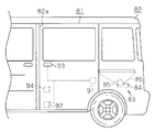
- the slide door 81 of the vehicle is supported movably in the front-rear direction with respect to the vehicle body 82.
- the slide door 81 opens and closes a door opening 82 a formed in the side portion of the vehicle body 82 by moving in the front-rear direction by a driving force of a drive member 83 mounted on the vehicle body 82 or a manual operation force. That is, the slide door 81 moves in a range from the fully closed position closing the door opening 82a to the fully open position opening the door opening 82a to the maximum.
- the driving member 83 includes a motor 84 capable of rotating in the forward and reverse directions, and a drum 85 rotationally driven by the motor 84. On the drum 85, a power transmission cable 86 whose both ends are connected to the slide door 81 is wound. The drive member 83 drives the slide door 81 by winding and unwinding the cable 86 in accordance with the rotation direction of the motor 84.
- the power transmission path between the motor 84 and the drum 85 is provided with an electromagnetic clutch capable of connecting and disconnecting the power transmission path.
- the electromagnetic clutch is switched to the connected state when the slide door 81 is electrically opened and closed, and transmits the rotation of the motor 84 to the drum 85.
- the electromagnetic clutch is switched to the disconnected state at the time of the manual opening and closing operation of the slide door 81, and disables the transmission of the rotation of the drum 85 to the motor 84. This is in order to separate the rotational torque of the drum 85 from the motor 84 and enable the open / close operation of the slide door 81 with a slight operating force, particularly when the slide door 81 is manually opened / closed.
- a fully closed lock 91 for holding the slide door 81 in the fully closed position by engaging with the vehicle body 82, and for the slide door 81 similarly held by engaging with the vehicle body 82
- a fully open lock 92 are installed inside the slide door 81.
- the fully open lock 92 releases the engagement with the vehicle body 82 by transmitting a manual operation force from the operation handle 93 or an electric operation force from the release actuator 94, and the slide door 81 can be closed.
- An object of the present invention is to provide a door opening and closing apparatus for a vehicle capable of suppressing an increase in the number of parts and an increase in the mass of the vehicle door.
- a drive member comprising a permanent magnet motor having two terminals and an output member rotationally driven by the permanent magnet motor, the drive member being a vehicle
- the vehicle door is installed on one of the body and the vehicle door and connected to the other of the vehicle body and the vehicle door through the output member, whereby the vehicle door is rotated with the rotation of the output member.
- the drive member, which is opened and closed, and the permanent magnet motor are selectively switched between an energized state in which power can be supplied through the two terminals and a brake state in which the terminals are short-circuited.
- a switching device configured to switch the permanent magnet motor to the braking state when the vehicle door is in the operating position excluding the fully closed position;
- Serial comprises a switching device, a vehicle door opening and closing device is provided.
- the permanent magnet motor when power is supplied to the permanent magnet motor through the two terminals in the conductive state, the permanent magnet motor is driven. Then, the output member is rotated in one direction, the vehicle door is opened accordingly, or the output member is rotated in the reverse direction, and the vehicle door is closed accordingly.
- the permanent magnet motor when the permanent magnet motor is switched to the brake state in which the terminals are short-circuited, the permanent magnet motor can generate a large cogging torque. By utilizing this cogging torque as a brake of the permanent magnet motor (and the output member), the vehicle door can be held at an operating position excluding the fully closed position even if it is a slope, for example.
- the vehicle door at the operating position excluding the fully closed position is eliminated by eliminating the state where the permanent magnet motor can generate a large cogging torque. You can release the As described above, since the vehicle door can be held and released by switching of the electric circuit by the switching device, the configuration of the entire device can be further simplified. Then, it is possible to suppress an increase in the number of parts and an increase in the mass of the vehicle door.
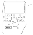
- FIG. 2 is a schematic view of the vehicle door opening and closing device of FIG. 1;
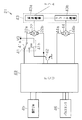
- FIG. 2 is a circuit diagram showing an electrical configuration of the vehicle door opening and closing device of FIG. 1;
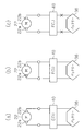
- (A)-(c) is the schematic which shows operation
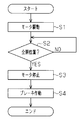
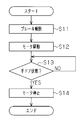
- the flowchart which shows the control procedure at the time of opening operation of the door opening / closing apparatus for vehicles of FIG.
- FIG. 7 is a schematic view showing a modified embodiment of the vehicle door opening and closing device of FIG. 1;
- front-rear direction means the front-rear direction of the vehicle.
- the upper rail 11 and the lower rail 12 are installed on the vehicle body 10 along the upper edge and the lower edge of the door opening 10a formed on the side portion thereof.
- the vehicle body 10 is provided with a quarter panel 10b positioned behind the door opening 10a, and a center rail 13 extending in the front-rear direction is installed on the quarter panel 10b.
- a slide door 20 as a vehicle door is supported by the upper rail 11, the lower rail 12 and the center rail 13 via a guide roller unit 14 so as to be movable in the front-rear direction.
- the slide door 20 opens and closes the door opening 10a in accordance with the movement in the front-rear direction.
- a cable guide 15 is installed in the quarter panel 10 b, and the cable guide 15 extends along the lower edge of the center rail 13 over the entire length of the center rail 13.
- a drive member 21 is fixed so as to be positioned at substantially the same height as the center rail 13.
- the drive member 21 has a drive motor 22 composed of a permanent magnet motor and a drum 23 as an output member rotationally driven by the drive motor 22.
- a first cable 24 and a second cable 25 are wound around the drum 23.
- Each of the first and second cables 24 and 25 is wound around the drum 23 in a state where the first end is locked to the drum 23 respectively.
- the first and second cables 24 and 25 are selectively wound and fed out to the drum 23 as the drive member 21 is driven.
- the drive member 21 further comprises an intermediate pulley 26.
- Each of the first and second cables 24 and 25 is passed from the slide door 20 to the vehicle body 10 through the intermediate pulley 26 and a guide pulley 27 connected to a guide roller unit 14 for moving the center rail 13. , Extends in the front-rear direction along the cable guide 15.
- the intermediate pulleys 26 and the guide pulleys 27 are disposed at the same height position as the center rail 13 and at a distance behind the drums 23, respectively.
- the first cable 24 is guided by the cable guide 15 and extends forward, and is connected to the vehicle body 10 at the front end of the cable guide 15 via a tensioner 28 connected to the second end of the first cable 24 ing.
- the second cable 25 is guided by the cable guide 15 and extends rearward, and the vehicle body at the rear end of the cable guide 15 via the tensioner 29 connected to the second end of the second cable 25 It is linked to ten.
- the slide door 20 moves rearward to open the door opening 10a.
- the slide door 20 moves forward to close the door opening 10a.
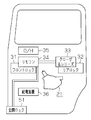
- a front lock 31 and a rear lock 32 that hold the slide door 20 in the fully closed position by being engaged with the vehicle body 10 are installed in the slide door 20.
- a close and release actuator 33 drivingly connected to the rear lock 32 is installed in the slide door 20, and the close and release actuator 33 closes the slide door 20 in a half door state to a fully closed position. , Function to release the holding of the slide door 20 in the fully closed position by the rear lock 32.
- the closer and release actuator 33 is mechanically linked with the front lock 31 via the remote controller 34, and releases the holding of the slide door 20 by the front lock 31 in the fully closed position.
- the front lock 31 and the rear lock 32 are mechanically linked with the operation handle 35 provided on the slide door 20, and the manual operation force is transmitted from the operation handle 35 as well. Release the hold in the fully closed position.
- the electric operation force (electric drive force) from the closer & release actuator 33 or the manual operation force from the operation handle 35 is front
- the front lock 31 and the rear lock 32 release the engagement between the slide door 20 and the vehicle body 10 to enable the slide door 20 to be opened.
- a power feeding device 36 for always feeding power to the closer and release actuator 33 together with the drive member 21 is mounted.
- an ECU (Electronic Control Unit) 40 related to the opening and closing control of the slide door 20 is mainly composed of, for example, a micro controller (MCU), and is provided in the drive member 21.
- the ECU 40 can be electrically connected to the first terminal 22 a of the drive motor 22 via the movable piece 41 a of the single-pole double-throw relay 41, for example, and the second terminal 22 b of the drive motor 22. Are connected electrically.
- the two terminals 22 a and 22 b of the drive motor 22 can be electrically connected via the movable piece 41 a of the relay 41, that is, can be short-circuited.
- the exciting coil 41 b of the relay 41 has a terminal connected to the positive electrode (VB) of the power supply device 36 and a terminal connected to the collector of the NPN transistor 42.
- the transistor 42 has a grounded emitter and a base connected to the ECU 40.
- the relay 41 and the transistor 42 constitute a switching device together with the ECU 40.
- the relay 41 electrically connects the ECU 40 and the first terminal 22 a of the drive motor 22 via the movable piece 41 a when the base of the transistor 42 is maintained in the non-energized state and the transistor 42 is in the off state.
- the drive motor 22 is made conductive.
- the ECU 40 drives the drive motor 22 by supplying a voltage from the power feeding device 36 to the drive motor 22 through the terminals 22a and 22b.
- the ECU 40 can switch the direction of the current supplied to the drive motor 22 so that the drive motor 22 can be rotated in a first direction or in a second direction opposite thereto depending on the direction of the current. . That is, at the time of non-switching control (at the time of non-energization) of the switching device (41, 42), the drive motor 22 is automatically brought into an energized state.
- the relay 41 shorts the two terminals 22a and 22b of the drive motor 22 via the exciting coil 41b. At this time, the drive motor 22 is electrically disconnected from the ECU 40 and is in a brake state in which a large cogging torque can be generated.
- the drive motor 22 is mechanically connected to the drum 23 via a speed reduction mechanism 43 a of a mechanism 43 incorporated in the drive member 21. Therefore, when the drive motor 22 is driven, the rotation of the drive motor 22 is decelerated by the reduction mechanism 43 a and transmitted to the drum 23.
- the reduction mechanism 43a of this embodiment is configured to be able to realize high-efficiency reduction, and for example, a staggered shaft gear mechanism including a pinion and a disk gear directly coupled to the rotation shaft of the drive motor 22, and a planet It consists of a combination with a gear mechanism. Such a configuration enables the drive motor 22 to be miniaturized. As described above, the slide door 20 is opened and closed as the drum 23 rotates.
- the ECU 40 is electrically connected to both terminals 44 a and 44 b of a clutch motor 44 which is, for example, a brush motor.
- the clutch motor 44 is drivingly connected to the clutch mechanism 43 b of the mechanism unit 43.
- the clutch mechanism 43b is mechanically linked with the reduction mechanism 43a, and the operating position is switched between the two positions by the clutch motor 44, whereby rotation transmission between the drive motor 22 and the drum 23 via the reduction mechanism 43a is performed. Selectively connected.
- connection / disconnection of rotation transmission between the drive motor 22 and the drum 23 by the clutch mechanism 43b is mechanical switching of the operating position of the clutch mechanism 43b by the clutch motor 44, even after the driving of the drive motor 22 is stopped. The switching state at that time is maintained. In other words, when receiving no force from the drive motor 22, the clutch mechanism 43b maintains the current switching state.
- the ECU 40 is electrically connected to the open / close operation switch 45, and detects the presence / absence of the open / close operation on the slide door 20 based on a signal from the open / close operation switch 45. Further, the ECU 40 is electrically connected to the pulse sensor 46, and detects the rotational position of the drive motor 22 or the like, that is, the operating position of the slide door 20 or the like based on the pulse signal from the pulse sensor 46. That is, an annular magnet rotated by the drive motor 22 is connected to the drive motor 22, and the polarity of the outer peripheral surface of the magnet is set between the N pole and the S pole at predetermined angles in the circumferential direction. It is supposed to be switched alternately.
- the pulse sensor 46 includes a pair of Hall elements disposed opposite to the outer peripheral surface of the magnet. Every time the magnet or drive motor 22 rotates a predetermined angle, these Hall elements output pulse signals having different phases. Therefore, the ECU 40 detects the rotational position of the drive motor 22 by counting, for example, the rising edges (or falling edges) of one of the pulse signals. Further, the ECU 40 detects the rotational speed of the drive motor 22 based on the time interval of the rising edge (or falling edge), and the rotational direction of the drive motor 22 (forward rotation based on the phase difference between both pulse signals). Or reverse).
- the first terminal 22a is connected to the ECU 40 by the relay 41 (see FIG. 3), and the drive motor 22 is in a state capable of conducting electricity.
- the ECU 40 rotates the drive motor 22 by supplying a voltage from the power feeding device 36 to the drive motor 22 through the terminals 22a and 22b.
- the drive motor 22 rotates in a first direction or an opposite second direction depending on the direction of the supplied current.
- the slide door 20 is opened or closed according to the rotation direction of the drive motor 22.
- both terminals 22a and 22b are shorted by the relay 41 (see FIG. 3), and the drive motor 22 is in the brake state.
- drive motor 22 is in a state capable of generating a large cogging torque.
- the ECU 40 holds the slide door 20 at the fully open position even if it is a slope, for example, by switching the drive motor 22 to the brake state when the slide door 20 is at the fully open position (an operating position other than the fully closed position). .
- the clutch mechanism 43b is switched to a state in which rotation transmission between the drive motor 22 and the drum 23 is enabled via the reduction mechanism 43a, the rotation transmission from the drum 23 to the drive motor 22 is accompanied by acceleration.
- the slide door 20 is held by the cooperation between the speed increase and the torque reduction corresponding to the speed increase ratio.
- the switching device (41, 42) is in a state in which the switching control can not be performed due to some failure, such as disconnection of the electrical connection between the power feeding device 36 and the ECU 40.
- the first terminal 22a is automatically connected to the ECU 40 so that the drive motor 22 can be energized. Therefore, even if the drive motor 22 is switched to the brake state at the fully open position of the slide door 20, for example, the drive motor 22 is automatically switched with the switching device (41, 42) falling into the control impossible state. Switch to the current enable state.
- the slide door 20 is completely operated with a relatively slight operation force. It can be closed to the closed position.
- the open / close operation switch 45 detects the open operation of the operation handle 35, and the close and release actuator 33 releases the holding of the slide door 20 at the fully closed position by the front lock 31 and the rear lock 32 and is activated. Be done. At this time, the drive motor 22 is switched to the conductive state.
- the ECU 40 drives the drive motor 22 to open the slide door 20 (step S1). Subsequently, the ECU 40 determines whether the slide door 20 has reached the fully open position (step S2), and continues driving the drive motor 22 until it reaches the fully open position. When the ECU 40 determines that the slide door 20 has reached the fully open position, the drive of the drive motor 22 is stopped (step S3). Subsequently, the ECU 40 switches the drive motor 22 to the brake state (step S4), and terminates the subsequent processing.
- the ECU 40 releases the drive motor 22 from the brake state and switches it to the energization enabled state (step S11). Then, the ECU 40 drives the drive motor 22 to close the slide door 20 (step S12). Subsequently, the ECU 40 determines whether the slide door 20 has reached the half door state (step S13), and continues driving the drive motor 22 until the half door state is reached. Then, when the ECU 40 determines that the slide door 20 has reached the half door state, the drive of the drive motor 22 is stopped (step S14), and the subsequent processing is ended.
- the half door state of the slide door 20 may be detected by a known latch switch (not shown) for detecting the state of the front lock 31 or the rear lock 32. If sufficient accuracy is ensured, a pulse is generated. It may be detected by the sensor 46.
- the closer and release actuator 33 is driven to hold the slide door 20 at the fully closed position by the front lock 31 and the rear lock 32. Accordingly, the slide door 20 that has reached the half-door state is pulled into the fully closed position by the closer and release actuator 33 and held in the fully closed position by the front lock 31 and the rear lock 32. It goes without saying that when the slide door 20 reaches the fully closed position, the drive motor 22 remains switched to the conductive state.
- this embodiment has the following advantages.
- the slide door 20 at the fully open position even on slopes. It can hold. Further, when the drive motor 22 is switched from the brake state to the conductive state, the state in which the drive motor 22 can generate a large cogging torque is cancelled, so that the holding of the slide door 20 at the fully open position can be released.
- the holding and releasing of the slide door 20 can be realized by switching of the electric circuit by the switching device (41, 42), the lock device (for example, fully open lock) and the release actuator as in the conventional example are adopted.
- the configuration of the entire device can be further simplified as compared to the case of And while being able to suppress the increase in the number of parts and cost, the mass increase of the slide door 20 can be suppressed.
- the rotational torque of the drum 23 can be The slide door 20 can be opened and closed with a slight operating force.
- the clutch mechanism 43 b enables rotation transmission between the drive motor 22 and the drum 23 in the brake state of the drive motor 22, the rotational torque of the drum 23 can be transmitted to the drive motor 22. Therefore, the increase in speed accompanied with the rotation transmission from the drum 23 to the drive motor 22 allows the slide door 20 to be held in cooperation with the increase in speed and a reduction in torque according to the increase ratio.
- the switching device (41, 42) maintains the energization enabled state of the drive motor 22 at the time of non-switching control (during non-energization). Therefore, for example, when the switching device (41, 42) falls into a state in which switching control can not be performed due to a failure or the like when the slide door 20 is held at the fully open position, large cogging torque generated in the drive motor 22 can be eliminated. Therefore, when the slide door 20 is manually closed in such a state, the slide door 20 can be closed with a relatively slight operation force.
- the mechanical clutch mechanism 43b that operates by receiving mechanical force, energization of the drive motor 22 by, for example, pinch detection etc. is performed during opening / closing operation of the slide door 20 electrically. Even if the opening and closing operation of the slide door 20 is stopped, the clutch mechanism 43b can be maintained in a state capable of transmitting the rotation between the drive motor 22 and the drum 23 via the reduction mechanism 43a. Therefore, the slide door 20 can be suitably opened and closed by resuming energization of the drive motor 22 by using the pulse sensor 46 in combination. In addition, the clutch mechanism 43b does not need to continue to be energized to maintain the connected state, for example, like an electromagnetic clutch, and the power consumption can be reduced.
- a fully open lock 51 may be installed in the slide door 20 to hold the slide door 20 in the fully open position by engaging with the vehicle body 10.
- the fully open lock 51 is mechanically linked to the closer and release actuator 33 via the remote controller 34, and the electrically close operating force is transmitted from the close and release actuator 33 to fully open the slide door 20. Release the hold on Further, the fully open lock 51 is mechanically linked with the operation handle 35, and the holding of the slide door 20 in the fully open position is released even when a manual operation force is transmitted from the operation handle 35.
- the fully open lock 51 releases the engagement with the vehicle body 10 to allow the slide door 20 to close.
- the slide door 20 can be held at the operation position. Therefore, as compared with the case where a lock device for holding the slide door 20 at any or predetermined operating position between the two positions except the fully closed position and the fully open position of the slide door 20 and a release actuator for releasing the same is employed.
- the configuration of the entire device can be further simplified.
- the fully open lock 51 and the front lock 31 mechanically connect with the closer & release actuator 33 without the remote controller 34. It may be linked to In this case, the inside handle or the outside handle and the close and release actuator 33 are electrically linked.
- the drive motor 22 may be switched to the brake state at any operation position or predetermined operation position except the fully closed position of the slide door 20, and the slide door 20 may be held at the operation position. .
- the fully open position or the fully closed position of the slide door 20 may be detected by an appropriate limiter switch, or may be detected by the pulse sensor 46 if sufficient accuracy is ensured.
- the reduction mechanism 43a may be omitted to directly connect the rotary shaft of the drive motor 22 and the drum 23.
- the speed reduction mechanism 43a may be a worm gear having low speed reduction efficiency. However, in this case, it is more preferable to provide a clutch in order to facilitate the manual opening and closing operation of the slide door 20.
- connection and disconnection of the rotation transmission between the drive motor 22 and the drum 23 may be performed by an electromagnetic clutch instead of the clutch mechanism 43b.
- the clutch mechanism 43b may be omitted, and the drive motor 22 and the drum 23 may be constantly connected so as to transmit rotation.
- a mechanical check mechanism may be further provided to hold the slide door 20 in the fully closed position in cooperation with the drive motor 22.
- the check mechanism may also be used as a cover for preventing the lower roller in the guide roller unit 14 from falling off.
- the polarity of the power feeding device 36 connected to the exciting coil 41 b may be reversed, and the transistor 42 may be of PNP type in accordance with this. Also, the transistor 42 may be an FET or the like.
- the circuit configuration of the switching device is an example.
- the ECU 40 has the ability to drive the relay 41 (excitation coil 41 b) directly, the transistor 42 may be omitted.
- a combination of semiconductor switches bipolar transistors, FETs, etc. may be used.
- the switching device may be changed to maintain the brake state of the drive motor 22 during non-switching control (during non-energization).
- SYMBOLS 10 Vehicle body, 20 ... Sliding door (vehicle door) 21, 21 ... Drive member, 22 ... Drive motor (permanent magnet motor), 22a, 22b ... Terminal, 23 ... Drum (output member) 40: ECU (switching device) 41 ... relay (switching device), 42 ... transistor (switching device), 43 ... mechanism portion, 43 a ... deceleration mechanism, 43 b ... clutch mechanism (clutch).
Landscapes
- Power-Operated Mechanisms For Wings (AREA)
- Engineering & Computer Science (AREA)
- Mechanical Engineering (AREA)
Abstract
Description
Claims (6)
- 2つの端子を備える永久磁石モータ及び該永久磁石モータにより回転駆動される出力部材を有する駆動部材であって、該駆動部材は車両ボディ及び車両ドアのうちの一方に設置されるとともに該出力部材を介して前記車両ボディ及び前記車両ドアの他方に連結されるように構成され、それによって前記出力部材の回転に伴い前記車両ドアが開閉作動する、前記駆動部材と、
前記永久磁石モータを、前記2つの端子を通じて電力の供給を受けることが可能な通電可能状態と、前記両端子間が短絡されるブレーキ状態とに選択的に切り替えるように構成された切替装置であって、前記車両ドアが全閉位置を除く作動位置にあるときに前記永久磁石モータを前記ブレーキ状態に切り替える、前記切替装置と、
を備える、車両用ドア開閉装置。 - 前記永久磁石モータと前記出力部材との間に設けられ、前記永久磁石モータと前記出力部材との間の回転伝達を断接するクラッチを備える、請求項1に記載の車両用ドア開閉装置。
- 前記クラッチは、機械的な力を受けて作動する機械式のクラッチである、請求項2に記載の車両用ドア開閉装置。
- 前記前記永久磁石モータと前記出力部材との間に設けられ、前記永久磁石モータの回転を減速して前記出力部材に伝達する減速機構を備える、請求項1~3の何れか一項に記載の車両用ドア開閉装置。
- 前記切替装置は、通電されたときに前記永久磁石モータを前記ブレーキ状態に切り替える一方、非通電時に前記永久磁石モータを前記通電可能状態に維持するように構成される、請求項1~4の何れか一項に記載の車車両用ドア開閉装置。
- 前記切替装置は、切替制御不能な状態に陥った場合に前記永久磁石モータを前記通電可能状態に維持するように構成される、請求項1~4の何れか一項に記載の車車両用ドア開閉装置。
Priority Applications (2)
| Application Number | Priority Date | Filing Date | Title |
|---|---|---|---|
| CN201290000911.9U CN203905706U (zh) | 2011-10-25 | 2012-09-13 | 车辆用门开闭装置 |
| US14/351,896 US9260901B2 (en) | 2011-10-25 | 2012-09-13 | Door-opening/closing device for use in vehicle |
Applications Claiming Priority (2)
| Application Number | Priority Date | Filing Date | Title |
|---|---|---|---|
| JP2011-234065 | 2011-10-25 | ||
| JP2011234065A JP5578154B2 (ja) | 2011-10-25 | 2011-10-25 | 車両用ドア開閉装置 |
Publications (1)
| Publication Number | Publication Date |
|---|---|
| WO2013061706A1 true WO2013061706A1 (ja) | 2013-05-02 |
Family
ID=48167544
Family Applications (1)
| Application Number | Title | Priority Date | Filing Date |
|---|---|---|---|
| PCT/JP2012/073420 Ceased WO2013061706A1 (ja) | 2011-10-25 | 2012-09-13 | 車両用ドア開閉装置 |
Country Status (4)
| Country | Link |
|---|---|
| US (1) | US9260901B2 (ja) |
| JP (1) | JP5578154B2 (ja) |
| CN (1) | CN203905706U (ja) |
| WO (1) | WO2013061706A1 (ja) |
Cited By (1)
| Publication number | Priority date | Publication date | Assignee | Title |
|---|---|---|---|---|
| CN105473802A (zh) * | 2013-08-30 | 2016-04-06 | 爱信精机株式会社 | 车辆用开闭体控制装置及车辆用开闭系统 |
Families Citing this family (30)
| Publication number | Priority date | Publication date | Assignee | Title |
|---|---|---|---|---|
| US9260882B2 (en) | 2009-03-12 | 2016-02-16 | Ford Global Technologies, Llc | Universal global latch system |
| US9551166B2 (en) | 2011-11-02 | 2017-01-24 | Ford Global Technologies, Llc | Electronic interior door release system |
| US9416565B2 (en) | 2013-11-21 | 2016-08-16 | Ford Global Technologies, Llc | Piezo based energy harvesting for e-latch systems |
| JP6204207B2 (ja) * | 2014-01-27 | 2017-09-27 | 株式会社ミツバ | 車両用開閉体の制御装置 |
| JP5796238B2 (ja) * | 2014-02-07 | 2015-10-21 | 三井金属アクト株式会社 | 車両用ドアの開閉装置 |
| US10323442B2 (en) | 2014-05-13 | 2019-06-18 | Ford Global Technologies, Llc | Electronic safe door unlatching operations |
| US10119308B2 (en) | 2014-05-13 | 2018-11-06 | Ford Global Technologies, Llc | Powered latch system for vehicle doors and control system therefor |
| US10273725B2 (en) | 2014-05-13 | 2019-04-30 | Ford Global Technologies, Llc | Customer coaching method for location of E-latch backup handles |
| US9903142B2 (en) | 2014-05-13 | 2018-02-27 | Ford Global Technologies, Llc | Vehicle door handle and powered latch system |
| US9909344B2 (en) | 2014-08-26 | 2018-03-06 | Ford Global Technologies, Llc | Keyless vehicle door latch system with powered backup unlock feature |
| US9694978B2 (en) | 2015-07-16 | 2017-07-04 | Goodrich Corporation | Cargo handling system |
| JP6586806B2 (ja) * | 2015-07-23 | 2019-10-09 | アイシン精機株式会社 | 車両用開閉体制御装置 |
| DE102015215631A1 (de) | 2015-08-17 | 2017-02-23 | Brose Fahrzeugteile Gmbh & Co. Kommanditgesellschaft, Bamberg | Vorrichtung zum manuellen und/oder elektromotorischen Verstellen oder Feststellen eines ersten Fahrzeugteils und eines zweiten Fahrzeugteils relativ zueinander |
| DE102015215627A1 (de) * | 2015-08-17 | 2017-02-23 | Brose Fahrzeugteile Gmbh & Co. Kommanditgesellschaft, Bamberg | Vorrichtung zum manuellen und/oder elektromotorischen Verstellen oder Feststellen eines ersten Fahrzeugteils und eines zweiten Fahrzeugteils relativ zueinander |
| DE102015215630A1 (de) | 2015-08-17 | 2017-02-23 | Brose Fahrzeugteile Gmbh & Co. Kommanditgesellschaft, Bamberg | Vorrichtung zum manuellen und/oder elektromotorischen Verstellen oder Feststellen eines ersten Fahrzeugteils und eines zweiten Fahrzeugteils relativ zueinander |
| US9725069B2 (en) | 2015-10-12 | 2017-08-08 | Ford Global Technologies, Llc | Keyless vehicle systems |
| CN105823450A (zh) * | 2016-04-29 | 2016-08-03 | 芜湖莫森泰克汽车科技股份有限公司 | 汽车滑门检测性能装置 |
| US10227810B2 (en) | 2016-08-03 | 2019-03-12 | Ford Global Technologies, Llc | Priority driven power side door open/close operations |
| US10087671B2 (en) | 2016-08-04 | 2018-10-02 | Ford Global Technologies, Llc | Powered driven door presenter for vehicle doors |
| US10329823B2 (en) | 2016-08-24 | 2019-06-25 | Ford Global Technologies, Llc | Anti-pinch control system for powered vehicle doors |
| US10458171B2 (en) * | 2016-09-19 | 2019-10-29 | Ford Global Technologies, Llc | Anti-pinch logic for door opening actuator |
| KR101795550B1 (ko) * | 2016-10-10 | 2017-11-10 | 현대자동차주식회사 | 슬라이딩 도어의 락킹 장치 |
| JP6915331B2 (ja) * | 2017-03-22 | 2021-08-04 | 株式会社アイシン | 車両用開閉体制御装置 |
| US10604970B2 (en) | 2017-05-04 | 2020-03-31 | Ford Global Technologies, Llc | Method to detect end-of-life in latches |
| WO2019055299A1 (en) * | 2017-09-13 | 2019-03-21 | Multimatic Patentco Llc | ELECTRIC DRIVE MODULE FOR VEHICLE DOOR |
| JP6939447B2 (ja) * | 2017-11-10 | 2021-09-22 | 株式会社アイシン | 車両用開閉体制御装置 |
| CN108111152B (zh) * | 2018-02-23 | 2023-10-13 | 安徽安凯汽车股份有限公司 | 一种客车乘客门测试用自动开关电路 |
| US10907386B2 (en) | 2018-06-07 | 2021-02-02 | Ford Global Technologies, Llc | Side door pushbutton releases |
| DE102019218172A1 (de) * | 2019-11-25 | 2021-05-27 | Vitesco Technologies GmbH | Aktuator für eine Seitentür eines Kraftfahrzeuges mit Haltefunktion |
| KR102463882B1 (ko) * | 2021-01-11 | 2022-11-07 | 주식회사 광진 | 자동차용 측면도어의 개폐장치 |
Citations (1)
| Publication number | Priority date | Publication date | Assignee | Title |
|---|---|---|---|---|
| JPH0613357Y2 (ja) * | 1986-03-26 | 1994-04-06 | 株式会社大井製作所 | 自動車用スライドドアの開閉装置 |
Family Cites Families (12)
| Publication number | Priority date | Publication date | Assignee | Title |
|---|---|---|---|---|
| DE3442894A1 (de) * | 1984-11-24 | 1986-05-28 | SWF Auto-Electric GmbH, 7120 Bietigheim-Bissingen | Stelleinrichtung, insbesondere zum verriegeln und entriegeln von kraftfahrzeugtueren |
| US4727679A (en) * | 1987-04-02 | 1988-03-01 | The Stanley Works | Swing-door operator system |
| US6148967A (en) * | 1998-07-10 | 2000-11-21 | Alliedsignal Inc. | Non-contacting and torquer brake mechanism |
| US6425205B2 (en) * | 2000-03-29 | 2002-07-30 | Delphi Technologies, Inc. | Vehicle liftgate power operating system |
| DE10117933A1 (de) * | 2001-04-10 | 2002-10-17 | Valeo Sicherheitssysteme Gmbh | Kraftfahrzeug mit einer automatisch betätigbaren Fahrzeugtür |
| TWI251645B (en) * | 2004-03-02 | 2006-03-21 | Ind Tech Res Inst | Reluctance brake device |
| US7780221B2 (en) * | 2006-04-06 | 2010-08-24 | Asmo Co., Ltd. | Clutch, motor device, and vehicle door opening and closing apparatus |
| JP4724853B2 (ja) | 2008-06-04 | 2011-07-13 | 三井金属アクト株式会社 | 車両用ドア開閉操作装置 |
| US8067909B2 (en) * | 2009-05-29 | 2011-11-29 | GM Global Technology Operations LLC | Method and apparatus for electromagnetically braking a motor |
| DE102009041498A1 (de) * | 2009-09-14 | 2011-03-24 | Brose Fahrzeugteile Gmbh & Co. Kommanditgesellschaft, Coburg | Feststellvorrichtung zum Arretieren eines Kraftfahrzeugteiles |
| WO2012039313A1 (ja) | 2010-09-24 | 2012-03-29 | アイシン精機 株式会社 | 車両用ドア駆動装置 |
| JP5569342B2 (ja) | 2010-11-04 | 2014-08-13 | アイシン精機株式会社 | 車両用ドア駆動装置 |
-
2011
- 2011-10-25 JP JP2011234065A patent/JP5578154B2/ja not_active Expired - Fee Related
-
2012
- 2012-09-13 CN CN201290000911.9U patent/CN203905706U/zh not_active Expired - Fee Related
- 2012-09-13 WO PCT/JP2012/073420 patent/WO2013061706A1/ja not_active Ceased
- 2012-09-13 US US14/351,896 patent/US9260901B2/en not_active Expired - Fee Related
Patent Citations (1)
| Publication number | Priority date | Publication date | Assignee | Title |
|---|---|---|---|---|
| JPH0613357Y2 (ja) * | 1986-03-26 | 1994-04-06 | 株式会社大井製作所 | 自動車用スライドドアの開閉装置 |
Cited By (3)
| Publication number | Priority date | Publication date | Assignee | Title |
|---|---|---|---|---|
| CN105473802A (zh) * | 2013-08-30 | 2016-04-06 | 爱信精机株式会社 | 车辆用开闭体控制装置及车辆用开闭系统 |
| US9790727B2 (en) | 2013-08-30 | 2017-10-17 | Aisin Seiki Kabushiki Kaisha | Vehicle opening/closing body control device and opening/closing system for vehicle |
| CN105473802B (zh) * | 2013-08-30 | 2017-11-10 | 爱信精机株式会社 | 车辆用开闭体控制装置及车辆用开闭系统 |
Also Published As
| Publication number | Publication date |
|---|---|
| JP2013091962A (ja) | 2013-05-16 |
| US9260901B2 (en) | 2016-02-16 |
| JP5578154B2 (ja) | 2014-08-27 |
| US20140245666A1 (en) | 2014-09-04 |
| CN203905706U (zh) | 2014-10-29 |
Similar Documents
| Publication | Publication Date | Title |
|---|---|---|
| JP5578154B2 (ja) | 車両用ドア開閉装置 | |
| US6405485B1 (en) | Door control equipment | |
| JP2013091962A5 (ja) | ||
| JP2018535881A (ja) | 磁気制動ユニットを備える、車両部品調節用の駆動装置 | |
| JP5040041B2 (ja) | 車両用ドアの開閉制御装置 | |
| KR100719144B1 (ko) | 구동장치 및 도어클로저 | |
| CN101087089B (zh) | 车辆自动开关装置 | |
| US7828132B2 (en) | Dual function holding device operable under a system power loss condition | |
| CN105934872A (zh) | 马达单元、带减速机构的马达以及滑动门自动开闭装置 | |
| JP2002327576A (ja) | 車両用ドア開閉駆動装置 | |
| CN101861442A (zh) | 用于上下车装置的驱动设备 | |
| US7607963B2 (en) | Control apparatus for opening/closing vehicle door | |
| US10174541B2 (en) | Control apparatus for opening and closing unit for vehicle | |
| JP2010090569A (ja) | モータ制御回路およびパワーウィンドウ装置 | |
| US7554234B2 (en) | Motor with rotation suppression mechanism for movable body | |
| US7946195B2 (en) | Steering apparatus for vehicle | |
| JP2008005656A (ja) | 車両用自動開閉装置 | |
| JP5266897B2 (ja) | 跳ね上げ式門扉 | |
| JP5759739B2 (ja) | 車両用ドア開閉装置の制御装置 | |
| JP2009275407A (ja) | ドアロック装置 | |
| JP5700663B2 (ja) | 車両用ドア開閉装置の制御装置、その制御方法及び車両用ドア開閉装置 | |
| JP4906423B2 (ja) | 車両用自動開閉装置 | |
| JP4221143B2 (ja) | 車両用開閉体の自動開閉装置 | |
| JP6915416B2 (ja) | 開閉体制御装置 | |
| JP2002369460A (ja) | 永久磁石型直流モータおよびモータ駆動型変速機操作装置 |
Legal Events
| Date | Code | Title | Description |
|---|---|---|---|
| WWE | Wipo information: entry into national phase |
Ref document number: 201290000911.9 Country of ref document: CN |
|
| 121 | Ep: the epo has been informed by wipo that ep was designated in this application |
Ref document number: 12843061 Country of ref document: EP Kind code of ref document: A1 |
|
| WWE | Wipo information: entry into national phase |
Ref document number: 14351896 Country of ref document: US |
|
| NENP | Non-entry into the national phase |
Ref country code: DE |
|
| WWE | Wipo information: entry into national phase |
Ref document number: IDP00201402956 Country of ref document: ID |
|
| 122 | Ep: pct application non-entry in european phase |
Ref document number: 12843061 Country of ref document: EP Kind code of ref document: A1 |