WO2013051406A1 - 充電装置 - Google Patents
充電装置 Download PDFInfo
- Publication number
- WO2013051406A1 WO2013051406A1 PCT/JP2012/074257 JP2012074257W WO2013051406A1 WO 2013051406 A1 WO2013051406 A1 WO 2013051406A1 JP 2012074257 W JP2012074257 W JP 2012074257W WO 2013051406 A1 WO2013051406 A1 WO 2013051406A1
- Authority
- WO
- WIPO (PCT)
- Prior art keywords
- charging
- time
- vehicle
- battery
- use interval
- Prior art date
Links
Images
Classifications
-
- B—PERFORMING OPERATIONS; TRANSPORTING
- B60—VEHICLES IN GENERAL
- B60L—PROPULSION OF ELECTRICALLY-PROPELLED VEHICLES; SUPPLYING ELECTRIC POWER FOR AUXILIARY EQUIPMENT OF ELECTRICALLY-PROPELLED VEHICLES; ELECTRODYNAMIC BRAKE SYSTEMS FOR VEHICLES IN GENERAL; MAGNETIC SUSPENSION OR LEVITATION FOR VEHICLES; MONITORING OPERATING VARIABLES OF ELECTRICALLY-PROPELLED VEHICLES; ELECTRIC SAFETY DEVICES FOR ELECTRICALLY-PROPELLED VEHICLES
- B60L53/00—Methods of charging batteries, specially adapted for electric vehicles; Charging stations or on-board charging equipment therefor; Exchange of energy storage elements in electric vehicles
- B60L53/10—Methods of charging batteries, specially adapted for electric vehicles; Charging stations or on-board charging equipment therefor; Exchange of energy storage elements in electric vehicles characterised by the energy transfer between the charging station and the vehicle
- B60L53/14—Conductive energy transfer
-
- B—PERFORMING OPERATIONS; TRANSPORTING
- B60—VEHICLES IN GENERAL
- B60L—PROPULSION OF ELECTRICALLY-PROPELLED VEHICLES; SUPPLYING ELECTRIC POWER FOR AUXILIARY EQUIPMENT OF ELECTRICALLY-PROPELLED VEHICLES; ELECTRODYNAMIC BRAKE SYSTEMS FOR VEHICLES IN GENERAL; MAGNETIC SUSPENSION OR LEVITATION FOR VEHICLES; MONITORING OPERATING VARIABLES OF ELECTRICALLY-PROPELLED VEHICLES; ELECTRIC SAFETY DEVICES FOR ELECTRICALLY-PROPELLED VEHICLES
- B60L50/00—Electric propulsion with power supplied within the vehicle
- B60L50/50—Electric propulsion with power supplied within the vehicle using propulsion power supplied by batteries or fuel cells
- B60L50/60—Electric propulsion with power supplied within the vehicle using propulsion power supplied by batteries or fuel cells using power supplied by batteries
-
- B—PERFORMING OPERATIONS; TRANSPORTING
- B60—VEHICLES IN GENERAL
- B60L—PROPULSION OF ELECTRICALLY-PROPELLED VEHICLES; SUPPLYING ELECTRIC POWER FOR AUXILIARY EQUIPMENT OF ELECTRICALLY-PROPELLED VEHICLES; ELECTRODYNAMIC BRAKE SYSTEMS FOR VEHICLES IN GENERAL; MAGNETIC SUSPENSION OR LEVITATION FOR VEHICLES; MONITORING OPERATING VARIABLES OF ELECTRICALLY-PROPELLED VEHICLES; ELECTRIC SAFETY DEVICES FOR ELECTRICALLY-PROPELLED VEHICLES
- B60L53/00—Methods of charging batteries, specially adapted for electric vehicles; Charging stations or on-board charging equipment therefor; Exchange of energy storage elements in electric vehicles
- B60L53/10—Methods of charging batteries, specially adapted for electric vehicles; Charging stations or on-board charging equipment therefor; Exchange of energy storage elements in electric vehicles characterised by the energy transfer between the charging station and the vehicle
- B60L53/11—DC charging controlled by the charging station, e.g. mode 4
-
- B—PERFORMING OPERATIONS; TRANSPORTING
- B60—VEHICLES IN GENERAL
- B60L—PROPULSION OF ELECTRICALLY-PROPELLED VEHICLES; SUPPLYING ELECTRIC POWER FOR AUXILIARY EQUIPMENT OF ELECTRICALLY-PROPELLED VEHICLES; ELECTRODYNAMIC BRAKE SYSTEMS FOR VEHICLES IN GENERAL; MAGNETIC SUSPENSION OR LEVITATION FOR VEHICLES; MONITORING OPERATING VARIABLES OF ELECTRICALLY-PROPELLED VEHICLES; ELECTRIC SAFETY DEVICES FOR ELECTRICALLY-PROPELLED VEHICLES
- B60L53/00—Methods of charging batteries, specially adapted for electric vehicles; Charging stations or on-board charging equipment therefor; Exchange of energy storage elements in electric vehicles
- B60L53/10—Methods of charging batteries, specially adapted for electric vehicles; Charging stations or on-board charging equipment therefor; Exchange of energy storage elements in electric vehicles characterised by the energy transfer between the charging station and the vehicle
- B60L53/14—Conductive energy transfer
- B60L53/18—Cables specially adapted for charging electric vehicles
-
- B—PERFORMING OPERATIONS; TRANSPORTING
- B60—VEHICLES IN GENERAL
- B60L—PROPULSION OF ELECTRICALLY-PROPELLED VEHICLES; SUPPLYING ELECTRIC POWER FOR AUXILIARY EQUIPMENT OF ELECTRICALLY-PROPELLED VEHICLES; ELECTRODYNAMIC BRAKE SYSTEMS FOR VEHICLES IN GENERAL; MAGNETIC SUSPENSION OR LEVITATION FOR VEHICLES; MONITORING OPERATING VARIABLES OF ELECTRICALLY-PROPELLED VEHICLES; ELECTRIC SAFETY DEVICES FOR ELECTRICALLY-PROPELLED VEHICLES
- B60L53/00—Methods of charging batteries, specially adapted for electric vehicles; Charging stations or on-board charging equipment therefor; Exchange of energy storage elements in electric vehicles
- B60L53/30—Constructional details of charging stations
- B60L53/305—Communication interfaces
-
- B—PERFORMING OPERATIONS; TRANSPORTING
- B60—VEHICLES IN GENERAL
- B60L—PROPULSION OF ELECTRICALLY-PROPELLED VEHICLES; SUPPLYING ELECTRIC POWER FOR AUXILIARY EQUIPMENT OF ELECTRICALLY-PROPELLED VEHICLES; ELECTRODYNAMIC BRAKE SYSTEMS FOR VEHICLES IN GENERAL; MAGNETIC SUSPENSION OR LEVITATION FOR VEHICLES; MONITORING OPERATING VARIABLES OF ELECTRICALLY-PROPELLED VEHICLES; ELECTRIC SAFETY DEVICES FOR ELECTRICALLY-PROPELLED VEHICLES
- B60L53/00—Methods of charging batteries, specially adapted for electric vehicles; Charging stations or on-board charging equipment therefor; Exchange of energy storage elements in electric vehicles
- B60L53/30—Constructional details of charging stations
- B60L53/31—Charging columns specially adapted for electric vehicles
-
- H—ELECTRICITY
- H02—GENERATION; CONVERSION OR DISTRIBUTION OF ELECTRIC POWER
- H02J—CIRCUIT ARRANGEMENTS OR SYSTEMS FOR SUPPLYING OR DISTRIBUTING ELECTRIC POWER; SYSTEMS FOR STORING ELECTRIC ENERGY
- H02J5/00—Circuit arrangements for transfer of electric power between ac networks and dc networks
-
- H—ELECTRICITY
- H02—GENERATION; CONVERSION OR DISTRIBUTION OF ELECTRIC POWER
- H02J—CIRCUIT ARRANGEMENTS OR SYSTEMS FOR SUPPLYING OR DISTRIBUTING ELECTRIC POWER; SYSTEMS FOR STORING ELECTRIC ENERGY
- H02J7/00—Circuit arrangements for charging or depolarising batteries or for supplying loads from batteries
- H02J7/007—Regulation of charging or discharging current or voltage
- H02J7/0071—Regulation of charging or discharging current or voltage with a programmable schedule
-
- H—ELECTRICITY
- H02—GENERATION; CONVERSION OR DISTRIBUTION OF ELECTRIC POWER
- H02J—CIRCUIT ARRANGEMENTS OR SYSTEMS FOR SUPPLYING OR DISTRIBUTING ELECTRIC POWER; SYSTEMS FOR STORING ELECTRIC ENERGY
- H02J7/00—Circuit arrangements for charging or depolarising batteries or for supplying loads from batteries
- H02J7/02—Circuit arrangements for charging or depolarising batteries or for supplying loads from batteries for charging batteries from ac mains by converters
- H02J7/04—Regulation of charging current or voltage
-
- B—PERFORMING OPERATIONS; TRANSPORTING
- B60—VEHICLES IN GENERAL
- B60L—PROPULSION OF ELECTRICALLY-PROPELLED VEHICLES; SUPPLYING ELECTRIC POWER FOR AUXILIARY EQUIPMENT OF ELECTRICALLY-PROPELLED VEHICLES; ELECTRODYNAMIC BRAKE SYSTEMS FOR VEHICLES IN GENERAL; MAGNETIC SUSPENSION OR LEVITATION FOR VEHICLES; MONITORING OPERATING VARIABLES OF ELECTRICALLY-PROPELLED VEHICLES; ELECTRIC SAFETY DEVICES FOR ELECTRICALLY-PROPELLED VEHICLES
- B60L2200/00—Type of vehicles
- B60L2200/26—Rail vehicles
-
- B—PERFORMING OPERATIONS; TRANSPORTING
- B60—VEHICLES IN GENERAL
- B60L—PROPULSION OF ELECTRICALLY-PROPELLED VEHICLES; SUPPLYING ELECTRIC POWER FOR AUXILIARY EQUIPMENT OF ELECTRICALLY-PROPELLED VEHICLES; ELECTRODYNAMIC BRAKE SYSTEMS FOR VEHICLES IN GENERAL; MAGNETIC SUSPENSION OR LEVITATION FOR VEHICLES; MONITORING OPERATING VARIABLES OF ELECTRICALLY-PROPELLED VEHICLES; ELECTRIC SAFETY DEVICES FOR ELECTRICALLY-PROPELLED VEHICLES
- B60L2210/00—Converter types
- B60L2210/30—AC to DC converters
-
- B—PERFORMING OPERATIONS; TRANSPORTING
- B60—VEHICLES IN GENERAL
- B60L—PROPULSION OF ELECTRICALLY-PROPELLED VEHICLES; SUPPLYING ELECTRIC POWER FOR AUXILIARY EQUIPMENT OF ELECTRICALLY-PROPELLED VEHICLES; ELECTRODYNAMIC BRAKE SYSTEMS FOR VEHICLES IN GENERAL; MAGNETIC SUSPENSION OR LEVITATION FOR VEHICLES; MONITORING OPERATING VARIABLES OF ELECTRICALLY-PROPELLED VEHICLES; ELECTRIC SAFETY DEVICES FOR ELECTRICALLY-PROPELLED VEHICLES
- B60L2210/00—Converter types
- B60L2210/40—DC to AC converters
-
- B—PERFORMING OPERATIONS; TRANSPORTING
- B60—VEHICLES IN GENERAL
- B60L—PROPULSION OF ELECTRICALLY-PROPELLED VEHICLES; SUPPLYING ELECTRIC POWER FOR AUXILIARY EQUIPMENT OF ELECTRICALLY-PROPELLED VEHICLES; ELECTRODYNAMIC BRAKE SYSTEMS FOR VEHICLES IN GENERAL; MAGNETIC SUSPENSION OR LEVITATION FOR VEHICLES; MONITORING OPERATING VARIABLES OF ELECTRICALLY-PROPELLED VEHICLES; ELECTRIC SAFETY DEVICES FOR ELECTRICALLY-PROPELLED VEHICLES
- B60L2240/00—Control parameters of input or output; Target parameters
- B60L2240/10—Vehicle control parameters
- B60L2240/36—Temperature of vehicle components or parts
-
- B—PERFORMING OPERATIONS; TRANSPORTING
- B60—VEHICLES IN GENERAL
- B60L—PROPULSION OF ELECTRICALLY-PROPELLED VEHICLES; SUPPLYING ELECTRIC POWER FOR AUXILIARY EQUIPMENT OF ELECTRICALLY-PROPELLED VEHICLES; ELECTRODYNAMIC BRAKE SYSTEMS FOR VEHICLES IN GENERAL; MAGNETIC SUSPENSION OR LEVITATION FOR VEHICLES; MONITORING OPERATING VARIABLES OF ELECTRICALLY-PROPELLED VEHICLES; ELECTRIC SAFETY DEVICES FOR ELECTRICALLY-PROPELLED VEHICLES
- B60L2240/00—Control parameters of input or output; Target parameters
- B60L2240/60—Navigation input
- B60L2240/66—Ambient conditions
- B60L2240/662—Temperature
-
- B—PERFORMING OPERATIONS; TRANSPORTING
- B60—VEHICLES IN GENERAL
- B60L—PROPULSION OF ELECTRICALLY-PROPELLED VEHICLES; SUPPLYING ELECTRIC POWER FOR AUXILIARY EQUIPMENT OF ELECTRICALLY-PROPELLED VEHICLES; ELECTRODYNAMIC BRAKE SYSTEMS FOR VEHICLES IN GENERAL; MAGNETIC SUSPENSION OR LEVITATION FOR VEHICLES; MONITORING OPERATING VARIABLES OF ELECTRICALLY-PROPELLED VEHICLES; ELECTRIC SAFETY DEVICES FOR ELECTRICALLY-PROPELLED VEHICLES
- B60L2240/00—Control parameters of input or output; Target parameters
- B60L2240/80—Time limits
-
- B—PERFORMING OPERATIONS; TRANSPORTING
- B60—VEHICLES IN GENERAL
- B60L—PROPULSION OF ELECTRICALLY-PROPELLED VEHICLES; SUPPLYING ELECTRIC POWER FOR AUXILIARY EQUIPMENT OF ELECTRICALLY-PROPELLED VEHICLES; ELECTRODYNAMIC BRAKE SYSTEMS FOR VEHICLES IN GENERAL; MAGNETIC SUSPENSION OR LEVITATION FOR VEHICLES; MONITORING OPERATING VARIABLES OF ELECTRICALLY-PROPELLED VEHICLES; ELECTRIC SAFETY DEVICES FOR ELECTRICALLY-PROPELLED VEHICLES
- B60L2260/00—Operating Modes
- B60L2260/40—Control modes
- B60L2260/50—Control modes by future state prediction
- B60L2260/58—Departure time prediction
-
- H—ELECTRICITY
- H01—ELECTRIC ELEMENTS
- H01M—PROCESSES OR MEANS, e.g. BATTERIES, FOR THE DIRECT CONVERSION OF CHEMICAL ENERGY INTO ELECTRICAL ENERGY
- H01M10/00—Secondary cells; Manufacture thereof
- H01M10/42—Methods or arrangements for servicing or maintenance of secondary cells or secondary half-cells
- H01M10/44—Methods for charging or discharging
-
- H—ELECTRICITY
- H01—ELECTRIC ELEMENTS
- H01M—PROCESSES OR MEANS, e.g. BATTERIES, FOR THE DIRECT CONVERSION OF CHEMICAL ENERGY INTO ELECTRICAL ENERGY
- H01M2200/00—Safety devices for primary or secondary batteries
- H01M2200/20—Pressure-sensitive devices
-
- H—ELECTRICITY
- H02—GENERATION; CONVERSION OR DISTRIBUTION OF ELECTRIC POWER
- H02J—CIRCUIT ARRANGEMENTS OR SYSTEMS FOR SUPPLYING OR DISTRIBUTING ELECTRIC POWER; SYSTEMS FOR STORING ELECTRIC ENERGY
- H02J2310/00—The network for supplying or distributing electric power characterised by its spatial reach or by the load
- H02J2310/40—The network being an on-board power network, i.e. within a vehicle
- H02J2310/48—The network being an on-board power network, i.e. within a vehicle for electric vehicles [EV] or hybrid vehicles [HEV]
-
- H—ELECTRICITY
- H02—GENERATION; CONVERSION OR DISTRIBUTION OF ELECTRIC POWER
- H02J—CIRCUIT ARRANGEMENTS OR SYSTEMS FOR SUPPLYING OR DISTRIBUTING ELECTRIC POWER; SYSTEMS FOR STORING ELECTRIC ENERGY
- H02J7/00—Circuit arrangements for charging or depolarising batteries or for supplying loads from batteries
- H02J7/0013—Circuit arrangements for charging or depolarising batteries or for supplying loads from batteries acting upon several batteries simultaneously or sequentially
- H02J7/0014—Circuits for equalisation of charge between batteries
-
- Y—GENERAL TAGGING OF NEW TECHNOLOGICAL DEVELOPMENTS; GENERAL TAGGING OF CROSS-SECTIONAL TECHNOLOGIES SPANNING OVER SEVERAL SECTIONS OF THE IPC; TECHNICAL SUBJECTS COVERED BY FORMER USPC CROSS-REFERENCE ART COLLECTIONS [XRACs] AND DIGESTS
- Y02—TECHNOLOGIES OR APPLICATIONS FOR MITIGATION OR ADAPTATION AGAINST CLIMATE CHANGE
- Y02E—REDUCTION OF GREENHOUSE GAS [GHG] EMISSIONS, RELATED TO ENERGY GENERATION, TRANSMISSION OR DISTRIBUTION
- Y02E60/00—Enabling technologies; Technologies with a potential or indirect contribution to GHG emissions mitigation
- Y02E60/10—Energy storage using batteries
-
- Y—GENERAL TAGGING OF NEW TECHNOLOGICAL DEVELOPMENTS; GENERAL TAGGING OF CROSS-SECTIONAL TECHNOLOGIES SPANNING OVER SEVERAL SECTIONS OF THE IPC; TECHNICAL SUBJECTS COVERED BY FORMER USPC CROSS-REFERENCE ART COLLECTIONS [XRACs] AND DIGESTS
- Y02—TECHNOLOGIES OR APPLICATIONS FOR MITIGATION OR ADAPTATION AGAINST CLIMATE CHANGE
- Y02T—CLIMATE CHANGE MITIGATION TECHNOLOGIES RELATED TO TRANSPORTATION
- Y02T10/00—Road transport of goods or passengers
- Y02T10/60—Other road transportation technologies with climate change mitigation effect
- Y02T10/70—Energy storage systems for electromobility, e.g. batteries
-
- Y—GENERAL TAGGING OF NEW TECHNOLOGICAL DEVELOPMENTS; GENERAL TAGGING OF CROSS-SECTIONAL TECHNOLOGIES SPANNING OVER SEVERAL SECTIONS OF THE IPC; TECHNICAL SUBJECTS COVERED BY FORMER USPC CROSS-REFERENCE ART COLLECTIONS [XRACs] AND DIGESTS
- Y02—TECHNOLOGIES OR APPLICATIONS FOR MITIGATION OR ADAPTATION AGAINST CLIMATE CHANGE
- Y02T—CLIMATE CHANGE MITIGATION TECHNOLOGIES RELATED TO TRANSPORTATION
- Y02T10/00—Road transport of goods or passengers
- Y02T10/60—Other road transportation technologies with climate change mitigation effect
- Y02T10/7072—Electromobility specific charging systems or methods for batteries, ultracapacitors, supercapacitors or double-layer capacitors
-
- Y—GENERAL TAGGING OF NEW TECHNOLOGICAL DEVELOPMENTS; GENERAL TAGGING OF CROSS-SECTIONAL TECHNOLOGIES SPANNING OVER SEVERAL SECTIONS OF THE IPC; TECHNICAL SUBJECTS COVERED BY FORMER USPC CROSS-REFERENCE ART COLLECTIONS [XRACs] AND DIGESTS
- Y02—TECHNOLOGIES OR APPLICATIONS FOR MITIGATION OR ADAPTATION AGAINST CLIMATE CHANGE
- Y02T—CLIMATE CHANGE MITIGATION TECHNOLOGIES RELATED TO TRANSPORTATION
- Y02T10/00—Road transport of goods or passengers
- Y02T10/60—Other road transportation technologies with climate change mitigation effect
- Y02T10/72—Electric energy management in electromobility
-
- Y—GENERAL TAGGING OF NEW TECHNOLOGICAL DEVELOPMENTS; GENERAL TAGGING OF CROSS-SECTIONAL TECHNOLOGIES SPANNING OVER SEVERAL SECTIONS OF THE IPC; TECHNICAL SUBJECTS COVERED BY FORMER USPC CROSS-REFERENCE ART COLLECTIONS [XRACs] AND DIGESTS
- Y02—TECHNOLOGIES OR APPLICATIONS FOR MITIGATION OR ADAPTATION AGAINST CLIMATE CHANGE
- Y02T—CLIMATE CHANGE MITIGATION TECHNOLOGIES RELATED TO TRANSPORTATION
- Y02T90/00—Enabling technologies or technologies with a potential or indirect contribution to GHG emissions mitigation
- Y02T90/10—Technologies relating to charging of electric vehicles
- Y02T90/12—Electric charging stations
-
- Y—GENERAL TAGGING OF NEW TECHNOLOGICAL DEVELOPMENTS; GENERAL TAGGING OF CROSS-SECTIONAL TECHNOLOGIES SPANNING OVER SEVERAL SECTIONS OF THE IPC; TECHNICAL SUBJECTS COVERED BY FORMER USPC CROSS-REFERENCE ART COLLECTIONS [XRACs] AND DIGESTS
- Y02—TECHNOLOGIES OR APPLICATIONS FOR MITIGATION OR ADAPTATION AGAINST CLIMATE CHANGE
- Y02T—CLIMATE CHANGE MITIGATION TECHNOLOGIES RELATED TO TRANSPORTATION
- Y02T90/00—Enabling technologies or technologies with a potential or indirect contribution to GHG emissions mitigation
- Y02T90/10—Technologies relating to charging of electric vehicles
- Y02T90/14—Plug-in electric vehicles
-
- Y—GENERAL TAGGING OF NEW TECHNOLOGICAL DEVELOPMENTS; GENERAL TAGGING OF CROSS-SECTIONAL TECHNOLOGIES SPANNING OVER SEVERAL SECTIONS OF THE IPC; TECHNICAL SUBJECTS COVERED BY FORMER USPC CROSS-REFERENCE ART COLLECTIONS [XRACs] AND DIGESTS
- Y02—TECHNOLOGIES OR APPLICATIONS FOR MITIGATION OR ADAPTATION AGAINST CLIMATE CHANGE
- Y02T—CLIMATE CHANGE MITIGATION TECHNOLOGIES RELATED TO TRANSPORTATION
- Y02T90/00—Enabling technologies or technologies with a potential or indirect contribution to GHG emissions mitigation
- Y02T90/10—Technologies relating to charging of electric vehicles
- Y02T90/16—Information or communication technologies improving the operation of electric vehicles
Definitions
- the present invention relates to a charging device.
- a charging device for a vehicle that is installed in a parking lot and supplies electric power to a traveling battery of a vehicle that uses an electric motor as a driving force source for charging, and stores advertising data that is data for presenting an advertisement
- An advertisement data storage unit and an advertisement data transmission unit that transmits the advertisement data stored in the advertisement data storage unit to the vehicle, wherein transmission of the advertisement data from the advertisement data transmission unit to the vehicle is performed.
- a vehicle charging apparatus that charges a battery for traveling after completion and charges the battery for traveling until the battery is fully charged (Patent Document 1).
- the charging time is determined according to the free capacity of the traveling battery, and there are vehicles that are already charged by the vehicle charging device. Since charging cannot be started until the battery of the vehicle that has been charged first is fully charged, there is a problem that the charging waiting time becomes long.
- the problem to be solved by the present invention is to provide a charging device that can shorten the charging waiting time.
- the present invention includes a charging time setting means for setting a charging time for charging a battery, a charging end time of a first vehicle connected to a charger, and a charging start time of a second vehicle that charges after the first vehicle. And a use interval time calculating means for calculating a use interval time of the charger, which is a time between them, and the above problem is solved by setting the charge time according to the use interval time.
- the present invention can shorten the charging waiting time because the charging time is adjusted after determining whether or not there is a vehicle waiting for charging according to the length of the use interval time.
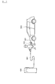
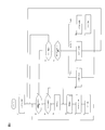
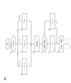
- FIG. 1 is a schematic diagram of a charging system including a charging device according to an embodiment of the present invention. It is a block diagram of the charging device of FIG. It is a flowchart which shows the control procedure of the charging device of FIG. It is a flowchart which shows the control procedure of the charge control of FIG.
- FIG. 1 is a schematic diagram of a charging system including a charging device according to an embodiment of the present invention.
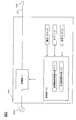
- FIG. 2 is a block diagram of the charging apparatus of this example.
- the charging system of this example is provided in a parking lot of a shopping mall, a parking lot of a facility that provides a car sharing service for electric vehicles, a parking lot of a company that uses an electric vehicle as a company car, etc. It is done.
- the charging system in the present example is provided with a charging device 100 for charging a traveling battery (not shown) of the vehicle 300.
- the vehicle 300 in the present embodiment is a vehicle having a motor generator as a power source and a battery such as a running battery that charges and discharges the motor generator, for example, an electric vehicle or a plug-in type hybrid car. Etc. can be illustrated.
- the operation panel 2 which is a touch panel is provided on the surface of the charging device 100.
- a charging operator for example, a driver or the like
- who performs a charging operation touches a button on the operation panel 2 according to the guidance displayed on the operation panel 2 when charging the battery of the vehicle 300 to start charging.
- operation for charge control such as completion
- the charging device 100 is a charging stand that charges the traveling battery of the vehicle 300 by supplying electric power to the vehicle 300.
- This charging device 100 has a built-in charger 1 including a power converter that converts AC power of a commercial AC power supply 200 into DC power and boosts the DC power to a predetermined voltage.
- the supplied direct current is supplied to the battery of the vehicle 300 via the charging cable 101.
- a charging connector 102 is attached to the tip of the charging cable 101, and the charging operator attaches the charging connector 102 to a power supply inlet 301 of the vehicle 300 so that the charging cable 101 is attached. Via, the charging device 100 and the battery of the vehicle 300 are electrically connected.
- the charging device 100 includes a charger 1, an operation panel 2, a timer 3, a temperature sensor 4, and a control unit 10.
- the charging device 100 is connected to an AC power source 200.
- a charging connector 102 is connected to the power output side of the charging apparatus 100 via a charging cable 101.
- the charger 1 has an inverter and the like, and is a charging circuit for charging the battery of the vehicle 300.
- Charger 1 is controlled based on a control signal from control unit 10, converts AC power supplied from AC power supply 200 into power suitable for charging a battery for traveling, and converts the power into vehicle 300.
- the battery is charged by supplying the battery.
- the operation panel 2 is a touch panel provided on the surface of the charging device 100 and displays a button for starting charging and a button for ending charging. When the power receiving operator touches the button, the operation panel 2 sends a signal corresponding to the button, for example, an operation signal for starting charging or an operation signal for ending charging to the control unit 10. Send.
- the timer 3 is a clock for measuring the usage interval of the charging device 100, and starts and stops based on a control signal from the control unit 10.
- the temperature sensor 4 is a sensor for detecting the environmental temperature (ambient temperature) of the environment where the charging apparatus 100 is set.
- the control unit 10 includes a use interval time calculation unit 11 and a charging time setting unit 12.
- the control unit 10 is a controller for controlling the charger 1, the operation panel 2, the timer 3, and the temperature sensor 4, and controls the entire charging device 100.
- the use interval time calculation unit 11 measures from the time information from the timer 3 the time between the charging end time of the previously charged vehicle and the charging start time of the vehicle charged immediately after the previously charged vehicle. By doing so, the use interval time of the charger 1 is calculated.
- the charging time setting unit 12 sets the charging time of the battery of the vehicle 300, in other words, the time during which power is supplied from the charger 1 to the battery. As will be described later, the charging time setting unit 12 sets the charging time according to the usage interval time calculated by the usage interval time calculation unit 11.
- the charging device 100 of this embodiment are determined maximum time charging time (T max) in advance, as a rule, once the power supply time per charge does not exceed the maximum charging time (T max) . Then, as will be described later, the charging device 100 charges the battery with the charging time set by the charging time setting unit 12, and when the charging time is reached from the time when the charging of the battery is started, or the charging capacity of the battery When the battery reaches full charge, the charging is terminated.
- control unit 10 controls charger 1 and is set by charging time setting unit 12. Charging starts at the specified charging time.
- the controller 10 monitors the capacity of the battery while the battery is being charged. And the control part 10 complete
- the control unit 10 ends the charging.
- the control unit 10 displays that the charging is terminated on the display of the charging device 100.
- control unit 10 calculates the usage interval time by the usage interval time calculation unit 11.
- the use interval time will be described.
- the vehicle 300 when the vehicle 300 is connected to the charging cable 101 and is being charged, the other vehicle 300 that wants to charge using the same charging device 100 finishes charging the vehicle 300 being charged. You have to wait until you do. If the vehicle 300 other than the other vehicle 300 is to be charged using the same charging device, the vehicle that has been charged first and the vehicle that has been waiting for the vehicle to be charged first are also charged. It is necessary to wait until the end.
- the first vehicle is charging, the second vehicle is waiting for charging, and the third vehicle is waiting for charging side by side after the second.
- the first vehicle parks in a predetermined parking space and charges it.
- the first vehicle moves the vehicle from the predetermined parking space and then waits for charging.
- the second vehicle moves the vehicle from the predetermined parking space, and then the third vehicle waiting for charging is parked in the predetermined parking space, Start charging.
- the use interval time of the charger 1 is the time from the charging end time of the first vehicle to the charging start time of the second vehicle, and from the charging end time of the second vehicle to the third vehicle. This is the time until the charging start time. That is, the use interval time is a time when the charging device 100 is not used, and corresponds to a time when no power is output from the charger 1.
- the use interval time calculation unit 12 uses the timer 3 to calculate the use interval time.
- the control unit 10 transmits an activation signal for starting the timer 3 to the timer 3 at the same timing as the completion of the charging. .
- the timer 3 is activated based on the activation signal and starts measuring the elapsed time ( Tn ) from the charging end time.
- the first vehicle that has finished charging moves the vehicle, the second vehicle is parked in a predetermined parking space, and the charging connector 102 is connected to the second vehicle.
- the charging operator of the second vehicle touches the button indicating the start of charging on the display screen of the operation panel 2, a signal indicating the start of charging is transmitted from the operation panel 2 to the control unit 10.
- the control unit 10 transmits a stop signal for stopping the timer 3 to the timer 3. The timer 3 is stopped based on the stop signal.
- the use interval time calculation unit 11 calculates the measurement time from the start to the end of the timer as the use interval time. Thereby, the use interval time calculation unit 11 calculates the use interval time, which is the time from the end of charging to the start of the next charging.
- the control unit 10 determines whether the charging device 100 has been recharged by the same vehicle or whether there is a vehicle traffic jam for charging according to the use interval time calculated by the use interval time calculation unit 11. Therefore, a recharge threshold time (T a ) and a vehicle congestion threshold time (T b ) are set.
- the recharge threshold time (T a ) is set to a time shorter than the vehicle congestion threshold time (T b ).
- the recharge threshold time (T a ) will be described. It is assumed that the vehicle 300 is charged by the charging device 100 and that the charging has ended because the elapsed time from the start of charging has reached the maximum charging time (T max ) before reaching the full charge of the battery of the vehicle 300. It is assumed that there is no vehicle waiting for charging by the charging device 100 other than the vehicle 300 at the end of charging. The charging operator of the vehicle 300 confirms that no vehicle is waiting for charging in order to fully charge the battery, operates the operation panel 2 again, and the charging start button is pressed to charge the vehicle. To resume.
- the recharge threshold time (T a ) is set based on the time required for recharging to be resumed with the same vehicle from the end of charging.
- the vehicle traffic jam threshold time (T b ) will be described.
- the first vehicle 300 is charged by the charging device 100, and charging has ended because the elapsed time from the start of charging has reached the maximum charging time (T max ) before the battery of the vehicle 300 reaches full charge. And Then, it is assumed that, other than the first vehicle 300, other vehicles are waiting for charging with the charging device 100 at the end of charging.
- the charging operator of the first vehicle 300 moves the first vehicle 300 from a predetermined parking space in order to switch charging to another vehicle 300 that is waiting for charging. Then, the second vehicle 300 waiting for charging is parked in a predetermined parking space, the charging operator of the second vehicle 300 operates the operation panel 2, the charging start button is pressed, and charging is performed. Be started.
- the vehicle traffic congestion threshold time (T b ) is set based on the time required to start charging with a different vehicle from the end of charging, and is set to be longer than the recharging threshold time (T a ).
- the vehicle traffic congestion threshold time (T b ) may be set according to the moving location of the vehicle including a predetermined parking space.
- the use interval time from the charging end time to the next charging start time is the recharging threshold time (T a ) and the vehicle congestion threshold. It becomes longer than the time (T b ).
- the control unit 10 compares the use interval time calculated by the use interval time calculation unit 11 with the recharge threshold time (T a ) and the vehicle congestion threshold time (T b ). When the use interval time is equal to or greater than the vehicle traffic jam threshold time (T b ), the control unit 10 determines that recharging by the same vehicle is not performed and that there is no vehicle traffic jam waiting for charging. Then, the flag indicating the usage status of the charging device is set to “0”. When the use interval time is longer than the recharge threshold time (T a ) and shorter than the vehicle congestion threshold time (T b ), the control unit 10 determines that the vehicle congestion for waiting for charging has occurred. The flag indicating the usage status of the charging device is set to “1”. When the use interval time is equal to or shorter than the recharge threshold time (T a ), the control unit 10 determines that recharge by the same vehicle has been performed, and sets a flag indicating the use status of the charging device to “2”. To do.
- a coefficient (ratio) for adjusting the charging time according to the state of the flag is set. Then, the charging time setting unit 12 sets the charging time by multiplying the maximum charging time (T max ) by a coefficient.
- T max maximum charging time
- the coefficient (R 0 ) when the flag is “0” is set to “1”.
- the coefficient (R 1 ) when the flag is “1” is set to a value smaller than “1”, for example, “0.8”.
- the coefficient (R 2 ) when the flag is “2” is set to a coefficient larger than the coefficient (R 1 ), for example, “0.9”.
- the charging time setting unit 12 sets the charging time according to the temperature detected by the temperature sensor 4. For example, when the temperature of the environment in which the charging apparatus 100 is set is low, such as in a midnight time zone in a cold region, the charging efficiency of the battery may be lower than in the daytime. And since the temperature sensor 4 has detected the external temperature of the charging device 100, the charging time setting part 12 sets the temperature coefficient ((alpha)) for adjusting charging time according to the detected temperature of the temperature sensor 4. The charging time is set by multiplying the maximum charging time (T max ) by the temperature coefficient ( ⁇ ). The temperature coefficient ( ⁇ ) is a value greater than 1.
- the controller 10 is preset with a threshold temperature for determining whether or not to change the charging time.
- the threshold temperature is a threshold set in advance based on the environment in which the charging apparatus 100 is set, the charging efficiency with respect to the environmental temperature, and the like. Then, the control unit 10 compares the detected temperature of the temperature sensor 4 with the threshold temperature. When the detected temperature is higher than the threshold temperature, the control unit 10 determines that the environmental temperature of the charging device 100 is high and it is not necessary to lengthen the charging time, and the charging time setting unit 12 sets the temperature coefficient ( ⁇ ). Control is performed so as not to multiply the maximum charging time (T max ).
- the control unit 10 determines that the environmental temperature of the charging device 100 is low and the charging time needs to be increased, and the charging time setting unit 12 determines the temperature coefficient ( ⁇ ) Is multiplied by the maximum charging time (T max ) to control to increase the charging time.
- the charging time setting unit 12 sets the temperature coefficient ( ⁇ ), A charging time longer than the maximum charging time (T max ) can be set.
- T max the maximum charging time
- FIG. 3 is a flowchart showing the control procedure of the charging apparatus of this example.
- FIG. 4 is a flowchart showing a control procedure of charge control in the control process shown in FIG.
- step S1 When the main switch of the charging device 100 of this example is turned on, in step S1, the control unit 10 sets a flag to “0” as an initial state. In step S ⁇ b> 2, based on the operation signal from operation panel 2, control unit 10 detects whether or not a charging start instruction has been issued by the charging operator. If an operation signal indicating a charge start command is detected, the process proceeds to step S3. If an operation signal indicating a charge start command is not detected, the process proceeds to step S8.
- step S3 the control unit 10 confirms the state of the timer 3 and confirms whether the timer 3 is activated. If the timer 3 is not activated, the process proceeds to step S5. If the timer 3 is activated, the control unit 10 stops the timer 5 in step S4.
- step S5 the control unit 10 controls the charger 1 and starts charging the battery 1 with the charging time set by the charging time setting unit 12. And if charge control is complete
- the charge control in step S5 will be described later.
- step S6 the control unit 10 sets the flag to “2”.
- step S7 the control unit 10 drives the timer 3 to start measuring time, and returns to step S2.
- step S4 the control unit 10 drives the timer 3 to start measuring time, and returns to step S2.
- step S8 the control unit 10 confirms the state of the timer 3, and confirms whether the timer 3 is activated. If the timer 3 is activated, the process proceeds to step S9. On the other hand, when the timer 3 is not activated, the process returns to step S2.
- step S ⁇ b > 9 the control unit 10 calculates an elapsed time (T n ) from the end of charging to the present from the measurement time of the timer 3. Then, the control unit 10 causes the use interval time calculation unit 11 to set the elapsed time (T n ) as the use interval time, the use interval time (T n ), the recharge threshold time (T a ), and the vehicle congestion threshold time. Compare with (T b ).
- step S10 If the use interval time (T n ) is equal to or shorter than the recharge threshold time (T a ), the control unit 10 sets the flag to “2” in step S10, and returns to step S2.
- the control unit 10 sets the flag to “1” in step S11. Return to step S2. That is, if the charge start command is detected in step S2 after step S10 or step S11 with the flag state being “2” or “1”, the flag state is “2” or “1”. In the state, charge control is performed in step S5. In the charging control, charging time is set according to the state of the flag. Thereby, use interval time turns into time between charge end time and subsequent charge start time, and the control part 10 sets charge time according to the said use interval time, and charges a battery.
- step S12 when the use interval time (T n ) is equal to or greater than the vehicle congestion threshold time (T b ), the control unit 10 sets the flag to “0” in step S12, and the control unit 10 in step S13 The timer 3 is stopped and the process returns to step S2. If the elapsed time (T n ) of the timer 3 is equal to or greater than the vehicle traffic jam threshold time (T b ), the flag is not changed even if the flow shown in FIG. The state may remain “0”, and there is no need to time the timer 3. Therefore, the control part 10 has stopped the timer 3 by step S13. If the charge start command is detected in step S2 after step S13 when the flag state is “0”, charge control is performed in step S5 while the flag state is “0”. In the charging control, the charging time is set according to the flag state “0”.
- step S51 the control unit 10 confirms the state of the flag.
- the charging time setting unit 12 calculates the charging time (T x ) by multiplying the maximum charging time (T max ) by the coefficient (R 2 ).
- the charging time setting unit 12 calculates the charging time (T x ) by multiplying the maximum charging time (T max ) by the coefficient (R 1 ) in step S53.
- the charging time setting unit 12 calculates the charging time (T x ) by multiplying the maximum charging time (T max ) by the coefficient (R 0 ).
- step S ⁇ b> 55 control unit 10 controls temperature sensor 4 to detect the environmental temperature of charging device 100.
- step S56 control unit 10 compares the detected temperature with the threshold temperature.
- the charging time setting unit 12 sets the charging time (T x ) calculated in steps S52 to S54 as the charging time (T y ).
- step S58 the charging time setting unit 12 multiplies the charging time (T x ) calculated in steps S52 to 54 by the temperature coefficient ( ⁇ ), and Charge time ( Ty ) is calculated.
- control unit 10 controls battery charger 1 to charge the battery of vehicle 300 with the charging time (T y ) calculated in step S58 or step S59. Before the charge capacity of the battery reaches full charge, if the elapsed time of the charging after the charging start reaches the charging time (T y), or the elapsed time of the charging after the charging start charging time (T y If the charging capacity of the battery reaches a full charge before reaching (), the control unit 10 ends the charging control and proceeds to step S6 in FIG.
- the present invention relates to the time between the charging end time of the vehicle 300 connected to the charger 1 and the charging start time of the vehicle 300 connected to the charger 1 and charged after the vehicle 300.
- the usage interval time calculation unit 11 that calculates the usage interval time of the charger 1 and the charging time setting unit 12 that sets the charging time according to the usage interval time are provided.
- the charging time is adjusted after determining the presence or absence of a vehicle waiting for charging according to the length of the use interval time, and therefore the charging waiting time can be shortened.
- the charging time is set to the maximum charge time (T max ), and the use interval time is shorter than the vehicle congestion threshold time (T b ).
- the charging time is set to a charging time (T max ⁇ R 1 ) shorter than the maximum charging time (T max ).
- the charge time is set to a charge time (T max ⁇ R 2 ) longer than the charge time (T max ⁇ R 1 ).
- the charging time is set according to the temperature detected by the temperature sensor 4. Thereby, it is possible to control the charging time in accordance with the external temperature of the charging apparatus 100, and it is possible to provide a charging apparatus that is highly convenient for the user.
- the charging time is set to a time (T max ⁇ R 2 ) shorter than the maximum charging time (T max ).
- the maximum charging time (T max ) may be set. That is, in recharging with the same vehicle, the charging time set during the second charging control is set so as not to be shortened with respect to the charging time set during the first charging control. The shortening of the first charging time is prohibited. As a result, at the time of recharging, since the charging time shorter than the previous charging time is not set, it is possible to prevent the charging time from being shortened unnecessarily, and as a result, the number of times until the battery is fully charged. Can be reduced.
- the use interval time when the use interval time is equal to or less than the recharge threshold time (T a ), it is determined that the recharge is performed by the same vehicle, and the first charge control is performed in the second charge control.
- the charging time may be set while maintaining the charging time.
- the charging time in order to maintain the charging time when the use interval time is equal to or shorter than the recharging threshold time (T a ), at the time of recharging, the charging time shorter than the previous charging time is not set, The charging time can be prevented from being shortened unnecessarily, and as a result, the number of times of charging until the battery is fully charged can be reduced.
- the temperature coefficient ( ⁇ ) is set to a value larger than 1, but the temperature coefficient ( ⁇ ) may be set to a value smaller than 1.
- the use interval time (T n ) is longer than the recharge threshold time (T a ) and shorter than the vehicle traffic jam threshold time (T b ), and the temperature detected by the temperature sensor 4 is equal to or lower than the threshold temperature.
- the charging time may be set by multiplying the maximum charging time (T max ) by a temperature coefficient ( ⁇ ) having a value greater than 1.
- T max the maximum charging time
- ⁇ having a value greater than 1.
- the charging time setting unit 12 corresponds to “charging time setting means” according to the present invention
- the use interval time calculation unit 11 corresponds to “use time calculation means”.
Landscapes
- Engineering & Computer Science (AREA)
- Power Engineering (AREA)
- Transportation (AREA)
- Mechanical Engineering (AREA)
- Life Sciences & Earth Sciences (AREA)
- Sustainable Development (AREA)
- Sustainable Energy (AREA)
- Charge And Discharge Circuits For Batteries Or The Like (AREA)
- Electric Propulsion And Braking For Vehicles (AREA)
- Secondary Cells (AREA)
Abstract
車両300に接続され、車両300に含まれるバッテリを充電する充電器を備えた充電装置において、バッテリを充電する充電時間を設定する充電時間設定手段と、充電器1に接続された第1車両の充電終了時刻と、充電器1に接続されて第1車両の後に充電する第2車両の充電開始時刻との間の時間である、充電器1の使用間隔時間を算出する使用間隔時間算出手段とを備え、充電時間設定手段は、使用間隔時間に応じて充電時間を設定する。
Description
本発明は、充電装置に関するものである。
本出願は、2011年10月7日に出願された日本国特許出願の特願2011―222530に基づく優先権を主張するものであり、文献の参照による組み込みが認められる指定国については、上記の出願に記載された内容を参照により本出願に組み込み、本出願の記載の一部とする。
駐車場に設置されるとともに、駆動力源として電動機を用いる車両の走行用バッテリへ電力を供給して充電を行う車両用充電装置であって、広告を提示させるためのデータである広告データを格納する広告データ格納部と、前記広告データ格納部に格納されている広告データを前記車両へ送信する広告データ送信部と、を備え、前記広告データ送信部から前記車両への前記広告データの送信が完了した後に、前記走行用バッテリへの充電を行い、前記走行用バッテリが満充電になるまで充電を行う車両用充電装置が知られている(特許文献1)。
上記の従来では、走行用バッテリの空容量に応じて充電時間が決まり、車両用充電装置で既に充電している車両がいて、複数の車両が充電を待っている状態では、当該複数の車両は先に充電している車両のバッテリが満充電になるまで、充電を開始することができないため、充電待ち時間が長くなるという問題があった。
本発明が解決しようとする課題は、充電待ち時間を短縮することができる充電装置を提供することである。
本発明は、バッテリを充電する充電時間を設定する充電時間設定手段と、充電器に接続された第1車両の充電終了時刻と、第1車両の後に充電する第2車両の充電開始時刻との間の時間である、充電器の使用間隔時間を算出する使用間隔時間算出手段とを備え、使用間隔時間に応じて充電時間を設定することによって上記課題を解決する。
本発明は、使用間隔時間の長さに応じて、充電待ちの車両の有無を判別した上で、充電時間が調整されるため、充電待ち時間を短縮化することができる。
以下、本発明の実施形態を図面に基づいて説明する。
《第1実施形態》
《第1実施形態》
図1は、本発明の実施形態に係る充電装置を含む充電システムの概要図である。図2は本例の充電装置のブロック図である。本例の充電システムは、例えばショッピングモールの駐車場や、電気自動車のカーシェアリングサービスを提供している施設の駐車場や、電気自動車を社用車として利用している会社の駐車場などに設けられる。
本例における充電システムは、図1に示すように、車両300の走行用バッテリ(不図示)を充電し、充電装置100を備えている。
なお、本実施形態における車両300は、動力源としてのモータジェネレータと、当該モータジェネレータに対して充放電を行う走行等バッテリと、を有する車両であり、例えば、電気自動車やプラグインタイプのハイブリッドカー等を例示することができる。
充電装置100の表面にはタッチパネルである操作パネル2が設けられている。例えば、充電操作を行う充電操作者(例えばドライバ等)は、車両300のバッテリの充電に際して、操作パネル2に表示される案内に従って、当該操作パネル2上のボタンにタッチすることで、充電の開始及び充電の終了等の充電制御のための操作を行うことができる。
充電装置100は、車両300に電力を供給することで、車両300の走行用バッテリを充電する充電スタンドである。この充電装置100は、商用交流電源200の交流電力を直流電力に変換し、これを所定の電圧に昇圧する電力変換器を備えた充電器1が内蔵されており、この充電器1で変換された直流電流を、充電ケーブル101を介して車両300のバッテリに供給する。
図1に示すように、この充電ケーブル101の先端には充電コネクタ102が取り付けられており、充電操作者が、当該充電コネクタ102を車両300の給電インレット301に装着することで、充電ケーブル101を介して充電装置100と車両300のバッテリとが電気的に接続される。
図2に示すように、充電装置100は、充電器1と、操作パネル2と、タイマー3と、温度センサ4と、制御部10とを備えている。充電装置100は、交流電源200に接続されている。また充電装置100の電力の出力側には、充電コネクタ102が充電ケーブル101を介して接続されている。
充電器1は、インバータ等を有し、車両300のバッテリを充電するための充電回路である。充電器1は、制御部10からの制御信号に基づき制御され、交流電源200から供給される交流電力を、走行用のバッテリを充電するために適した電力に変換して、当該電力を車両300のバッテリに供給することで、バッテリを充電する。操作パネル2は、充電措置100の表面に設けられるタッチパネルであり、充電を開始する旨のボタン及び充電を終了する旨のボタンを表示する。そして、受電操作者が、当該ボタンに触れると、操作パネル2は、ボタンに応じた信号、例えば充電を開始するための操作信号、あるいは、充電を終了するための操作信号を、制御部10に送信する。
タイマー3は、充電装置100の使用間隔を計るための時計であり、制御部10からの制御信号に基づいて、起動し停止する。温度センサ4は、充電装置100が設定された環境の環境温度(周囲温度)を検出するためのセンサである。
制御部10は、使用間隔時間算出部11と充電時間設定部12とを有している。制御部10は、充電器1、操作パネル2、タイマー3及び温度センサ4を制御するためのコントローラであり、充電装置100の全体を制御する。使用間隔時間算出部11は、タイマー3からの時間情報から、先に充電した車両の充電終了時刻と、当該先に充電した車両の直後に充電した車両の充電開始時刻との間の時間を計測することで、充電器1の使用間隔時間を算出する。充電時間設定部12は、車両300のバッテリの充電時間、言い換えると、充電器1から当該バッテリに電力を供給している時間を設定する。充電時間設定部12は、後述するように、使用間隔時間算出部11で算出された使用間隔時間に応じて、充電時間を設定する。
次に、図1及び図2を用いて、本例の充電装置100の制御について説明する。まず、充電器1の充電制御について説明する。
本例の充電装置100には、充電時間の最大時間(Tmax)が予め決まっており、原則として、1回の充電あたりの電力の供給時間が最大充電時間(Tmax)を越えることはない。そして、充電装置100は、後述するように充電時間設定部12で設定される充電時間でバッテリを充電し、バッテリの充電を開始した時点から当該充電時間に達した時点、あるいは、バッテリの充電容量が満充電に達した時点で、充電を終了させる。
車両300が充電コネクタ102に接続され、充電操作者により、操作パネル2に表示される充電開始のボタンが押されると、制御部10は充電器1を制御し、充電時間設定部12で設定された充電時間で充電を開始する。制御部10は、バッテリの充電中、バッテリの容量を監視している。そして、制御部10は、設定された充電時間に達する前に、バッテリの容量が満充電に達した場合には、充電を終了させる。また、制御部10は、バッテリの容量が満充電に達していない状態であっても、例えば充電操作者により充電を強制的に終了させる操作が行われた場合にも、充電を終了させる。
一方、バッテリの容量が満充電に達する前に、充電開示時刻からの経過時間が充電時間に達した場合には、制御部10は充電を終了させる。制御部10は、充電を終了させた場合には、充電装置100のディスプレイに充電を終了させたことを表示する。
次に、充電時間を設定するための制御について説明する。制御部10は、充電時間設定部12により充電時間を設定するために、使用間隔時間算出部11により使用間隔時間を算出する。
ここで、使用間隔時間について、説明する。本例の充電システムにおいて、車両300が充電ケーブル101に接続され、充電中の場合には、同じ充電装置100を用いて充電を行いたい他の車両300は、充電中の車両300の充電が終了するまで、待つ必要がある。そして、他の車両300以外の車両300も同じ充電装置を用いて充電を行いたい場合には、先に充電している車両の充電、及び、自車両も先に充電を待っている車両の充電が終了するまで待つ必要がある。
例えば、1番目の車両が充電中で、2番目の車両が充電待ちをし、3番目の車両が、2番目の後に並んで充電待ちをしていると仮定する。本例の充電装置100を用いて充電を行う場合には、充電装置100が設けられた駐車スペースに車両を駐車させた状態で、充電を行う必要がある。1番目の車両が所定の駐車スペースに駐車して充電を行い、充電が終了すると、1番目の車両は所定の駐車スペースから車を移動させて、次に充電待ちをしている2番目の車両が所定の駐車スペースに駐車して、充電を開始する。そして、2番目の車両の充電が終了すると、2番目の車両は所定の駐車スペースから車を移動させて、次に充電待ちをしている3番目の車両が所定の駐車スペースに駐車して、充電を開始する。
かかる場合に、充電器1の使用間隔時間は、1番目の車両の充電終了時刻から2番目の車両の充電開始時刻までの時間であり、2番目の車両の充電終了時刻から3番目の車両の充電開始時刻までの時間である。すなわち、使用間隔時間は、充電装置100が利用されていない時間であり、充電器1から電力が出力していない時間に相当する。
使用間隔時間算出部12は、使用間隔時間を算出するためにタイマー3を用いる。制御部10により充電器1からバッテリへの電力の供給が終了し、バッテリの充電が終了すると、制御部10は充電の終了と同じタイミングで、タイマー3を起動させる起動信号をタイマー3に送信する。タイマー3は、当該起動信号に基づいて起動され、充電終了時刻からの経過時間(Tn)を計測し始める。
タイマー3による計時中、充電を終えた1番目の車両は車両を移動させ、2番目の車両が所定の駐車スペースに駐車され、2番目の車両に充電コネクタ102が接続される。そして、2番目の車両の充電操作者が、操作パネル2の表示画面で充電開始を示すボタンに触れると、操作パネル2から充電開始を示す信号が制御部10に送信される。制御部10は、充電開始信号を受信すると、タイマー3を停止させる停止信号をタイマー3に送信する。タイマー3は当該停止信号に基づいて停止される。
そして、使用間隔時間算出部11は、タイマーの起動から終了までの計測時間を、使用間隔時間として算出する。これにより、使用間隔時間算出部11は、充電が終了してから次に充電が開始するまでの時間である、使用間隔時間を算出する。
制御部10には、充電装置100において、同じ車両による再充電が行われたか、充電のための車両渋滞が生じているか否かを、使用間隔時間算出部11で算出された使用間隔時間に応じて判断するために、再充電閾値時間(Ta)及び車両渋滞閾値時間(Tb)が設定されている。再充電閾値時間(Ta)は、車両渋滞閾値時間(Tb)より短い時間に設定されている。
再充電閾値時間(Ta)について説明する。車両300が充電装置100で充電しており、車両300のバッテリの満充電に達する前に、充電開始時からの経過時間が最大充電時間(Tmax)に達したため、充電が終了したとする。そして、充電終了時に、当該車両300以外に、充電装置100で充電待ちをしている車両がいなかったとする。車両300の充電操作者は、バッテリを満充電にするために、充電待ちをしている車両がいないことを確認して、再び、操作パネル2を操作し、充電開始ボタンが押されて、充電を再開させる。
上記のように、同じ車両のバッテリを再充電する場合には、車両を所定の駐車スペースから移動させる必要がないため、1回目の充電終了時刻から2回目の充電開始時刻までの使用間隔時間は短い。そのため、再充電閾値時間(Ta)は、充電終了時点から同じ車両で再充電を再開するために要する時間に基づいて設定されている。
車両渋滞閾値時間(Tb)について説明する。1番目の車両300が充電装置100で充電しており、車両300のバッテリが満充電に達する前に、充電開始時からの経過時間が最大充電時間(Tmax)に達したため、充電が終了したとする。そして、充電終了時に、1番目の車両300以外に、他の車両が充電装置100での充電待ちをしていたとする。1番目の車両300の充電操作者は、充電待ちをしている他の車両300に充電を替わるために、1番目の車両300を所定の駐車スペースから移動させる。そして、2番目に充電待ちをしていた車両300が、所定の駐車スペースに駐車され、2番目の車両300の充電操作者が操作パネル2を操作し、充電開始ボタンが押されて、充電が開始される。
上記のように、充電装置100において充電のための渋滞が発生している場合には、充電を終えて他車両の充電が開始されるため、充電コネクタ102を1番目の車両から外して、所定の駐車スペースに駐車される車両を入れ替え、充電コネクタ102を2番目の車両に接続する必要がある。そのため、1回目の充電終了時刻から2回目の充電開始時刻までの使用間隔時間は、再充電時の使用間隔時間より長い。そのため、車両渋滞閾値時間(Tb)は、充電終了時点から異なる車両で充電を開始するために要する時間に基づいて設定され、再充電閾値時間(Ta)より長い時間に設定されている。なお、車両渋滞閾値時間(Tb)は所定の駐車スペースを含めた車両の移動場所に応じて設定すればよい。
車両渋滞が発生しておらず、同じ車両による再充電が行われない場合には、充電終了時刻から次回の充電開始時刻までの使用間隔時間は、再充電閾値時間(Ta)及び車両渋滞閾値時間(Tb)よりも長くなる。
制御部10は、使用間隔時間算出部11により算出された使用間隔時間と、再充電閾値時間(Ta)及び車両渋滞閾値時間(Tb)とを比較する。使用間隔時間が車両渋滞閾値時間(Tb)以上である場合には、制御部10は、同じ車両による再充電が行われず、かつ、充電待ちのための車両渋滞が発生していないと判断して、充電装置の使用状況を示すフラグを「0」に設定する。使用間隔時間が再充電閾値時間(Ta)より長く、車両渋滞閾値時間(Tb)より短い場合には、制御部10は、充電待ちのための車両渋滞が発生していると判断して、充電装置の使用状況を示すフラグを「1」に設定する。使用間隔時間が再充電閾値時間(Ta)以下である場合には、制御部10は同じ車両による再充電が行われたと判断して、充電装置の使用状況を示すフラグを「2」に設定する。
充電時間設定部12には、フラグの状態に応じて充電時間を調整するための係数(比率)が設定されている。そして、充電時間設定部12は、最大充電時間(Tmax)に係数を乗ずることで、充電時間を設定する。フラグが「0」の時には、充電待ちによる車両渋滞が発生してないため、最大充電時間(Tmax)で充電しても支障はない。そのため、フラグが「0」の時の係数(R0)は「1」に設定されている。
フラグが「1」の時には、充電待ちによる車両渋滞が発生しているため、最大充電時間(Tmax)で充電した場合には、充電の待ち時間が長くなってしまう。そのため、フラグが「1」の時の係数(R1)は「1」より小さい値、例えば「0.8」に設定されている。これにより、最大充電時間(Tmax)に係数(R1)を乗ずることで、充電時間は最大充電時間(Tmax)より短くなるため、充電待ちをしている車両は早い時刻に充電を開始することができ、充電の待ち時間が短縮される。
フラグが「2」の時には、再充電が行われる場合であるため、充電時間を、充電待ちの車両渋滞の時の充電時間と同じ時間に設定した場合には、車両渋滞が発生していないにもかからず、充電時間が短縮化されてしまい、再充電回数が増加するおそれがある。そのため、フラグが「2」の時の係数(R2)は、係数(R1)よりも大きい係数、例えば「0.9」に設定されている。これにより、再充電を行う場合には、車両渋滞時の充電時間より長い時間が設定されるため、再充電時に充電時間が不要に短くなることを防ぐことができる。
また、充電時間設定部12は、温度センサ4の検出温度に応じて、充電時間を設定する。例えば寒冷地の深夜の時間帯等、充電装置100が設定された環境の温度が低い場合には、バッテリへの充電効率が昼間と比べて低下する場合がある。そして、温度センサ4は、充電装置100の外部温度を検出しているため、充電時間設定部12は、温度センサ4の検出温度に応じて、充電時間を調整するための温度係数(α)を設定し、最大充電時間(Tmax)に温度係数(α)を乗ずることで、充電時間を設定する。なお、温度係数(α)は1より大きい値である。
制御部10には、充電時間を変更するか否かを判断するための閾値温度が予め設定されている。閾値温度は、充電装置100が設定される環境、環境温度に対する充電効率等に基づいて予め設定される閾値である。そして制御部10は、温度センサ4の検出温度と閾値温度とを比較する。制御部10は、検出温度が閾値温度より高い場合には、充電装置100の環境温度が高く、充電時間を長くする必要はないと判断し、充電時間設定部12において、温度係数(α)を最大充電時間(Tmax)に乗じないよう制御する。一方、制御部10は、検出温度が閾値温度より低い場合には、充電装置100の環境温度が低く、充電時間を長くする必要があると判断し、充電時間設定部12において、温度係数(α)を最大充電時間(Tmax)に乗じて、充電時間を長くするよう制御する。
これにより、寒冷地の深夜の時間帯等で、充電のための車両渋滞が生じていない場合であり、温度センサの検出温度が閾値温度より低くなると、充電時間設定部12は、温度係数(α)に基づき、最大充電時間(Tmax)より長い充電時間を設定することができる。その結果として、本例は、よりユーザにとって利便性の高い充電システムを提供することができる。
図3及び図4を用いて、本例の充電装置100の制御手順を説明する。図3は本例の充電装置の制御手順を示すフローチャートである。図4は図3に示す制御処理のうち、充電制御の制御手順を示すフローチャートである。
本例の充電装置100のメインスイッチがオンになると、ステップS1にて、制御部10は初期状態としてフラグを「0」に設定する。ステップS2にて、制御部10は、操作パネル2の操作信号に基づいて、充電操作者による充電の開始命令がされたか否かを検出する。充電開始命令を示す操作信号を検出した場合にはステップS3へ、充電開始命令を示す操作信号を検出していない場合にはステップS8へ遷る。
ステップS3にて、制御部10は、タイマー3の状態を確認し、タイマー3が起動中か否かを確認する。タイマー3が起動していない場合には、ステップS5に遷る。タイマー3が起動中の場合には、ステップS4にて、制御部10はタイマー5を停止させる。
ステップS5にて、制御部10は、充電器1を制御し、充電時間設定部12で設定された充電時間でバッテリ1の充電を開始する。そして、充電制御を終えるとステップS6に遷る。なお、ステップS5の充電制御は後述する。
ステップS6にて、制御部10はフラグを「2」に設定する。ステップS7にて、制御部10はタイマー3を駆動させて、時間の計測を開始し、ステップS2に戻る。これにより、ステップS2で充電開始命令を検出すると、充電装置100は充電中の状態になり、ステップS4で起動中のタイマー3を停止する。そして充電制御を終えると、ステップS7でタイマーを駆動させることで、充電装置100による充電を行っていない場合に、タイマー3を駆動させて使用間隔時間を計時する。
ステップS2に戻り、充電開始命令を検出しない場合には、ステップS8にて、制御部10は、タイマー3の状態を確認し、タイマー3が起動中か否かを確認する。タイマー3が起動している場合には、ステップS9に遷る。一方、タイマー3が起動していない時には、ステップS2に戻る。
ステップS9にて、制御部10は、タイマー3の計測時間から、充電終了時点から現在までの経過時間(Tn)を算出する。そして、制御部10は、使用間隔時間算出部11により、当該経過時間(Tn)を使用間隔時間とし、使用間隔時間(Tn)と、再充電閾値時間(Ta)及び車両渋滞閾値時間(Tb)とを比較する。
使用間隔時間(Tn)が再充電閾値時間(Ta)以下である場合には、ステップS10にて、制御部10はフラグを「2」に設定し、ステップS2に戻る。使用間隔時間(Tn)が再充電閾値時間(Ta)より長く、車両渋滞閾値時間(Tb)より短い場合には、ステップS11にて、制御部10はフラグを「1」に設定し、ステップS2に戻る。すなわち、フラグの状態が「2」又は「1」の状態で、ステップS10又はステップS11の後、ステップS2で充電開始命令を検出した場合には、フラグの状態が「2」又は「1」の状態で、ステップS5で充電制御が行われる。そして当該充電制御では、フラグの状態に応じて充電時間がそれぞれ設定される。これにより、使用間隔時間は、充電終了時刻と、その後の充電開始時刻との間の時間となり、制御部10は、当該使用間隔時間に応じて充電時間を設定し、バッテリを充電する。
一方、使用間隔時間(Tn)が車両渋滞閾値時間(Tb)以上である場合には、ステップS12にて制御部10はフラグを「0」に設定し、ステップS13にて制御部10はタイマー3を停止し、ステップS2に戻る。タイマー3の経過時間(Tn)が車両渋滞閾値時間(Tb)以上である場合には、充電開始命令を検出し充電制御を終えない限り、図3に示すフローを繰り替えても、フラグの状態は「0」のままでよく、タイマー3で時間を計時する必要がなくなる。そのためステップS13で、制御部10はタイマー3を停止している。フラグの状態が「0」状態で、ステップS13の後、ステップS2で充電開始命令を検出した場合には、フラグの状態が「0」の状態で、ステップS5で充電制御が行われる。そして当該充電制御では、フラグの状態「0」に応じて充電時間が設定される。
なお、図3に示す制御において、メインスイッチがオフにされた場合には、図3の制御フローから外れて、制御部10は、本例の制御処理を終了する。
次に、図4を用いて、図3のステップS5の充電制御の制御手順を説明する。ステップS51にて、制御部10は、フラグの状態を確認する。フラグの状態が「2」である場合には、ステップS52にて、充電時間設定部12は最大充電時間(Tmax)に係数(R2)を乗じて、充電時間(Tx)を算出する。フラグの状態が「1」である場合には、ステップS53にて、充電時間設定部12は最大充電時間(Tmax)に係数(R1)を乗じて充電時間(Tx)を算出する。フラグの状態が「0」である場合には、ステップS54にて、充電時間設定部12は最大充電時間(Tmax)に係数(R0)を乗じて、充電時間(Tx)を算出する。
ステップS55にて、制御部10は、温度センサ4を制御し、充電装置100の環境温度を検出する。ステップS56にて、制御部10は、検出温度と閾値温度とを比較する。検出温度が閾値温度より高い場合には、充電時間設定部12は、ステップS52~54で算出された充電時間(Tx)を、充電時間(Ty)とする。一方、検出温度が閾値温度以下である場合には、ステップS58にて、充電時間設定部12は、ステップS52~54で算出された充電時間(Tx)に温度係数(α)を乗じて、充電時間(Ty)を算出する。
ステップS59にて、制御部10は、ステップS58又はステップS59で算出された充電時間(Ty)で、充電器1を制御し車両300のバッテリを充電する。そして、バッテリの充電容量が満充電に達する前に、充電開始後の充電の経過時間が充電時間(Ty)に達した場合、あるいは、充電開始後の充電の経過時間が充電時間(Ty)に達する前に、バッテリの充電容量が満充電に達した場合に、制御部10は充電制御を終了し、図3のステップS6に遷る。
上記のように、本発明は、充電器1に接続された車両300の充電終了時刻と、充電器1に接続されて、当該車両300の後に充電する車両300の充電開始時刻との間の時間である、充電器1の使用間隔時間を算出する使用間隔時間算出部11と、使用間隔時間に応じて充電時間を設定する充電時間設定部12とを備えている。これにより、本例は、使用間隔時間の長さに応じて、充電待ちの車両の有無を判別した上で、充電時間が調整されるため、充電待ち時間を短縮させることができる。
また本例は、使用間隔時間が車両渋滞閾値時間(Tb)より長い場合には充電時間を最大充電時間(Tmax)に設定し、使用間隔時間が車両渋滞閾値時間(Tb)より短い場合には充電時間を最大充電時間(Tmax)より短い充電時間(Tmax×R1)に設定する。これにより、使用間隔時間が短く、充電待ちによる車両渋滞が発生していると判断される場合には、充電時間を短くすることで、渋滞している車両の充電待ち時間を短縮化することができる。
また本例は、使用間隔時間が再充電閾値時間(Ta)以下である場合には充電時間を充電時間(Tmax×R1)より長い充電時間(Tmax×R2)に設定する。これにより、使用間隔時間がさらに短く、同じ車両による再充電であると判断される場合には、充電時間を、充電待ちの車両渋滞の時の充電時間より長く設定することで、再充電時に、不必要に充電時間が短縮化されることを防ぐことができ、その結果として、バッテリを満充電にするまでの充電回数を減らすことができる。
また本例は、温度センサ4の検出温度に応じて充電時間を設定する。これにより、充電装置100の外部温度に対応させて、充電時間を制御することができ、ユーザにとって利便性の高い充電装置を提供することができる。
なお本例は、使用間隔時間が再充電閾値時間(Ta)以下である場合には、充電時間を最大充電時間(Tmax)より短い時間(Tmax×R2)に設定しているが、最大充電時間(Tmax)に設定してもよい。すなわち、同じ車両による再充電において、1回目の充電制御時に設定された充電時間に対して2回目の充電制御時の充電時間が短縮されないように設定されることで、2回目の充電制御時には、1回目の充電時間の短縮を禁止する。これにより、再充電時には、前回の充電時間より短い充電時間が設定されないため、不必要に充電時間を短縮化されることを防ぐことができ、その結果として、バッテリを満充電するまでの充電回数を減らすことができる。
なお本例は、使用間隔時間が再充電閾値時間(Ta)以下である場合には、同じ車両による再充電であると判断し、2回目の充電制御の際には、1回目の充電制御の充電時間を維持させて、充電時間を設定してもよい。これにより、本例は、使用間隔時間が再充電閾値時間(Ta)以下である場合には、充電時間を維持するため、再充電時に、前回の充電時間より短い充電時間が設定されず、不必要に充電時間を短縮化されることを防ぐことができ、その結果として、バッテリを満充電するまでの充電回数を減らすことができる。
なお本例は、温度係数(α)を1より大きい値に設定したが、温度係数(α)を1より小さい値に設定してもよい。これにより、充電装置100の環境温度が低い場合には、充電制御の回転率を高めることができる。また、本例は、使用間隔時間(Tn)が再充電閾値時間(Ta)より長く、車両渋滞閾値時間(Tb)より短く、かつ、温度センサ4の検出温度が閾値温度以下である場合に、1より大きい値の温度係数(α)を最大充電時間(Tmax)に乗ずることで、充電時間を設定してもよい。これにより、充電装置100の環境温度が低く、充電待ちによる車両渋滞が生じている場合に、充電時間を短くすることができるため、充電の待ち時間を短縮化しつつ、充電制御の回転率を高めることができる。
上記充電時間設定部12は本発明に係る「充電時間設定手段」に相当し、使用間隔時間算出部11は「使用時間算出手段」に相当する。
100…充電装置
101…充電ケーブル
102…充電コネクタ
1…充電器
2…操作パネル
3…タイマー
4…温度センサ
10…制御部
11…使用間隔時間算出部
12…充電時間設定部
200…交流電源
300…車両
301…給電インレット
101…充電ケーブル
102…充電コネクタ
1…充電器
2…操作パネル
3…タイマー
4…温度センサ
10…制御部
11…使用間隔時間算出部
12…充電時間設定部
200…交流電源
300…車両
301…給電インレット
Claims (6)
- 車両に接続され、前記車両に含まれるバッテリを充電する充電器を備えた充電装置において、
前記バッテリを充電する充電時間を設定する充電時間設定手段と、
前記充電器に接続された第1車両の充電終了時刻と、前記充電器に接続されて前記第1車両の後に充電する第2車両の充電開始時刻との間の時間である、前記充電器の使用間隔時間を算出する使用間隔時間算出手段とを備え、
前記充電時間設定手段は、前記使用間隔時間に応じて前記充電時間を設定する
ことを特徴とする充電装置。 - 請求項1記載の充電装置において、
前記充電時間設定手段は、
前記使用間隔時間が第1閾値時間より長い場合には、前記充電時間を第1充電時間に設定し、
前記使用間隔時間が前記第1閾値時間より短い場合には、前記充電時間を前記第1充電時間より短い第2充電時間に設定する
ことを特徴とする充電装置。 - 請求項1又は2記載の充電装置において、
前記充電時間設定手段は、
前記使用間隔時間が、前記充電終了時刻の直後に前記第1車両のバッテリを再充電させたことを示す第2閾値時間以下である場合には、前記充電時間の短縮を禁止する
ことを特徴とする充電装置。 - 請求項1又は2記載の充電装置において、
前記充電時間設定手段は、
前記使用間隔時間が、前記充電終了時刻の直後に前記第1車両のバッテリを再充電させたことを示す第2閾値時間以下である場合には、前記充電時間を維持する
ことを特徴とする充電装置。 - 請求項2記載の充電装置において、
前記充電時間設定手段は、
前記使用間隔時間が、前記充電終了時刻の直後に前記第1車両のバッテリを再充電させたことを示す第2閾値時間以下である場合には、前記充電時間を前記第2充電時間より長い時間に設定する
ことを特徴とする充電装置。 - 請求項1~5のいずれか一項に記載の充電装置において、
前記充電装置の外部の温度を検出する温度センサをさらに備えて、
前記充電時間設定手段は、
前記温度センサの検出温度に応じて、前記充電時間を設定する
ことを特徴とする充電装置。
Priority Applications (3)
| Application Number | Priority Date | Filing Date | Title |
|---|---|---|---|
| US14/346,449 US9346369B2 (en) | 2011-10-07 | 2012-09-21 | Charging device |
| EP12837729.8A EP2765671B1 (en) | 2011-10-07 | 2012-09-21 | Charging device |
| CN201280049199.6A CN103875150B (zh) | 2011-10-07 | 2012-09-21 | 充电装置 |
Applications Claiming Priority (2)
| Application Number | Priority Date | Filing Date | Title |
|---|---|---|---|
| JP2011-222530 | 2011-10-07 | ||
| JP2011222530A JP5392334B2 (ja) | 2011-10-07 | 2011-10-07 | 充電装置 |
Publications (1)
| Publication Number | Publication Date |
|---|---|
| WO2013051406A1 true WO2013051406A1 (ja) | 2013-04-11 |
Family
ID=48043570
Family Applications (1)
| Application Number | Title | Priority Date | Filing Date |
|---|---|---|---|
| PCT/JP2012/074257 WO2013051406A1 (ja) | 2011-10-07 | 2012-09-21 | 充電装置 |
Country Status (5)
| Country | Link |
|---|---|
| US (1) | US9346369B2 (ja) |
| EP (1) | EP2765671B1 (ja) |
| JP (1) | JP5392334B2 (ja) |
| CN (1) | CN103875150B (ja) |
| WO (1) | WO2013051406A1 (ja) |
Cited By (2)
| Publication number | Priority date | Publication date | Assignee | Title |
|---|---|---|---|---|
| US20100274656A1 (en) * | 2009-04-22 | 2010-10-28 | ParkPod™ LLC and ParkPod GmbH | System for managing electric energy grid-vehicle exchange devices |
| CN111845421A (zh) * | 2020-07-28 | 2020-10-30 | 深圳市红绿蓝新能源科技有限公司 | 电动自行车充电桩的控制装置 |
Families Citing this family (7)
| Publication number | Priority date | Publication date | Assignee | Title |
|---|---|---|---|---|
| US9325181B2 (en) * | 2013-07-18 | 2016-04-26 | Ford Global Technologies, Llc | Battery overcharge monitoring system and method |
| US10025329B2 (en) * | 2013-08-21 | 2018-07-17 | Google Technology Holdings LLC | Method and apparatus for adjusting portable electronic device operation based on ambient temperature |
| CN106132761B (zh) * | 2014-03-27 | 2018-10-09 | 本田技研工业株式会社 | 电动车辆以及车辆供电方法 |
| CN105760656B (zh) * | 2016-02-01 | 2017-02-22 | 惠州市蓝微新源技术有限公司 | 一种电池剩余充电时间估算方法 |
| KR101916511B1 (ko) * | 2016-05-16 | 2018-11-07 | 현대자동차주식회사 | 차량 시스템 및 차량 시스템의 배터리 충전 방법 |
| DE102016220110A1 (de) * | 2016-10-14 | 2018-04-19 | Phoenix Contact E-Mobility Gmbh | Temperaturüberwachtes Ladesystem zur Übertragung von elektrischen Ladeströmen |
| JP6458890B1 (ja) | 2018-02-13 | 2019-01-30 | 株式会社Ihi | 情報処理システム |
Citations (5)
| Publication number | Priority date | Publication date | Assignee | Title |
|---|---|---|---|---|
| JP2001016797A (ja) * | 1999-06-30 | 2001-01-19 | Sumitomonacco Materials Handling Co Ltd | 電気式産業車両のバッテリー充電装置 |
| JP2010061161A (ja) * | 2009-12-08 | 2010-03-18 | Tatsumi Denshi Kogyo Kk | 写真シール作成装置およびその他のゲーム装置 |
| JP2010114988A (ja) | 2008-11-05 | 2010-05-20 | Denso Corp | 車両用充電装置および車両用充電システム |
| JP2010230499A (ja) * | 2009-03-27 | 2010-10-14 | Aisin Aw Co Ltd | 充電施設予約システム及び充電施設予約プログラム |
| JP2010286943A (ja) * | 2009-06-10 | 2010-12-24 | Brother Ind Ltd | 受付装置 |
Family Cites Families (8)
| Publication number | Priority date | Publication date | Assignee | Title |
|---|---|---|---|---|
| US5548200A (en) * | 1994-07-06 | 1996-08-20 | Norvik Traction Inc. | Universal charging station and method for charging electric vehicle batteries |
| US5594318A (en) * | 1995-04-10 | 1997-01-14 | Norvik Traction Inc. | Traction battery charging with inductive coupling |
| JP2007143370A (ja) * | 2005-11-22 | 2007-06-07 | Toyota Motor Corp | 充電装置、電動車両および充電システム |
| JP4657148B2 (ja) * | 2006-05-24 | 2011-03-23 | ヤマハモーターパワープロダクツ株式会社 | 充電制御装置 |
| JP4946749B2 (ja) * | 2007-09-14 | 2012-06-06 | 三菱自動車工業株式会社 | 車両のバッテリ制御装置 |
| CN101318489B (zh) * | 2008-05-07 | 2011-09-21 | 中国科学院电工研究所 | 车载电池管理系统控制方法 |
| US8248259B2 (en) * | 2009-01-16 | 2012-08-21 | O2Micro, Inc | Protection circuit with timer |
| JP5062229B2 (ja) | 2009-08-05 | 2012-10-31 | 株式会社デンソー | 給電コントローラおよび給電システム |
-
2011
- 2011-10-07 JP JP2011222530A patent/JP5392334B2/ja active Active
-
2012
- 2012-09-21 CN CN201280049199.6A patent/CN103875150B/zh active Active
- 2012-09-21 US US14/346,449 patent/US9346369B2/en active Active
- 2012-09-21 EP EP12837729.8A patent/EP2765671B1/en active Active
- 2012-09-21 WO PCT/JP2012/074257 patent/WO2013051406A1/ja active Application Filing
Patent Citations (5)
| Publication number | Priority date | Publication date | Assignee | Title |
|---|---|---|---|---|
| JP2001016797A (ja) * | 1999-06-30 | 2001-01-19 | Sumitomonacco Materials Handling Co Ltd | 電気式産業車両のバッテリー充電装置 |
| JP2010114988A (ja) | 2008-11-05 | 2010-05-20 | Denso Corp | 車両用充電装置および車両用充電システム |
| JP2010230499A (ja) * | 2009-03-27 | 2010-10-14 | Aisin Aw Co Ltd | 充電施設予約システム及び充電施設予約プログラム |
| JP2010286943A (ja) * | 2009-06-10 | 2010-12-24 | Brother Ind Ltd | 受付装置 |
| JP2010061161A (ja) * | 2009-12-08 | 2010-03-18 | Tatsumi Denshi Kogyo Kk | 写真シール作成装置およびその他のゲーム装置 |
Non-Patent Citations (1)
| Title |
|---|
| See also references of EP2765671A4 |
Cited By (3)
| Publication number | Priority date | Publication date | Assignee | Title |
|---|---|---|---|---|
| US20100274656A1 (en) * | 2009-04-22 | 2010-10-28 | ParkPod™ LLC and ParkPod GmbH | System for managing electric energy grid-vehicle exchange devices |
| US8676636B2 (en) * | 2009-04-22 | 2014-03-18 | Parkpod Gmbh | System for managing electric energy grid-vehicle exchange devices |
| CN111845421A (zh) * | 2020-07-28 | 2020-10-30 | 深圳市红绿蓝新能源科技有限公司 | 电动自行车充电桩的控制装置 |
Also Published As
| Publication number | Publication date |
|---|---|
| EP2765671A1 (en) | 2014-08-13 |
| US20140225561A1 (en) | 2014-08-14 |
| EP2765671A4 (en) | 2015-07-29 |
| CN103875150B (zh) | 2016-09-21 |
| US9346369B2 (en) | 2016-05-24 |
| JP5392334B2 (ja) | 2014-01-22 |
| CN103875150A (zh) | 2014-06-18 |
| EP2765671B1 (en) | 2017-06-07 |
| JP2013085342A (ja) | 2013-05-09 |
Similar Documents
| Publication | Publication Date | Title |
|---|---|---|
| JP5392334B2 (ja) | 充電装置 | |
| EP3514916B1 (en) | Battery system | |
| JP5846334B2 (ja) | 非接触給電システム | |
| JP5979310B2 (ja) | 給電装置、車両及び非接触給電システム | |
| US10179514B2 (en) | Battery charging system and battery charging method for electrically driven vehicle | |
| JP5699702B2 (ja) | 車両の充電制御装置 | |
| JP5369067B2 (ja) | 充電制御装置 | |
| WO2012124486A1 (ja) | 車両の充電制御装置 | |
| US20160111908A1 (en) | Power supply apparatus for electric vehicle and method of controlling the same | |
| JP2013186519A (ja) | 情報提供装置 | |
| JP5459285B2 (ja) | 充電装置 | |
| JPWO2014208273A1 (ja) | 充電装置及び非接触給電装置 | |
| US11524598B2 (en) | Vehicle control device | |
| JP5906384B2 (ja) | 無接点充電装置、そのプログラム、および無接点充電装置を搭載した車両 | |
| JP6252431B2 (ja) | 電動車両の制御装置 | |
| JP2010172135A (ja) | 車両用充電制御装置、及び、車両用充電制御方法 | |
| JP2018102084A (ja) | 充電制御装置 | |
| KR20170006752A (ko) | 전기 차량들 간의 배터리 전원 공급 시스템 및 그 방법 | |
| JP6421762B2 (ja) | 電動車両 | |
| KR20180077923A (ko) | 전기 자동차의 모드 우선순위에 따른 충전 제어방법 | |
| JP5704203B2 (ja) | 充電制御装置 | |
| JPH03273830A (ja) | バッテリーの充電制御装置 | |
| JP7410988B2 (ja) | 充電制御装置及び充電制御方法 | |
| KR20130120232A (ko) | 전기 자동차의 충전 방법 | |
| JP5633614B2 (ja) | 充電制御装置 |
Legal Events
| Date | Code | Title | Description |
|---|---|---|---|
| 121 | Ep: the epo has been informed by wipo that ep was designated in this application |
Ref document number: 12837729 Country of ref document: EP Kind code of ref document: A1 |
|
| WWE | Wipo information: entry into national phase |
Ref document number: 14346449 Country of ref document: US |
|
| NENP | Non-entry into the national phase |
Ref country code: DE |
|
| REEP | Request for entry into the european phase |
Ref document number: 2012837729 Country of ref document: EP |
|
| WWE | Wipo information: entry into national phase |
Ref document number: 2012837729 Country of ref document: EP |