WO2013042686A1 - 車両制御装置 - Google Patents
車両制御装置 Download PDFInfo
- Publication number
- WO2013042686A1 WO2013042686A1 PCT/JP2012/073922 JP2012073922W WO2013042686A1 WO 2013042686 A1 WO2013042686 A1 WO 2013042686A1 JP 2012073922 W JP2012073922 W JP 2012073922W WO 2013042686 A1 WO2013042686 A1 WO 2013042686A1
- Authority
- WO
- WIPO (PCT)
- Prior art keywords
- risk
- vehicle
- obstacle
- adjustment
- vehicle control
- Prior art date
Links
Images


Classifications
-
- B—PERFORMING OPERATIONS; TRANSPORTING
- B60—VEHICLES IN GENERAL
- B60W—CONJOINT CONTROL OF VEHICLE SUB-UNITS OF DIFFERENT TYPE OR DIFFERENT FUNCTION; CONTROL SYSTEMS SPECIALLY ADAPTED FOR HYBRID VEHICLES; ROAD VEHICLE DRIVE CONTROL SYSTEMS FOR PURPOSES NOT RELATED TO THE CONTROL OF A PARTICULAR SUB-UNIT
- B60W30/00—Purposes of road vehicle drive control systems not related to the control of a particular sub-unit, e.g. of systems using conjoint control of vehicle sub-units, or advanced driver assistance systems for ensuring comfort, stability and safety or drive control systems for propelling or retarding the vehicle
- B60W30/08—Active safety systems predicting or avoiding probable or impending collision or attempting to minimise its consequences
-
- B—PERFORMING OPERATIONS; TRANSPORTING
- B60—VEHICLES IN GENERAL
- B60Q—ARRANGEMENT OF SIGNALLING OR LIGHTING DEVICES, THE MOUNTING OR SUPPORTING THEREOF OR CIRCUITS THEREFOR, FOR VEHICLES IN GENERAL
- B60Q9/00—Arrangement or adaptation of signal devices not provided for in one of main groups B60Q1/00 - B60Q7/00, e.g. haptic signalling
- B60Q9/002—Arrangement or adaptation of signal devices not provided for in one of main groups B60Q1/00 - B60Q7/00, e.g. haptic signalling for parking purposes, e.g. for warning the driver that his vehicle has contacted or is about to contact an obstacle
- B60Q9/004—Arrangement or adaptation of signal devices not provided for in one of main groups B60Q1/00 - B60Q7/00, e.g. haptic signalling for parking purposes, e.g. for warning the driver that his vehicle has contacted or is about to contact an obstacle using wave sensors
- B60Q9/006—Arrangement or adaptation of signal devices not provided for in one of main groups B60Q1/00 - B60Q7/00, e.g. haptic signalling for parking purposes, e.g. for warning the driver that his vehicle has contacted or is about to contact an obstacle using wave sensors using a distance sensor
-
- B—PERFORMING OPERATIONS; TRANSPORTING
- B60—VEHICLES IN GENERAL
- B60W—CONJOINT CONTROL OF VEHICLE SUB-UNITS OF DIFFERENT TYPE OR DIFFERENT FUNCTION; CONTROL SYSTEMS SPECIALLY ADAPTED FOR HYBRID VEHICLES; ROAD VEHICLE DRIVE CONTROL SYSTEMS FOR PURPOSES NOT RELATED TO THE CONTROL OF A PARTICULAR SUB-UNIT
- B60W30/00—Purposes of road vehicle drive control systems not related to the control of a particular sub-unit, e.g. of systems using conjoint control of vehicle sub-units, or advanced driver assistance systems for ensuring comfort, stability and safety or drive control systems for propelling or retarding the vehicle
- B60W30/08—Active safety systems predicting or avoiding probable or impending collision or attempting to minimise its consequences
- B60W30/095—Predicting travel path or likelihood of collision
- B60W30/0956—Predicting travel path or likelihood of collision the prediction being responsive to traffic or environmental parameters
-
- B—PERFORMING OPERATIONS; TRANSPORTING
- B60—VEHICLES IN GENERAL
- B60W—CONJOINT CONTROL OF VEHICLE SUB-UNITS OF DIFFERENT TYPE OR DIFFERENT FUNCTION; CONTROL SYSTEMS SPECIALLY ADAPTED FOR HYBRID VEHICLES; ROAD VEHICLE DRIVE CONTROL SYSTEMS FOR PURPOSES NOT RELATED TO THE CONTROL OF A PARTICULAR SUB-UNIT
- B60W30/00—Purposes of road vehicle drive control systems not related to the control of a particular sub-unit, e.g. of systems using conjoint control of vehicle sub-units, or advanced driver assistance systems for ensuring comfort, stability and safety or drive control systems for propelling or retarding the vehicle
- B60W30/18—Propelling the vehicle
- B60W30/18009—Propelling the vehicle related to particular drive situations
- B60W30/18027—Drive off, accelerating from standstill
-
- B—PERFORMING OPERATIONS; TRANSPORTING
- B62—LAND VEHICLES FOR TRAVELLING OTHERWISE THAN ON RAILS
- B62D—MOTOR VEHICLES; TRAILERS
- B62D15/00—Steering not otherwise provided for
- B62D15/02—Steering position indicators ; Steering position determination; Steering aids
- B62D15/027—Parking aids, e.g. instruction means
-
- G—PHYSICS
- G01—MEASURING; TESTING
- G01S—RADIO DIRECTION-FINDING; RADIO NAVIGATION; DETERMINING DISTANCE OR VELOCITY BY USE OF RADIO WAVES; LOCATING OR PRESENCE-DETECTING BY USE OF THE REFLECTION OR RERADIATION OF RADIO WAVES; ANALOGOUS ARRANGEMENTS USING OTHER WAVES
- G01S15/00—Systems using the reflection or reradiation of acoustic waves, e.g. sonar systems
- G01S15/88—Sonar systems specially adapted for specific applications
- G01S15/93—Sonar systems specially adapted for specific applications for anti-collision purposes
- G01S15/931—Sonar systems specially adapted for specific applications for anti-collision purposes of land vehicles
-
- G—PHYSICS
- G08—SIGNALLING
- G08G—TRAFFIC CONTROL SYSTEMS
- G08G1/00—Traffic control systems for road vehicles
- G08G1/16—Anti-collision systems
- G08G1/168—Driving aids for parking, e.g. acoustic or visual feedback on parking space
-
- G—PHYSICS
- G01—MEASURING; TESTING
- G01S—RADIO DIRECTION-FINDING; RADIO NAVIGATION; DETERMINING DISTANCE OR VELOCITY BY USE OF RADIO WAVES; LOCATING OR PRESENCE-DETECTING BY USE OF THE REFLECTION OR RERADIATION OF RADIO WAVES; ANALOGOUS ARRANGEMENTS USING OTHER WAVES
- G01S13/00—Systems using the reflection or reradiation of radio waves, e.g. radar systems; Analogous systems using reflection or reradiation of waves whose nature or wavelength is irrelevant or unspecified
- G01S13/88—Radar or analogous systems specially adapted for specific applications
- G01S13/93—Radar or analogous systems specially adapted for specific applications for anti-collision purposes
- G01S13/931—Radar or analogous systems specially adapted for specific applications for anti-collision purposes of land vehicles
- G01S2013/93185—Controlling the brakes
-
- G—PHYSICS
- G01—MEASURING; TESTING
- G01S—RADIO DIRECTION-FINDING; RADIO NAVIGATION; DETERMINING DISTANCE OR VELOCITY BY USE OF RADIO WAVES; LOCATING OR PRESENCE-DETECTING BY USE OF THE REFLECTION OR RERADIATION OF RADIO WAVES; ANALOGOUS ARRANGEMENTS USING OTHER WAVES
- G01S13/00—Systems using the reflection or reradiation of radio waves, e.g. radar systems; Analogous systems using reflection or reradiation of waves whose nature or wavelength is irrelevant or unspecified
- G01S13/88—Radar or analogous systems specially adapted for specific applications
- G01S13/93—Radar or analogous systems specially adapted for specific applications for anti-collision purposes
- G01S13/931—Radar or analogous systems specially adapted for specific applications for anti-collision purposes of land vehicles
- G01S2013/9319—Controlling the accelerator
-
- G—PHYSICS
- G01—MEASURING; TESTING
- G01S—RADIO DIRECTION-FINDING; RADIO NAVIGATION; DETERMINING DISTANCE OR VELOCITY BY USE OF RADIO WAVES; LOCATING OR PRESENCE-DETECTING BY USE OF THE REFLECTION OR RERADIATION OF RADIO WAVES; ANALOGOUS ARRANGEMENTS USING OTHER WAVES
- G01S13/00—Systems using the reflection or reradiation of radio waves, e.g. radar systems; Analogous systems using reflection or reradiation of waves whose nature or wavelength is irrelevant or unspecified
- G01S13/88—Radar or analogous systems specially adapted for specific applications
- G01S13/93—Radar or analogous systems specially adapted for specific applications for anti-collision purposes
- G01S13/931—Radar or analogous systems specially adapted for specific applications for anti-collision purposes of land vehicles
- G01S2013/932—Radar or analogous systems specially adapted for specific applications for anti-collision purposes of land vehicles using own vehicle data, e.g. ground speed, steering wheel direction
-
- G—PHYSICS
- G01—MEASURING; TESTING
- G01S—RADIO DIRECTION-FINDING; RADIO NAVIGATION; DETERMINING DISTANCE OR VELOCITY BY USE OF RADIO WAVES; LOCATING OR PRESENCE-DETECTING BY USE OF THE REFLECTION OR RERADIATION OF RADIO WAVES; ANALOGOUS ARRANGEMENTS USING OTHER WAVES
- G01S15/00—Systems using the reflection or reradiation of acoustic waves, e.g. sonar systems
- G01S15/88—Sonar systems specially adapted for specific applications
- G01S15/93—Sonar systems specially adapted for specific applications for anti-collision purposes
- G01S15/931—Sonar systems specially adapted for specific applications for anti-collision purposes of land vehicles
- G01S2015/932—Sonar systems specially adapted for specific applications for anti-collision purposes of land vehicles for parking operations
-
- G—PHYSICS
- G01—MEASURING; TESTING
- G01S—RADIO DIRECTION-FINDING; RADIO NAVIGATION; DETERMINING DISTANCE OR VELOCITY BY USE OF RADIO WAVES; LOCATING OR PRESENCE-DETECTING BY USE OF THE REFLECTION OR RERADIATION OF RADIO WAVES; ANALOGOUS ARRANGEMENTS USING OTHER WAVES
- G01S15/00—Systems using the reflection or reradiation of acoustic waves, e.g. sonar systems
- G01S15/88—Sonar systems specially adapted for specific applications
- G01S15/93—Sonar systems specially adapted for specific applications for anti-collision purposes
- G01S15/931—Sonar systems specially adapted for specific applications for anti-collision purposes of land vehicles
- G01S2015/937—Sonar systems specially adapted for specific applications for anti-collision purposes of land vehicles sensor installation details
- G01S2015/938—Sonar systems specially adapted for specific applications for anti-collision purposes of land vehicles sensor installation details in the bumper area
-
- G—PHYSICS
- G08—SIGNALLING
- G08G—TRAFFIC CONTROL SYSTEMS
- G08G1/00—Traffic control systems for road vehicles
- G08G1/16—Anti-collision systems
- G08G1/166—Anti-collision systems for active traffic, e.g. moving vehicles, pedestrians, bikes
Definitions
- the present invention relates to a vehicle control apparatus that performs warning or vehicle control for an obstacle.
- Patent Document 1 An in-vehicle obstacle detection system that detects an obstacle with an electromagnetic wave sensor and an ultrasonic sensor is known (see, for example, Patent Document 1).
- the notification buzzer when each sensor detects an obstacle, the notification buzzer always rings, so that warning is also given to obstacles that are unlikely to come into contact with the vehicle. In some cases, unnecessary stress may be applied to the driver.
- the problem to be solved by the present invention is to provide a vehicle control device capable of reducing the stress applied to the driver.
- the present invention calculates the first risk indicating the possibility that the vehicle and the first obstacle located in the vicinity come into contact with each other, and the vehicle and the second obstacle located in the distance can come into contact with each other. Calculating a second risk indicative of gender and giving priority to warning or vehicle control based on one of the first or second risk over warning or vehicle control based on the other of the first or second risk. The problem is solved by adjusting at least one of the first and second risks so as to be executed.
- At least one of the first and second risks is adjusted to preferentially perform warning or vehicle control for an obstacle that is likely to come into contact with the vehicle.
- it is possible to reduce the stress applied to the driver.
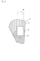
- FIG. 1 is a schematic view of a vehicle in the first embodiment of the present invention.
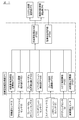
- FIG. 2 is a block diagram of the vehicle control apparatus in the first embodiment of the present invention.
- FIG. 3 is a block diagram of the host vehicle information acquisition unit of FIG.
- Drawing 4 is a figure explaining the judgment of the parking state by the parking state judging part in a 1st embodiment of the present invention (the 1).
- Drawing 5 is a figure explaining the judgment of the parking state by the parking state judging part in a 1st embodiment of the present invention (the 2).
- Drawing 6 is a figure explaining the judgment of the parking state by the parking state judging part in a 1st embodiment of the present invention (the 3).
- FIG. 1 is a schematic view of a vehicle in the first embodiment of the present invention.
- FIG. 2 is a block diagram of the vehicle control apparatus in the first embodiment of the present invention.
- FIG. 3 is a block diagram of the host vehicle information acquisition unit of FIG.
- Drawing 4 is a figure explaining the judgment
- FIG. 7 is a diagram illustrating parking state determination by the parking state determination unit in the first embodiment of the present invention (part 4).
- FIG. 8 is a diagram for explaining parking state determination by the parking state determination unit in the first embodiment of the present invention (part 5).
- FIG. 9 is a block diagram of the peripheral information acquisition unit in FIG.
- FIG. 10 is a block diagram of the control determination information calculation unit of FIG.
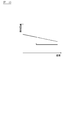
- FIG. 11 is a graph illustrating a first risk base in the first embodiment of the present invention.
- FIG. 12 is a graph illustrating the second risk base in the first embodiment of the present invention.
- FIG. 13 is a diagram illustrating a scene in which warning and vehicle control are executed in the first embodiment of the present invention.
- FIG. 14 is a diagram for explaining a scene in which the priority control determination unit functions in the first embodiment of the present invention (part 1).
- FIG. 15 is a graph for explaining a determination method of the priority control determination unit in the first embodiment of the present invention (part 1).
- FIG. 16 is a diagram for explaining a scene in which the priority control determination unit functions in the first embodiment of the present invention (part 2).
- FIG. 17 is a graph for explaining a determination method of the priority control determination unit in the first embodiment of the present invention (part 2).
- FIG. 18 is a flowchart showing a control procedure of the vehicle control device in the first embodiment of the present invention.
- FIG. 19 is a block diagram of the host vehicle information acquisition unit in the second embodiment of the present invention.
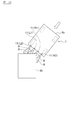
- FIG. 20 is a diagram for explaining the operation of the position and orientation detection unit according to the second embodiment of the present invention (part 1).
- FIG. 21 is a diagram for explaining the operation of the position / orientation detection unit according to the second embodiment of the present invention (part 2).
- FIG. 22 is a block diagram of a control determination information calculation unit in the second embodiment of the present invention.
- FIG. 23 is a graph illustrating a third risk adjustment gain in the second embodiment of the present invention.
- FIG. 24 is a graph for explaining a fourth risk adjustment gain in the second embodiment of the present invention.
- FIG. 25 is a graph illustrating a fifth risk adjustment gain in the third embodiment of the present invention.
- FIG. 26 is a graph illustrating a sixth risk adjustment gain in the third embodiment of the present invention.
- FIG. 27 is a diagram illustrating the operation of the second risk adjustment unit in the fourth embodiment of the present invention.
- FIG. 28 is a diagram for explaining the operation of the second risk adjustment unit in the fifth embodiment of the present invention.
- FIG. 1 is a schematic diagram of a vehicle in the present embodiment
- FIG. 2 is a block diagram of a vehicle control device in the present embodiment
- FIG. 3 is a block diagram of the own vehicle information acquisition unit in FIG. 2,
- FIGS. It is a figure explaining the determination of the parking state by the parking state determination part.
- the vehicle 1 in this embodiment includes a controller 2, a switch sensor 3, a brake lamp 4, an accelerator position sensor 5, a brake pedal position sensor 6, a shift position sensor 7, and a steering sensor. 8, wheel speed sensor 9, acceleration / deceleration sensor 10, nearby obstacle detection device 11, distant obstacle detection device 12, driving force generation device 13, braking force generation device 14, and accelerator pedal reaction force generation A device 15, a notification device 16, and an ignition switch 17 are provided. Below, each sensor, apparatus, etc. are demonstrated. The controller 2 will be described last.
- the switch sensor 3 is a sensor that detects a state of a switch for switching on / off (OFF) of a vehicle control device 100 (described later) in the present embodiment, and outputs the detection result to the controller.
- this switch is provided in the vehicle 1 and is switched on / off by an operation by a driver of the vehicle 1.
- the brake lamp 4 is provided on the rear side 1a of the vehicle 1 and emits light when the brake is operated to notify the other vehicle behind that the vehicle 1 is decelerating.
- the accelerator position sensor 5 detects the position of the accelerator and outputs the detected value to the controller 2.
- the shift position sensor 7 detects the position of the shift lever and outputs the detection result to the controller 2.
- the steering sensor 8 acquires a detected value of the steering angle of the steering wheel and outputs the detected value to the controller 2.
- the wheel speed sensor 9 detects the rotation speed of the wheel of the vehicle 1 and outputs the detected value to the controller 2.
- the acceleration / deceleration sensor 10 detects the acceleration or deceleration of the vehicle 1 and outputs the detected value to the controller 2.
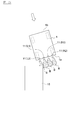
- the nearby obstacle detection device 11 detects a nearby obstacle 18 located in the nearby detection area A that is relatively close to the vehicle 1, and detects the position and speed of the nearby obstacle 18. The value is output to the controller 2. Examples of such a nearby obstacle detection device 11 include sonar.
- the vicinity detection area A is shown with a pattern on the rear side 1 a of the vehicle 1.
- the neighborhood detection area is not particularly limited, for example, the vicinity detection area can be an area within a range of 1 m to 2 m from the vehicle 1.
- each of the nearby obstacle detection devices 11 on the rear side 1a is arranged in order from the top in the figure, the nearby obstacle detection device 11 (R2), the nearby obstacle detection device 11 (R1), and the nearby obstacle detection.
- the device 11 (L1) and the nearby obstacle detection device 11 (L2) are referred to.
- each detectable region B (the part with a pattern in the figure) of the central obstacle detection device 11 (R1), (L1) at the center is at both ends.
- the adjacent obstacle detection devices 11 (R2) and (L2) are relatively wider than the detectable regions B, but this is not particularly limited.
- the detectable area B is an area where each of the nearby obstacle detection devices 11 (R2), (R1), (L1), and (L2) can detect the nearby obstacle 18.
- the distant obstacle detection device 12 detects an obstacle when the obstacle enters the detectable area C and outputs it to the controller 2.
- the distant obstacle detection device 12 can detect a distant obstacle 19 located farther than the above-described vicinity detection area A, and the detectable area C extends farther than the detectable region B of the nearby obstacle detection device 11.
- Two distant obstacle detection devices 12 in the present embodiment are arranged on the rear side 1a and the front side 1b of the vehicle 1, and the direction in which the side obstacle detection device 11 detects the nearby obstacle 18 substantially The distant obstacle 19 located in the same direction is detected.
- An example of such a remote obstacle detection device 12 is a radar.
- the driving force generator 13 is a device that generates the driving force of the vehicle 1 such as an engine or a motor.
- the braking force generator 14 is a device that generates a brake pressure, and is controlled by the controller 2.
- the accelerator pedal reaction force generator 15 is a device that generates a reaction force against the depression of the accelerator, and is controlled by the controller 2.
- the notification device 16 is a device that warns the driver of the presence of the obstacles 18 and 19 based on a command from the controller 2.
- a notification device 16 includes a buzzer capable of generating a warning sound such as “beep”, an indicator capable of blinking a light, and a navigation system capable of blinking around the image. It can be composed of a monitor or the like.
- the ignition switch 17 outputs a start / stop signal for the vehicle 1 to the controller 2 based on a driver on / off switching operation.
- the controller 2 is composed of a computer having a function capable of executing driving support of the vehicle 1 such as an ECU (electronic control unit), for example, as shown in FIG. Part P2, system state selection part P3, control judgment information calculation part P4, braking control operation judgment part P5, braking control part P6, accelerator pedal operation reaction force judgment part P7, accelerator pedal operation reaction force control part P8, a notification determination unit P9, a notification control unit P10, a driving force control determination unit P11, and a driving force control unit P12.
- ECU electronic control unit
- the host vehicle information acquisition unit P1 includes a host vehicle speed / travel distance calculation unit P101, an accelerator opening detection unit P102, a brake pedal position detection unit P103, a shift position detection unit P104, and a switch operation. It has a recognition unit P105, a steer angle calculation unit P106, an acceleration / deceleration calculation unit P107, a host vehicle information output unit P108, and a parking state determination unit P109.
- the own vehicle speed / movement distance calculation unit P101 acquires the detected value of the rotation number of the wheel output from the wheel speed sensor 9, calculates the speed of the vehicle 1, integrates the calculated speed, and Is also calculated. In addition, when calculating the speed of the vehicle 1, you may perform a filter process and an averaging process.
- the accelerator opening detector P102 acquires the detected value of the accelerator position output from the accelerator position sensor 5, detects the accelerator opening (accelerator depression amount), and outputs the detection result to the own vehicle information output unit. Output to P108.
- the brake pedal position detection unit P103 acquires the detection value of the brake pedal position output from the brake pedal position sensor 6, detects whether or not the driver is stepping on the brake, and the detection result is the own vehicle information output unit. Output to P108.
- the shift position detection unit P104 acquires the detection value of the position of the shift lever output from the shift position sensor 7, and outputs the detection value to the host vehicle information output unit P108.
- the switch operation recognition unit P105 detects the detection result of the on / off state of the vehicle control device 100 output from the switch sensor 3, and outputs the detection result to the own vehicle information output unit P108. Further, the switch operation recognition unit P105 acquires a signal output from the ignition sensor 17, detects the on / off state of the engine of the vehicle 1, and outputs the detection results to the own vehicle information output unit P108. .
- the steering angle calculation unit P106 acquires the detected value of the steering angle of the steering wheel output from the steering sensor 8, calculates the steering angle of the steering wheel, and outputs the calculation result to the own vehicle information output unit P108. In addition, when calculating the steering angle in the steering angle calculation unit P106, a filtering process may be performed.
- the acceleration / deceleration calculation unit P107 acquires the acceleration or deceleration detection value of the vehicle 1 output from the acceleration / deceleration sensor 10, calculates the acceleration or deceleration of the vehicle 1, and outputs the calculation result to the own vehicle information output unit. Output to P108.
- the host vehicle information output unit P108 includes the host vehicle speed / movement distance calculation unit P101, the accelerator opening detection unit P102, the brake pedal position detection unit P103, the shift position detection unit P104, the switch operation recognition unit P105, and the steering angle calculation unit P106. Then, the detection results (calculation results) of the acceleration / deceleration calculation unit P107 are collected and output to the system state selection unit P3 and the control determination information calculation unit P4.
- the parking state determination unit P109 acquires various detection values from the own vehicle speed / movement distance calculation unit P101, the shift position sensor P104, the nearby obstacle presence / absence determination unit P203 of the surrounding information acquisition unit P2, which will be described later, and the like.
- 1 is a state of entering the planned parking position (hereinafter referred to as an entry state) or “the vehicle 1 is leaving the parking position (hereinafter referred to as an exit state)”.
- the determination result is output to the control determination information calculation unit P4.
- the entering state and the leaving state are collectively referred to as a parking state.
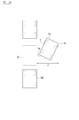
- FIG. 4 illustrates a case where the vehicle 1 is parked in the parking lot D while moving backward.
- the parking state determination unit P109 determines that the vehicle 1 has left the parking position on the condition that the vehicle 1 has moved backward after any of the following states (1) to (3). That is, the state (1) is a state where the vehicle is stopped for a predetermined time (for example, a state where the shift position is parked for 10 seconds or more), and the state (2) is a state where the vehicle speed is a predetermined value ( For example, 1 km / h) or less, and the nearby obstacle 18 is not detected, and the state (3) indicates that the two nearby obstacle detection devices 11 (L1), ( R1) indicates that the nearby obstacle 18 is detected on the traveling direction side (reverse direction in this example) of the vehicle 1, and the distance from the vehicle 1 to the nearby obstacle 18 is a predetermined value (for example, 0.1 m).
- the state is as follows.
- the parking state determination unit P109 determines that the vehicle is in the approach state when either of the following (4) or (5) is satisfied.
- the state of (4) is that the nearby obstacle detection device 11 (L2), (L1), (R1) detects the nearby obstacle 18 and the nearby obstacle detection device 11
- the detection distances LL2, LL1, and LR1 of (L2), (L1), and (R1) are in a state of decreasing in the order of the nearby harmful object detection devices 11 (L2), (L1), and (R1) (LL2 ⁇ LL1 ⁇ LR1).
- the detection distance LL2 is the distance from the vehicle 1 to the nearby obstacle 18 calculated by the controller 2 based on the detection value output by the nearby obstacle detection device 11 (L2).
- the detection distance LL1 is the proximity obstacle.
- the detection distance LR1 is output by the nearby obstacle detection device 11 (R1).
- a detection distance LR2 described later is a distance from the vehicle 1 to the nearby obstacle 18 calculated by the controller 2 based on a detection value detected by the obstacle detection device 11 (R2).
- the detection distances LL2, LL1, LR1, and LR2 are visibly shown by thick lines (the same applies to FIGS. 6 to 8).
- the nearby obstacle detection devices 11 (L2) and (L1) detect the nearby obstacle 18 and the detection distance LL2 is longer than the detection distance LL1 (LL2 ⁇ LL1). ) And the nearby obstacle detection device 11 (R1) is not detecting the nearby obstacle 18.
- the parking state determination unit P109 determines that the greater the difference between the detection distances LL2, LL1, and LR1 (the difference between the maximum value and the minimum value), the higher the vehicle 1 is entering the planned parking position.
- the parking state determination unit P109 determines that the greater the number of the nearby obstacle detection devices 11 that have detected the nearby obstacle 18 is, the higher the vehicle 1 is entering the planned parking position.
- the parking state determination unit P109 determines that the vehicle is in the approach state when either of the following (6) or (7) is satisfied.
- the nearby obstacle detection devices 11 (L1), (R1), (R2) detect the nearby obstacle 18, and the detection distances LL1, LR1, LR2 is a state in which the nearby harmful object detection devices 11 (L1), (R1), and (R2) become longer in this order (LL1 ⁇ LR1 ⁇ LR2).
- the nearby obstacle detection devices 11 (R1) and (R2) detect the nearby obstacle 18, and the detection distance LR1 is shorter than the detection distance LR2 (LR1 ⁇ LR2). ) And the nearby obstacle detection device 11 (L1) is not detecting the nearby obstacle 18.
- the parking state determination unit P109 determines that the greater the difference between the detection distances LR2, LR1, and LL1 (the difference between the maximum value and the minimum value), the higher the vehicle 1 is entering the planned parking position.
- the parking state determination unit P109 determines that the greater the number of the nearby obstacle detection devices 11 that have detected the nearby obstacle 18 is, the higher the vehicle 1 is entering the planned parking position.
- the parking state determination unit P109 determines that the vehicle is leaving when any of the following states (8) to (10) is satisfied.
- the nearby obstacle detection devices 11 (L2), (L1), (R1) detect the nearby obstacle 18, and the detection distances LL2, LL1, LR1 is a state in which the nearby harmful object detection devices 11 (L2), (L1), and (R1) become longer in this order (LL2 ⁇ LL1 ⁇ LR1).
- the nearby obstacle detection device 11 (L2), (L1), (R1) detects the nearby obstacle 18, and the nearby obstacle detection device 11 (R2) detects the nearby obstacle 18.
- the state (9) is a state in which the nearby obstacle detection devices 11 (L2) and (L1) detect the nearby obstacle 18 and the detection distance LL2 is shorter than the detection distance LL1 ( LL2 ⁇ LL1).
- the state (10) is a state in which only the nearby obstacle detection device 11 (L2) detects the nearby obstacle 18 and the detection distance LL2 is a predetermined value (for example, 1 m) or less.
- the parking state determination unit P109 determines that the greater the difference between the detection distances LL2, LL1, and LR1 (the difference between the maximum value and the minimum value), the higher the degree of exit from the parking position in the vehicle 1.
- the parking state determination unit P109 determines that the smaller the number of the nearby obstacle detection devices 11 that have detected the nearby obstacle 18, the higher the degree of exit from the parking position in the vehicle 1.
- the parking state determination unit P109 determines that the vehicle is leaving when any of the following states (11) to (13) is satisfied.
- the nearby obstacle detection devices 11 (L1), (R1), (R2) detect the nearby obstacle 18, and the detection distances LL1, LR1, LR2 is in a state where the nearby harmful object detection devices 11 (L1), (R1), and (R2) are shortened in this order (LL1 ⁇ LR1 ⁇ LR2).
- the nearby obstacle detection device 11 (L1), (R1), (R2) detects the nearby obstacle 18, and the nearby obstacle detection device 11 (L2) detects the nearby obstacle 18.
- the state (12) is a state in which the nearby obstacle detection devices 11 (R1) and (R2) detect the nearby obstacle 18 and the detection distance LR1 is longer than the detection distance LR2 ( LR1 ⁇ LR2).
- the detection distance LR2 is a predetermined value (for example, 1 m) or less.
- the parking state determination unit P109 determines that the greater the difference between the detection distances LL1, LR1, and LR2 (the difference between the maximum value and the minimum value), the higher the degree of exit from the parking position in the vehicle 1.
- the parking state determination unit P109 determines that the smaller the number of the nearby obstacle detection devices 11 that have detected the nearby obstacle 18, the higher the degree of exit from the parking position in the vehicle 1.
- FIG. 9 is a block diagram of the peripheral information acquisition unit in FIG.
- the peripheral information acquisition unit P2 includes a proximity relative distance calculation unit P201, a proximity relative speed calculation unit P202, a proximity obstacle presence / absence determination unit P203, a distant relative distance calculation unit P204, and a distant relative speed.
- a calculation unit P205, a distant obstacle presence / absence determination unit P206, and a peripheral information output unit P207 are included.
- the neighborhood relative distance calculation unit P201 detects the detection distance LL2 from the vehicle 1 to the neighborhood obstacle 18 based on the detection values output from the neighborhood obstacle detection devices 11 (L2), (L1), (R1), and (R2). , LL1, LR1, LR2 are calculated.
- the near relative speed calculation unit P202 calculates the relative speed of the nearby obstacle 18 with respect to the vehicle 1 based on the detection value output from the nearby obstacle detection device 11. In addition, when calculating these distance and relative velocity, you may perform a filter process.
- the nearby obstacle presence / absence determining unit P203 determines the presence / absence of the nearby obstacle 18 based on the calculation results of the nearby relative distance calculating unit P201 and the nearby relative speed calculating unit P202. For example, when any of the calculated detection distances LL2, LL1, LR1, and LR2 is within a predetermined value, the distant obstacle presence / absence determining unit P206 determines that the distant obstacle 19 exists.
- the far relative distance calculation unit P204 calculates the distance between the vehicle 1 and the far obstacle 19 based on the detection value output from the far obstacle detection device 12.
- the far relative speed calculation unit P205 calculates the relative speed of the far obstacle 19 with respect to the vehicle 1 based on the detection value output from the far obstacle detection device 12. Note that filter processing may be performed when calculating these distances and relative velocities.
- the distant obstacle presence / absence determining unit P206 determines the presence or absence of the distant obstacle 19 based on the calculation results of the distant relative distance calculating unit P204 and the distant relative speed calculating unit P205. For example, when the distance calculated by the far relative distance calculating unit P204 is within a predetermined value, the far obstacle presence / absence determining unit P206 determines that the far obstacle 19 exists.
- the peripheral information output unit P207 outputs the determination results of the nearby obstacle presence / absence determination unit P203 and the remote obstacle presence / absence determination unit P206 to the control determination information calculation unit P4, and also includes a vicinity relative distance calculation unit P201 and a vicinity relative speed calculation unit P202.
- the calculation results of the far relative distance calculation unit P204 and the far relative speed calculation unit P205 are output to the control determination information calculation unit P4.
- the system state selection unit P3 determines on / off of the vehicle control device 100 based on the switch state recognized by the switch operation recognition unit P105 of the host vehicle information acquisition unit P1, and calculates the determination result as a control determination information calculation. To the part P4.
- control determination information calculation unit P4 will be described.
- FIG. 10 is a block diagram of the control determination information calculation unit of FIG. 2
- FIG. 11 is a graph for explaining the first risk base in the present embodiment
- FIG. 12 is a graph for explaining the second risk base in the present embodiment
- FIG. 13 is a diagram illustrating a scene in which warning and vehicle control are executed in the present embodiment
- FIGS. 14 and 16 are diagrams illustrating a scene in which the priority control determination unit functions in the present embodiment
- the control determination information calculation unit P4 includes a first risk calculation unit P401, a second risk calculation unit P402, a first risk adjustment unit P403, and a priority control determination unit P4040.
- the system state selection unit P3 determines that the vehicle control device 100 is turned on (actuated), and the shift position detected by the shift position sensor 7 is R (reverse).
- the control determination information calculation unit P4 performs the control calculation.
- the condition for causing the control determination information calculation unit P4 to perform the control calculation may include that the vehicle speed is smaller than a predetermined threshold or that the steering angle is smaller than the predetermined threshold.
- the first risk calculation unit P401 calculates the first risk when it is determined by the peripheral information acquisition unit P2 that the nearby obstacle 18 exists.
- the first risk calculation unit P401 calculates a first risk base RS1 indicating the possibility that the nearby obstacle 18 and the vehicle 1 are in contact with each other, and applies braking to the first risk base RS1.
- the first risk RS1_K1 is calculated by multiplying the coefficient K1 for the brake control determination by the control determination unit P5, and the accelerator pedal reaction force control determination unit P7 performs the accelerator pedal reaction against the first risk base RS1.
- the first risk RS1_K2 is calculated by multiplying the coefficient K2 for force control determination.
- the first risk calculation unit P401 calculates the first risk RS1_K3 by multiplying the first risk base RS1 by the coefficient K3 for notification determination by the notification determination unit P9, and the first risk RS1_K3.
- the first risk RS1_K4 is calculated by multiplying the risk base RS1 by a coefficient K4 for the driving force control determination by the driving force control determination unit P11. In this way, in this embodiment, the weight for each determination is changed by multiplying the first risk base RS1 by the coefficients K1 to K4.
- the first risk base RS1 is calculated by the first risk calculation unit P401 as a distance value that increases in proportion to the speed of the vehicle 1, as shown in FIG. When the vehicle speed is zero, the first risk base RS1 may be set to a predetermined value.
- the first risk base RS1 in the present embodiment is calculated as a distance value, but is not particularly limited, and the first risk base is a time value corresponding to the moving speed of the nearby obstacle 18. You may calculate so that it may become.
- the coefficients K1 to K4 are set to values between 0 and 1 so as to increase in the order of K1, K2, K4, and K3 (K1 ⁇ K2 ⁇ K4 ⁇ K3).
- the first risk also increases in the order of RS1_K1, RS1_K2, RS1_K4, and RS1_K3 (RS1_K1 ⁇ RS1_K2 ⁇ RS1_K4 ⁇ RS1_K3).
- the vehicle 1 is controlled in the order of deceleration by the device 14 (deceleration by increasing brake pressure).
- an unintended sudden deceleration is performed by first giving a warning to inform the driver of the presence of a nearby obstacle, and then executing vehicle control step by step from vehicle control with a low degree of deceleration. The stress that accompanies the driver is suppressed from being applied to the driver.
- the second risk calculation unit P402 calculates the second risk when it is determined by the peripheral information acquisition unit P2 that the distant obstacle 19 exists.
- the second risk calculation unit P402 calculates the bases RS2 and RS3 of the second risk indicating the possibility that the distant obstacle 19 and the vehicle 1 come into contact, like the first risk.
- the second risk is calculated by multiplying the bases RS2 and RS3 of the second risk by coefficients K1 to K4.
- the second risk bases RS2 and RS3 in the present embodiment will be described.
- the second risk base RS2 is calculated as a distance value that increases in proportion to the speed of the vehicle 1, as in FIG. 11 showing the first risk base. Further, when the vehicle speed is zero, the base RS2 may be set to a predetermined value.
- the base RS3 of the second risk is calculated as a time value (for example, 3 seconds) that decreases as the moving speed of the distant obstacle 19 increases.
- the moving speed of the distant obstacle 19 can be calculated by subtracting the speed of the vehicle 1 from the relative speed of the vehicle 1 with respect to the distant obstacle 19.
- the second risk calculation unit P402 in the present embodiment multiplies the bases RS2 and RS3 of the second risk calculated in this way by a coefficient K1 for determination of braking control by the braking control determination unit P5.
- the second risk RS2_K1, RS3_K1 is calculated, and the second risk base RS2, RS3 is multiplied by a coefficient K2 for the accelerator pedal reaction force control determination by the accelerator pedal reaction force control determination unit P7.
- 2 risks RS2_K2 and RS3_K2 are calculated.
- the second risk calculation unit P402 calculates the second risk RS2_K3 and RS3_K3 by multiplying the second risk base RS2 and RS3 by the coefficient K3 for notification determination by the notification determination unit P9.
- the first risk RS2_K4 and RS3_K4 are calculated by multiplying the second risk base RS2 and RS3 by the coefficient K4 for the driving force control determination by the driving force control determination unit P11.
- the weights for the respective determinations are changed by multiplying the bases RS2 and RS3 of the second risk by the coefficients K1 to K4.
- the respective coefficients K1 to K4 are set so as to increase in the order of K1, K2, K4, and K3 (K1 ⁇ K2 ⁇ K4 ⁇ K3).
- a value between 0 and 1 is set.
- the second risk also increases in the order of RS2_K1, RS2_K2, RS2_K4, RS2_K3 (RS2_K1 ⁇ RS2_K2 ⁇ RS2_K4 ⁇ RS2_K3), and increases in the order of RS3_K1, RS3_K2, RS3_K4, RS3_K3 ⁇ RS3_K1 ⁇ RS3_K1 ⁇ RS3_K1 ⁇ RS3_K1 ⁇ RS3_K1 ⁇ RS3_K1 RS3_K3_K3).
- the vehicle 1 is controlled step by step in the order of deceleration by the device 14 (deceleration by increasing brake pressure).
- the 1st detection area C1 in the figure is an area
- a warning is given to notify the driver of the presence of a distant obstacle, and then vehicle control is executed step by step from vehicle control with a low degree of deceleration. Thereby, it is suppressed that the stress accompanying the sudden deceleration which is not intended is applied to a driver.
- the first risk adjustment unit P404 adjusts the first and second risks calculated as described above based on the determination result of the parking state determination unit P109 of the host vehicle information acquisition unit P1. In the present embodiment, risk adjustment will be described on behalf of the first risk RS1_K3 and the second risk RS2_K3.
- the first risk adjusting unit P404 provides a warning for notifying the driver of the presence of the nearby obstacle 18 and the far obstacle 19
- the first risk RS1_K3 is adjusted to be increased and the second risk RS2_K3 is adjusted to be reduced so that the first risk RS1_K3 can be preferentially executed rather than the warning for notifying the driver of the presence of.
- Such risk adjustment is performed by multiplying the first and second risks RS1_K3 and RS2_K3 by a risk adjustment gain.
- the first risk adjustment gain to be multiplied by the first risk RS1_K3 is G10
- the second risk adjustment gain to be multiplied by the second risk RS2_K3 is G20.
- the first risk after the first risk adjustment is indicated by a first risk RS1_K3_G10
- the second risk after the first risk adjustment is indicated by a second risk RS2_K3_G20.
- the first risk adjustment unit P404 sets the first risk adjustment gain G10 to a relatively large value (for example, a value of 1 or more). Set and multiply the first risk adjustment gain G10 by the first risk RS1_K3. Further, in this case, the first risk adjustment unit P404 sets the second risk adjustment gain G20 to a relatively small value (for example, a value between 0 and 1) and sets the second risk adjustment gain P20 to the second risk adjustment gain P20. The adjustment gain G20 is multiplied by the second risk RS2_K3.
- the higher the degree that the vehicle 1 is about to park at the planned parking position the higher the first risk RS1_K3 may be adjusted, and the second risk RS2_K3 may be adjusted to be smaller. Thereby, it is possible to more appropriately execute the determination as to whether or not to execute the warning or the vehicle control according to the parking state of the vehicle 1.
- the first risk adjustment unit P404 adjusts both the first and second risks RS1_K3 and RS2_K3, but is not particularly limited, and even if only one of them is adjusted. Good.
- the first risk RS1_K3 may not be adjusted, and only the second risk RS2_K3 may be adjusted to be small.
- the first risk RS1_K3 may be adjusted to be increased, and the second risk RS2_K3 may not be adjusted.
- the first risk adjustment unit P404 gives a warning for notifying the driver of the presence of the distant obstacle 19 in the vicinity obstacle.
- the first risk RS1_K3 is adjusted to be small and the second risk RS2_K3 is adjusted to be large so that the warning can be executed preferentially over the warning for notifying the driver of the presence of the object 18.
- the first risk adjustment unit P404 sets the first risk adjustment gain G10 to a relatively small value (eg, 0 to 1).
- the first risk adjustment gain G10 is multiplied by the first risk RS1_K3.
- the first risk adjustment unit P404 sets the second risk adjustment gain G20 to a relatively large value (for example, a value of 1 or more), and the second risk adjustment gain G20. Is multiplied by the second risk RS2_K3.
- the higher the degree that the vehicle 1 is leaving the parking position the smaller the first risk RS1_K3 may be adjusted, and the second risk RS2_K3 may be adjusted to be larger. Thereby, it is possible to more appropriately execute the determination as to whether or not to execute the warning or the vehicle control according to the parking state of the vehicle 1.
- the first risk adjustment unit P404 adjusts both the first and second risks RS1_K3 and RS2_K3, but is not particularly limited, and only one of them may be adjusted. .
- the first risk RS1_K3 may not be adjusted, and only the second risk RS2_K3 may be adjusted to be increased.
- the first risk RS1_K3 may be adjusted to be small, and the second risk RS2_K3 may not be adjusted.
- the risk adjustment for the first risk RS1_K1, RS1_K2, RS1_K4 is the same as described above, and the risk adjustment for the second risk RS2_K1, RS2_K2, RS3_K4, RS3_K1, RS3_K2, RS3_K3, RS3_K4 is also performed. Same as above.
- the priority control determination unit P ⁇ b> 404 is configured when an obstacle 18 a different from the nearby obstacle 18 detected by the nearby obstacle detection device 11 interrupts between the nearby obstacle 18 and the vehicle 1.
- the interruption of the obstacle 18a is detected as follows. That is, when the vehicle 1 moves so as to approach the nearby obstacle 18, the controller 2 (near relative distance calculation unit P ⁇ b> 201) determines that the distance between the vehicle 1 and the nearby obstacle 18 is gradually shortened. The distance is calculated.
- the nearby obstacle detection device 11 detects the obstacle 18a, as shown in FIG.
- the detection distance is suddenly shortened.
- the dotted line in a figure has shown the change of the detection distance when the obstruction 18a does not interrupt. Even when the vehicle 1 does not detect the nearby obstacle 18, the obstacle 18 a suddenly appears from the side of the vehicle 1, thereby causing a sudden change in the detection distance.
- the interruption of the obstacle 18a is detected based on such a sudden change in the detection distance.
- the detection distance is shorter than a predetermined value (for example, 1.5 m) and the past detection distance (detection distance several seconds ago or the detection distance calculated by the controller 2 one cycle before) that has been detected and the current
- a predetermined value for example, 20 cm
- the priority determination unit P404 when it is determined by the priority determination unit P404 that there has been an interruption by the obstacle 18a, the priority determination unit P404 has priority over the warning and vehicle control based on the first and second risks, A signal for executing a warning or a vehicle control for the obstacle 18a that has been interrupted is output. Furthermore, the priority determination unit P404 outputs a signal for executing the warning and the vehicle control for the obstacle 18a that has been interrupted even when the warning and the vehicle control based on the first and second risks are not executed.
- the priority control determination unit P ⁇ b> 404 is configured so that when the obstacle 18 b is actively approaching the vehicle 1, the approaching obstacle is the same as when the obstacle 18 a is interrupted as described above.
- a warning for the object 18b and a signal for executing vehicle control are output to the braking control operation determination unit P5, the accelerator pedal operation reaction force determination unit P7, the notification determination unit P9, and the driving force control determination unit P11.
- the approach of the obstacle 18b is detected as follows. That is, when the vehicle 1 is moving toward the stopped obstacle 18, the detection distance is shortened by the distance traveled according to the vehicle speed of the vehicle 1.
- the detection distance is shorter than the distance traveled.
- the dotted line in a figure has shown the change of the detection distance when the obstruction 18b has stopped temporarily.
- the approach of the obstacle 18b is detected based on such a change in the detection distance. More specifically, it is determined that the obstacle 18b is approaching the vehicle 1 because the difference between the detection distance and the movement distance according to the vehicle speed is equal to or greater than a predetermined value (for example, 15 cm). be able to. Alternatively, the speed of the obstacle 18b is calculated by differentiating the difference with time, and when the calculated speed is equal to or greater than a predetermined value (1.5 km / h), the obstacle 18b It can also be judged that it is approaching.
- a predetermined value for example, 15 cm
- the priority determination unit P404 determines that the obstacle 18b has approached, the priority determination unit P404 has priority over the warning and vehicle control based on the first and second risks, A signal for executing warning or vehicle control for the approaching obstacle 18b is output. Furthermore, the priority determination unit P404 outputs a signal for executing the warning and the vehicle control for the approaching obstacle 18b even when the warning and the vehicle control based on the first and second risks are not executed.
- the braking control determination unit P5 is calculated by the first risk calculation unit P401, and the first risk RS1_K1_G10 (distance value) adjusted by the first risk adjustment unit P403 is detected by the nearby obstacle detection device 11.
- the distance is larger than the distance LL1 (here, the detection distance LL1 will be described as a representative) (RS1_K1_G10> LL1)
- a signal for executing the braking control is output to the braking control unit P6.
- the braking control here means the control of the brake pressure.
- the braking control determination unit P5 is calculated by the second risk calculation unit P402, and the second risk RS2_K1_G20 (distance value) adjusted by the first risk adjustment unit P403 is the far obstacle detection device 12. Even when the detected distance LF is larger than (RS2_K1_G20> LF), a signal for executing the braking control is output to the braking control unit P6.
- the braking control determination unit P5 is calculated by the second risk calculation unit P402, and the second risk RS3_K1_G20 (time value) adjusted by the first risk adjustment unit P403 is TTC (Tim To collision). Even if larger than (RS3_K1_G20> TTC), a signal for executing the braking control is output to the braking control unit P6.
- the TTC here can be calculated by the following equation (1).
- TTC detection distance / relative speed (1)
- the detection distance in the above equation (1) is the detection distance of the far obstacle detection device 12, and the relative speed is the relative speed of the vehicle 1 with respect to the far obstacle 19.
- the brake control unit P6 acquires the above signal from the brake control determination unit P5
- the brake control unit P6 increases the brake pressure at a predetermined rate of change, and when the predetermined brake pressure is reached, the braking force is maintained so as to maintain the brake pressure.
- the generator 14 is controlled.
- the brake control unit P6 brakes at a predetermined rate of change when a predetermined brake pressure is maintained for a predetermined time (for example, 0.8 seconds) or when a predetermined time elapses after the vehicle 1 stops.
- the braking force generator 14 is controlled so that the pressure is reduced to zero.
- the predetermined brake pressure, the predetermined time, and the predetermined change rate may be changed according to the speed of the vehicle 1 and the distance from the vehicle 1 to the obstacles 18 and 19.
- the braking control determination unit P5 determines that the braking control based on both the first risk RS1_K1_G10 and the second risk RS2_K1_G20 and RS3_K1_G20 is necessary, the braking control unit P6 The braking control based on the risk RS1_K1_G10 is prioritized and executed.
- the accelerator pedal reaction force determination unit P7 is calculated by the first risk calculation unit P401, and the first risk RS1_K2_G10 adjusted by the first risk adjustment unit P403 is the detection distance of the nearby obstacle detection device 11.
- LL1 which will be described as a representative detection distance LL1 (RS1_K2_G10> LL1)
- a signal for executing the accelerator pedal operation reaction force control is output to the accelerator pedal operation reaction force control unit P8.
- the accelerator pedal operation reaction force determination unit P7 is calculated by the second risk calculation unit P402, and the second risk RS2_K2_G20 adjusted by the first risk adjustment unit P403 is calculated by the remote obstacle detection device 12.
- a signal for executing the accelerator pedal operation reaction force control is output to the accelerator pedal operation reaction force control unit P8.
- the accelerator pedal operation reaction force determination unit P7 is also calculated when the second risk RS3_K2_G20 calculated by the second risk calculation unit P402 and adjusted by the first risk adjustment unit P403 is larger than TTC. (RS3_K2_G20> TTC), a signal for executing the accelerator pedal operation reaction force control is output to the accelerator pedal operation reaction force control unit P8.
- the accelerator pedal operation reaction force control unit P8 acquires the above signal from the accelerator pedal operation reaction force determination unit P7, and increases the accelerator pedal reaction force at a predetermined change rate when the driver depresses the accelerator pedal.
- the accelerator pedal reaction force generator 15 is controlled so that
- the accelerator pedal reaction force control unit P8 controls the accelerator pedal reaction force generator 15 to maintain the state. Thereafter, when a predetermined time (for example, 0.8 seconds) elapses, the accelerator pedal operation reaction force control unit P8 decreases the accelerator pedal reaction force command value to zero at a predetermined change rate.
- the predetermined reaction force command value, the predetermined time, and the predetermined change rate may be changed according to the speed of the vehicle 1 and the distance from the vehicle 1 to the obstacles 18 and 19.
- the pedal operation reaction force control unit P8 preferentially executes the accelerator pedal operation reaction force control based on the first risk RS1_K2_G10.
- the notification determination unit P9 is calculated by the first risk calculation unit P401, and the first risk RS1_K3_G10 adjusted by the first risk adjustment unit P403 is the detection distance LL1 (detection distance) of the nearby obstacle detection device 11. (RS1_K3_G10> LL1), a signal that causes the notification device 16 to warn is output to the notification control unit P10.
- the notification determination unit P9 calculates the second risk RS2_K3_G20 calculated by the second risk calculation unit P402 and adjusted by the first risk adjustment unit P403 based on the detection distance LF of the far obstacle detection device 12. Is larger (RS2_K3_G20> LF), a signal that causes the notification device 16 to warn is output to the notification control unit P10.
- the notification determination unit P9 is also calculated when the second risk RS3_K3_G20 calculated by the second risk calculation unit P402 and adjusted by the first risk adjustment unit P403 is larger than TTC (RS3_K3_G20> TTC). ), A signal to alert the notification device 16 is output to the notification control unit P10.
- the notification control unit P10 When the notification control unit P10 acquires the above signal from the notification determination unit P9, the notification control unit P10 repeatedly outputs a warning sound or a signal for turning on / off the light to the notification device 16.
- a signal may be output so that the interval at which the buzzer is turned on is shortened as the obstacles 18 and 19 and the vehicle 1 approach each other. That is, when the obstacles 18 and 19 are away from the vehicle 1, an intermittent sound such as “beep” is generated in the buzzer, and when the obstacles 18 and 19 are approaching the vehicle 1, A continuous sound such as “beep” may be generated in the buzzer. Thereby, the driver can know the approach of the obstacles 18 and 19 by hearing. Also, the warning for the nearby obstacle 18 and the warning for the far obstacle 19 may be different warning sounds.
- the notification determination unit P9 determines that a warning based on both the first risk RS1_K3_G10 and the second risk RS2_K3_G20 and RS3_K3_G20 is necessary, the notification control unit P10 A warning based on RS1_K3_G10 is preferentially executed.
- the driving force control determination unit P11 is calculated by the first risk calculation unit P401, and the first risk RS1_K4_G10 adjusted by the first risk adjustment unit P403 is the detection distance LL1 ( If it is greater than (detection distance LL1 as a representative) (RS1_K4_G10> LL1), a signal for executing the driving force control is output to the driving force control unit P12.
- the driving force control determination unit P11 is calculated by the second risk calculation unit P402, and the second risk RS2_K4_G20 adjusted by the first risk adjustment unit P403 is the detection distance of the distant obstacle detection device 12. Even when larger than LF (RS2_K4_G20> LF), a signal for executing the driving force control is output to the driving force control unit P12.
- the driving force control determination unit P11 is also calculated when the second risk RS3_K4_G20 calculated by the second risk calculation unit P402 and adjusted by the first risk adjustment unit P403 is larger than TTC (RS3_K4_G20). > TTC), a signal for executing the driving force control is output to the driving force control unit P12.
- the driving force control unit P12 When the driving force control unit P12 acquires the above signal from the driving force control determination unit P11, the driving force control unit P12 performs the following control on the driving force generation device 13. That is, the driving force control unit P12 calculates the amount of decrease in the accelerator opening, reduces the accelerator opening to a predetermined value at a predetermined change rate, maintains the state for a predetermined time, and then returns the accelerator opening to the original value.
- the driving force generator 13 is controlled so that the throttle opening shown in the following equation (2) is obtained. Note that the accelerator opening reduction amount, the predetermined change rate, and the predetermined time may be changed according to the vehicle speed of the vehicle 1 and the distance from the vehicle 1 to the obstacles 18 and 19.
- the driving force control determination unit P11 determines that the driving force control based on both the first risk RS1_K4_G10 and the second risk RS2_K4_G20 and RS3_K4_G20 is necessary, the driving force control unit P12 The control based on the first risk RS1_K4_G10 is preferentially executed.
- the vehicle control device 100 includes the controller 2, the nearby obstacle detection device 11, the far obstacle detection device 12, and the driving force generation device 13 described above.
- the braking force generator 14, the accelerator pedal reaction force generator 15, and the notification device 16 are configured.
- FIG. 18 is a flowchart showing a control procedure of the vehicle control device in the present embodiment.
- step S1 the controller 2 (first and second risk calculation units P401, P402) calculates the first risk RS1_K1, RS1_K2, RS1_K3, RS1_K4, and the second risk RS2_K1, RS2_K2, RS2_K3, RS2_K4, RS3_K1, RS3_K2, RS3_K3, and RS3_K4 are calculated.
- step S3 the controller 2 (parking state determination unit P109) determines whether the vehicle 1 is in a state of entering the planned parking position or in a state of leaving the parking position.
- step S5 the controller 2 (first risk adjustment unit P403) performs risk adjustment. For example, if it is determined in step S3 that the vehicle 1 is in the approaching state, the first risk RS1_K3 is multiplied by a relatively large risk adjustment gain G10, and the second risk RS2_K3 is relatively small. Multiply by G20 (G10> G20).
- G10 G10> G20
- the first and second risks RS1_K3 and RS2_K3 are described as representatives. Further, as described above, only one of the first and second risks may be adjusted for risk, and the other of the first and second risks may not be adjusted for risk.
- step S7 the controller 2 (braking control operation determination unit P5, accelerator pedal operation reaction force determination unit P7, notification determination unit P9, and driving force control determination unit P11) determines whether to perform warning or vehicle control. To do. If it is determined in step S7 that warning or vehicle control is to be performed, the process proceeds to step S9.
- step S7 if it is determined in step S7 that no warning or vehicle control is performed, the process proceeds to step S8.
- step S8 it is determined whether or not there is another obstacle 18a interrupted between the nearby obstacle 18 and the vehicle 1, or whether or not there is an obstacle 18b approaching the vehicle 1. If it is determined in step S8 that such obstacles 18a and 18b exist, the process proceeds to step S9. If it is determined that no obstacles 18a and 18b exist, the control of the vehicle control device 100 is controlled. finish.
- step S9 the driver is warned of the presence of the obstacles 18 and 19 and vehicle control such as braking force control is executed.
- the coefficients K1 to K4 used in the first and second risk calculation units P401 and P402 increase in the order of K1, K2, K4, and K3 (K1 ⁇ K2 ⁇ K4).
- K3 K1 ⁇ K2 ⁇ K4.
- warning by the notification device 16 ⁇ deceleration by the driving force generator 13 (deceleration by reduction of the accelerator opening) ⁇ reaction force generation on the accelerator pedal by the accelerator pedal reaction force generator 15 ⁇ deceleration by the braking force generator 14
- the vehicle 1 is controlled in the order of (deceleration due to increase in brake pressure).
- step S7 when it is determined in step S7 that warning or vehicle control is not performed, the process proceeds to step S8.
- warning or vehicle control is required in step S7.
- the process may proceed to step S8 also when it is determined that.
- the vehicle 1 may be controlled in the order of deceleration by the power generation device 14.
- the first risk (base) indicating the possibility of the vehicle coming into contact with a nearby obstacle is calculated, and the second risk indicating the possibility that the vehicle will come into contact with a distant obstacle.
- Base is calculated, and the warning or vehicle control based on one of the first and second risks is performed based on the state in which the vehicle enters the planned parking position or the state in which the vehicle leaves the parking position.
- the first and second risks are adjusted so that the warning or vehicle control based on the other of the second risks is executed with priority.
- the priority of warning and vehicle control for obstacles that are unlikely to come into contact with the vehicle is lowered, and the priority of warning and vehicle control for obstacles that are likely to come into contact with the vehicle is raised. is doing.
- an appropriate warning is given to an obstacle that the driver needs to pay attention to, or appropriate vehicle control is performed to avoid contact with the obstacle, and an unnecessary warning is issued.
- warning by the notification device ⁇ deceleration by the driving force generator (deceleration by reducing the accelerator opening) ⁇ generation of reaction force to the accelerator pedal by the accelerator pedal reaction force generator ⁇ deceleration by the braking force generator ( The vehicle is controlled in the order of deceleration by increasing brake pressure).
- the driver since the warning is always generated before the vehicle control is executed, the driver can know the possibility that the vehicle control is executed by this warning. Thereby, it can suppress that the stress accompanying execution of sudden vehicle control is applied to a driver.
- deceleration by the driving force generator (deceleration by reducing the accelerator opening) ⁇ generation of reaction force to the accelerator pedal by the accelerator pedal reaction force generator ⁇ deceleration by the braking force generator (by increasing brake pressure)
- warning or vehicle control since it is determined whether or not to execute warning or vehicle control based on the risk indicating the possibility that the vehicle and the obstacle come into contact with each other, there is a nearby obstacle near the vehicle. However, if a distant obstacle approaching at a high speed from a distance is detected, warning or vehicle control for the distant obstacle can be performed. Accordingly, it is possible to execute an appropriate warning or vehicle control that allows the driver to recognize a potential risk with respect to a distant obstacle.
- warning and vehicle control for the interrupted obstacle are executed preferentially, so that the driver can be surely recognized of the interrupted obstacle.
- the vicinity obstacle detection device 11 on the rear side 1a when determining whether or not the vehicle 1 is in the retreat state due to the backward movement, the vicinity obstacle detection device 11 on the rear side 1a is used.
- An obstacle located on the front side 1b of the vehicle 1 may be detected using the object detection device 11 or the remote obstacle detection device 12, and a warning or the like may be executed for the detected obstacle.
- the driver can be alerted to the obstacle located on the side opposite to the traveling direction (reverse direction in this example).
- FIG. 19 is a block diagram of the host vehicle information acquisition unit in the present embodiment
- FIGS. 20 and 21 are diagrams for explaining the operation of the position and orientation detection unit in the present embodiment
- FIG. FIG. 23 is a block diagram
- FIG. 23 is a graph for explaining the third risk adjustment gain in the present embodiment
- FIG. 24 is a graph for explaining the fourth risk adjustment gain in the present embodiment.
- the configurations of the host vehicle information acquisition unit P1 and the control determination information calculation unit P4 of the controller 2 are different from those in the first embodiment, but the other configurations are the same as those in the first embodiment. Only the parts different from the first embodiment will be described below, and the same parts as those in the first embodiment are denoted by the same reference numerals and the description thereof will be omitted.
- the host vehicle information acquisition unit P1 of the controller 2 in the present embodiment includes a position / orientation detection unit P110 that detects the position and orientation of the vehicle 1 with respect to the nearby obstacle 18, as shown in FIG.
- the position / orientation detection unit P ⁇ b> 110 estimates the direction of the traveling direction of the vehicle 1 with respect to the nearby obstacle 18 based on the detection result of the nearby obstacle by the nearby obstacle detection device 11. .
- the traveling direction is a concept including not only the forward direction but also the backward direction.
- 20 and 21 illustrate a state in which the vehicle 1 is approaching the nearby obstacle 18 while moving backward.
- the nearby obstacle detecting device 11 (L2) detects the nearby obstacle 18, and the nearby obstacle detecting devices 11 (L1), (R1), and (R2) are the nearby obstacle 18. Is not detected, the traveling direction of the vehicle 1 is estimated to be away from the nearby obstacle 18.
- the position / orientation detection unit P110 outputs an estimation result of the traveling direction of the vehicle 1 to a second risk adjustment unit P405 (described later).
- the direction of the traveling direction of the vehicle 1 with respect to the nearby obstacle 18 is estimated by the obstacle detection sensor 11 as described above, but the method of estimating the direction of the traveling direction of the vehicle 1 is not particularly limited.
- a camera may be provided in the vehicle, the periphery of the vehicle 1 may be imaged, and the direction of the traveling direction of the vehicle 1 with respect to the nearby obstacle 18 may be calculated by image processing.
- control determination information calculation unit P4 in the present embodiment has a second risk adjustment unit P405 as shown in FIG.
- the second risk adjustment unit P405 adjusts the first and second risks adjusted by the first risk adjustment unit P403 based on the direction of the traveling direction of the vehicle 1 estimated by the position and orientation detection unit P110. To do.
- the traveling direction of the vehicle 1 is a direction toward the nearby obstacle 18, the first risk RS1_K1_G10, RS1_K2_G10, RS1_K3_G10, RS1_K4_G10 (hereinafter, the reference number is simply omitted and the first risk
- the second risk RS2_K1_G20, RS2_K2_G20, RS2_K3_G20, RS2_K4_G20, RS3_K1_G20, RS3_K2_G20, RS3_K3_G20, and RS3_K4 (hereinafter referred to as a sign). Adjust as follows.
- the first risk is adjusted to be reduced and the second risk is adjusted to be increased.
- Such risk adjustment is performed as follows. That is, the first risk is multiplied by the third risk adjustment gain G11, and the second risk is multiplied by the fourth risk adjustment gain G21.
- the first risk adjustment gain G11 is a value corresponding to the direction of the vehicle 1 in the traveling direction. More specifically, the third risk adjustment gain G11 multiplied by the first risk is calculated so as to increase as the traveling direction of the vehicle 1 is directed toward the nearby obstacle 18, as shown in FIG. (For example, a value of 1 or more in the state of FIG. 20) is calculated so as to decrease as the traveling direction of the vehicle 1 moves away from the nearby obstacle 18 (for example, 0 to 0 in the state of FIG. 21). Value between 1).
- the fourth risk adjustment gain G21 multiplied by the second risk is calculated so as to decrease as the traveling direction of the vehicle 1 is directed toward the nearby obstacle 18 (for example, 20 (value between 0 and 1 in the state of FIG. 20) and is calculated so as to increase as the traveling direction of the vehicle 1 moves away from the nearby obstacle 18 (for example, a value of 1 or more in the state of FIG. 21). ).
- the control procedure of the vehicle control device 100 in the present embodiment includes a risk adjustment step (step S5) by the first risk adjustment unit P403 in the first embodiment and a priority determination step (step S7) by the priority control determination unit P404.
- a risk adjustment step S6 by the second risk adjustment unit P405.
- illustration by a flowchart is abbreviate
- step S6 as described above, the first risk is adjusted to increase as the traveling direction of the vehicle 1 is directed toward the nearby obstacle 18, and the second risk is adjusted to be reduced. Then, the first risk is adjusted to be smaller and the second risk is adjusted to be larger as the traveling direction of the vehicle 1 is away from the nearby obstacle 18.
- the warning and vehicle control based on the first risk are easier to be executed as the traveling direction of the vehicle is toward the nearby obstacle, and the traveling direction of the vehicle is the nearby obstacle. The further away from the direction, the easier it is to execute warning and vehicle control based on the second risk.
- “to facilitate execution of warning and vehicle control” includes advancing the timing of warning and vehicle control.
- warning and vehicle control in the present embodiment includes delaying the timing of warning and vehicle control.
- the priority of warning and vehicle control for obstacles that are unlikely to come into contact with the vehicle is lowered, and the priority of warning and vehicle control for obstacles that are likely to come into contact with the vehicle are set. Since the first and second risks are adjusted by the first risk adjustment unit so as to increase, it is possible to reduce the stress applied to the driver.
- warning and vehicle control for the interrupted obstacle are preferentially executed, so that the driver can reliably recognize the interrupted obstacle.
- warning or vehicle control since it is determined whether or not to perform warning or vehicle control based on the risk indicating the possibility of contact between the vehicle and an obstacle, appropriate warning or vehicle control is executed. Can do.
- warning by the notification device ⁇ deceleration by the driving force generator (deceleration by reducing the accelerator opening) ⁇ reaction force generation on the accelerator pedal by the accelerator pedal reaction force generator ⁇ deceleration by the braking force generator Since the vehicle is controlled in the order of (deceleration due to an increase in brake pressure), it is possible to suppress the driver from being subjected to stress due to the sudden execution of vehicle control.
- both the first risk and the second risk are adjusted based on the traveling direction of the vehicle, but only one of the risks may be adjusted.
- FIG. 25 is a graph for explaining the fifth risk adjustment gain in this embodiment
- FIG. 26 is a graph for explaining the sixth risk adjustment gain in this embodiment.
- the configurations of the position / orientation detection unit P110 and the second risk adjustment unit P405 are different from those of the second embodiment, but the other configurations are the same as those of the second embodiment. That is, this embodiment is the same as the first embodiment except that the controller 2 includes the position / orientation detection unit P110 and the second risk adjustment unit P405. Only the parts different from those of the first and second embodiments will be described below, and the same parts as those of the first and second embodiments are denoted by the same reference numerals and the description thereof is omitted. In the present embodiment as well, as in the second embodiment, the description of the symbols for the first and second risks is omitted.
- the position and orientation detection unit P110 in the present embodiment detects the distance from the vehicle 1 to the nearby obstacle 18.
- the position / orientation detection unit P110 is provided in the host vehicle information acquisition unit P1 as in the second embodiment.
- the position and orientation detection unit P110 of the surrounding information acquisition unit P2 is not limited to a specific position. You may make it function as attitude
- the second risk adjustment unit P405 in the present embodiment multiplies the first risk by the fifth risk adjustment gain, and adjusts the risk by multiplying the second risk by the sixth risk adjustment gain. Execute.
- the fifth risk adjustment gain is calculated so as to increase in proportion to a decrease in the distance detected by the position and orientation detection unit P110, and is proportional to an increase in the distance. Is calculated to be smaller. For example, when the distance is shorter than a predetermined value, the fifth risk adjustment gain is set to a value of 1 or more, and when the distance is longer than the predetermined value, the fifth risk adjustment gain is set to 0 to 1. It can be a value between.
- the sixth risk adjustment gain is calculated so that the distance detected by the position / orientation detection unit P110 decreases as the distance decreases, and the distance increases. It is calculated so as to increase in proportion. For example, when the distance is shorter than a predetermined value, the sixth risk adjustment gain is set to a value between 0 and 1, and when the distance is longer than the predetermined value, the sixth risk adjustment gain is set to 1. It can be set as the above value.
- the control procedure of the vehicle control device 100 in the present embodiment is also based on the risk adjustment step (step S5) by the first risk adjustment unit P403 in the first embodiment and the priority control determination unit P404. Between the priority determination step (step S7), a risk adjustment step S6 by the second risk adjustment unit P405 is provided.
- illustration by a flowchart is abbreviate
- step S6 as described above, as the distance from the vehicle 1 to the nearby obstacle 18 becomes shorter, the first risk is adjusted to be increased and the second risk is adjusted to be reduced. As the distance from to the nearby obstacle 18 becomes longer, the first risk is adjusted to be smaller and the second risk is adjusted to be larger.
- “to facilitate execution of warning and vehicle control” includes advancing the timing of warning and vehicle control.
- warning warning and vehicle control in the present embodiment includes delaying the timing of warning and vehicle control.
- the priority of warning and vehicle control for obstacles that are unlikely to come into contact with the vehicle is lowered, and the priority of warning and vehicle control for obstacles that are likely to come into contact with the vehicle are set. Since the first and second risks are adjusted by the first risk adjustment unit so as to increase, it is possible to reduce the stress applied to the driver.
- warning and vehicle control for the interrupted obstacle are preferentially executed, so that the driver can reliably recognize the interrupted obstacle.
- warning or vehicle control since it is determined whether or not to perform warning or vehicle control based on the risk indicating the possibility of contact between the vehicle and an obstacle, appropriate warning or vehicle control is executed. Can do.
- warning by the notification device ⁇ deceleration by the driving force generator (deceleration by reducing the accelerator opening) ⁇ reaction force generation on the accelerator pedal by the accelerator pedal reaction force generator ⁇ deceleration by the braking force generator Since the vehicle is controlled in the order of (deceleration due to an increase in brake pressure), it is possible to suppress the driver from being subjected to stress due to the sudden execution of vehicle control.
- both the first risk and the second risk are adjusted based on the distance from the vehicle to the nearby obstacle.
- only one of the risks may be adjusted.
- FIG. 27 is a diagram for explaining the operation of the second risk adjustment unit in the present embodiment.
- the configurations of the position / orientation detection unit P110 and the second risk adjustment unit P405 are different from those of the second embodiment, but the other configurations are the same as those of the second embodiment. That is, this embodiment is the same as the first embodiment except that the controller 2 includes the position / orientation detection unit P110 and the second risk adjustment unit P405. Only the parts different from those of the first and second embodiments will be described below, and the same parts as those of the first and second embodiments are denoted by the same reference numerals and the description thereof is omitted. In the present embodiment as well, as in the second embodiment, the description of the symbols for the first and second risks is omitted.
- the position / orientation detection unit P110 in the present embodiment calculates an estimated travel locus E of the vehicle 1 based on the steering angle of the steering hole calculated by the steering angle calculation unit P106, and performs the estimation.
- a distance F (hereinafter referred to as an estimated distance) between the travel locus E and the nearby obstacle 18 is calculated.
- the estimated distance F in the present embodiment is a distance between a point closest to the nearby obstacle 18 in the estimated traveling locus E and the center line CL of the nearby obstacle 18.
- the vehicle 1 is shown moving backward.
- the second risk adjustment unit P405 in the present embodiment performs risk adjustment by multiplying the first risk by the seventh risk adjustment gain and multiplying the second risk by the eighth risk adjustment gain. .
- the seventh risk adjustment gain is calculated so as to increase in proportion to the estimated distance F being shortened, and is proportional to the estimation distance F becoming longer. Is calculated so as to be smaller. For example, when the estimated distance F is shorter than a predetermined value, the seventh risk adjustment gain is set to 1 or more, and when the estimated distance F is longer than the predetermined value, the seventh risk adjustment gain is set to 0 to The value can be between 1.
- the eighth risk adjustment gain is calculated so that the estimated distance F becomes smaller as the estimated distance F becomes shorter, and is proportional to the estimated distance F becomes longer. Is calculated so as to increase. For example, when the estimated distance F is shorter than a predetermined value, the eighth risk adjustment gain is set to a value between 0 and 1, and when the estimated distance F is longer than the predetermined value, the eighth risk adjustment gain is set. Can be 1 or more.
- the control procedure of the vehicle control device 100 in the present embodiment is also based on the risk adjustment step (step S5) by the first risk adjustment unit P403 in the first embodiment and the priority control determination unit P404. Between the priority determination step (step S7), a risk adjustment step S6 by the second risk adjustment unit P405 is provided.
- illustration by a flowchart is abbreviate
- step S6 the first risk is adjusted so as to increase as the estimated distance F becomes shorter, and the second risk is adjusted so as to become smaller. As the estimated distance F becomes longer, the first risk increases. The risk is adjusted so as to be reduced, and the second risk is adjusted so as to be increased.
- warning and the vehicle control As described above, also in the present embodiment, as the vehicle approaches the nearby obstacle, it becomes easier to execute the warning and the vehicle control based on the first risk, and as the vehicle moves away from the nearby obstacle, the second It makes it easier to execute warnings and vehicle control based on risk.
- “to facilitate execution of warning and vehicle control” includes advancing the timing of warning and vehicle control.
- warning warning and vehicle control in the present embodiment includes delaying the timing of warning and vehicle control.
- the priority of warning and vehicle control for obstacles that are unlikely to come into contact with the vehicle is lowered, and the priority of warning and vehicle control for obstacles that are likely to come into contact with the vehicle are set. Since the first and second risks are adjusted by the first risk adjustment unit so as to increase, it is possible to reduce the stress applied to the driver.
- warning and vehicle control for the interrupted obstacle are preferentially executed, so that the driver can reliably recognize the interrupted obstacle.
- warning or vehicle control since it is determined whether or not to perform warning or vehicle control based on the risk indicating the possibility of contact between the vehicle and an obstacle, appropriate warning or vehicle control is executed. Can do.
- warning by the notification device ⁇ deceleration by the driving force generator (deceleration by reducing the accelerator opening) ⁇ reaction force generation on the accelerator pedal by the accelerator pedal reaction force generator ⁇ deceleration by the braking force generator Since the vehicle is controlled in the order of (deceleration due to an increase in brake pressure), it is possible to suppress the driver from being subjected to stress due to the sudden execution of vehicle control.
- both the first risk and the second risk are adjusted based on the distance between the estimated travel locus of the vehicle and the nearby obstacle, but only one of the risks is adjusted. It may be configured. By configuring in this way, the above-described effects can be achieved.
- FIG. 28 is a diagram for explaining the operation of the second risk adjustment unit in the present embodiment.
- the configurations of the position / orientation detection unit P110 and the second risk adjustment unit P405 are different from those of the second embodiment, but the other configurations are the same as those of the second embodiment. That is, this embodiment is the same as the first embodiment except that the controller 2 includes the position / orientation detection unit P110 and the second risk adjustment unit P405. Only the parts different from those of the first and second embodiments will be described below, and the same parts as those of the first and second embodiments are denoted by the same reference numerals and the description thereof is omitted. In the present embodiment as well, as in the second embodiment, the description of the symbols for the first and second risks is omitted.
- the position and orientation detection unit P110 in the present embodiment calculates an offset amount J of the distance between the one end H farthest from the planned parking position G in the vehicle 1 and the planned parking position G, as shown in FIG.
- the offset amount J is used when one end H of the vehicle 1 is specified when the planned parking position G of the vehicle 1 is designated on a monitor that reflects the surroundings of the vehicle 1 in a parking guide function for guiding parking to the planned parking position G. Can also be selected and calculated by calculating the distance between the one end H and the planned parking position G.
- this parking guide function is a function which the navigation system (not shown) provided in the vehicle 1 in this embodiment has. Further, FIG. 28 shows a state in which the vehicle 1 is moving backward.
- the second risk adjustment unit P405 in the present embodiment performs risk adjustment by multiplying the first risk by the ninth risk adjustment gain and multiplying the second risk by the tenth risk adjustment gain. .
- the ninth risk adjustment gain is calculated so as to increase in proportion to a decrease in the offset amount J, and in proportion to the increase in the offset amount J. Calculated to be smaller. For example, when the offset amount J is smaller than a predetermined value, the ninth risk adjustment gain is set to a value of 1 or more, and when the offset amount J is larger than the predetermined value, the ninth risk adjustment gain is set to 0 to The value can be between 1.
- the tenth risk adjustment gain is calculated so as to decrease in proportion to a decrease in the offset amount J, similarly to the sixth risk adjustment gain in FIG. 26, and in proportion to the increase in the offset amount J. Calculated to be larger.
- the tenth risk adjustment gain is set to a value between 0 and 1, and when the offset amount J is larger than the predetermined value, the tenth risk adjustment gain. Can be 1 or more.
- the control procedure of the vehicle control device 100 in the present embodiment is also based on the risk adjustment step (step S5) by the first risk adjustment unit P403 in the first embodiment and the priority control determination unit P404. Between the priority determination step (step S7), a risk adjustment step S6 by the second risk adjustment unit P405 is provided.
- illustration by a flowchart is abbreviate
- step S6 the first risk is adjusted to increase as the offset amount J decreases, and the second risk is adjusted to decrease. As the offset amount J increases, the first risk increases. The risk is adjusted so as to be reduced, and the second risk is adjusted so as to be increased.
- warning and the vehicle control As described above, also in the present embodiment, as the vehicle approaches the nearby obstacle, it becomes easier to execute the warning and the vehicle control based on the first risk, and as the vehicle moves away from the nearby obstacle, the second It makes it easier to execute warnings and vehicle control based on risk.
- “to facilitate execution of warning and vehicle control” includes advancing the timing of warning and vehicle control.
- warning and vehicle control in the present embodiment includes delaying the timing of warning and vehicle control.
- the priority of warning and vehicle control for obstacles that are unlikely to come into contact with the vehicle is lowered, and the priority of warning and vehicle control for obstacles that are likely to come into contact with the vehicle are set. Since the first and second risks are adjusted by the first risk adjustment unit so as to increase, it is possible to reduce the stress applied to the driver.
- warning and vehicle control for the interrupted obstacle are preferentially executed, so that the driver can reliably recognize the interrupted obstacle.
- warning or vehicle control since it is determined whether or not to perform warning or vehicle control based on the risk indicating the possibility of contact between the vehicle and an obstacle, appropriate warning or vehicle control is executed. Can do.
- warning by the notification device ⁇ deceleration by the driving force generator (deceleration by reducing the accelerator opening) ⁇ reaction force generation on the accelerator pedal by the accelerator pedal reaction force generator ⁇ deceleration by the braking force generator Since the vehicle is controlled in the order of (deceleration due to an increase in brake pressure), it is possible to suppress the driver from being subjected to stress due to the sudden execution of vehicle control.
- both the first risk and the second risk are adjusted based on the offset amount.
- only one of the risks may be adjusted.
- the nearby obstacle 18 in the first to fifth embodiments corresponds to an example of the first obstacle of the present invention
- the distant obstacle 19 in the first to fifth embodiments is the second obstacle of the present invention
- the nearby obstacle detection device 11 and the surrounding information acquisition unit P2 in the first to fifth embodiments correspond to an example of the first obstacle detection means of the present invention, and the first to fifth embodiments.
- the distant obstacle detection device 12 and the peripheral information acquisition unit P2 in FIG. 1 correspond to an example of the second obstacle detection unit of the present invention, and the first risk calculation unit P401 and the second risk in the first to fifth embodiments.
- the calculation unit P402 corresponds to an example of the risk calculation means of the present invention.
- P11 is the risk judging means of the present invention
- the driving force generator 13, the braking force generator 14, the accelerator pedal reaction force generator 15, and the notification device 16 in the first to fifth embodiments correspond to an example of the warning control means of the present invention.
- the parking lot D in the first embodiment and the planned parking position G in the fifth embodiment correspond to an example of the planned parking position of the present invention, and the parking lot D in the first embodiment corresponds to an example of the parking position of the present invention.
- the parking state determination unit P109 in the first to fifth embodiments corresponds to an example of the parking state determination unit of the present invention
- the first risk adjustment unit P403 in the first to fifth embodiments is the first of the present invention.
- the position / orientation detection unit P110 in the second to fifth embodiments corresponds to an example of a risk adjustment unit, and corresponds to an example of the position / orientation detection unit of the present invention.
- the second risk adjustment unit in the second to fifth embodiments. P405 is It corresponds to an example of the second risk adjustment means of the invention.
Abstract
Description
図1は本実施形態における車両の概略図、図2は本実施形態における車両制御装置のブロック図、図3は図2の自車両情報取得部のブロック図、図4~図8は本実施形態における駐車状態判定部による駐車状態の判定を説明する図である。
なお、上記(1)式における検知距離とは、遠方障害物検出装置12の検知距離であり、相対速度とは、遠方障害物19に対する車両1の相対速度である。
図19は本実施形態における自車両情報取得部のブロック図、図20及び図21は本実施形態における位置姿勢検出部の作用を説明する図、図22は本実施形態における制御判断情報演算部のブロック図、図23は本実施形態における第3のリスク調整ゲインを説明するグラフ、図24は本実施形態における第4のリスク調整ゲインを説明するグラフである。
図25は本実施形態における第5のリスク調整ゲインを説明するグラフ、図26は本実施形態における第6のリスク調整ゲインを説明するグラフである。
図27は本実施形態における第2のリスク調整部の作用を説明する図である。
図28は本実施形態における第2のリスク調整部の作用を説明する図である。
2…コントローラ
11…近傍障害物検出装置
12…遠方障害物検出装置
13…駆動力発生装置
14…制動力発生装置
15…アクセルペダル反力発生装置
16…報知装置
100…車両制御装置
Claims (8)
- 車両の近傍の近傍検出領域内に位置する第1の障害物を検出する第1の障害物検出手段と、
前記第1の障害物検出手段が前記第1の障害物を検出する方向において、前記近傍検出領域よりも遠方に位置する第2の障害物を、検出する第2の障害物検出手段と、
前記第1の障害物検出手段で検出された前記第1の障害物と、前記車両とが接触する可能性を示す第1のリスクを算出すると共に、前記第2の障害物検出手段で検出された前記第2の障害物と、前記車両とが接触する可能性を示す第2のリスクを算出するリスク算出手段と、
前記第1及び第2のリスクに基づいて、前記車両のドライバに警告を行うか否か、又は、前記車両の車両制御を行うか否かを判断するリスク判断手段と、
前記リスク判断手段の判断結果に基づいて、前記警告又は前記車両制御を行う警告制御手段と、
前記車両が駐車予定位置に進入する進入状態、又は、前記車両が駐車位置から退出する退出状態を判定する駐車状態判定手段と、
前記駐車状態判定手段の判定結果に基づいて、前記第1又は第2のリスクの一方に基づく前記警告又は前記車両制御を、前記第1又は第2のリスクの他方に基づく前記警告又は前記車両制御に対して優先的に実行させるように、前記第1又は第2のリスクの少なくとも一方を調整する第1のリスク調整手段と、を備え、
前記第1のリスク調整手段は、
前記駐車状態判定手段によって前記車両が前記進入状態であると判定された場合に、前記第1のリスクを大きくする調整又は前記第2のリスクを小さくする調整の少なくとも一方を実施し、
前記駐車状態判定手段によって前記車両が前記退出状態であると判定された場合に、前記第1のリスクを小さくする調整又は前記第2のリスクを大きくする調整の少なくとも一方を実施することを特徴とする車両制御装置。 - 請求項1記載の車両制御装置であって、
前記第1の障害物に対する前記車両の位置又は姿勢を検出する位置姿勢検出手段と、
前記位置姿勢検出手段によって検出された前記車両の位置又は姿勢に基づいて、前記第1又は第2のリスクの少なくとも一方を調整する第2のリスク調整手段と、をさらに備えたことを特徴とする車両制御装置。 - 請求項2記載の車両制御装置であって、
前記位置姿勢検出手段は、前記車両の進行方向を検出し、
前記第2のリスク調整手段は、
前記車両の進行方向が前記第1の障害物に向いた方向になるほど、前記第1のリスクを大きくする調整又は前記第2のリスクを小さくする調整の少なくとも一方を実施し、
前記車両の進行方向が前記第1の障害物に対して離反する方向になるほど、前記第1のリスクを小さくする調整又は前記第2のリスクを大きくする調整の少なくとも一方を実施することを特徴とする車両制御装置。 - 請求項2記載の車両制御装置であって、
前記位置姿勢検出手段は、前記車両から前記第1の障害物までの距離を検出し、
前記第2のリスク調整手段は、
前記車両から前記第1の障害物までの距離が短くなるほど、前記第1のリスクを大きくする調整又は前記第2のリスクを小さくする調整の少なくとも一方を実施し、
前記車両から前記第1の障害物までの距離が長くなるほど、前記第1のリスクを小さくする調整又は前記第2のリスクを大きくする調整の少なくとも一方を実施することを特徴とする車両制御装置。 - 請求項2記載の車両制御装置であって、
前記位置姿勢検出手段は、前記車両の走行軌跡を推定すると共に、前記走行軌跡と前記第1の障害物との間の距離を算出し、
前記第2のリスク調整手段は、
前記走行軌跡と前記第1の障害物との間の距離が短くなるほど、前記第1のリスクを大きくする調整又は前記第2のリスクを小さくする調整の少なくとも一方を実施し、
前記走行軌跡と前記第1の障害物との間の距離が長くなるほど、前記第1のリスクを小さくする調整又は前記第2のリスクを大きくする調整の少なくとも一方を実施することを特徴とする車両制御装置。 - 請求項2記載の車両制御装置であって、
前記位置姿勢検出手段は、前記車両において前記駐車予定位置から最も遠い一端と、前記駐車予定位置との間の距離のオフセット量を算出し、
前記第2のリスク調整手段は、
前記オフセット量が小さいほど、前記第1のリスクを大きくする調整又は前記第2のリスクを小さくする調整の少なくとも一方を実施し、
前記オフセット量が大きいほど、前記第1のリスクを小さくする調整又は前記第2のリスクを大きくする調整の少なくとも一方を実施することを特徴とする車両制御装置。 - 請求項1~6の何れかに記載の車両制御装置であって、
前記第1の障害物検出手段は、前記第1の障害物とは異なる第3の障害物が前記車両と前記第1の障害物との間に割り込んだことを検出し、
前記警告制御手段は、前記第3の障害物による割り込みがあったことに対する警告又は車両制御を、前記第1又は第2のリスクに基づく前記警告又は前記車両制御よりも優先して実行することを特徴とする車両制御装置。 - 車両の近傍の近傍領域よりも遠方に位置する遠方障害物を検出する障害物検出手段と、
前記障害物検出手段で検出された前記遠方障害物と、前記車両とが接触する可能性を示すリスクを算出するリスク算出手段と、
前記リスクに基づいて、前記車両のドライバに警告を行うか否か、又は、前記車両の車両制御を行うか否かを判断するリスク判断手段と、
前記リスク判断手段の判断結果に基づいて、前記警告又は前記車両制御を行う警告制御手段と、
前記車両が駐車予定位置に進入する進入状態、又は、前記車両が駐車位置から退出する退出状態を判定する駐車状態判定手段と、
前記駐車状態判定手段の判定結果に基づいて、前記リスクを調整するリスク調整手段と、を備え、
前記リスク調整手段は、
前記駐車状態判定手段によって前記車両が前記進入状態であると判定された場合に、前記リスクを小さくする調整を実施し、前記駐車状態判定手段によって前記車両が前記退出状態であると判定された場合に、前記リスクを大きくする調整を実施することを特徴とする車両制御装置。
Priority Applications (5)
| Application Number | Priority Date | Filing Date | Title |
|---|---|---|---|
| JP2013534723A JP5594436B2 (ja) | 2011-09-22 | 2012-09-19 | 車両制御装置 |
| US14/237,406 US9415774B2 (en) | 2011-09-22 | 2012-09-19 | Vehicle control apparatus including an obstacle detection device |
| RU2014115946/11A RU2562929C1 (ru) | 2011-09-22 | 2012-09-19 | Устройство управления транспортного средства |
| CN201280045852.1A CN103826929B (zh) | 2011-09-22 | 2012-09-19 | 车辆控制装置 |
| EP12833760.7A EP2759449B1 (en) | 2011-09-22 | 2012-09-19 | Vehicle control apparatus |
Applications Claiming Priority (2)
| Application Number | Priority Date | Filing Date | Title |
|---|---|---|---|
| JP2011-206845 | 2011-09-22 | ||
| JP2011206845 | 2011-09-22 |
Publications (1)
| Publication Number | Publication Date |
|---|---|
| WO2013042686A1 true WO2013042686A1 (ja) | 2013-03-28 |
Family
ID=47914449
Family Applications (1)
| Application Number | Title | Priority Date | Filing Date |
|---|---|---|---|
| PCT/JP2012/073922 WO2013042686A1 (ja) | 2011-09-22 | 2012-09-19 | 車両制御装置 |
Country Status (6)
| Country | Link |
|---|---|
| US (1) | US9415774B2 (ja) |
| EP (1) | EP2759449B1 (ja) |
| JP (1) | JP5594436B2 (ja) |
| CN (1) | CN103826929B (ja) |
| RU (1) | RU2562929C1 (ja) |
| WO (1) | WO2013042686A1 (ja) |
Families Citing this family (18)
| Publication number | Priority date | Publication date | Assignee | Title |
|---|---|---|---|---|
| JP2015013588A (ja) * | 2013-07-05 | 2015-01-22 | 株式会社デンソー | 車両の走行制御システム |
| JP6149616B2 (ja) * | 2013-08-30 | 2017-06-21 | トヨタ自動車株式会社 | 運転支援装置 |
| US9199642B2 (en) * | 2014-01-21 | 2015-12-01 | Elwha Llc | Vehicle collision management responsive to traction conditions in an avoidance path |
| US9473919B2 (en) * | 2014-05-16 | 2016-10-18 | Seyed Mehdi Doorandish | System and method for anti texting in cell phones during vehicle driving |
| US9751527B2 (en) * | 2014-07-09 | 2017-09-05 | Alcatel-Lucent Usa Inc. | In-the-road, passable obstruction avoidance arrangement |
| JP6292097B2 (ja) * | 2014-10-22 | 2018-03-14 | 株式会社デンソー | 側方測距センサ診断装置 |
| WO2016092591A1 (ja) * | 2014-12-09 | 2016-06-16 | 三菱電機株式会社 | 衝突リスク算出装置、衝突リスク表示装置、車体制御装置 |
| US9827970B2 (en) * | 2015-03-11 | 2017-11-28 | Ford Global Technologies, Llc | Vehicle stopping assist and speed control system |
| KR20170000569A (ko) * | 2015-06-24 | 2017-01-03 | 현대자동차주식회사 | 차량의 충돌 감지 방법 |
| JP2017201521A (ja) * | 2016-04-28 | 2017-11-09 | オムロン株式会社 | 出力制御ユニット、出力制御システム、出力制御ユニットの制御方法 |
| US9747804B1 (en) | 2016-06-23 | 2017-08-29 | GM Global Technology Operations LLC | Object detection-based directional control of light and sound |
| US9889798B1 (en) * | 2016-08-31 | 2018-02-13 | Autoliv Asp, Inc. | Detection of a target object utilizing automotive radar |
| KR20180037414A (ko) | 2016-10-04 | 2018-04-12 | 엘지전자 주식회사 | 자동주차 보조장치 및 이를 포함하는 차량 |
| DE102017001707A1 (de) * | 2017-02-22 | 2018-08-23 | GM Global Technology Operations LLC (n. d. Ges. d. Staates Delaware) | Benachrichtigung über einen geschätzten Bewegungspfad eines Fahrzeugs |
| WO2020066305A1 (ja) * | 2018-09-25 | 2020-04-02 | 日立オートモティブシステムズ株式会社 | 電子制御装置 |
| CN111114539B (zh) * | 2018-10-29 | 2021-05-25 | 长城汽车股份有限公司 | 车辆及车辆的安全驾驶方法、装置 |
| CN109798890B (zh) * | 2019-02-01 | 2021-09-17 | 上海戴世智能科技有限公司 | 用于车用组合惯性导航系统在无观测值条件下的启动方法、车用组合惯性导航系统和车辆 |
| CN112130120A (zh) * | 2019-06-06 | 2020-12-25 | 北京车和家信息技术有限公司 | 基于硬件在环测试系统的泊车模型生成方法、装置、车辆 |
Citations (6)
| Publication number | Priority date | Publication date | Assignee | Title |
|---|---|---|---|---|
| JPH11301383A (ja) | 1998-04-20 | 1999-11-02 | Matsushita Electric Works Ltd | 車載用障害物検知システム |
| JP2006335239A (ja) * | 2005-06-02 | 2006-12-14 | Toyota Motor Corp | 駐車支援装置 |
| JP2007022280A (ja) * | 2005-07-15 | 2007-02-01 | Fujitsu Ten Ltd | 車両の周辺監視装置 |
| JP2008006922A (ja) * | 2006-06-28 | 2008-01-17 | Nissan Motor Co Ltd | 車両用運転操作補助装置および車両用運転操作補助装置を備えた車両 |
| JP2010000969A (ja) * | 2008-06-23 | 2010-01-07 | Aisin Aw Co Ltd | 案内制御装置、案内制御方法、及び案内制御プログラム |
| WO2010032556A1 (ja) * | 2008-09-19 | 2010-03-25 | 日立オートモティブシステムズ株式会社 | 車両制御装置 |
Family Cites Families (38)
| Publication number | Priority date | Publication date | Assignee | Title |
|---|---|---|---|---|
| US5777563A (en) * | 1995-10-10 | 1998-07-07 | Chrysler Corporation | Method and assembly for object detection by a vehicle |
| DE10332961A1 (de) * | 2003-07-21 | 2005-02-17 | Robert Bosch Gmbh | Verfahren und Vorrichtung zur Bestimmung der Position und/oder der zu erwartenden Position eines Fahrzeuges während eines Einpark-Vorgangs in Relation zur Gegenfahrspur einer mehrspurigen Fahrbahn |
| DE10341128A1 (de) * | 2003-09-06 | 2005-03-31 | Daimlerchrysler Ag | Vorrichtung und Verfahren zur Erfassung eines momentanen Abstandes eines Kraftfahrzeugs von einem Hindernis |
| DE10352800A1 (de) * | 2003-11-12 | 2005-06-23 | Robert Bosch Gmbh | Vorrichtung zur Detektion von bewegten Objekten |
| JP3960317B2 (ja) * | 2004-03-03 | 2007-08-15 | 日産自動車株式会社 | 車両用運転操作補助装置および車両用運転操作補助装置を備えた車両 |
| DE102005037468A1 (de) * | 2005-08-09 | 2007-02-15 | Robert Bosch Gmbh | Vorrichtung und Verfahren zur Unterstützung eines Einparkvorgangs eines Fahrzeugs |
| DE102005050576B4 (de) * | 2005-10-21 | 2022-06-15 | Robert Bosch Gmbh | Einparkhilfesystem und Einparkhilfeverfahren |
| CN1967147B (zh) * | 2005-11-09 | 2011-08-17 | 日产自动车株式会社 | 车辆用驾驶操作辅助装置及具有该装置的车辆 |
| DE102006004866B4 (de) * | 2006-02-02 | 2011-12-08 | Continental Automotive Gmbh | Fahrerassistenzsystem für ein Fahrzeug und Verfahren zum Betreiben eines Fahrzeugs |
| DE102006018585A1 (de) * | 2006-04-21 | 2007-10-25 | Valeo Schalter Und Sensoren Gmbh | Assistenzsystem für Kraftfahrzeuge |
| US20080088499A1 (en) * | 2006-05-24 | 2008-04-17 | Bonthron Andrew J | Methods and apparatus for hyperview automotive radar |
| US7797108B2 (en) * | 2006-10-19 | 2010-09-14 | Gm Global Technology Operations, Inc. | Collision avoidance system and method of aiding rearward vehicular motion |
| DE102007002738A1 (de) | 2007-01-18 | 2008-07-24 | Robert Bosch Gmbh | Verfahren zur Unterstützung eines Einparkvorgangs eines Fahrzeugs |
| US7830243B2 (en) * | 2007-02-02 | 2010-11-09 | Chrysler Group Llc | Dual mode vehicle blind spot system |
| US20080306666A1 (en) | 2007-06-05 | 2008-12-11 | Gm Global Technology Operations, Inc. | Method and apparatus for rear cross traffic collision avoidance |
| US8552848B2 (en) * | 2007-08-16 | 2013-10-08 | Ford Global Technologies, Llc | System and method for combined blind spot detection and rear crossing path collision warning |
| JP5347257B2 (ja) * | 2007-09-26 | 2013-11-20 | 日産自動車株式会社 | 車両用周辺監視装置および映像表示方法 |
| EP2257458B1 (de) * | 2008-04-03 | 2012-03-07 | Valeo Schalter und Sensoren GmbH | Verfahren und vorrichtung zur unterstützung eines fahres eines fahrzeugs beim ausparken aus einer parklücke |
| DE102008024964A1 (de) * | 2008-05-23 | 2009-11-26 | Valeo Schalter Und Sensoren Gmbh | Verfahren zum Betrieb eines Fahrassistenzsystems beim Einparken eines Fahrzeugs in eine Parklücke |
| JP5124351B2 (ja) * | 2008-06-04 | 2013-01-23 | 三洋電機株式会社 | 車両操作システム |
| DE102008047284A1 (de) * | 2008-09-16 | 2010-04-15 | Valeo Schalter Und Sensoren Gmbh | Fahrassistenzvorrichtung zur Unterstützung eines Fahrers eines Fahrzeugs beim Ausparken aus einer Parklücke |
| US8395529B2 (en) * | 2009-04-02 | 2013-03-12 | GM Global Technology Operations LLC | Traffic infrastructure indicator on head-up display |
| US8289189B2 (en) * | 2009-05-11 | 2012-10-16 | Robert Bosch Gmbh | Camera system for use in vehicle parking |
| DE102010001258A1 (de) * | 2010-01-27 | 2011-07-28 | Robert Bosch GmbH, 70469 | Fahrerassistenzverfahren |
| WO2011101988A1 (ja) * | 2010-02-22 | 2011-08-25 | トヨタ自動車株式会社 | 危険度算出装置 |
| US8618955B2 (en) * | 2010-02-23 | 2013-12-31 | GM Global Technology Operations LLC | Park assist system and method |
| US8655579B2 (en) * | 2010-03-16 | 2014-02-18 | Toyota Jidosha Kabushiki Kaisha | Driving assistance device |
| US8457844B2 (en) * | 2010-04-12 | 2013-06-04 | Delphi Technologies, Inc. | Parallel parking assistant system and method thereof |
| US9230419B2 (en) * | 2010-07-27 | 2016-01-05 | Rite-Hite Holding Corporation | Methods and apparatus to detect and warn proximate entities of interest |
| US8656781B2 (en) * | 2010-10-18 | 2014-02-25 | Ford Global Technologies, Llc | Method and system for compensation of ultrasonic sensor |
| JP5218532B2 (ja) * | 2010-12-01 | 2013-06-26 | 株式会社日本自動車部品総合研究所 | 運転支援装置および運転支援システム |
| JP2012144162A (ja) * | 2011-01-12 | 2012-08-02 | Toyota Motor Corp | 走行支援装置 |
| GB2490094B (en) * | 2011-03-29 | 2015-11-18 | Jaguar Land Rover Ltd | Monitoring apparatus and method |
| DE102011117297A1 (de) * | 2011-11-01 | 2013-05-02 | Volkswagen Aktiengesellschaft | Verfahren zum Betreiben eines Fahrerassistenzsystems und dazugehöriges Fahrerassistenzsystem |
| DE102013216630A1 (de) * | 2012-10-26 | 2014-05-15 | Ford Global Technologies, Llc | Verfahren und Vorrichtung zur Steuerung eines assistierten Parkvorgangs eines Kraftfahrzeugs |
| US9139202B2 (en) * | 2014-01-21 | 2015-09-22 | Elwha Llc | Vehicle collision management responsive to adverse circumstances in an avoidance path |
| US9199642B2 (en) * | 2014-01-21 | 2015-12-01 | Elwha Llc | Vehicle collision management responsive to traction conditions in an avoidance path |
| US9359009B2 (en) * | 2014-03-22 | 2016-06-07 | Ford Global Technologies, Llc | Object detection during vehicle parking |
-
2012
- 2012-09-19 CN CN201280045852.1A patent/CN103826929B/zh active Active
- 2012-09-19 US US14/237,406 patent/US9415774B2/en active Active
- 2012-09-19 RU RU2014115946/11A patent/RU2562929C1/ru active
- 2012-09-19 WO PCT/JP2012/073922 patent/WO2013042686A1/ja active Application Filing
- 2012-09-19 JP JP2013534723A patent/JP5594436B2/ja active Active
- 2012-09-19 EP EP12833760.7A patent/EP2759449B1/en active Active
Patent Citations (6)
| Publication number | Priority date | Publication date | Assignee | Title |
|---|---|---|---|---|
| JPH11301383A (ja) | 1998-04-20 | 1999-11-02 | Matsushita Electric Works Ltd | 車載用障害物検知システム |
| JP2006335239A (ja) * | 2005-06-02 | 2006-12-14 | Toyota Motor Corp | 駐車支援装置 |
| JP2007022280A (ja) * | 2005-07-15 | 2007-02-01 | Fujitsu Ten Ltd | 車両の周辺監視装置 |
| JP2008006922A (ja) * | 2006-06-28 | 2008-01-17 | Nissan Motor Co Ltd | 車両用運転操作補助装置および車両用運転操作補助装置を備えた車両 |
| JP2010000969A (ja) * | 2008-06-23 | 2010-01-07 | Aisin Aw Co Ltd | 案内制御装置、案内制御方法、及び案内制御プログラム |
| WO2010032556A1 (ja) * | 2008-09-19 | 2010-03-25 | 日立オートモティブシステムズ株式会社 | 車両制御装置 |
Non-Patent Citations (1)
| Title |
|---|
| See also references of EP2759449A4 |
Also Published As
| Publication number | Publication date |
|---|---|
| CN103826929A (zh) | 2014-05-28 |
| EP2759449A4 (en) | 2015-05-06 |
| US9415774B2 (en) | 2016-08-16 |
| EP2759449A1 (en) | 2014-07-30 |
| EP2759449B1 (en) | 2016-07-27 |
| US20140200799A1 (en) | 2014-07-17 |
| JPWO2013042686A1 (ja) | 2015-03-26 |
| CN103826929B (zh) | 2016-08-17 |
| JP5594436B2 (ja) | 2014-09-24 |
| RU2562929C1 (ru) | 2015-09-10 |
Similar Documents
| Publication | Publication Date | Title |
|---|---|---|
| JP5594436B2 (ja) | 車両制御装置 | |
| US9758176B2 (en) | Vehicle control apparatus | |
| WO2011162108A1 (ja) | 駐車支援制御装置及び制御方法 | |
| JP4506568B2 (ja) | 駐車支援装置 | |
| WO2018211802A1 (ja) | 自動運転支援装置および自動運転支援方法 | |
| JP4532569B2 (ja) | 車両の運転支援装置 | |
| JP5899664B2 (ja) | 車両用加速抑制装置及び車両用加速抑制方法 | |
| US20150191176A1 (en) | Drive assist device | |
| JP6049811B1 (ja) | 自動駐車制御装置 | |
| WO2013129184A1 (ja) | 走行制御装置及び走行制御方法 | |
| WO2013098996A1 (ja) | 車両の運転支援装置 | |
| JP5990941B2 (ja) | 車間距離制御装置及び車間距離制御方法 | |
| US9290177B2 (en) | Vehicle control apparatus | |
| JP2015049823A (ja) | 衝突回避支援装置及び衝突回避支援方法 | |
| JP4961592B2 (ja) | 車両の走行支援装置 | |
| US20150307090A1 (en) | Parking assistance device | |
| JP4628848B2 (ja) | 車両の走行制御装置 | |
| JP5899761B2 (ja) | 運転支援装置及び運転支援方法 | |
| JP2014184746A (ja) | 駐車支援装置及び制御装置 | |
| JP5113539B2 (ja) | 車両の接触回避支援装置 | |
| JP6060647B2 (ja) | 車両用速度制御装置および車両用速度制御方法 | |
| CN108202740B (zh) | 防碰撞辅助系统和方法 | |
| EP3974277B1 (en) | Driving control apparatus for vehicle | |
| JP5942817B2 (ja) | 車両用加速抑制装置 | |
| JP2012250674A (ja) | 車両用加速抑制装置及び車両用加速抑制方法 |
Legal Events
| Date | Code | Title | Description |
|---|---|---|---|
| 121 | Ep: the epo has been informed by wipo that ep was designated in this application |
Ref document number: 12833760 Country of ref document: EP Kind code of ref document: A1 |
|
| ENP | Entry into the national phase |
Ref document number: 2013534723 Country of ref document: JP Kind code of ref document: A |
|
| REEP | Request for entry into the european phase |
Ref document number: 2012833760 Country of ref document: EP |
|
| WWE | Wipo information: entry into national phase |
Ref document number: 2012833760 Country of ref document: EP |
|
| WWE | Wipo information: entry into national phase |
Ref document number: 14237406 Country of ref document: US |
|
| NENP | Non-entry into the national phase |
Ref country code: DE |
|
| ENP | Entry into the national phase |
Ref document number: 2014115946 Country of ref document: RU Kind code of ref document: A |