WO2018211802A1 - 自動運転支援装置および自動運転支援方法 - Google Patents
自動運転支援装置および自動運転支援方法 Download PDFInfo
- Publication number
- WO2018211802A1 WO2018211802A1 PCT/JP2018/009967 JP2018009967W WO2018211802A1 WO 2018211802 A1 WO2018211802 A1 WO 2018211802A1 JP 2018009967 W JP2018009967 W JP 2018009967W WO 2018211802 A1 WO2018211802 A1 WO 2018211802A1
- Authority
- WO
- WIPO (PCT)
- Prior art keywords
- vehicle
- automatic driving
- state
- yaw rate
- sensor
- Prior art date
Links
- 238000000034 method Methods 0.000 title claims description 36
- 230000005856 abnormality Effects 0.000 claims abstract description 106
- 230000002159 abnormal effect Effects 0.000 claims abstract description 50
- 238000001514 detection method Methods 0.000 claims abstract description 49
- 230000008859 change Effects 0.000 claims description 41
- 230000008569 process Effects 0.000 claims description 23
- 230000001629 suppression Effects 0.000 claims description 8
- 230000005484 gravity Effects 0.000 claims description 7
- 230000003247 decreasing effect Effects 0.000 claims description 5
- 230000006641 stabilisation Effects 0.000 claims description 5
- 238000011105 stabilization Methods 0.000 claims description 5
- 230000004044 response Effects 0.000 claims description 2
- 230000004048 modification Effects 0.000 description 20
- 238000012986 modification Methods 0.000 description 20
- 230000000694 effects Effects 0.000 description 18
- 230000007423 decrease Effects 0.000 description 16
- 230000006870 function Effects 0.000 description 9
- 230000001133 acceleration Effects 0.000 description 5
- 230000033001 locomotion Effects 0.000 description 5
- 238000010586 diagram Methods 0.000 description 3
- 238000004590 computer program Methods 0.000 description 2
- 230000007246 mechanism Effects 0.000 description 2
- 230000009467 reduction Effects 0.000 description 2
- 230000005540 biological transmission Effects 0.000 description 1
- 238000005516 engineering process Methods 0.000 description 1
- 238000002360 preparation method Methods 0.000 description 1
- 238000003825 pressing Methods 0.000 description 1
- 230000001737 promoting effect Effects 0.000 description 1
Images

Classifications
-
- B—PERFORMING OPERATIONS; TRANSPORTING
- B60—VEHICLES IN GENERAL
- B60W—CONJOINT CONTROL OF VEHICLE SUB-UNITS OF DIFFERENT TYPE OR DIFFERENT FUNCTION; CONTROL SYSTEMS SPECIALLY ADAPTED FOR HYBRID VEHICLES; ROAD VEHICLE DRIVE CONTROL SYSTEMS FOR PURPOSES NOT RELATED TO THE CONTROL OF A PARTICULAR SUB-UNIT
- B60W50/00—Details of control systems for road vehicle drive control not related to the control of a particular sub-unit, e.g. process diagnostic or vehicle driver interfaces
- B60W50/02—Ensuring safety in case of control system failures, e.g. by diagnosing, circumventing or fixing failures
- B60W50/0205—Diagnosing or detecting failures; Failure detection models
-
- B—PERFORMING OPERATIONS; TRANSPORTING
- B60—VEHICLES IN GENERAL
- B60R—VEHICLES, VEHICLE FITTINGS, OR VEHICLE PARTS, NOT OTHERWISE PROVIDED FOR
- B60R16/00—Electric or fluid circuits specially adapted for vehicles and not otherwise provided for; Arrangement of elements of electric or fluid circuits specially adapted for vehicles and not otherwise provided for
- B60R16/02—Electric or fluid circuits specially adapted for vehicles and not otherwise provided for; Arrangement of elements of electric or fluid circuits specially adapted for vehicles and not otherwise provided for electric constitutive elements
-
- B—PERFORMING OPERATIONS; TRANSPORTING
- B60—VEHICLES IN GENERAL
- B60R—VEHICLES, VEHICLE FITTINGS, OR VEHICLE PARTS, NOT OTHERWISE PROVIDED FOR
- B60R21/00—Arrangements or fittings on vehicles for protecting or preventing injuries to occupants or pedestrians in case of accidents or other traffic risks
- B60R21/01—Electrical circuits for triggering passive safety arrangements, e.g. airbags, safety belt tighteners, in case of vehicle accidents or impending vehicle accidents
-
- B—PERFORMING OPERATIONS; TRANSPORTING
- B60—VEHICLES IN GENERAL
- B60W—CONJOINT CONTROL OF VEHICLE SUB-UNITS OF DIFFERENT TYPE OR DIFFERENT FUNCTION; CONTROL SYSTEMS SPECIALLY ADAPTED FOR HYBRID VEHICLES; ROAD VEHICLE DRIVE CONTROL SYSTEMS FOR PURPOSES NOT RELATED TO THE CONTROL OF A PARTICULAR SUB-UNIT
- B60W30/00—Purposes of road vehicle drive control systems not related to the control of a particular sub-unit, e.g. of systems using conjoint control of vehicle sub-units
- B60W30/08—Active safety systems predicting or avoiding probable or impending collision or attempting to minimise its consequences
-
- B—PERFORMING OPERATIONS; TRANSPORTING
- B60—VEHICLES IN GENERAL
- B60W—CONJOINT CONTROL OF VEHICLE SUB-UNITS OF DIFFERENT TYPE OR DIFFERENT FUNCTION; CONTROL SYSTEMS SPECIALLY ADAPTED FOR HYBRID VEHICLES; ROAD VEHICLE DRIVE CONTROL SYSTEMS FOR PURPOSES NOT RELATED TO THE CONTROL OF A PARTICULAR SUB-UNIT
- B60W30/00—Purposes of road vehicle drive control systems not related to the control of a particular sub-unit, e.g. of systems using conjoint control of vehicle sub-units
- B60W30/18—Propelling the vehicle
- B60W30/18009—Propelling the vehicle related to particular drive situations
- B60W30/181—Preparing for stopping
-
- B—PERFORMING OPERATIONS; TRANSPORTING
- B60—VEHICLES IN GENERAL
- B60W—CONJOINT CONTROL OF VEHICLE SUB-UNITS OF DIFFERENT TYPE OR DIFFERENT FUNCTION; CONTROL SYSTEMS SPECIALLY ADAPTED FOR HYBRID VEHICLES; ROAD VEHICLE DRIVE CONTROL SYSTEMS FOR PURPOSES NOT RELATED TO THE CONTROL OF A PARTICULAR SUB-UNIT
- B60W50/00—Details of control systems for road vehicle drive control not related to the control of a particular sub-unit, e.g. process diagnostic or vehicle driver interfaces
- B60W50/02—Ensuring safety in case of control system failures, e.g. by diagnosing, circumventing or fixing failures
- B60W50/029—Adapting to failures or work around with other constraints, e.g. circumvention by avoiding use of failed parts
-
- B—PERFORMING OPERATIONS; TRANSPORTING
- B60—VEHICLES IN GENERAL
- B60W—CONJOINT CONTROL OF VEHICLE SUB-UNITS OF DIFFERENT TYPE OR DIFFERENT FUNCTION; CONTROL SYSTEMS SPECIALLY ADAPTED FOR HYBRID VEHICLES; ROAD VEHICLE DRIVE CONTROL SYSTEMS FOR PURPOSES NOT RELATED TO THE CONTROL OF A PARTICULAR SUB-UNIT
- B60W60/00—Drive control systems specially adapted for autonomous road vehicles
- B60W60/001—Planning or execution of driving tasks
- B60W60/0015—Planning or execution of driving tasks specially adapted for safety
- B60W60/0018—Planning or execution of driving tasks specially adapted for safety by employing degraded modes, e.g. reducing speed, in response to suboptimal conditions
- B60W60/00186—Planning or execution of driving tasks specially adapted for safety by employing degraded modes, e.g. reducing speed, in response to suboptimal conditions related to the vehicle
-
- B—PERFORMING OPERATIONS; TRANSPORTING
- B60—VEHICLES IN GENERAL
- B60W—CONJOINT CONTROL OF VEHICLE SUB-UNITS OF DIFFERENT TYPE OR DIFFERENT FUNCTION; CONTROL SYSTEMS SPECIALLY ADAPTED FOR HYBRID VEHICLES; ROAD VEHICLE DRIVE CONTROL SYSTEMS FOR PURPOSES NOT RELATED TO THE CONTROL OF A PARTICULAR SUB-UNIT
- B60W60/00—Drive control systems specially adapted for autonomous road vehicles
- B60W60/005—Handover processes
- B60W60/0053—Handover processes from vehicle to occupant
-
- B—PERFORMING OPERATIONS; TRANSPORTING
- B60—VEHICLES IN GENERAL
- B60W—CONJOINT CONTROL OF VEHICLE SUB-UNITS OF DIFFERENT TYPE OR DIFFERENT FUNCTION; CONTROL SYSTEMS SPECIALLY ADAPTED FOR HYBRID VEHICLES; ROAD VEHICLE DRIVE CONTROL SYSTEMS FOR PURPOSES NOT RELATED TO THE CONTROL OF A PARTICULAR SUB-UNIT
- B60W60/00—Drive control systems specially adapted for autonomous road vehicles
- B60W60/005—Handover processes
- B60W60/0059—Estimation of the risk associated with autonomous or manual driving, e.g. situation too complex, sensor failure or driver incapacity
-
- G—PHYSICS
- G05—CONTROLLING; REGULATING
- G05D—SYSTEMS FOR CONTROLLING OR REGULATING NON-ELECTRIC VARIABLES
- G05D1/00—Control of position, course, altitude or attitude of land, water, air or space vehicles, e.g. using automatic pilots
- G05D1/0055—Control of position, course, altitude or attitude of land, water, air or space vehicles, e.g. using automatic pilots with safety arrangements
- G05D1/0061—Control of position, course, altitude or attitude of land, water, air or space vehicles, e.g. using automatic pilots with safety arrangements for transition from automatic pilot to manual pilot and vice versa
-
- G—PHYSICS
- G05—CONTROLLING; REGULATING
- G05D—SYSTEMS FOR CONTROLLING OR REGULATING NON-ELECTRIC VARIABLES
- G05D1/00—Control of position, course, altitude or attitude of land, water, air or space vehicles, e.g. using automatic pilots
- G05D1/0088—Control of position, course, altitude or attitude of land, water, air or space vehicles, e.g. using automatic pilots characterized by the autonomous decision making process, e.g. artificial intelligence, predefined behaviours
-
- G—PHYSICS
- G05—CONTROLLING; REGULATING
- G05D—SYSTEMS FOR CONTROLLING OR REGULATING NON-ELECTRIC VARIABLES
- G05D1/00—Control of position, course, altitude or attitude of land, water, air or space vehicles, e.g. using automatic pilots
- G05D1/20—Control system inputs
- G05D1/22—Command input arrangements
- G05D1/221—Remote-control arrangements
- G05D1/226—Communication links with the remote-control arrangements
-
- G—PHYSICS
- G05—CONTROLLING; REGULATING
- G05D—SYSTEMS FOR CONTROLLING OR REGULATING NON-ELECTRIC VARIABLES
- G05D1/00—Control of position, course, altitude or attitude of land, water, air or space vehicles, e.g. using automatic pilots
- G05D1/20—Control system inputs
- G05D1/22—Command input arrangements
- G05D1/228—Command input arrangements located on-board unmanned vehicles
-
- G—PHYSICS
- G08—SIGNALLING
- G08G—TRAFFIC CONTROL SYSTEMS
- G08G1/00—Traffic control systems for road vehicles
- G08G1/16—Anti-collision systems
-
- B—PERFORMING OPERATIONS; TRANSPORTING
- B60—VEHICLES IN GENERAL
- B60W—CONJOINT CONTROL OF VEHICLE SUB-UNITS OF DIFFERENT TYPE OR DIFFERENT FUNCTION; CONTROL SYSTEMS SPECIALLY ADAPTED FOR HYBRID VEHICLES; ROAD VEHICLE DRIVE CONTROL SYSTEMS FOR PURPOSES NOT RELATED TO THE CONTROL OF A PARTICULAR SUB-UNIT
- B60W50/00—Details of control systems for road vehicle drive control not related to the control of a particular sub-unit, e.g. process diagnostic or vehicle driver interfaces
- B60W2050/0062—Adapting control system settings
- B60W2050/007—Switching between manual and automatic parameter input, and vice versa
- B60W2050/0072—Controller asks driver to take over
-
- B—PERFORMING OPERATIONS; TRANSPORTING
- B60—VEHICLES IN GENERAL
- B60W—CONJOINT CONTROL OF VEHICLE SUB-UNITS OF DIFFERENT TYPE OR DIFFERENT FUNCTION; CONTROL SYSTEMS SPECIALLY ADAPTED FOR HYBRID VEHICLES; ROAD VEHICLE DRIVE CONTROL SYSTEMS FOR PURPOSES NOT RELATED TO THE CONTROL OF A PARTICULAR SUB-UNIT
- B60W50/00—Details of control systems for road vehicle drive control not related to the control of a particular sub-unit, e.g. process diagnostic or vehicle driver interfaces
- B60W50/02—Ensuring safety in case of control system failures, e.g. by diagnosing, circumventing or fixing failures
- B60W50/0205—Diagnosing or detecting failures; Failure detection models
- B60W2050/0215—Sensor drifts or sensor failures
-
- B—PERFORMING OPERATIONS; TRANSPORTING
- B60—VEHICLES IN GENERAL
- B60W—CONJOINT CONTROL OF VEHICLE SUB-UNITS OF DIFFERENT TYPE OR DIFFERENT FUNCTION; CONTROL SYSTEMS SPECIALLY ADAPTED FOR HYBRID VEHICLES; ROAD VEHICLE DRIVE CONTROL SYSTEMS FOR PURPOSES NOT RELATED TO THE CONTROL OF A PARTICULAR SUB-UNIT
- B60W50/00—Details of control systems for road vehicle drive control not related to the control of a particular sub-unit, e.g. process diagnostic or vehicle driver interfaces
- B60W50/02—Ensuring safety in case of control system failures, e.g. by diagnosing, circumventing or fixing failures
- B60W50/029—Adapting to failures or work around with other constraints, e.g. circumvention by avoiding use of failed parts
- B60W2050/0292—Fail-safe or redundant systems, e.g. limp-home or backup systems
-
- B—PERFORMING OPERATIONS; TRANSPORTING
- B60—VEHICLES IN GENERAL
- B60W—CONJOINT CONTROL OF VEHICLE SUB-UNITS OF DIFFERENT TYPE OR DIFFERENT FUNCTION; CONTROL SYSTEMS SPECIALLY ADAPTED FOR HYBRID VEHICLES; ROAD VEHICLE DRIVE CONTROL SYSTEMS FOR PURPOSES NOT RELATED TO THE CONTROL OF A PARTICULAR SUB-UNIT
- B60W2520/00—Input parameters relating to overall vehicle dynamics
- B60W2520/14—Yaw
Definitions
- This disclosure relates to an automatic driving support device.
- Patent Document 1 discloses an automatic driving support device that continues automatic driving when an abnormality occurs in a sensor or the like and it is difficult to drive the vehicle.
- the present disclosure has been made to solve at least a part of the problems described above, and can be realized as the following forms.
- an automatic driving support device used by being mounted on a vehicle includes: a manual driving control unit that controls the vehicle according to manual driving by a driver of the vehicle; and a detection result of a first sensor that detects a traveling state of the vehicle or a situation around the vehicle.
- An automatic driving control unit that controls automatic driving of the vehicle; an abnormal state detecting unit that detects whether or not the first sensor is abnormal; and a driving state specifying unit that specifies the driving state of the vehicle;
- the automatic driving control unit is configured to specify the travel when an abnormality of the first sensor is detected during the control of the automatic driving of the vehicle as compared to before the abnormality of the first sensor is detected.
- the automatic operation at the time of abnormality that is the automatic operation in which the driving mode is changed according to the situation is executed until a predetermined condition is satisfied; after the automatic operation at the time of abnormality is completed, the vehicle by the automatic operation control unit Stop and And control of the manual operation by the manual operation control unit, either is executed.
- the automatic driving control unit compares the driving mode before the abnormality of the first sensor is detected when the abnormality of the first sensor is detected while controlling the automatic driving.
- the automatic operation at the time of abnormality in which the driving mode is changed according to the specified driving situation is executed until a predetermined condition is satisfied, and after the automatic operation at the time of abnormality is finished, the vehicle is stopped by the automatic operation control unit, Since either of the manual operation control by the manual operation control unit is executed, it is possible to suppress a decrease in the safety of the automatic operation until the automatic operation is switched to the manual operation.
- the present disclosure can be realized in various forms.
- the present invention can be realized in the form of a vehicle automatic driving support method, a vehicle equipped with an automatic driving support device, and a computer program for realizing these devices and methods.
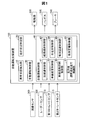
- FIG. 1 is a block diagram illustrating a schematic configuration of an automatic driving support device as an embodiment of the present disclosure.
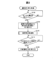
- FIG. 2 is a flowchart showing a processing procedure of switching processing from automatic operation to manual operation.
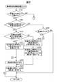
- FIG. 3 is a flowchart showing a detailed processing procedure of the automatic operation processing at the time of abnormality.
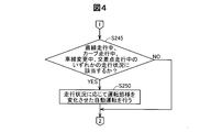
- FIG. 4 is a flowchart showing a detailed processing procedure of the automatic operation processing at the time of abnormality.
- FIG. 5 is a flowchart showing a detailed processing procedure of the determination processing for the presence or absence of abnormality of the sensor in the second embodiment.
- FIG. 1 is a block diagram illustrating a schematic configuration of an automatic driving support device as an embodiment of the present disclosure.
- FIG. 2 is a flowchart showing a processing procedure of switching processing from automatic operation to manual operation.
- FIG. 3 is a flowchart showing a detailed processing procedure of the automatic operation processing at the time of abnormality.
- FIG. 4 is a flowchart showing a detailed processing procedure of the automatic
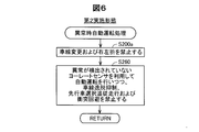
- FIG. 6 is a flowchart showing a detailed processing procedure of the abnormal time automatic operation processing in the second embodiment
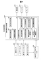
- FIG. 7 is a block diagram showing a schematic configuration of the automatic driving support device in the third embodiment
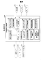
- FIG. 8 is a block diagram illustrating a schematic configuration of the automatic driving support device according to the fourth embodiment.
- the automatic driving support device 100 is configured by an ECU (Electronic Control Unit).
- the automatic driving support apparatus 100 includes a CPU, a ROM, and a RAM (not shown).
- the CPU develops a control program stored in the ROM in advance in the RAM, and executes the control program as the abnormal state detection unit 10, the traveling state identification unit 20, the manual operation control unit 30, and the automatic operation control unit 40. Function.
- the automatic driving support device 100 is electrically connected to the image sensor 300, the radar sensor 305, the first yaw rate sensor 310, the second yaw rate sensor 315, the drive source 200, the handle 205, and the brake 210. ing.
- the image sensor 300 is attached to the inside and outside of the host vehicle and images the situation around the host vehicle.
- the radar sensor 305 is attached to the outside of the vehicle and detects obstacles around the vehicle. For example, a millimeter wave radar corresponds to the radar sensor 305.
- the first yaw rate sensor 310 and the second yaw rate sensor 315 detect the traveling state of the host vehicle.
- the “running state” refers to, for example, a state in which the front direction of the host vehicle is directed leftward with respect to the vehicle front-rear direction, a state in which the host vehicle is accelerating, and It means the state of the vehicle itself during control of automatic driving, such as the current travel position.
- the first yaw rate sensor 310 is used for vehicle posture stabilization control of the host vehicle.
- the first yaw rate sensor 310 detects an angular velocity generated by the yaw motion of the host vehicle.
- the automatic driving control unit 40 described later specifies the posture of the host vehicle using the detection result of the first yaw rate sensor 310, and controls the automatic traveling of the host vehicle based on the posture.
- the second yaw rate sensor 315 is used for detecting the position of the host vehicle.
- the second yaw rate sensor 315 is configured by a gyro sensor.
- the host vehicle position detection unit 50 described later detects the host vehicle position using the detection result of the second yaw rate sensor 315 and the detection result of a vehicle speed sensor (not shown).
- the first yaw rate sensor 310 and the second yaw rate sensor 315 correspond to subordinate concepts of the first sensor in the claims.
- the drive source 200 is mounted on the host vehicle and outputs motive power necessary for driving the host vehicle.
- Examples of the drive source 200 include an engine and a motor.
- the handle 205 is mounted on the host vehicle and is used to control the direction of the host vehicle. Specifically, the steering angle for satisfying the target yaw rate is calculated based on the target yaw rate received from the operation of the handle 205, and the direction of the host vehicle is controlled.
- the brake 210 is mounted on the host vehicle and is used to reduce the vehicle speed and stop braking.
- the abnormal state detection unit 10 detects whether the first yaw rate sensor 310 and the second yaw rate sensor 315 are abnormal. Specifically, the abnormal state detection unit 10 detects that an abnormality has occurred by acquiring an abnormality presence / absence notification output from each of the yaw rate sensors 310 and 315, respectively. Further, the abnormal state detection unit 10 detects the presence / absence of an alternative sensor and the performance of the alternative sensor.
- the traveling state specifying unit 20 specifies the traveling state of the host vehicle.
- the “running situation” means, for example, a situation in which a lane change is going to be performed during a low-speed running at a vehicle speed lower than a predetermined vehicle speed, a left turn, a right turn, This means the situation of the host vehicle during control of automatic driving, such as straight ahead, traveling following the preceding vehicle, tracking the route to the destination, and avoiding collision with the preceding vehicle.
- the traveling state specifying unit 20 specifies the traveling state by using detection results and map information of the image sensor 300, the radar sensor 305, the first yaw rate sensor 310, the second yaw rate sensor 315, and the like.
- the traveling state specifying unit 20 uses the detection result of the image sensor 300 to compare the host vehicle and a target around the host vehicle to detect the relative movement state of the host vehicle, thereby Identify the situation. Specifically, when an image detected when the host vehicle straddles a lane is detected in the captured image of the image sensor 300, the traveling state specifying unit 20 specifies that the host vehicle is changing lanes. May be. For example, when the captured image of the image sensor 300 is repeatedly detected for a predetermined time, and the lane that is on the right side of the host vehicle moves to the left side of the host vehicle with a change in time, the traveling state specifying unit 20 may specify that the host vehicle has changed the lane to the right lane.
- the manual operation control unit 30 controls the own vehicle according to the manual operation by the driver of the own vehicle. Specifically, the manual operation control unit 30 controls the vehicle by controlling various drive mechanisms in accordance with the operation of the handle 205, the accelerator, the brake, and the like by the driver.
- the automatic driving control unit 40 performs automatic driving by controlling automatic driving of the host vehicle. Specifically, the automatic operation control unit 40 controls driving mechanisms such as the engine, the brake 210, and the transmission using the detection results of the sensors 300, 305, 310, and 315.
- the automatic driving control unit 40 includes an acceleration / deceleration control unit 41, a route tracking control unit 42, a lane change control unit 43, a right / left turn control unit 44, a lane departure suppression control unit 45, a collision avoidance control unit 46, A preceding vehicle selection follow-up travel control unit 47 and a collision warning control unit 48 are provided.
- the automatic operation control unit 40 controls two types of automatic operation, normal operation and abnormal operation.
- Normal automatic operation means automatic operation when no abnormality is detected in the first yaw rate sensor 310 and the second yaw rate sensor 315.
- Abnormal automatic operation means automatic operation when an abnormality of the first yaw rate sensor 310 or the second yaw rate sensor 315 is detected.
- the automatic operation control unit 40 automatically detects the abnormality from the normal automatic operation when the abnormality is detected in the first yaw rate sensor 310 or the second yaw rate sensor 315 during the normal automatic operation control. Switch to driving and perform automatic driving.
- the automatic driving is performed by changing the driving mode according to the driving situation specified by the driving condition specifying unit 20.
- the “driving mode” means modes related to various driving operations performed when the vehicle is driven.
- the driving mode relating to the change in the vehicle speed includes increasing the vehicle speed, maintaining the vehicle speed constant, decreasing the vehicle speed, and the like.
- the driving mode related to the lane change corresponds to a state where the lane change is allowed and a state where the lane change is prohibited.
- a driving state related to collision avoidance includes a state where steering for collision avoidance is permitted and a state where steering for collision avoidance is prohibited. Detailed description of the automatic operation at the time of abnormality will be described later.
- the acceleration / deceleration control unit 41 controls the vehicle speed of the host vehicle. Specifically, the acceleration / deceleration control unit 41 uses the detection results of the image sensor 300 and the radar sensor 305 to detect the state of the lane being traveled and the surroundings of the host vehicle, and an accelerator or brake 210 (not shown). Accelerate and decelerate by controlling.
- the route tracking control unit 42 performs control so as to guide the host vehicle to a destination desired by the driver. Specifically, the route tracking control unit 42 guides the host vehicle to the destination by automatically traveling to the destination designated by the driver based on the map information.
- the lane change control unit 43 controls the change of the traveling lane of the host vehicle. Specifically, the lane change control unit 43 uses the detection results of the image sensor 300 and the radar sensor 305 to detect the lanes of the vehicles around the host vehicle and the lane in which the vehicle is traveling, and toward the lane to be changed. By operating the handle 205, the travel lane of the host vehicle is changed.
- the right / left turn control unit 44 controls execution of a right turn or a left turn. Specifically, by using the detection result of the image sensor 300 and map information (not shown) or the like, the shape of the intersection is detected, and the handle 205 is operated along the shape to make a right turn or a left turn.
- the lane departure suppression control unit 45 performs control so as to suppress the departure of the host vehicle from the traveling lane. Specifically, the lane departure suppression control unit 45 suppresses the departure from the traveling lane to another lane by operating the handle 205 so as to maintain the traveling in the traveling lane.
- the collision avoidance control unit 46 performs control so as to avoid collision with the vehicle ahead of the host vehicle and obstacles around the host vehicle. Specifically, the collision avoidance control unit 46 detects the situation around the host vehicle using the detection results of the image sensor 300 and the radar sensor 305, and controls the handle 205 and the brake 210, thereby Avoid collisions with obstacles around your vehicle.
- the preceding vehicle selection follow-up travel control unit 47 performs control so as to follow the preceding vehicle selected by the driver. Specifically, the preceding vehicle selection follow-up travel control unit 47 controls the vehicle speed by controlling the brake 210 and an accelerator (not shown), and performs automatic traveling so that the distance between the preceding vehicle and the preceding vehicle is maintained at a predetermined distance.
- the collision warning control unit 48 warns the driver and the surroundings of the own vehicle when detecting that the own vehicle may collide with an obstacle or the like. Specifically, when it is determined that collision avoidance by the collision avoidance control unit 46 is difficult, the collision alarm control unit 48 issues an alarm by controlling the horn or the like.
- Operation switching process When the user presses a predetermined button provided in the room of the host vehicle, automatic driving at normal time is started. Along with the start of the normal automatic operation, the operation switching process shown in FIG. 2 is started.
- the operation switching process is a case where an abnormality in the first yaw rate sensor 310 or the second yaw rate sensor 315 is detected during the control of the normal time automatic operation, and after switching from the normal time automatic operation to the abnormal time automatic operation, When the condition is satisfied, the process is a process of switching to stop of the own vehicle or manual driving by the driver.
- the abnormal state detection unit 10 determines whether an abnormality (hereinafter simply referred to as “sensor abnormality”) of the first yaw rate sensor 310 or the second yaw rate sensor 315 has been detected (step) S100). Specifically, the abnormal state detection unit 10 acquires an abnormality presence / absence notification from each of the first yaw rate sensor 310 and the second yaw rate sensor 315. When information indicating the presence of abnormality is detected in any of the acquired abnormality presence / absence notifications, it is determined that a sensor abnormality has been detected. On the other hand, when information indicating no abnormality is detected in both of the acquired abnormality presence / absence notifications, it is determined that a sensor abnormality is not detected.
- sensor abnormality hereinafter simply referred to as “sensor abnormality”
- step S100: NO If it is determined that the sensor abnormality is not detected (step S100: NO), the process returns to before step S100, and the normal automatic operation is continued until it is determined that the sensor abnormality is detected. . On the other hand, if it is determined that a sensor abnormality has been detected (step S100: YES), the automatic operation control unit 40 switches from the normal time automatic operation to the abnormal time automatic operation (step S115).
- the traveling state specifying unit 20 determines whether the vehicle is traveling at a low speed or stopped (step S200). Specifically, the traveling state specifying unit 20 acquires the vehicle speed of the host vehicle using a vehicle speed sensor (not shown). And when the vehicle speed of the own vehicle is below a predetermined vehicle speed, it determines with driving
- the predetermined vehicle speed is 15 km / h. The predetermined vehicle speed is not limited to 15 km / h, but may be any value greater than 0 km / h. Further, when the vehicle speed of the host vehicle is 0 km / h for a predetermined period and the engine of the host vehicle is activated, it is determined that the vehicle is stopped.
- the traveling state specifying unit 20 determines whether the vehicle is in a parking prohibited section or an intersection region (step S205).
- the determination as to whether or not the vehicle is in a parking prohibited section or an intersection area is performed using a captured image of the image sensor 300. For example, if a white line indicating a parking prohibited section or a sign indicating a parking prohibited section is detected in the captured image, it is determined that the vehicle is within the parking prohibited section. On the other hand, when the white line which shows the inside of a parking prohibition area, or the sign of a parking prohibition area is not detected, it determines with it not being in a parking prohibition area.
- Whether or not the vehicle is in a parking prohibited section or an intersection area is determined by using map information of a navigation device mounted on the host vehicle or using GPS (Global Positioning System / Global Positioning System). May be.
- the traveling state specifying unit 20 determines whether there is a vehicle with high possibility of collision around the host vehicle (step S210). ). Specifically, the traveling state specifying unit 20 detects a vehicle (another vehicle) around the host vehicle using detection results of the image sensor 300 and the radar sensor 305. If other vehicles are detected around the own vehicle, the vehicle speed of the other vehicle is calculated, and if the own vehicle is temporarily stopped, whether or not there is time for the other vehicle to avoid a collision with the own vehicle. Determine.
- the time for avoiding the collision may be obtained based on, for example, a deceleration assumed in advance, a distance between the host vehicle and the other vehicle, and a relative speed of the other vehicle. If it is determined that there is no time to avoid the collision, it is determined that there is a vehicle with high possibility of collision around the host vehicle. On the other hand, when it is determined that there is time to avoid a collision, it is determined that there is no vehicle with high possibility of collision around the host vehicle.
- the automatic operation control unit 40 travels at a low speed outside the parking prohibited section or outside the intersection area (step S215). Specifically, the automatic operation control unit 40 controls an accelerator and a brake 210 (not shown) to perform automatic traveling while maintaining low speed traveling, and operates the handle 205 to automatically move outside the parking prohibited section or the intersection area. Guide the vehicle.
- the outside of the parking prohibited section is a place different from the inside of the parking prohibited section, and means, for example, a place away from the parking prohibited section by a predetermined distance.
- outside the intersection area is a place different from the inside of the intersection area, and means, for example, a place away from the inside of the intersection area by a predetermined distance.
- step S215 the automatic driving control unit 40 stops the host vehicle (step S220). Specifically, the automatic driving control unit 40 stops (stops) the host vehicle by driving the brake 210. After execution of step S220, the automatic driving control unit 40 notifies the driver that automatic driving has been stopped (step S225). Specifically, the automatic driving control unit 40 displays on the display device (not shown) mounted on the host vehicle a notification display indicating that the automatic driving has been stopped and the vehicle has been stopped (stopped) because a sensor abnormality has been detected. Do. In addition, you may perform an alerting
- step S210 when it is determined in step S210 described above that there is no vehicle with high possibility of collision around the host vehicle (step S210: NO), the automatic operation control unit 40 The own vehicle is stopped in the intersection area (step S230). Specifically, the automatic driving control unit 40 stops (stops) the host vehicle by driving the brake 210 as in step S225 described above. After execution of step S230, the automatic driving control unit 40 notifies the driver that the host vehicle has been stopped in the parking prohibited section or the intersection area (step S235).
- the automatic driving control unit 40 stops the automatic driving because a sensor abnormality is detected on a display device (not shown) mounted on the host vehicle, and within the parking prohibited section or A notification display indicating that the vehicle has been stopped (stopped) in the intersection area is performed.
- step S240 determines whether the vehicle is traveling at a low speed.
- step S240 is executed when it is determined in step S200 that the vehicle is running at a low speed or is stopped. Therefore, the vehicle is running at a low speed or when the vehicle is stopped. In order to identify whether there is any, it is determined whether or not the vehicle is traveling at a low speed.
- the traveling state specifying unit 20 determines whether the vehicle is traveling at a low speed by acquiring the vehicle speed of the host vehicle using a vehicle speed sensor (not shown).
- step S240 it may be determined whether the vehicle is traveling at a low speed based on the detection result acquired in step S200.
- step S240: YES the above-described step S220 is executed, and the automatic operation control unit 40 stops (stops) the host vehicle (step S220).
- step S240: NO the brake 210 is controlled to maintain the stopped state of the host vehicle.
- step S115 shown in FIG. 2 is executed.
- step S200 when it is determined in step S200 described above that the vehicle is not traveling at a low speed or stopped (step S200: NO), as shown in FIG. Then, it is determined whether or not any of the traveling conditions during curve traveling, lane change, or intersection traveling is satisfied (step S245). Specifically, when the steering angle of the handle 205 coincides with the vehicle front direction, it is determined that the vehicle is traveling in a straight line. Further, when the steering angle of the handle 205 is a predetermined angle with respect to the vehicle front-rear direction, or when the detection result of the first yaw rate sensor 310 is a predetermined angular velocity, it is determined that the vehicle is running on a curve.
- the detection result of the image sensor 300 when an image detected when the host vehicle straddles the lane is detected, it is determined that the lane is being changed. If it is determined that the position of the host vehicle is within the intersection area using map information or GPS information, it is determined that the vehicle is traveling at the intersection. Further, when a white line at the intersection is detected in the detection result of the image sensor 300, it is determined that the vehicle is traveling at the intersection.
- step S245 If it is determined that the vehicle travels in a straight line, a curve, a lane change, or an intersection (step S245: YES), the automatic operation control unit 40 changes the driving mode according to the travel.
- the changed automatic operation that is, the abnormal automatic operation is performed (step S250).
- the operation modes shown in the following (A) to (H) are changed compared to before the abnormality of the sensor is detected.
- the acceleration / deceleration control unit 41 performs control so as to decrease the vehicle speed.
- the traveling route cannot be tracked correctly, so that the host vehicle deviates from the traveling route and may collide with an obstacle such as another vehicle. In that case, it is difficult to safely switch to manual operation. For this reason, the vehicle speed is reduced in order to minimize the deviation from the traveling route of the host vehicle.
- the acceleration / deceleration control unit 41 controls the vehicle speed to be prohibited from decreasing when the host vehicle is traveling in the intersection area. This is because if the vehicle is decelerated in the intersection area, it may collide with the following vehicle. For this reason, in order to suppress a reduction in safety, the vehicle speed cannot be reduced when the position of the vehicle is within the intersection area.
- the lane change control unit 43 controls to prohibit a new lane change. If an abnormality is detected in the first yaw rate sensor 310, the vehicle posture of the host vehicle cannot be detected accurately. If the lane change is allowed, dangerous steering is performed, and unexpected vehicle movement occurs. There is a risk of collision with obstacles such as other vehicles. For this reason, a new lane change is prohibited in order to suppress a decrease in safety.
- the lane change control unit 43 controls to prohibit the change of the steering angle of the own vehicle when the own vehicle is changing the lane. If an abnormality is detected in the first yaw rate sensor 310, the vehicle posture of the host vehicle cannot be accurately detected, and the host vehicle may travel in an unexpected direction, possibly colliding with an obstacle such as another vehicle. Because. For this reason, by fixing the rudder angle, the lane change is executed while suppressing a decrease in safety.
- the right / left turn control unit 44 controls to prohibit new right and left turns. If an abnormality is detected in the first yaw rate sensor 310, the vehicle posture of the host vehicle cannot be accurately detected. If the right or left turn is allowed, dangerous steering may occur, and unexpected vehicle movement May occur and may collide with obstacles such as other vehicles. For this reason, in order to suppress the decrease in safety, a new right / left turn is prohibited.
- the collision avoidance control unit 46 performs control so as to prohibit the execution of the brake 210 for avoiding a collision with the preceding vehicle by stopping the operation of the automatic brake. This is because, when an abnormality is detected in the first yaw rate sensor 310, the vehicle posture stabilization control of the host vehicle stops, and therefore, if the automatic brake is activated, there is a possibility of promoting the spin of the vehicle. For this reason, the operation of the automatic brake is stopped in order to suppress a decrease in the stability of the vehicle posture.
- the collision avoidance control unit 46 performs control so as to prohibit new steering for avoiding a collision with the preceding vehicle. Specifically, the collision avoidance control unit 46 continuously executes the steering control being executed, but does not execute a new steering control for avoiding a collision with the preceding vehicle. The steering control during execution is performed based on an accurate vehicle posture detected before the abnormality of the sensor occurs. In contrast, new steering control when an abnormality is detected in the sensor cannot be performed based on an accurate vehicle posture, resulting in dangerous steering and unexpected vehicle movement. May collide with obstacles such as other vehicles. For this reason, in order to suppress a decrease in safety, new steering for avoiding a collision with the preceding vehicle is prohibited.
- the preceding vehicle selection follow-up travel control unit 47 performs control so as to prohibit selection of the preceding vehicle and follow-up travel to the selected preceding vehicle. This is because, when an abnormality is detected in the sensor, there is a possibility that a vehicle traveling in a lane different from the lane in which the host vehicle is traveling may be erroneously selected as a preceding vehicle. Further, by following the erroneously selected preceding vehicle, lane departure or vehicle speed increases, resulting in a decrease in safety. For this reason, in order to suppress a decrease in safety, selection of the preceding vehicle and follow-up traveling to the selected preceding vehicle are prohibited.
- the lane departure suppression control unit 45, the collision warning control unit 48, and the route tracking control unit 42 execute the same processing as in the normal time automatic driving. Since these control units perform processing without using the first yaw rate sensor 310, even if an abnormality is detected in the first yaw rate sensor 310, processing similar to that in normal automatic operation can be performed. It is.
- step S110 After execution of step S250 described above, as shown in FIG. 3, the abnormal time automatic operation processing (step S110) ends, and step S115 shown in FIG. 2 is executed.
- the automatic operation control unit 40 determines whether or not a predetermined time has elapsed (step S115). Specifically, the automatic operation control unit 40 determines whether or not a predetermined time such as 4 seconds, 10 seconds, and 3 minutes has elapsed since the start of the abnormal time automatic operation (step S110). To do. When it is determined that the predetermined time has not elapsed (step S115: NO), the process returns to before execution of step S115, and the automatic operation at the time of abnormality continues until it is determined that the predetermined time has elapsed. Executed. On the other hand, when it is determined that a predetermined time has elapsed (step S115: YES), the automatic operation control unit 40 switches to manual operation (step S120). Note that the predetermined time is not limited to the above-described 4 seconds, 10 seconds, and 3 minutes, and an arbitrary time may be set.
- step S120 When the automatic operation is switched to the manual operation in step S120, the manual operation control unit 30 controls the host vehicle according to the manual operation by the driver. After execution of step S120, the operation switching process ends.
- the automatic driving control unit 40 detects the first yaw rate sensor 310 when an abnormality is detected in the first yaw rate sensor 310 while controlling the automatic driving.
- the automatic operation at the time of abnormality in which the operation mode is changed in accordance with the driving condition specified in comparison with the driving mode before the abnormality of 310 is detected is executed until a predetermined time elapses. After the completion, either the vehicle stop by the automatic operation control unit 40 or the manual operation control by the manual operation control unit 30 is executed, so that the safety of the automatic operation during the period from the automatic operation to the manual operation is switched. The decline in sex can be suppressed.
- the host vehicle when the host vehicle is traveling at a low speed, is traveling in an intersection area or a parking prohibited section, and there is a traveling situation in which there is a vehicle with high possibility of collision around the host vehicle. Since the host vehicle is stopped after moving the vehicle to a place away from the intersection area or a predetermined distance from the parking prohibited section, the host vehicle is stopped in the intersection area or parking prohibited section. Compared with the structure to make it interfere with passage of other vehicles etc., it can suppress. Moreover, it is possible to suppress the occurrence of a collision between the host vehicle and another vehicle in the intersection area or in the parking prohibited section.
- the vehicle when the host vehicle is stopped, the vehicle can be switched to manual operation while maintaining the stopped state of the host vehicle. Therefore, when an abnormality of the first yaw rate sensor 310 is detected during control of automatic driving, It is possible to control the safest vehicle not to run the vehicle, and it is possible to suppress a decrease in the safety of automatic driving during the period from automatic driving to manual driving.
- Second embodiment B1.
- Device configuration Since the automatic driving assistance device 100 in the second embodiment is the same as the automatic driving assistance device 100 in the first embodiment shown in FIG. 1, detailed description thereof is omitted.
- step S100 The operation switching process according to the second embodiment is different from that according to the first embodiment in that the processing content in the determination of whether or not there is an abnormality in the sensor (step S100) is different from the processing content in the abnormal time automatic operation processing (step S110). This is different from the operation switching process in FIG.
- the same steps as those in the first embodiment are denoted by the same reference numerals, and detailed description thereof is omitted.
- the first yaw rate sensor 310 and the first yaw rate sensor 310 and the second yaw rate sensor 315 are used by utilizing the difference between the values indicated by the first yaw rate sensor 310 and the second yaw rate sensor 315.
- the presence / absence of abnormality of the 2-yaw rate sensor 315 is determined.
- the abnormal state detection unit 10 acquires the sensor value of the first yaw rate sensor 310 (step S300). Specifically, the abnormal state detection unit 10 refers to the detection result of a sensor (not shown) attached to the first yaw rate sensor 310 and acquires the value indicated by the first yaw rate sensor 310.
- the abnormal state detection unit 10 acquires an abnormality presence / absence notification of the first yaw rate sensor 310 (step S305). Specifically, an abnormality presence / absence notification output from the first yaw rate sensor 310 is acquired, and information indicating the presence / absence of abnormality is detected.
- the abnormal state detection unit 10 acquires the sensor value of the second yaw rate sensor 315 (step S310).
- step S310 the sensor value indicated by the second yaw rate sensor 315 is acquired in the same procedure as in step S300 described above.
- step S315 the abnormal state detection unit 10 acquires an abnormality presence / absence notification of the second yaw rate sensor 315 (step S315).
- step S315 an abnormality presence / absence notification output from the second yaw rate sensor 315 is acquired and information indicating the presence / absence of abnormality is detected in the same procedure as in step S305 described above.
- the abnormal state detection unit 10 determines whether the first yaw rate sensor 310 and the second yaw rate sensor 315 are abnormal (step S320).
- the abnormal state detection unit 10 calculates the difference between the value indicated by the first yaw rate sensor 310 and the value indicated by the second yaw rate sensor 315. If the calculated difference is greater than or equal to a predetermined threshold, it is determined that an abnormality has been detected in one of the yaw rate sensors. At this time, which yaw rate sensor is abnormal is determined as follows.
- the abnormal state detection unit 10 refers to a map (not shown) in which the difference between the values indicated by the yaw rate sensors 310 and 315 and the failure rate of the yaw rate sensors 310 and 315 are associated with each other, thereby detecting any abnormality of the yaw rate sensor. It is determined whether it is. For example, if the difference between the values indicated by the yaw rate sensors 310 and 315 is large, it is determined that an abnormality has been detected in the yaw rate sensor that is likely to fail.
- step S320 when the difference between the values indicated by the sensors 310 and 315 is equal to or greater than a predetermined threshold value, and information indicating an abnormality is detected in any abnormality presence / absence notification acquired from the sensors 310 and 315, It is determined that an abnormality has been detected in the sensor. On the other hand, when the difference between the values indicated by the sensors 310 and 315 is smaller than a predetermined threshold, or when information indicating no abnormality is detected in both of the abnormality presence / absence notifications acquired from the sensors 310 and 315, there is an abnormality in the sensor. It is determined that it has not been detected.
- the abnormal state automatic operation processing in the second embodiment shown in FIG. 6 is executed by executing step S200a instead of step S200, omitting steps S205 to S250, and adding step S260. This is different from the automatic operation process at the time of abnormality in the first embodiment shown in FIG. 3 and FIG.
- the same steps as those in the first embodiment are denoted by the same reference numerals, and detailed description thereof is omitted.
- automatic operation is performed using a yaw rate sensor in which no abnormality is detected. At this time, it controls so that a predetermined driving
- the automatic operation control unit 40 prohibits lane change and right / left turn (step S200a). This is because when the abnormality of the first yaw rate sensor 310 is detected, it is difficult to control the vehicle stability of the host vehicle as compared with the normal automatic driving, and therefore it is possible to execute lane change and right / left turn. Control to not.
- step S260 the automatic operation control unit 40 prohibits lane departure suppression, preceding selection follow-up traveling, and collision avoidance while performing automatic operation using a yaw rate sensor in which no abnormality is detected. For example, when an abnormality of the first yaw rate sensor 310 is detected, the automatic operation control unit 40 performs automatic operation at the time of abnormality using the second yaw rate sensor 315 in which no abnormality is detected until switching to manual operation. Do. In addition, the automatic driving control unit 40 performs control so that lane departure suppression, preceding selection follow-up traveling, and collision avoidance cannot be performed.
- step S115 shown in FIG. 2 is executed.
- the automatic driving support device 100 of the second embodiment described above has the same effects as the automatic driving support device 100 of the first embodiment.
- the presence / absence of abnormality of the first yaw rate sensor 310 or the second yaw rate sensor 315 is detected based on the difference between the value indicated by the first yaw rate sensor 310 and the value indicated by the second yaw rate sensor 315, the yaw rate sensor Abnormality can be easily detected.
- the lane change and the right / left turn which are greatly affected by the decrease in the stability of the vehicle posture when the abnormality of the first yaw rate sensor 310 is detected are prohibited at an early timing after the detection of the abnormality of the sensor. Compared with the case where the lane change and the left / right turn are continuously allowed when the abnormality is detected, it is possible to suppress a decrease in safety.
- the influence of the abnormality of the first yaw rate sensor 310 is relatively small, and prohibition of lane departure suppression, advancer selection follow-up running, and collision avoidance are prohibited, so no abnormality is detected.
- an executable function can be provided to the user for as long as possible, and a decrease in convenience for the user can be suppressed.
- the automatic driving assistance device 100a in the third embodiment shown in FIG. 7 is not directly connected to the second yaw rate sensor 315, but indirectly connected to the second yaw rate sensor ECU 320. It differs from the automatic driving assistance apparatus 100 in the first embodiment shown in FIG. Since the other configuration of the automatic driving support device 100a in the third embodiment is the same as that of the automatic driving support device 100 in the first embodiment, the same components are denoted by the same reference numerals, and detailed description thereof is omitted. To do.
- the second yaw rate sensor ECU 320 controls the second yaw rate sensor 315.
- the second yaw rate sensor 315 is configured separately.
- the second yaw rate sensor 315 is disposed in the vicinity of the center of gravity position of the vehicle.
- “near the position of the center of gravity of the vehicle” means, for example, a position within a range of 50 cm from the position of the center of gravity of the vehicle. In addition, it is not restricted to 50 cm, For example, you may set another arbitrary value in consideration of the magnitude
- the second yaw rate sensor 315 is not limited to the vicinity of the center of gravity of the vehicle, and may be disposed in the vicinity of the first yaw rate sensor 310.
- operation switching process in the third embodiment is the same as the operation switching process in the first embodiment or the second embodiment, and a detailed description thereof will be omitted.
- the automatic driving support device 100a of the third embodiment described above has the same effects as the above embodiments.
- the second yaw rate sensor 315 is disposed at a position close to the center of gravity of the vehicle, the yaw rate is more accurate than the configuration in which the second yaw rate sensor 315 is disposed away from the position of the center of gravity of the vehicle. Can measure well. Further, in the configuration in which the second yaw rate sensor 315 is disposed in the vicinity of the first yaw rate sensor 310, it is possible to reduce the time required to determine whether the sensor is abnormal or to switch the sensor when a sensor abnormality is detected.
- the automatic driving support device 100b in the fourth embodiment shown in FIG. 8 includes the second yaw rate sensor 315 and functions as the own vehicle position detection unit 50 in the automatic driving in the first embodiment shown in FIG. Different from the support device 100. Since the other configuration of the automatic driving support device 100b in the fourth embodiment is the same as that of the automatic driving support device 100 in the first embodiment, the same components are denoted by the same reference numerals, and detailed description thereof is omitted. To do.
- the second yaw rate sensor 315 is different from the first embodiment and the second embodiment in that the second yaw rate sensor 315 is configured as one functional unit of the automatic driving support device 100b, and the specific functions are the first embodiment and the second embodiment. This is the same as the second yaw rate sensor 315 of the embodiment.
- the host vehicle position detection unit 50 detects the position of the host vehicle using the detection result of the second yaw rate sensor 315.
- the automatic driving support apparatus 100b of the fourth embodiment described above has the same effects as those of the above embodiments.
- the automatic driving support device 100b, the second yaw rate sensor 315, and the own vehicle position detection unit 50 can be integrated, the second yaw rate sensor 315 and the own vehicle position detection unit 50 are included in the automatic driving support device 100b.
- CPU and memory can be used, and cost can be reduced.
- Modification 2 In the automatic operation at the time of abnormality in the first embodiment, the operation mode is changed for all of the above (A) to (H), but the present disclosure is not limited to this. For example, you may perform only said (A). Further, for example, the above (C) and (E) may be performed. That is, in general, any configuration that changes at least one of the operation modes (A) to (H) has the same effect as the first embodiment.
- the right / left turn control unit 44 prohibits new right and left turns, but the present disclosure is not limited thereto. For example, you may bend in the direction which the handle 205 of the own vehicle faces. In addition, for example, when the host vehicle is traveling in an intersection area and the traveling lane of the host vehicle can go straight and the steering wheel 205 of the host vehicle faces a straight ahead direction, the host vehicle may travel straight. For example, you may move to safe places, such as a road shoulder. Even in such a configuration, the same effects as those of the first embodiment can be obtained.
- the lane change control unit 43 prohibits a new lane change, but the present disclosure is not limited to this.
- the execution of the lane change may be stopped and the vehicle may remain in the lane before the lane change.
- the vehicle may travel on a white line that the host vehicle is going to straddle, or may travel while maintaining a constant distance from the white line.
- the driver's front gaze point specified by the function unit is inside the traveling lane.
- the lane change need not be executed.
- the lane change may be executed.
- the rudder angle may be fixed or the rudder angle may not be fixed. Even in such a configuration, the same effects as those of the first embodiment can be obtained.
- the collision avoidance control unit 46 stops the operation of the automatic brake, but the present disclosure is not limited to this.
- the automatic braking operation may be continued when it is determined that the vehicle attitude is estimated from an alternative sensor of the first yaw rate sensor 310 and a steering angle sensor (not shown), and the vehicle attitude is stable. Even in such a configuration, the same effects as those of the first embodiment can be obtained.
- the manual operation is switched to when it is determined that a predetermined time has elapsed, but the present disclosure is not limited to this.
- manual operation may be switched to when manual operation start instruction is detected by the driver.
- an operation indicating that the driver is ready for manual driving such as an operation of the driver stepping on the brake 210 or an accelerator (not shown) or an operation of pressing a predetermined button in the passenger compartment, has been detected. It may be switched to manual operation at the opportunity. Even in such a configuration, the same effects as those of the above embodiments can be obtained.
- the automatic operation at the time of abnormality is performed using the second yaw rate sensor 315 in which no abnormality is detected, but the present disclosure is not limited to this.
- the normal automatic operation may be performed using a sensor other than the second yaw rate sensor 315 (such as a steering angle sensor or a vehicle speed sensor).
- the first yaw rate sensor 310 when the automatic driving performance is reduced by using the second yaw rate sensor 315, the steering angle sensor, the vehicle speed sensor, and the like, the first implementation is performed.
- the driving situation may be specified, and the driving mode may be changed according to the specified driving situation. Even in such a configuration, the same effects as those of the second embodiment can be obtained.
- the notification display to the driver is displayed on a display device (not shown), but the present disclosure is not limited to this.
- an alarm sound may be output for notification. Even in such a configuration, the same effects as those of the above embodiments can be obtained.
- the route tracking control unit 42 controls the route tracking based on the map information, but the present disclosure is not limited to this.
- the path tracking may be performed using an alternative sensor different from the yaw rate sensors 310 and 315.
- the target tracking angle may be determined and the route tracking may be performed.
- the target tracking angle may be determined by performing the steering angle control without using the yaw rate, and the route tracking may be performed.
- you may switch from feedback control to feedforward control. Even in such a configuration, the same effects as those of the above embodiments can be obtained.
- Modification 11 In Modification Example 10, when a sensor having a sample period different from that of each yaw rate sensor 310 and 315 is used as an alternative sensor for each yaw rate sensor 310 and 315, the control gain may be changed in accordance with the sample period. For example, when changing from a yaw rate sensor 310 or 315 with a fast sample period to a substitute sensor with a slow sample period, the value detected by the substitute sensor changes (roughly), so the difference from the target value becomes large. It becomes easy to deviate from the route. In this case, the stability of the path tracking control characteristic is lowered. For this reason, by reducing the control gain by reducing the control response, it is possible to suppress a decrease in the stability of the control characteristics of the path tracking. Even in such a configuration, the same effects as those of Modification 10 are obtained.
- control is performed to prohibit the lane change and the right / left turn when the abnormality of the first yaw rate sensor 310 is detected, but the present disclosure is not limited to this.
- control may be performed to allow lane change, right / left turn, and the like. Even in such a configuration, the same effects as those of the second embodiment can be obtained.
- the vehicle speed is not reduced when the position of the host vehicle is in the intersection area, but the present disclosure is not limited to this.
- the vehicle speed may be reduced.
- the vehicle speed may be reduced by reducing the degree of vehicle speed reduction. Even in such a configuration, the same effects as those of the first embodiment can be obtained.
- step S205 and step S240 were performed, the stop state of the own vehicle was maintained, but this indication is not limited to this.
- Modification 15 In each embodiment and each modification, some or all of the functions and processes realized by software may be realized by hardware. In addition, some or all of the functions and processes realized by hardware may be realized by software. As the hardware, for example, various circuits such as an integrated circuit, a discrete circuit, or a circuit module obtained by combining these circuits may be used. In addition, when some or all of the functions of the present disclosure are realized by software, the software (computer program) can be provided in a form stored in a computer-readable recording medium.
- Computer-readable recording medium is not limited to a portable recording medium such as a flexible disk or CD-ROM, but is also fixed to an internal storage device in a computer such as various types of RAM and ROM, or a computer such as a hard disk. It also includes an external storage device. That is, the “computer-readable recording medium” has a broad meaning including an arbitrary recording medium capable of fixing a data packet instead of temporarily.
Landscapes
- Engineering & Computer Science (AREA)
- Automation & Control Theory (AREA)
- Mechanical Engineering (AREA)
- Transportation (AREA)
- Human Computer Interaction (AREA)
- Physics & Mathematics (AREA)
- General Physics & Mathematics (AREA)
- Radar, Positioning & Navigation (AREA)
- Aviation & Aerospace Engineering (AREA)
- Remote Sensing (AREA)
- Business, Economics & Management (AREA)
- Health & Medical Sciences (AREA)
- Artificial Intelligence (AREA)
- Evolutionary Computation (AREA)
- Game Theory and Decision Science (AREA)
- Medical Informatics (AREA)
- Traffic Control Systems (AREA)
- Control Of Driving Devices And Active Controlling Of Vehicle (AREA)
Abstract
自動運転支援装置(100)は、運転者の手動運転に応じて車両を制御する手動運転制御部(30)と、車両の走行状態又は車両の周囲の状況を検出する第1センサ(310、315)の検出結果を利用して、自動運転を制御する自動運転制御部(40)と、第1センサの異常有無を検出する異常状態検出部(10)と、走行状況を特定する走行状況特定部(20)と、を備える。自動運転制御部は、自動運転を制御中に第1センサの異常が検出された場合に、特定された走行状況に応じて運転態様を変化させた異常時自動運転を、予め定められた条件が満たされるまで実行し、異常時自動運転の終了後に、自動運転制御部による車両の停止と、手動運転制御部による手動運転の制御と、のいずれかが実行される。
Description
本出願は、2017年5月16日に出願された日本出願番号2017-96910号に基づくもので、ここにその記載内容を援用する。
本開示は、自動運転支援装置に関する。
従来、車両に搭載されたセンサ等の検出結果を利用して車両を自動走行させる自動運転支援装置が知られている。特許文献1には、センサ等に異常が生じて車両の走行が困難である場合に、自動走行を継続させる自動運転支援装置が開示されている。
しかしながら、特許文献1の記載の技術では、センサ等に異常が生じて車両の走行が困難であるにもかかわらず、自車両の周囲の状況および自車両の走行状態等を考慮することなく車両の自動運転を継続させるため、安全性が低下するという問題が生じ得る。また、センサ等に異常が生じて自動運転から運転者による手動運転に切り替える場合であっても、自動運転から手動運転に切り替えるまでの間の安全性が低下するという問題が生じ得る。そこで、自動運転支援装置において、自動運転から手動運転へ切り替えるまでの間における自動運転の安全性の低下を抑制する技術が望まれている。
本開示は、上述の課題の少なくとも一部を解決するためになされたものであり、以下の形態として実現することが可能である。
本開示の一実施形態によれば、車両に搭載されて用いられる自動運転支援装置が提供される。この自動運転支援装置は、前記車両の運転者による手動運転に応じて前記車両を制御する手動運転制御部と;前記車両の走行状態または前記車両の周囲の状況を検出する第1センサの検出結果を利用して、前記車両の自動運転を制御する自動運転制御部と;前記第1センサの異常有無を検出する異常状態検出部と;前記車両の走行状況を特定する走行状況特定部と;を備え;前記自動運転制御部は、前記車両の自動運転を制御中に前記第1センサの異常が検出された場合に、前記第1センサの異常が検出される前と比べて特定された前記走行状況に応じて運転態様を変化させた前記自動運転である異常時自動運転を、予め定められた条件が満たされるまで実行し;前記異常時自動運転の終了後に、前記自動運転制御部による前記車両の停止と、前記手動運転制御部による前記手動運転の制御と、のいずれかが実行される。
この形態の自動運転支援装置によれば、自動運転制御部は、自動運転を制御中に第1センサの異常が検出された場合に、第1センサの異常が検出される前の運転態様と比べて特定された走行状況に応じて運転態様を変化させた異常時自動運転を予め定められた条件が満たされるまで実行し、異常時自動運転の終了後に、自動運転制御部による車両の停止と、手動運転制御部による手動運転の制御と、のいずれかが実行されるので、自動運転から手動運転へ切り替えるまでの間における自動運転の安全性の低下を抑制できる。
本開示は、種々の形態で実現することも可能である。例えば、車両の自動運転支援方法、自動運転支援装置を搭載した車両、また、これらの装置や方法を実現するためのコンピュータプログラム等の形態で実現できる。
本開示についての上記目的およびその他の目的、特徴や利点は、添付の図面を参照しながら下記の詳細な記述により、より明確になる。その図面は、
図1は、本開示の一実施形態としての自動運転支援装置の概略構成を示すブロック図であり、
図2は、自動運転から手動運転への切り替え処理の処理手順を示すフローチャートであり、
図3は、異常時自動運転処理の詳細な処理手順を示すフローチャートであり、
図4は、異常時自動運転処理の詳細な処理手順を示すフローチャートであり、
図5は、第2実施形態におけるセンサの異常有無の判定処理の詳細な処理手順を示すフローチャートであり、
図6は、第2実施形態における異常時自動運転処理の詳細な処理手順を示すフローチャートであり、
図7は、第3実施形態における自動運転支援装置の概略構成を示すブロック図であり、
図8は、第4実施形態における自動運転支援装置の概略構成を示すブロック図である。
A.第1実施形態:
A1.装置構成:
図1に示す第1実施形態における自動運転支援装置100は、図示しない車両に搭載され、車両に取り付けられたセンサ等の検出結果を利用して自車両の自動走行を制御して自動運転を実行させる。本実施形態において、自動運転支援装置100は、ECU(Electronic Control Unit)により構成されている。自動運転支援装置100は、図示しないCPU、ROMおよびRAMを有する。かかるCPUがROMに予め記憶されている制御プログラムをRAMに展開して実行することにより、異常状態検出部10と、走行状況特定部20と、手動運転制御部30と、自動運転制御部40として機能する。また、自動運転支援装置100は、画像センサ300と、レーダーセンサ305と、第1ヨーレートセンサ310と、第2ヨーレートセンサ315と、駆動源200と、ハンドル205と、ブレーキ210と電気的に接続されている。
画像センサ300は、自車両の車室内および車室外に取り付けられており、自車両の周囲の状況を撮像する。レーダーセンサ305は、自車両の室外に取り付けられており、車両の周囲の障害物等を検出する。レーダーセンサ305としては、例えば、ミリ波レーダが該当する。
第1ヨーレートセンサ310および第2ヨーレートセンサ315は、自車両の走行状態を検出する。本実施形態において、「走行状態」とは、例えば、自車両の前方方向が車両前後方向に対して左方向を向いているとの状態、自車両が加速中であるとの状態および自車両の現在の走行位置等、自動運転を制御中における自車両自体の状態を意味する。
第1ヨーレートセンサ310は、自車両の車両姿勢安定化制御に用いられる。第1ヨーレートセンサ310は、自車両のヨー運動によって発生する角速度を検出する。後述の自動運転制御部40は、第1ヨーレートセンサ310の検出結果を利用して自車両の姿勢を特定し、かかる姿勢に基づき自車両の自動走行を制御する。
第2ヨーレートセンサ315は、自車両の位置検出に用いられる。第2ヨーレートセンサ315は、一例として、ジャイロセンサにより構成されている。後述の自車両位置検出部50は、第2ヨーレートセンサ315の検出結果および図示しない車速センサの検出結果を利用して自車両位置を検出する。本実施形態において、第1ヨーレートセンサ310および第2ヨーレートセンサ315は、請求項における第1センサの下位概念に相当する。
駆動源200は、自車両に搭載されており、自車両の走行に必要な動力を出力する。駆動源200としては、例えば、エンジンやモーターが該当する。ハンドル205は、自車両に搭載されており、自車両の向きを制御するために用いられる。具体的には、ハンドル205の操作から受け付けた目標ヨーレートに基づいて、目標ヨーレートを満たすための舵角を算出して自車両の向きを制御する。ブレーキ210は、自車両に搭載されており、車速の減速、制動停止に用いられる。
異常状態検出部10は、第1ヨーレートセンサ310および第2ヨーレートセンサ315の異常有無を検出する。具体的には、異常状態検出部10は、各ヨーレートセンサ310、315からそれぞれ出力される異常有無通知を取得することにより、異常が生じたことを検出する。また、異常状態検出部10は、代替センサの有無や、代替センサの性能を検出する。
走行状況特定部20は、自車両の走行状況を特定する。本実施形態において、「走行状況」とは、例えば、停車中、予め定められた車速よりも低い車速での低速走行中、これから車線変更を行おうとしている状況、左折中、右折中、交差点を直進中、前方車両に追従して走行中、目的地までの経路追跡中および前方車両との衝突回避運転中等、自動運転を制御中における自車両の状況を意味する。走行状況特定部20は、画像センサ300、レーダーセンサ305、第1ヨーレートセンサ310および第2ヨーレートセンサ315等の検出結果および地図情報等を利用して、走行状況を特定する。例えば、走行状況特定部20は、画像センサ300の検出結果を利用して、自車両と自車両の周囲の物標とを比較して自車両の相対的な移動状態を検出することにより、走行状況を特定する。具体的には、画像センサ300の撮像画像において、自車両が車線を跨いだ場合に検出される画像が検出された場合、走行状況特定部20は、自車両が車線変更中であると特定してもよい。例えば、画像センサ300の撮像画像を所定時間の間繰り返し検出して、自車両の右側にあった車線が、時間の変化に伴って、自車両の左側へ移動していく場合、走行状況特定部20は、自車両が右車線へ車線変更を行ったと特定してもよい。
手動運転制御部30は、自車両の運転者による手動運転に応じて自車両を制御する。具体的には、手動運転制御部30は、運転者によるハンドル205、アクセルおよびブレーキ等の操作に応じて各種駆動機構を制御することにより車両を制御する。
自動運転制御部40は、自車両の自動走行を制御して自動運転を行う。具体的には、自動運転制御部40は、各センサ300、305、310および315の検出結果を利用して、エンジン、ブレーキ210およびトランスミッション等の駆動機構を制御する。
自動運転制御部40は、加減速制御部41と、経路追跡制御部42と、車線変更制御部43と、右左折制御部44と、車線逸脱抑制制御部45と、衝突回避制御部46と、先行車選択追従走行制御部47と、衝突警報制御部48とを有する。
本実施形態において、自動運転制御部40は、通常時自動運転と、異常時自動運転との2種類の自動運転を制御する。「通常時自動運転」とは、第1ヨーレートセンサ310および第2ヨーレートセンサ315の異常が検出されていない場合における自動運転を意味する。「異常時自動運転」とは、第1ヨーレートセンサ310または第2ヨーレートセンサ315の異常を検出した場合における自動運転を意味する。自動運転制御部40は、後述の自動運転支援処理において、通常時自動運転を制御中に第1ヨーレートセンサ310または第2ヨーレートセンサ315の異常を検出した場合に、通常時自動運転から異常時自動運転に切り替えて自動運転を行う。
異常時自動運転では、走行状況特定部20により特定された走行状況に応じて運転態様を変化させた自動運転を行う。本実施形態において、「運転態様」とは、車両を走行させる際に行われる種々の運転操作に関する態様を意味する。例えば、車速の変更に関する運転態様としては、車速を増加させること、車速を一定に維持することおよび車速を減少させること等が該当する。また、例えば、車線変更に関する運転態様としては、車線変更を許容する状態および車線変更を禁止する状態等が該当する。また、例えば、衝突回避に関する運転態様としては、衝突回避のための操舵を許容する状態および衝突回避のための操舵を禁止する状態等が該当する。異常時自動運転についての詳細な説明は、後述する。
加減速制御部41は、自車両の車速を制御する。具体的には、加減速制御部41は、画像センサ300およびレーダーセンサ305の検出結果を利用して、走行中のレーンの状況や自車両の周囲の状況を検出し、図示しないアクセルやブレーキ210を制御することにより加速や減速を行う。
経路追跡制御部42は、運転者の所望する目的地まで自車両を誘導するように制御する。具体的には、経路追跡制御部42は、地図情報に基づいて、運転者により指定された目的地までの自動走行を行うことにより、自車両を目的地まで誘導する。
車線変更制御部43は、自車両の走行車線の変更を制御する。具体的には、車線変更制御部43は、画像センサ300およびレーダーセンサ305の検出結果を利用して、自車両の周囲の車両や走行中のレーンの車線を検出し、変更先の車線に向けてハンドル205を操作することにより、自車両の走行車線の変更を行う。
右左折制御部44は、右折または左折の実行を制御する。具体的には、画像センサ300の検出結果および図示しない地図情報等を利用して、交差点の形状を検出し、かかる形状に沿ってハンドル205を操作することにより、右折または左折を行う。
車線逸脱抑制制御部45は、自車両の走行車線からの逸脱を抑制するように制御する。具体的には、車線逸脱抑制制御部45は、走行中のレーンでの走行を維持するようにハンドル205を操作することにより、走行中のレーンから他のレーンに逸脱することを抑制する。
衝突回避制御部46は、自車両の前方車両および自車両の周囲の障害物等との衝突を回避するように制御する。具体的には、衝突回避制御部46は、画像センサ300およびレーダーセンサ305の検出結果を利用して自車両の周囲の状況を検出し、ハンドル205およびブレーキ210を制御することにより、前方車両や自車両の周囲の障害物等との衝突を回避する。
先行車選択追従走行制御部47は、運転者により選択された先行車に追従して走行するように制御する。具体的には、先行車選択追従走行制御部47は、ブレーキ210および図示しないアクセルを制御することにより車速を制御して、先行車との車間距離を所定距離に保つように自動走行を行う。
衝突警報制御部48は、自車両が障害物等と衝突する可能性があることを検出した場合に、運転者および自車両の周囲に対して警報を行う。具体的には、衝突警報制御部48は、衝突回避制御部46による衝突回避が困難であると判定された場合に、クラクション等を制御することにより警報を行う。
A2.運転切り替え処理:
ユーザーが自車両の室内に設けられた所定のボタンを押下すると、通常時自動運転が開始される。この通常時自動運転の開始とともに、図2に示す運転切り替え処理が開始される。運転切り替え処理とは、通常時自動運転を制御中に第1ヨーレートセンサ310または第2ヨーレートセンサ315の異常が検出された場合に、通常時自動運転から異常時自動運転に切り替えた後、所定の条件が満たされると、自車両の停止、または、運転者による手動運転に切り替える処理である。
ユーザーが自車両の室内に設けられた所定のボタンを押下すると、通常時自動運転が開始される。この通常時自動運転の開始とともに、図2に示す運転切り替え処理が開始される。運転切り替え処理とは、通常時自動運転を制御中に第1ヨーレートセンサ310または第2ヨーレートセンサ315の異常が検出された場合に、通常時自動運転から異常時自動運転に切り替えた後、所定の条件が満たされると、自車両の停止、または、運転者による手動運転に切り替える処理である。
図2に示すように、異常状態検出部10は、第1ヨーレートセンサ310または第2ヨーレートセンサ315の異常(以下、単に「センサの異常」と呼ぶ)を検出したか否かを判定する(ステップS100)。具体的には、異常状態検出部10は、第1ヨーレートセンサ310および第2ヨーレートセンサ315のそれぞれから異常有無通知を取得する。取得したいずれかの異常有無通知において異常ありを示す情報を検出した場合、センサの異常を検出したと判定する。これに対して、取得した両方の異常有無通知において異常なしを示す情報を検出した場合、センサの異常を検出していないと判定する。センサの異常を検出していないと判定されると(ステップS100:NO)、ステップS100の実行前に戻り、センサの異常を検出したと判定されるまで通常時自動運転が継続して実行される。他方、センサの異常を検出したと判定されると(ステップS100:YES)、自動運転制御部40は、通常時自動運転から異常時自動運転に切り替える(ステップS115)。
図3に示す異常時自動運転処理が開始されると、走行状況特定部20は、低速走行中または停車中であるか否かを判定する(ステップS200)。具体的には、走行状況特定部20は、図示しない車速センサを利用して自車両の車速を取得する。そして、自車両の車速が所定の車速以下である場合、低速走行中であると判定する。本実施形態において、所定の車速は、時速15kmである。なお、所定の車速は、時速15kmに限らず、時速0kmよりも大きな任意の値としてもよい。また、自車両の車速が所定期間時速0kmであり、かつ、自車両のエンジンが起動している場合、停車中であると判定する。
低速走行中または停車中であると判定された場合(ステップS200:YES)、走行状況特定部20は、駐車禁止区間内または交差点領域内であるか否かを判定する(ステップS205)。本実施形態では、駐車禁止区間内または交差点領域内であるか否かの判定は、画像センサ300の撮像画像を利用して行われる。例えば、撮像画像において、駐車禁止区間を示す白線や、駐車禁止区間の標識が検出された場合、駐車禁止区間内であると判定する。これに対して、駐車禁止区間内を示す白線や、駐車禁止区間の標識が検出されない場合、駐車禁止区間内ではないと判定する。また、例えば、撮像画像において、信号機、停止線、横断歩道の白線が検出された場合、交差点領域内であると判定する。これに対して、信号機、停止線、横断歩道の白線が検出されない場合、交差点領域内ではないと判定する。なお、駐車禁止区間内または交差点領域内であるか否かの判定は、自車両に搭載されたナビゲーション装置の地図情報や、GPS(Global Positioning System/全地球測位システム)を利用することにより判定してもよい。
駐車禁止区間内または交差点領域内であると判定された場合(ステップS205:YES)、走行状況特定部20は、自車両の周囲に衝突可能性の高い車両がいるか否かを判定する(ステップS210)。具体的には、走行状況特定部20は、画像センサ300およびレーダーセンサ305の検出結果を利用して、自車両の周囲の車両(他車両)を検出する。そして、自車両の周囲に他車両が検出された場合に、その他車両の車速を算出し、仮に自車両を停止させた場合にその他車両が自車両への衝突を回避する時間があるか否かを判定する。衝突を回避する時間は、例えば、予め想定される減速度と、自車両と他車両との間の距離と、他車両の相対的速度とに基づいて求めてもよい。衝突を回避する時間がないと判定された場合、自車両の周囲に衝突可能性の高い車両がいると判定する。これに対して、衝突を回避する時間があると判定された場合、自車両の周囲に衝突可能性の高い車両がいないと判定する。
自車両の周囲に衝突可能性の高い車両がいると判定された場合(ステップS210:YES)、自動運転制御部40は、駐車禁止区間外または交差点領域外まで低速走行する(ステップS215)。具体的には、自動運転制御部40は、図示しないアクセルとブレーキ210を制御して低速走行を維持しつつ自動走行を行うとともに、ハンドル205を操作して駐車禁止区間外または交差点領域外に自車両を誘導する。なお、駐車禁止区間外は、駐車禁止区間内とは異なる場所であり、例えば、駐車禁止区間内から所定距離離れた場所を意味する。また、交差点領域外は、交差点領域内とは異なる場所であり、例えば、交差点領域内から所定距離離れた場所を意味する。
ステップS215の実行後、自動運転制御部40は、自車両を停止させる(ステップS220)。具体的には、自動運転制御部40は、ブレーキ210を駆動させることにより、自車両を停止(停車)させる。ステップS220の実行後、自動運転制御部40は、自動運転を停止した旨を運転者に報知する(ステップS225)。具体的には、自動運転制御部40は、自車両に搭載された図示しない表示装置に、センサの異常を検出したために自動運転を停止して車両を停止(停車)させた旨の報知表示を行う。なお、報知表示は、自車両に搭載されたナビゲーション装置の有する表示部に行ってもよい。ステップS225の実行後、異常時自動運転処理が終了し、図2に示すステップS115が実行される。
図3に示すように、上述のステップS210において、自車両の周囲に衝突可能性の高い車両がいないと判定された場合(ステップS210:NO)、自動運転制御部40は、駐車禁止区間内または交差点領域内に自車両を停止させる(ステップS230)。具体的には、自動運転制御部40は、上述のステップS225と同様に、ブレーキ210を駆動させることにより、自車両を停止(停車)させる。ステップS230の実行後、自動運転制御部40は、駐車禁止区間内または交差点領域内に自車両を停止させた旨を運転者に報知する(ステップS235)。具体的には、自動運転制御部40は、上述のステップS225と同様に、自車両に搭載された図示しない表示装置に、センサの異常を検出したために自動運転を停止して駐車禁止区間内または交差点領域内に車両を停止(停車)させた旨の報知表示を行う。
上述のステップS205において、駐車禁止区間内または交差点領域内ではないと判定された場合(ステップS205:NO)、走行状況特定部20は、低速走行中であるか否かを判定する(ステップS240)。ステップS240が実行されるのは、ステップS200において低速走行中または停車中であると判定された場合であるので、低速走行中である場合と、停車中である場合とのうちのいずれの場合であるかを識別するために、低速走行中であるか否かを判定する。走行状況特定部20は、上述のステップS200と同様に、図示しない車速センサを利用して自車両の車速を取得することにより、低速走行中であるか否かを判定する。なお、ステップS200で取得した検出結果により、低速走行中であるか否かを判定してもよい。低速走行中であると判定された場合(ステップS240:YES)、上述のステップS220が実行されて、自動運転制御部40は、自車両を停止(停車)させる(ステップS220)。他方、低速走行中でない、すなわち停車中であると判定されると(ステップS240:NO)、ブレーキ210を制御して自車両の停車状態を維持する。その後、上述のステップS225実行後と同様に、異常時自動運転処理が終了して図2に示すステップS115が実行される。
図3に示すように、上述のステップS200において、低速走行中または停車中ではないと判定された場合(ステップS200:NO)、図4に示すように、走行状況特定部20は、直線走行中、カーブ走行中、車線変更中、交差点走行中のいずれかの走行状況に該当するか否かを判定する(ステップS245)。具体的には、ハンドル205の操舵角が車両前方方向と一致する場合、直線走行中であると判定する。また、ハンドル205の操舵角が車両前後方向に対して所定の角度である場合や、第1ヨーレートセンサ310の検出結果が所定の角速度である場合、カーブ走行中であると判定する。また、画像センサ300の検出結果において、自車両が車線を跨いだ場合に検出される画像が検出された場合、車線変更中であると判定する。また、地図情報やGPS情報を利用して自車両の位置が交差点領域内であると判定された場合、交差点走行中であると判定する。また、画像センサ300の検出結果において、交差点の白線が検出された場合、交差点走行中であると判定する。
直線走行中、カーブ走行中、車線変更中、交差点走行中のいずれかの走行状況に該当すると判定された場合(ステップS245:YES)、自動運転制御部40は、走行状況に応じて運転態様を変化させた自動運転、すなわち異常時自動運転を行う(ステップS250)。
本実施形態において、異常時自動運転では、センサの異常が検出される前と比べて、以下の(A)~(H)に示す運転態様の変化が行われている。
(A)自車両の車速を減少させること
(B)自車両の位置が交差点領域内である場合に、自車両の車速を減少可能から減少不可にすること
(C)新たな車線変更を許容する状態から禁止する状態に変更すること
(D)特定された走行状況が車線変更中である場合に、自車両の舵角の変更を許容する状態から禁止する状態に変更すること
(E)新たな右左折を許容する状態から禁止する状態に変更すること
(F)前方車両との衝突回避のための自車両のブレーキの実行を許容する状態から禁止する状態に変更すること
(G)前方車両との衝突回避のための自車両の操舵を新たに許容する状態から禁止する状態に変更すること
(H)前方車両に対する追従走行を許容する状態から禁止する状態に変更すること
上記(A)~(H)について以下詳細を説明する。
上記(A)に関し、加減速制御部41は、車速を減少させるように制御する。ヨーレートセンサ310、315に異常が検出された場合、走行中の経路を正しく追跡できないために自車両が走行中の経路から逸脱してしまい、他車両等の障害物と衝突するおそれがある。その場合、安全に手動運転へ切り替えることが困難である。このため、自車両の走行中の経路からの逸脱を最小限にするために、車速を減少させる。
上記(B)に関し、加減速制御部41は、自車両が交差点領域内を走行中である場合、車速の減少を禁止するように制御する。交差点領域内で減速させると、後続の車両と追突するおそれがあるからである。このため、安全性の低下を抑制するために、車両の位置が交差点領域内である場合、車速の減少を行えないようにする。
上記(C)に関し、車線変更制御部43は、新たな車線変更を禁止するように制御する。第1ヨーレートセンサ310に異常が検出された場合、自車両の車両姿勢を正確に検出できないため、車線変更を許容してしまうと危険な操舵を行ってしまい、予期せぬ車両の動きが生じて他車両等の障害物と衝突するおそれがある。このため、安全性の低下を抑制するために、新たな車線変更を禁止する。
上記(D)に関し、車線変更制御部43は、自車両が車線変更中である場合、自車両の舵角の変更を禁止するように制御する。第1ヨーレートセンサ310に異常が検出された場合、自車両の車両姿勢を正確に検出できないために自車両が予期せぬ方向へ走行してしまい、他車両等の障害物と衝突するおそれがあるからである。このため、舵角を固定することにより、安全性の低下を抑制しつつ、車線変更を実行させる。
上記(E)に関し、右左折制御部44は、新たな右折および左折を禁止するように制御する。第1ヨーレートセンサ310に異常が検出された場合、自車両の車両姿勢を正確に検出できないので、右折や左折を許容してしまうと危険な操舵を行う可能性があり、予期せぬ車両の動きが生じて他車両等の障害物と衝突するおそれがある。このため、安全性の低下を抑制するために、新たな右左折を禁止する。
上記(F)に関し、衝突回避制御部46は、自動ブレーキの作動を停止させることにより、前方車両との衝突回避のためのブレーキ210の実行を禁止するように制御する。第1ヨーレートセンサ310に異常が検出された場合、自車両の車両姿勢安定化制御が停止するので、自動ブレーキを作動させると車両のスピンを助長するおそれがあるからである。このため、車両姿勢の安定性の低下を抑制するために、自動ブレーキの作動を停止させる。
上記(G)に関し、衝突回避制御部46は、前方車両との衝突回避のための新たな操舵を禁止するように制御する。具体的には、衝突回避制御部46は、実行中の操舵の制御は継続して実行するが、前方車両との衝突回避のために新たな操舵の制御は実行しない。実行中の操舵の制御は、センサの異常が生じる前に検出された正確な車両姿勢に基づいて行われる。これに対して、センサに異常が検出された場合における新たな操舵の制御は、正確な車両姿勢に基づいて行うことができないため、危険な操舵を行ってしまい、予期せぬ車両の動きが生じて他車両等の障害物と衝突するおそれがある。このため、安全性の低下を抑制するために、前方車両との衝突回避のための新たな操舵を禁止する。
上記(H)に関し、先行車選択追従走行制御部47は、先行車の選択および選択された先行車への追従走行を禁止するように制御する。センサに異常が検出された場合、自車両が走行中のレーンとは異なるレーンを走行中の車両を誤って先行車として選択してしまうおそれがあるからである。また、誤って選択された先行車に追従走行することにより、車線の逸脱や、車速の増加が生じて安全性が低下するからである。このため、安全性の低下を抑制するために、先行車の選択および選択された先行車への追従走行を禁止する。
なお、異常時自動運転において、車線逸脱抑制制御部45、衝突警報制御部48および経路追跡制御部42は、通常時自動運転と同様の処理を実行する。これらの制御部は、第1ヨーレートセンサ310を利用せずに処理を行うため、第1ヨーレートセンサ310に異常が検出された場合であっても、通常時自動運転と同様の処理を実行できるからである。
上述のステップS250の実行後、図3に示すように、異常時自動運転処理(ステップS110)が終了し、図2に示すステップS115が実行される。
図2に示すように、自動運転制御部40は、予め定められた時間を経過したか否かを判定する(ステップS115)。具体的には、自動運転制御部40は、異常時自動運転(ステップS110)の実行開始から、例えば、4秒、10秒および3分等の予め定められた時間を経過したか否かを判定する。予め定められた時間を経過していないと判定された場合(ステップS115:NO)、ステップS115の実行前に戻り、予め定められた時間を経過したと判定されるまで異常時自動運転が継続して実行される。これに対して、予め定められた時間を経過したと判定された場合(ステップS115:YES)、自動運転制御部40は、手動運転に切り替える(ステップS120)。なお、予め定められた時間は、上述の4秒、10秒および3分に限られず、任意の時間を設定してもよい。
ステップS120において自動運転から手動運転に切り替えられると、手動運転制御部30は、運転者による手動運転に応じて自車両を制御する。ステップS120の実行後、運転切り替え処理が終了する。
以上の構成を有する第1実施形態における自動運転支援装置100によれば、自動運転制御部40は、自動運転を制御中に第1ヨーレートセンサ310の異常が検出された場合に、第1ヨーレートセンサ310の異常が検出される前の運転態様と比べて特定された走行状況に応じて運転態様を変化させた異常時自動運転を予め定められた時間を経過するまで実行し、異常時自動運転の終了後に、自動運転制御部40による車両の停止と、手動運転制御部30による手動運転の制御と、のいずれかが実行されるので、自動運転から手動運転へ切り替えるまでの間における自動運転の安全性の低下を抑制できる。
また、通常時自動運転から異常時自動運転に切り替えてから所定時間経過後に手動運転に切り替えるので、運転者に対して、手動運転を行うための準備時間を与えることができ、安全性の低下を抑制できる。
さらに、自車両が低速走行中であり、かつ、交差点領域内または駐車禁止区間内を走行中であり、かつ、自車両の周囲に衝突可能性の高い車両がいるとの走行状況である場合に、交差点領域内から所定距離離れた場所または駐車禁止区間内から所定距離離れた場所に自車両を移動させた後、自車両を停止させるので、交差点領域内または駐車禁止区間内に自車両を停止させる構成に比べて、他車両等の通行の邪魔になることを抑制できる。また、交差点領域内または駐車禁止区間内における自車両と他車両との衝突の発生を抑制できる。
加えて、自車両が停車中である場合には、自車両の停車状態を維持したまま手動運転に切り替えられるので、自動運転を制御中に第1ヨーレートセンサ310の異常が検出された場合に自車両を走行させないという最も安全な車両の制御を行うことができ、自動運転から手動運転へ切り替えるまでの間における自動運転の安全性の低下を抑制できる。
B.第2実施形態:
B1.装置構成:
第2実施形態における自動運転支援装置100は、図1に示す第1実施形態における自動運転支援装置100と同様であるので、その詳細な説明は省略する。
B1.装置構成:
第2実施形態における自動運転支援装置100は、図1に示す第1実施形態における自動運転支援装置100と同様であるので、その詳細な説明は省略する。
B2.運転切り替え処理:
第2実施形態における運転切り替え処理は、センサの異常有無の判定(ステップS100)における処理内容が異なる点と、異常時自動運転処理(ステップS110)における処理内容が異なる点とにおいて、第1実施形態における運転切り替え処理と異なる。第1実施形態における処理手順と同一の手順には同一の符号を付し、その詳細な説明は省略する。
第2実施形態における運転切り替え処理は、センサの異常有無の判定(ステップS100)における処理内容が異なる点と、異常時自動運転処理(ステップS110)における処理内容が異なる点とにおいて、第1実施形態における運転切り替え処理と異なる。第1実施形態における処理手順と同一の手順には同一の符号を付し、その詳細な説明は省略する。
図5に示す第2実施形態におけるセンサの異常有無の判定では、第1ヨーレートセンサ310および第2ヨーレートセンサ315のそれぞれのセンサが示す値の差を利用することにより、第1ヨーレートセンサ310および第2ヨーレートセンサ315の異常有無を判定する。異常状態検出部10は、第1ヨーレートセンサ310のセンサ値を取得する(ステップS300)。具体的には、異常状態検出部10は、第1ヨーレートセンサ310に取り付けられた図示しないセンサの検出結果を参照して、第1ヨーレートセンサ310の示す値を取得する。ステップS300の実行後、異常状態検出部10は、第1ヨーレートセンサ310の異常有無通知を取得する(ステップS305)。具体的には、第1ヨーレートセンサ310から出力される異常有無通知を取得して、異常有無を示す情報を検出する。
ステップS305の実行後、異常状態検出部10は、第2ヨーレートセンサ315のセンサ値を取得する(ステップS310)。ステップS310では、上述のステップS300と同様な手順で、第2ヨーレートセンサ315の示すセンサ値を取得する。ステップS310の実行後、異常状態検出部10は、第2ヨーレートセンサ315の異常有無通知を取得する(ステップS315)。ステップS315では、上述のステップS305と同様な手順で、第2ヨーレートセンサ315から出力される異常有無通知を取得して、異常有無を示す情報を検出する。
ステップS315の実行後、異常状態検出部10は、第1ヨーレートセンサ310および第2ヨーレートセンサ315の異常有無を判定する(ステップS320)。異常状態検出部10は、第1ヨーレートセンサ310の示す値と第2ヨーレートセンサ315の示す値との差を算出する。算出した差が所定の閾値以上である場合、いずれか一方のヨーレートセンサに異常が検出されたと判定する。このとき、いずれのヨーレートセンサの異常であるかの判定は、以下のようにして行う。異常状態検出部10は、各ヨーレートセンサ310および315の示す値の差と各ヨーレートセンサ310および315の故障率とが対応づけられている図示しないマップを参照することにより、いずれのヨーレートセンサの異常であるかを判定する。例えば、各ヨーレートセンサ310、315の示す値の差が大きければ、故障が発生しやすいヨーレートセンサに異常が検出されたと判定する。
ステップS320では、各センサ310および315の示す値の差が所定の閾値以上であり、かつ、各センサ310および315から取得したいずれかの異常有無通知において異常ありを示す情報を検出した場合に、センサに異常が検出されたと判定する。他方、各センサ310および315の示す値の差が所定の閾値より小さい場合や、各センサ310および315から取得した両方の異常有無通知において異常なしを示す情報を検出した場合に、センサに異常が検出されていないと判定する。
図6に示す第2実施形態における異常時自動運転処理は、ステップS200に代えてステップS200aが実行される点と、ステップS205~ステップS250を省略する点と、ステップS260が追加して実行される点とにおいて、図3および図4に示す第1実施形態における異常時自動運転処理と異なる。第1実施形態における処理手順と同一の手順には同一の符号を付し、その詳細な説明は省略する。
第2実施形態における異常時自動運転処理では、異常が検出されていないヨーレートセンサを利用して自動運転を行う。このとき、所定の運転態様を段階的に変化させるように制御する。図6に示すように、第2実施形態の異常時自動運転では、まず、自動運転制御部40は、車線変更および右左折を禁止する(ステップS200a)。これは、第1ヨーレートセンサ310の異常が検出された場合は、通常時自動運転と比べて自車両の車両安定性の制御が困難であるため、車線変更の実行と右左折の実行とを行えないように制御する。
ステップS200aの実行後、自動運転制御部40は、異常が検出されていないヨーレートセンサを利用して自動運転を行いつつ、車線逸脱抑制、先行者選択追従走行および衝突回避を禁止する(ステップS260)。例えば、第1ヨーレートセンサ310の異常が検出された場合、自動運転制御部40は、手動運転に切り替えるまでの間、異常が検出されていない第2ヨーレートセンサ315を利用して異常時自動運転を行う。また、自動運転制御部40は、車線逸脱抑制、先行者選択追従走行、衝突回避を行えないように制御する。ステップS260の実行後、図2に示すステップS115が実行される。
以上説明した第2実施形態の自動運転支援装置100は、上記第1実施形態の自動運転支援装置100と同様な効果を奏する。加えて、第1ヨーレートセンサ310の示す値と、第2ヨーレートセンサ315の示す値との差に基づいて、第1ヨーレートセンサ310または第2ヨーレートセンサ315の異常有無を検出するので、ヨーレートセンサの異常有無を容易に検出できる。
また、第1ヨーレートセンサ310の異常が検出された場合における車両姿勢の安定性の低下による影響を大きく受ける車線の変更と右左折とを、センサの異常を検出後早いタイミングで禁止するので、センサの異常が検出された場合に車線の変更と右左折とを継続して許容する場合と比べて、安全性の低下を抑制できる。また、車線の変更と右左折とを禁止した後、第1ヨーレートセンサ310の異常による影響が比較的小さな車線逸脱抑制、先行者選択追従走行および衝突回避を禁止するので、異常が検出されていない第2ヨーレートセンサ315を利用することにより実行可能な機能をできるだけ長く利用者に提供でき、利用者の利便性の低下を抑制できる。
C.第3実施形態:
図7に示す第3実施形態における自動運転支援装置100aは、第2ヨーレートセンサ315と直接的に接続されておらず、第2ヨーレートセンサECU320とを介して間接的に接続されている点において、図1に示す第1実施形態における自動運転支援装置100と異なる。第3実施形態における自動運転支援装置100aにおけるその他の構成は、第1実施形態の自動運転支援装置100と同じであるので、同一の構成要素に同一の符号を付し、その詳細な説明は省略する。
図7に示す第3実施形態における自動運転支援装置100aは、第2ヨーレートセンサ315と直接的に接続されておらず、第2ヨーレートセンサECU320とを介して間接的に接続されている点において、図1に示す第1実施形態における自動運転支援装置100と異なる。第3実施形態における自動運転支援装置100aにおけるその他の構成は、第1実施形態の自動運転支援装置100と同じであるので、同一の構成要素に同一の符号を付し、その詳細な説明は省略する。
第2ヨーレートセンサECU320は、第2ヨーレートセンサ315を制御する。第2ヨーレートセンサ315とは別に構成されている。第3実施形態では、第2ヨーレートセンサ315は、車両の重心位置の近傍に配置されている。本実施形態において、「車両の重心位置の近傍」とは、例えば、車両の重心位置から50cmの範囲内の位置を意味する。なお、50cmに限らず、例えば、車両の大きさを考慮して他の任意の値を設定してもよい。なお、第2ヨーレートセンサ315は、車両の重心位置の近傍に限らず、第1ヨーレートセンサ310の近傍に配置されてもよい。
なお、第3実施形態における運転切り替え処理は、第1実施形態または第2実施形態における運転切り替え処理と同様であるので、その詳細な説明は省略する。
以上説明した第3実施形態の自動運転支援装置100aは、上記各実施形態と同様な効果を奏する。加えて、第2ヨーレートセンサ315が車両の重心位置に近い位置に配置されているので、第2ヨーレートセンサ315が車両の重心位置から離れた位置に配置されている構成に比べて、ヨーレートを精度よく測定できる。また、第2ヨーレートセンサ315が第1ヨーレートセンサ310の近傍に配置される構成においては、センサの異常有無の判定や、センサの異常を検出した場合におけるセンサの切り替えに要する時間を削減できる。
D.第4実施形態:
図8に示す第4実施形態における自動運転支援装置100bは、第2ヨーレートセンサ315を備える点と、自車両位置検出部50として機能する点とにおいて、図1に示す第1実施形態における自動運転支援装置100と異なる。第4実施形態における自動運転支援装置100bにおけるその他の構成は、第1実施形態の自動運転支援装置100と同じであるので、同一の構成要素に同一の符号を付し、その詳細な説明は省略する。
図8に示す第4実施形態における自動運転支援装置100bは、第2ヨーレートセンサ315を備える点と、自車両位置検出部50として機能する点とにおいて、図1に示す第1実施形態における自動運転支援装置100と異なる。第4実施形態における自動運転支援装置100bにおけるその他の構成は、第1実施形態の自動運転支援装置100と同じであるので、同一の構成要素に同一の符号を付し、その詳細な説明は省略する。
第2ヨーレートセンサ315は、自動運転支援装置100bの一機能部として構成されている点において、第1実施形態および第2実施形態と異なり、具体的な機能は、第1実施形態および第2実施形態の第2ヨーレートセンサ315と同じである。また、自車両位置検出部50は、第2ヨーレートセンサ315の検出結果を利用して、自車両の位置を検出する。
なお、第4実施形態における運転切り替え処理は、第1実施形態または第2実施形態における運転切り替え処理と同様であるので、その詳細な説明は省略する。
以上説明した第4実施形態の自動運転支援装置100bは、上記各実施形態と同様な効果を奏する。加えて、自動運転支援装置100bと、第2ヨーレートセンサ315および自車両位置検出部50とを一体の構成にできるので、第2ヨーレートセンサ315および自車両位置検出部50が自動運転支援装置100bのCPUやメモリを利用でき、コストの低減を図れる。
E.変形例:
E1.変形例1:
上記各実施形態において、第1ヨーレートセンサ310および第2ヨーレートセンサ315の異常有無を検出していたが、本開示はこれに限定されない。例えば、画像センサ300や、レーダーセンサ305の異常有無の検出をしてもよい。すなわち、一般には、車両の走行状態または車両の周囲の状況を検出する第1センサの異常有無を検出する構成であれば、上記各実施形態と同様な効果を奏する。
E1.変形例1:
上記各実施形態において、第1ヨーレートセンサ310および第2ヨーレートセンサ315の異常有無を検出していたが、本開示はこれに限定されない。例えば、画像センサ300や、レーダーセンサ305の異常有無の検出をしてもよい。すなわち、一般には、車両の走行状態または車両の周囲の状況を検出する第1センサの異常有無を検出する構成であれば、上記各実施形態と同様な効果を奏する。
E2.変形例2:
上記第1実施形態における異常時自動運転において、上述の(A)~(H)のすべてについて運転態様を変化させていたが、本開示はこれに限定されない。例えば、上記(A)のみ行ってもよい。また、例えば、上記(C)および(E)を行ってもよい。すなわち、一般には、上記(A)~(H)のうちの少なくとも一つの運転態様を変化させる構成であれば、上記第1実施形態と同様な効果を奏する。
上記第1実施形態における異常時自動運転において、上述の(A)~(H)のすべてについて運転態様を変化させていたが、本開示はこれに限定されない。例えば、上記(A)のみ行ってもよい。また、例えば、上記(C)および(E)を行ってもよい。すなわち、一般には、上記(A)~(H)のうちの少なくとも一つの運転態様を変化させる構成であれば、上記第1実施形態と同様な効果を奏する。
E3.変形例3:
上記第1実施形態における異常時自動運転において、右左折制御部44は、新たな右折および左折を禁止していたが、本開示はこれに限定されない。例えば、自車両のハンドル205の向いている方向へ曲がってもよい。また、例えば、自車両が交差点領域内を走行中に、自車両の走行レーンが直進可能であり、かつ、自車両のハンドル205が直進方向を向いている場合、直進させてもよい。また、例えば、路肩などの安全な場所に移動してもよい。このような構成においても、上記第1実施形態と同様な効果を奏する。
上記第1実施形態における異常時自動運転において、右左折制御部44は、新たな右折および左折を禁止していたが、本開示はこれに限定されない。例えば、自車両のハンドル205の向いている方向へ曲がってもよい。また、例えば、自車両が交差点領域内を走行中に、自車両の走行レーンが直進可能であり、かつ、自車両のハンドル205が直進方向を向いている場合、直進させてもよい。また、例えば、路肩などの安全な場所に移動してもよい。このような構成においても、上記第1実施形態と同様な効果を奏する。
E4.変形例4:
上記第1実施形態における異常時自動運転において、車線変更制御部43は、新たな車線変更を禁止していたが、本開示はこれに限定されない。例えば、車線変更中の場合、車線変更の実行を中止して車線変更前のレーンに留まってもよい。また、例えば、車線変更前のレーンと車線変更予定のレーンとのうち安全なレーンに移動してもよい。また、例えば、自車両が跨ごうとしている白線上を走行してもよいし、白線との距離を一定に保ちながら走行してもよい。また、例えば、自動運転支援装置が自車両の運転者の前方注視点を特定する機能部を備える構成において、かかる機能部により特定された運転者の前方注視点が走行中のレーンの内側である場合、車線変更を実行しなくてもよい。また、例えば、運転者の前方注視点が走行中のレーンの外側である場合、車線変更を実行してもよい。また、例えば、車線変更中の場合、舵角を固定してもよいし、舵角を固定しなくてもよい。このような構成においても、上記第1実施形態と同様な効果を奏する。
上記第1実施形態における異常時自動運転において、車線変更制御部43は、新たな車線変更を禁止していたが、本開示はこれに限定されない。例えば、車線変更中の場合、車線変更の実行を中止して車線変更前のレーンに留まってもよい。また、例えば、車線変更前のレーンと車線変更予定のレーンとのうち安全なレーンに移動してもよい。また、例えば、自車両が跨ごうとしている白線上を走行してもよいし、白線との距離を一定に保ちながら走行してもよい。また、例えば、自動運転支援装置が自車両の運転者の前方注視点を特定する機能部を備える構成において、かかる機能部により特定された運転者の前方注視点が走行中のレーンの内側である場合、車線変更を実行しなくてもよい。また、例えば、運転者の前方注視点が走行中のレーンの外側である場合、車線変更を実行してもよい。また、例えば、車線変更中の場合、舵角を固定してもよいし、舵角を固定しなくてもよい。このような構成においても、上記第1実施形態と同様な効果を奏する。
E5.変形例5:
上記各実施形態において、自車両に取り付けられたセンサ300、305、310および315を利用して走行状況を特定していたが、本開示はこれに限定されない。例えば、自車両に搭載されたナビゲーション装置の地図情報や、GPS情報等を利用して走行状況を特定してもよい。このような構成においても、上記各実施形態と同様な効果を奏する。
上記各実施形態において、自車両に取り付けられたセンサ300、305、310および315を利用して走行状況を特定していたが、本開示はこれに限定されない。例えば、自車両に搭載されたナビゲーション装置の地図情報や、GPS情報等を利用して走行状況を特定してもよい。このような構成においても、上記各実施形態と同様な効果を奏する。
E6.変形例6:
上記第1実施形態における異常時自動運転処理において、衝突回避制御部46は自動ブレーキの作動を停止していたが、本開示はこれに限定されない。例えば、第1ヨーレートセンサ310の代替センサおよび図示しない舵角センサ等から車両姿勢を推定して、車両姿勢が安定していると判定された場合に、自動ブレーキの動作を継続してもよい。このような構成においても、上記第1実施形態と同様な効果を奏する。
上記第1実施形態における異常時自動運転処理において、衝突回避制御部46は自動ブレーキの作動を停止していたが、本開示はこれに限定されない。例えば、第1ヨーレートセンサ310の代替センサおよび図示しない舵角センサ等から車両姿勢を推定して、車両姿勢が安定していると判定された場合に、自動ブレーキの動作を継続してもよい。このような構成においても、上記第1実施形態と同様な効果を奏する。
E7.変形例7:
上記各実施形態において、予め定められた時間を経過したと判定された場合に手動運転に切り替えていたが、本開示はこれに限定されない。例えば、運転者による手動運転の開始指示を検出した場合に手動運転に切り替えてもよい。具体的には、運転者がブレーキ210や図示しないアクセルを踏む操作や、予め定められた車室内のボタンを押す操作等、運転者が手動運転の準備ができたことを表す操作を検出したことを契機として手動運転に切り替えてもよい。このような構成においても、上記各実施形態と同様な効果を奏する。
上記各実施形態において、予め定められた時間を経過したと判定された場合に手動運転に切り替えていたが、本開示はこれに限定されない。例えば、運転者による手動運転の開始指示を検出した場合に手動運転に切り替えてもよい。具体的には、運転者がブレーキ210や図示しないアクセルを踏む操作や、予め定められた車室内のボタンを押す操作等、運転者が手動運転の準備ができたことを表す操作を検出したことを契機として手動運転に切り替えてもよい。このような構成においても、上記各実施形態と同様な効果を奏する。
E8.変形例8:
上記第2実施形態において、異常が検出されていない第2ヨーレートセンサ315を利用して異常時自動運転を行っていたが、本開示はこれに限定されない。例えば、第2ヨーレートセンサ315以外のセンサ(舵角センサや車速センサ等)を利用して通常時自動運転を行ってもよい。また、例えば、第1ヨーレートセンサ310に代えて、第2ヨーレートセンサ315および舵角センサおよび車速センサ等を利用して自動運転を行うことにより自動運転の性能が低下する場合には、第1実施形態と同様に、走行状況を特定して、特定された走行状況に応じて運転態様を変化させてもよい。このような構成においても、上記第2実施形態と同様な効果を奏する。
上記第2実施形態において、異常が検出されていない第2ヨーレートセンサ315を利用して異常時自動運転を行っていたが、本開示はこれに限定されない。例えば、第2ヨーレートセンサ315以外のセンサ(舵角センサや車速センサ等)を利用して通常時自動運転を行ってもよい。また、例えば、第1ヨーレートセンサ310に代えて、第2ヨーレートセンサ315および舵角センサおよび車速センサ等を利用して自動運転を行うことにより自動運転の性能が低下する場合には、第1実施形態と同様に、走行状況を特定して、特定された走行状況に応じて運転態様を変化させてもよい。このような構成においても、上記第2実施形態と同様な効果を奏する。
E9.変形例9:
上記各実施形態において、運転者への報知表示を図示しない表示装置に表示していたが、本開示はこれに限定されない。例えば、報知表示に代えて、または、報知表示に加えて、警報音を出力して報知してもよい。このような構成においても、上記各実施形態と同様な効果を奏する。
上記各実施形態において、運転者への報知表示を図示しない表示装置に表示していたが、本開示はこれに限定されない。例えば、報知表示に代えて、または、報知表示に加えて、警報音を出力して報知してもよい。このような構成においても、上記各実施形態と同様な効果を奏する。
E10.変形例10:
上記各実施形態において、経路追跡制御部42は地図情報に基づいて経路追跡を制御していたが、本開示はこれに限定されない。例えば、各ヨーレートセンサ310および315に異常が検出された場合、ヨーレートセンサ310および315とは異なる代替のセンサを利用して経路追跡を行ってもよい。また、例えば、舵角や車速によるヨーレート推定を行うことにより、目標舵角を決定して経路追跡を行ってもよい。また、例えば、ヨーレートを使用しない舵角制御を行うことにより目標舵角を決定して、経路追跡を行ってもよい。また、フィードバック制御からフィードフォワード制御へ切り替えてもよい。このような構成においても、上記各実施形態と同様な効果を奏する。
上記各実施形態において、経路追跡制御部42は地図情報に基づいて経路追跡を制御していたが、本開示はこれに限定されない。例えば、各ヨーレートセンサ310および315に異常が検出された場合、ヨーレートセンサ310および315とは異なる代替のセンサを利用して経路追跡を行ってもよい。また、例えば、舵角や車速によるヨーレート推定を行うことにより、目標舵角を決定して経路追跡を行ってもよい。また、例えば、ヨーレートを使用しない舵角制御を行うことにより目標舵角を決定して、経路追跡を行ってもよい。また、フィードバック制御からフィードフォワード制御へ切り替えてもよい。このような構成においても、上記各実施形態と同様な効果を奏する。
E11.変形例11:
上記変形例10において、各ヨーレートセンサ310および315の代替センサとして、各ヨーレートセンサ310および315とサンプル周期の異なるセンサを利用する場合、サンプル周期にあわせて制御ゲインを変更してもよい。例えば、サンプル周期の早いヨーレートセンサ310および315からサンプル周期の遅い代替センサへ変更する場合、代替センサにより検出される値は変化が大きく(粗く)なるため、目標値との差が大きくなり、目標経路を逸脱しやすくなる。この場合、経路追跡の制御特性の安定性が低下する。このため、制御ゲインを小さくして制御応答性を低下させることにより、経路追跡の制御特性の安定性の低下の抑制を図る。このような構成においても、上記変形例10と同様な効果を奏する。
上記変形例10において、各ヨーレートセンサ310および315の代替センサとして、各ヨーレートセンサ310および315とサンプル周期の異なるセンサを利用する場合、サンプル周期にあわせて制御ゲインを変更してもよい。例えば、サンプル周期の早いヨーレートセンサ310および315からサンプル周期の遅い代替センサへ変更する場合、代替センサにより検出される値は変化が大きく(粗く)なるため、目標値との差が大きくなり、目標経路を逸脱しやすくなる。この場合、経路追跡の制御特性の安定性が低下する。このため、制御ゲインを小さくして制御応答性を低下させることにより、経路追跡の制御特性の安定性の低下の抑制を図る。このような構成においても、上記変形例10と同様な効果を奏する。
E12.変形例12:
上記第2実施形態において、第1ヨーレートセンサ310の異常を検出した場合に車線変更および右左折等を禁止するように制御していたが、本開示はこれに限定されない。例えば、第1ヨーレートセンサ310の異常が検出されなくなった場合、車線変更や右左折等を許容するように制御してもよい。このような構成においても、上記第2実施形態と同様な効果を奏する。
上記第2実施形態において、第1ヨーレートセンサ310の異常を検出した場合に車線変更および右左折等を禁止するように制御していたが、本開示はこれに限定されない。例えば、第1ヨーレートセンサ310の異常が検出されなくなった場合、車線変更や右左折等を許容するように制御してもよい。このような構成においても、上記第2実施形態と同様な効果を奏する。
E13.変形例13:
上記第1実施形態において、自車両の位置が交差点領域内である場合、車速の減少を行えないようにしていたが、本開示はこれに限定されない。例えば、車速の減少を行えるようにしてもよい。この構成では、車速の減少の程度を小さくして減速させてもよい。このような構成においても、上記第1実施形態と同様な効果を奏する。
上記第1実施形態において、自車両の位置が交差点領域内である場合、車速の減少を行えないようにしていたが、本開示はこれに限定されない。例えば、車速の減少を行えるようにしてもよい。この構成では、車速の減少の程度を小さくして減速させてもよい。このような構成においても、上記第1実施形態と同様な効果を奏する。
E14.変形例14:
上記第1実施形態において、自車両が停車中である場合、ステップS205およびステップS240が実行された後、自車両の停車状態が維持されていたが、本開示はこれに限定されない。例えば、ステップS200の実行後、自車両が停車中であるか否かをさらに判定し、自車両が停車中であると判定された場合、自車両の停車状態を維持してもよい。このような構成においても、上記第1実施形態と同様な効果を奏する。
上記第1実施形態において、自車両が停車中である場合、ステップS205およびステップS240が実行された後、自車両の停車状態が維持されていたが、本開示はこれに限定されない。例えば、ステップS200の実行後、自車両が停車中であるか否かをさらに判定し、自車両が停車中であると判定された場合、自車両の停車状態を維持してもよい。このような構成においても、上記第1実施形態と同様な効果を奏する。
E15.変形例15:
各実施形態および各変形例において、ソフトウェアによって実現された機能及び処理の一部又は全部は、ハードウェアによって実現されてもよい。また、ハードウェアによって実現された機能及び処理の一部又は全部は、ソフトウェアによって実現されてもよい。ハードウェアとしては、例えば、集積回路、ディスクリート回路、または、それらの回路を組み合わせた回路モジュールなど、各種回路を用いてもよい。また、本開示の機能の一部または全部がソフトウェアで実現される場合には、そのソフトウェア(コンピュータプログラム)は、コンピュータ読み取り可能な記録媒体に格納された形で提供することができる。「コンピュータ読み取り可能な記録媒体」とは、フレキシブルディスクやCD-ROMのような携帯型の記録媒体に限らず、各種のRAMやROM等のコンピュータ内の内部記憶装置や、ハードディスク等のコンピュータに固定されている外部記憶装置も含んでいる。すなわち、「コンピュータ読み取り可能な記録媒体」とは、データパケットを一時的ではなく固定可能な任意の記録媒体を含む広い意味を有している。
各実施形態および各変形例において、ソフトウェアによって実現された機能及び処理の一部又は全部は、ハードウェアによって実現されてもよい。また、ハードウェアによって実現された機能及び処理の一部又は全部は、ソフトウェアによって実現されてもよい。ハードウェアとしては、例えば、集積回路、ディスクリート回路、または、それらの回路を組み合わせた回路モジュールなど、各種回路を用いてもよい。また、本開示の機能の一部または全部がソフトウェアで実現される場合には、そのソフトウェア(コンピュータプログラム)は、コンピュータ読み取り可能な記録媒体に格納された形で提供することができる。「コンピュータ読み取り可能な記録媒体」とは、フレキシブルディスクやCD-ROMのような携帯型の記録媒体に限らず、各種のRAMやROM等のコンピュータ内の内部記憶装置や、ハードディスク等のコンピュータに固定されている外部記憶装置も含んでいる。すなわち、「コンピュータ読み取り可能な記録媒体」とは、データパケットを一時的ではなく固定可能な任意の記録媒体を含む広い意味を有している。
本開示は、上述の実施形態および変形例に限られるものではなく、その趣旨を逸脱しない範囲において種々の構成で実現することができる。例えば、発明の概要の欄に記載した各形態中の技術的特徴に対応する実施形態、変形例中の技術的特徴は、上述の課題の一部又は全部を解決するために、あるいは、上述の効果の一部又は全部を達成するために、適宜、差し替えや、組み合わせを行うことが可能である。また、その技術的特徴が本明細書中に必須なものとして説明されていなければ、適宜、削除することが可能である。
Claims (11)
- 車両に搭載されて用いられる自動運転支援装置(100、100a、100b)であって、
前記車両の運転者による手動運転に応じて前記車両を制御する手動運転制御部(30)と、
前記車両の走行状態または前記車両の周囲の状況を検出する第1センサ(310、315)の検出結果を利用して、前記車両の自動運転を制御する自動運転制御部(40)と、
前記第1センサの異常有無を検出する異常状態検出部(10)と、
前記車両の走行状況を特定する走行状況特定部(20)と、
を備え、
前記自動運転制御部は、前記車両の自動運転を制御中に前記第1センサの異常が検出された場合に、前記第1センサの異常が検出される前と比べて特定された前記走行状況に応じて運転態様を変化させた前記自動運転である異常時自動運転を、予め定められた条件が満たされるまで実行し、
前記異常時自動運転の終了後に、前記自動運転制御部による前記車両の停止と、前記手動運転制御部による前記手動運転の制御と、のいずれかが実行される、
自動運転支援装置。 - 請求項1に記載の自動運転支援装置であって、
前記予め定められた条件は、
前記異常時自動運転の実行開始から予め定められた時間を経過したことと、
前記運転者による前記手動運転の開始指示を検出したことと、
のうちのいずれか一つである、
自動運転支援装置。 - 請求項1または請求項2に記載の自動運転支援装置であって、
前記自動運転制御部は、
特定された前記走行状況が、前記車両の停車中である場合に、前記車両の停車状態を維持する、
自動運転支援装置。 - 請求項1から請求項3までのいずれか一項に記載の自動運転支援装置であって、
前記自動運転制御部は、
特定された前記走行状況が、予め定められた車速以下の低速走行中であり、かつ、前記車両の位置が交差点領域内または駐車禁止区間内であり、かつ、前記車両の周囲に衝突可能性の高い車両がいるとの走行状況である場合に、前記交差点領域内または前記駐車禁止区間内から前記交差点領域内および前記駐車禁止区間内とは異なる場所に前記車両を移動させた後、前記車両を停止させる、
自動運転支援装置。 - 請求項1から請求項4までのいずれか一項に記載の自動運転支援装置であって、
前記運転態様を変化させたとは、
前記車両の車速を減少させることと、
前記車両の位置が交差点領域内である場合に、前記車両の車速を減少可能から減少不可にすることと、
新たな車線変更を許容する状態から禁止する状態に変更することと、
特定された前記走行状況が車線変更中である場合に、前記車両の舵角の変更を許容する状態から禁止する状態に変更することと、
新たな右左折を許容する状態から禁止する状態に変更することと、
前記車両の前方を走行する車両である前方車両との衝突回避のための前記車両のブレーキの実行を許容する状態から禁止する状態に変更することと、
前記衝突回避のための前記車両の操舵を新たに許容する状態から禁止する状態に変更することと、
前記前方車両に対する追従走行を許容する状態から禁止する状態に変更することと、
のうちの少なくとも一つである、
自動運転支援装置。 - 請求項1から請求項5までのいずれか一項に記載の自動運転支援装置であって、
前記第1センサは、前記車両の安定化制御に用いられる第1ヨーレートセンサ(310)と、前記車両の位置検出に用いられる第2ヨーレートセンサ(315)と、を含み、
前記異常状態検出部は、
前記第1ヨーレートセンサの示す値と、前記第2ヨーレートセンサの示す値との差に基づいて、前記第1ヨーレートセンサまたは前記第2ヨーレートセンサの異常有無を検出する、
自動運転支援装置。 - 請求項1から請求項6までのいずれか一項に記載の自動運転支援装置において、
前記第1センサは、前記車両の安定化制御に用いられる第1ヨーレートセンサと、前記車両の位置検出に用いられる第2ヨーレートセンサと、を含み、
前記自動運転制御部は、
前記第1ヨーレートセンサと、前記第2ヨーレートセンサとのうち、いずれか一方のヨーレートセンサの異常を検出した場合、他方のヨーレートセンサを利用して前記異常時自動運転を制御する、
自動運転支援装置。 - 請求項1から請求項7までのいずれか一項に記載の自動運転支援装置において、
前記第1センサは、前記車両の安定化制御に用いられる第1ヨーレートセンサと、前記車両の位置検出に用いられる第2ヨーレートセンサと、を含み、
前記自動運転制御部は、
前記第1ヨーレートセンサと、前記第2ヨーレートセンサとのうち、いずれか一方のヨーレートセンサの異常を検出した場合、新たな車線変更を許容する状態から禁止する状態に変更し、かつ、新たな右左折を許容する状態から禁止する状態に変更する、
自動運転支援装置。 - 請求項8に記載の自動運転支援装置において、
前記自動運転制御部は、
前記新たな車線変更を禁止し、かつ、前記新たな右左折を禁止した後、車線逸脱抑制を許容する状態から禁止する状態に変更することと、前記車両の前方を走行する車両である前方車両との衝突回避を許容する状態から禁止する状態に変更することと、前記前方車両に対する追従走行を許容する状態から禁止する状態に変更することと、のうちの少なくとも一つを実行する、
自動運転支援装置。 - 請求項6から請求項9までのいずれか一項に記載の自動運転支援装置において、
前記第2ヨーレートセンサは、前記車両の重心位置の近傍に配置される、
自動運転支援装置。 - 車両の自動運転支援方法であって、
前記車両の運転者による手動運転に応じて前記車両を制御する手動運転制御工程と、
前記車両の走行状態または前記車両の周囲の状況を検出する第1センサの検出結果を利用して、前記車両の自動運転を制御する自動運転制御工程と、
前記第1センサの異常有無を検出する異常状態検出工程と、
前記車両の走行状況を特定する走行状況特定工程と、
を備え、
前記自動運転制御工程は、前記車両の自動運転を制御中に前記第1センサの異常が検出された場合に、前記第1センサの異常が検出される前と比べて特定された前記走行状況に応じて運転態様を変化させた前記自動運転である異常時自動運転を、予め定められた条件が満たされるまで実行する工程を含み、
前記異常時自動運転の終了後に、前記自動運転制御工程による前記車両の停止と、前記手動運転制御工程による前記手動運転の制御と、のいずれかが実行される、
自動運転支援方法。
Priority Applications (4)
| Application Number | Priority Date | Filing Date | Title |
|---|---|---|---|
| DE112018002537.3T DE112018002537T5 (de) | 2017-05-16 | 2018-03-14 | Assistenzverfahren und-vorrichtung für autonomes Fahren |
| CN201880028406.7A CN110612241B (zh) | 2017-05-16 | 2018-03-14 | 自动驾驶辅助装置以及自动驾驶辅助方法 |
| US16/682,356 US11338818B2 (en) | 2017-05-16 | 2019-11-13 | Autonomous driving assistance method and device |
| US17/646,273 US11897488B2 (en) | 2017-05-16 | 2021-12-28 | Autonomous driving assistance method and device |
Applications Claiming Priority (2)
| Application Number | Priority Date | Filing Date | Title |
|---|---|---|---|
| JP2017-096910 | 2017-05-16 | ||
| JP2017096910A JP6822309B2 (ja) | 2017-05-16 | 2017-05-16 | 自動運転支援装置および自動運転支援方法 |
Related Child Applications (1)
| Application Number | Title | Priority Date | Filing Date |
|---|---|---|---|
| US16/682,356 Continuation US11338818B2 (en) | 2017-05-16 | 2019-11-13 | Autonomous driving assistance method and device |
Publications (1)
| Publication Number | Publication Date |
|---|---|
| WO2018211802A1 true WO2018211802A1 (ja) | 2018-11-22 |
Family
ID=64274433
Family Applications (1)
| Application Number | Title | Priority Date | Filing Date |
|---|---|---|---|
| PCT/JP2018/009967 WO2018211802A1 (ja) | 2017-05-16 | 2018-03-14 | 自動運転支援装置および自動運転支援方法 |
Country Status (5)
| Country | Link |
|---|---|
| US (2) | US11338818B2 (ja) |
| JP (1) | JP6822309B2 (ja) |
| CN (1) | CN110612241B (ja) |
| DE (1) | DE112018002537T5 (ja) |
| WO (1) | WO2018211802A1 (ja) |
Cited By (3)
| Publication number | Priority date | Publication date | Assignee | Title |
|---|---|---|---|---|
| CN112572465A (zh) * | 2019-09-12 | 2021-03-30 | 中车时代电动汽车股份有限公司 | 一种智能驾驶汽车感知系统故障处理方法 |
| WO2021111626A1 (ja) * | 2019-12-06 | 2021-06-10 | 本田技研工業株式会社 | 車両及びその制御装置 |
| JPWO2022158272A1 (ja) * | 2021-01-22 | 2022-07-28 |
Families Citing this family (18)
| Publication number | Priority date | Publication date | Assignee | Title |
|---|---|---|---|---|
| WO2018061469A1 (ja) * | 2016-09-28 | 2018-04-05 | 日立オートモティブシステムズ株式会社 | 車両制御装置 |
| JP7210906B2 (ja) * | 2018-05-31 | 2023-01-24 | 株式会社デンソー | 車両の自動運転制御装置及びプログラム |
| JP7202112B2 (ja) * | 2018-09-11 | 2023-01-11 | 本田技研工業株式会社 | 車両用制御システムおよび車両の制御方法 |
| US10960894B2 (en) * | 2018-12-13 | 2021-03-30 | Waymo Llc | Automated performance checks for autonomous vehicles |
| JP6982564B2 (ja) * | 2018-12-27 | 2021-12-17 | 本田技研工業株式会社 | 車両制御装置 |
| WO2020191708A1 (en) * | 2019-03-28 | 2020-10-01 | Baidu.Com Times Technology (Beijing) Co., Ltd. | An automatic driving safety interaction system |
| JP7247786B2 (ja) * | 2019-06-28 | 2023-03-29 | トヨタ自動車株式会社 | 自動運転車両 |
| JP6932213B2 (ja) * | 2020-01-16 | 2021-09-08 | 本田技研工業株式会社 | 車両及びその制御装置 |
| JP7268612B2 (ja) * | 2020-01-20 | 2023-05-08 | トヨタ自動車株式会社 | 運転支援装置 |
| CN113264057B (zh) * | 2020-02-14 | 2022-10-11 | 宁波吉利汽车研究开发有限公司 | 一种车辆传感器状态监测方法、装置及汽车 |
| KR20220028709A (ko) * | 2020-08-31 | 2022-03-08 | 현대모비스 주식회사 | 차량용 주행 제어방법 및 시스템 |
| US11577725B2 (en) * | 2020-09-02 | 2023-02-14 | Ford Global Technologies, Llc | Vehicle speed and steering control |
| JP7461268B2 (ja) * | 2020-10-05 | 2024-04-03 | 株式会社Subaru | 車両の自己診断装置 |
| JP6936380B1 (ja) * | 2020-12-28 | 2021-09-15 | 本田技研工業株式会社 | 車両制御システム、および車両制御方法 |
| US11897562B2 (en) * | 2021-05-05 | 2024-02-13 | Zf Friedrichshafen Ag | Methods and systems for controlling a steering system of a vehicle |
| WO2023275914A1 (ja) | 2021-06-28 | 2023-01-05 | 三菱電機株式会社 | 自動運転支援装置 |
| JP2024099195A (ja) | 2023-01-12 | 2024-07-25 | いすゞ自動車株式会社 | 自動運転装置 |
| WO2024167673A1 (en) * | 2023-02-10 | 2024-08-15 | Apple Inc. | Obtaining user input |
Citations (6)
| Publication number | Priority date | Publication date | Assignee | Title |
|---|---|---|---|---|
| JPH1076965A (ja) * | 1996-09-03 | 1998-03-24 | Nissan Motor Co Ltd | 車両用走行制御装置 |
| US6198988B1 (en) * | 1998-08-10 | 2001-03-06 | Ford Global Technologies, Inc. | Method for detecting an erroneous direction of travel signal |
| JP2003525814A (ja) * | 2000-03-09 | 2003-09-02 | コンティネンタル・テーベス・アクチエンゲゼルシヤフト・ウント・コンパニー・オッフェネ・ハンデルスゲゼルシヤフト | 冗長的な測定チャンネルによってヨーイング運動を検出するシステムと装置 |
| JP2007145113A (ja) * | 2005-11-25 | 2007-06-14 | Toyota Motor Corp | ヨーレート検出装置及びこれを備えた車両 |
| US20110066321A1 (en) * | 2009-08-24 | 2011-03-17 | Robert Bosch Gmbh | Good checking for vehicle yaw rate sensor |
| JP2016084092A (ja) * | 2014-10-28 | 2016-05-19 | 富士重工業株式会社 | 車両の走行制御装置 |
Family Cites Families (19)
| Publication number | Priority date | Publication date | Assignee | Title |
|---|---|---|---|---|
| JPH0558323A (ja) | 1991-09-04 | 1993-03-09 | Nissan Motor Co Ltd | 車両の補助操舵装置 |
| JPH06307989A (ja) | 1993-04-26 | 1994-11-04 | Toyota Motor Corp | 車両用センサのための異常検出装置 |
| JPH09226696A (ja) * | 1996-02-22 | 1997-09-02 | Toshiba Corp | 人工衛星姿勢制御装置 |
| JP3424449B2 (ja) * | 1996-07-05 | 2003-07-07 | トヨタ自動車株式会社 | 車輌の挙動制御装置 |
| EP1272380B1 (de) | 2000-03-09 | 2005-12-07 | Continental Teves AG & Co. oHG | Anordnung und vorrichtung zur erfassung von gierbewegungen mittels redundanter messkanäle |
| JP4543599B2 (ja) * | 2001-08-27 | 2010-09-15 | トヨタ自動車株式会社 | 車両の自動退避装置 |
| JP2008116339A (ja) * | 2006-11-06 | 2008-05-22 | Denso Corp | センサ装置およびセンサ装置を備えた車両制御システム |
| US7917270B2 (en) * | 2007-06-19 | 2011-03-29 | GM Global Technology Operations LLC | Operation of electronic stability control systems using data from a plurality of sources |
| JP4985450B2 (ja) * | 2008-02-14 | 2012-07-25 | 住友電気工業株式会社 | 情報提供装置、情報提供システム、車両及び情報提供方法 |
| JP5228815B2 (ja) * | 2008-11-11 | 2013-07-03 | 株式会社アドヴィックス | ブレーキ制御装置 |
| US8694224B2 (en) * | 2012-03-01 | 2014-04-08 | Magna Electronics Inc. | Vehicle yaw rate correction |
| JP5885693B2 (ja) * | 2013-03-22 | 2016-03-15 | 株式会社アドヴィックス | ブレーキ制御装置 |
| JP2015075899A (ja) * | 2013-10-08 | 2015-04-20 | 本田技研工業株式会社 | 駐車支援システム |
| JP6212409B2 (ja) | 2014-02-26 | 2017-10-11 | 株式会社Subaru | 自動運転システム |
| JP6354424B2 (ja) * | 2014-07-29 | 2018-07-11 | 日産自動車株式会社 | 車両制御装置 |
| JP5898746B1 (ja) * | 2014-09-29 | 2016-04-06 | 富士重工業株式会社 | 車両の走行制御装置 |
| JP6025268B2 (ja) * | 2014-10-31 | 2016-11-16 | 富士重工業株式会社 | 車両の走行制御装置 |
| CN107735302B (zh) * | 2015-07-10 | 2020-10-16 | 本田技研工业株式会社 | 车辆控制装置、车辆控制方法及存储车辆控制程序的介质 |
| DE102015220355A1 (de) * | 2015-10-20 | 2017-04-20 | Robert Bosch Gmbh | Substitution von Sensormessdaten |
-
2017
- 2017-05-16 JP JP2017096910A patent/JP6822309B2/ja active Active
-
2018
- 2018-03-14 CN CN201880028406.7A patent/CN110612241B/zh active Active
- 2018-03-14 DE DE112018002537.3T patent/DE112018002537T5/de active Pending
- 2018-03-14 WO PCT/JP2018/009967 patent/WO2018211802A1/ja active Application Filing
-
2019
- 2019-11-13 US US16/682,356 patent/US11338818B2/en active Active
-
2021
- 2021-12-28 US US17/646,273 patent/US11897488B2/en active Active
Patent Citations (6)
| Publication number | Priority date | Publication date | Assignee | Title |
|---|---|---|---|---|
| JPH1076965A (ja) * | 1996-09-03 | 1998-03-24 | Nissan Motor Co Ltd | 車両用走行制御装置 |
| US6198988B1 (en) * | 1998-08-10 | 2001-03-06 | Ford Global Technologies, Inc. | Method for detecting an erroneous direction of travel signal |
| JP2003525814A (ja) * | 2000-03-09 | 2003-09-02 | コンティネンタル・テーベス・アクチエンゲゼルシヤフト・ウント・コンパニー・オッフェネ・ハンデルスゲゼルシヤフト | 冗長的な測定チャンネルによってヨーイング運動を検出するシステムと装置 |
| JP2007145113A (ja) * | 2005-11-25 | 2007-06-14 | Toyota Motor Corp | ヨーレート検出装置及びこれを備えた車両 |
| US20110066321A1 (en) * | 2009-08-24 | 2011-03-17 | Robert Bosch Gmbh | Good checking for vehicle yaw rate sensor |
| JP2016084092A (ja) * | 2014-10-28 | 2016-05-19 | 富士重工業株式会社 | 車両の走行制御装置 |
Cited By (5)
| Publication number | Priority date | Publication date | Assignee | Title |
|---|---|---|---|---|
| CN112572465A (zh) * | 2019-09-12 | 2021-03-30 | 中车时代电动汽车股份有限公司 | 一种智能驾驶汽车感知系统故障处理方法 |
| WO2021111626A1 (ja) * | 2019-12-06 | 2021-06-10 | 本田技研工業株式会社 | 車両及びその制御装置 |
| JPWO2022158272A1 (ja) * | 2021-01-22 | 2022-07-28 | ||
| WO2022158272A1 (ja) * | 2021-01-22 | 2022-07-28 | 株式会社デンソー | 処理方法、処理システム、処理プログラム、処理装置 |
| JP7428272B2 (ja) | 2021-01-22 | 2024-02-06 | 株式会社デンソー | 処理方法、処理システム、処理プログラム、処理装置 |
Also Published As
| Publication number | Publication date |
|---|---|
| CN110612241A (zh) | 2019-12-24 |
| US20200079394A1 (en) | 2020-03-12 |
| JP6822309B2 (ja) | 2021-01-27 |
| US11338818B2 (en) | 2022-05-24 |
| DE112018002537T5 (de) | 2020-02-20 |
| CN110612241B (zh) | 2022-11-29 |
| US11897488B2 (en) | 2024-02-13 |
| US20220135056A1 (en) | 2022-05-05 |
| JP2018192865A (ja) | 2018-12-06 |
Similar Documents
| Publication | Publication Date | Title |
|---|---|---|
| WO2018211802A1 (ja) | 自動運転支援装置および自動運転支援方法 | |
| US10501122B2 (en) | Driving assistance device | |
| US11161513B2 (en) | Driving control apparatus for vehicle | |
| US10747220B2 (en) | Autonomous driving control apparatus | |
| CN107817791B (zh) | 车辆控制装置 | |
| US11396296B2 (en) | Control system of vehicle, control method of the same, and non-transitory computer-readable storage medium | |
| US11008001B2 (en) | Vehicle control device, vehicle control method, and storage medium | |
| JP6611085B2 (ja) | 車両制御装置 | |
| JP5888407B2 (ja) | 運転支援装置 | |
| WO2014076758A1 (ja) | 運転支援装置及び運転支援方法 | |
| US11299163B2 (en) | Control system of vehicle, control method of the same, and non-transitory computer-readable storage medium | |
| JP6515795B2 (ja) | 運転支援装置 | |
| JP2020128167A (ja) | 車両制御装置 | |
| JPWO2019077669A1 (ja) | 車両制御装置 | |
| JP2020100258A (ja) | 車両制御装置 | |
| CN111391847B (zh) | 车辆控制装置和车辆控制方法 | |
| JP6604368B2 (ja) | 車両制御装置 | |
| CN113353097B (zh) | 车辆控制装置、车辆及车辆控制方法 | |
| US11491986B2 (en) | Moving body control apparatus, moving body, and moving body control method | |
| US11097729B2 (en) | Vehicle control device | |
| US20220177007A1 (en) | Vehicle control system | |
| JP2020111142A (ja) | 車両制御装置 | |
| JP2019048518A (ja) | 報知装置 |
Legal Events
| Date | Code | Title | Description |
|---|---|---|---|
| 121 | Ep: the epo has been informed by wipo that ep was designated in this application |
Ref document number: 18802899 Country of ref document: EP Kind code of ref document: A1 |
|
| 122 | Ep: pct application non-entry in european phase |
Ref document number: 18802899 Country of ref document: EP Kind code of ref document: A1 |