WO2013031696A1 - 加熱調理器 - Google Patents
加熱調理器 Download PDFInfo
- Publication number
- WO2013031696A1 WO2013031696A1 PCT/JP2012/071479 JP2012071479W WO2013031696A1 WO 2013031696 A1 WO2013031696 A1 WO 2013031696A1 JP 2012071479 W JP2012071479 W JP 2012071479W WO 2013031696 A1 WO2013031696 A1 WO 2013031696A1
- Authority
- WO
- WIPO (PCT)
- Prior art keywords
- rotating body
- stirring
- miter gear
- rotating
- heating cooker
- Prior art date
- Legal status (The legal status is an assumption and is not a legal conclusion. Google has not performed a legal analysis and makes no representation as to the accuracy of the status listed.)
- Ceased
Links
Images


Classifications
-
- A—HUMAN NECESSITIES
- A47—FURNITURE; DOMESTIC ARTICLES OR APPLIANCES; COFFEE MILLS; SPICE MILLS; SUCTION CLEANERS IN GENERAL
- A47J—KITCHEN EQUIPMENT; COFFEE MILLS; SPICE MILLS; APPARATUS FOR MAKING BEVERAGES
- A47J27/00—Cooking-vessels
- A47J27/004—Cooking-vessels with integral electrical heating means
Definitions
- the present invention relates to a cooking device.
- Patent Document 1 Japanese Patent Application Laid-Open No. 2008-278924
- This rice cooker is pivotally attached to the inner pot for storing the rice to be heated, the rice cooker body in which the inner pot is stored, and the upper portion of the rice cooker body, and opens and closes the opening of the inner pot. And a lid.
- the upper end portion of the stirring body having a substantially chevron-shaped cross section is rotatably attached to a surface (a surface facing the inner surface of the inner pot) which is the lower surface when the lid is closed.
- This stirring body is located from the upper end of the inner space of the inner pot to the vicinity of the lower end of the inner space of the inner pot when the lid is closed.
- a rotation drive device is installed in the lid body, and the rotation drive device rotates the stirrer to loosen the rice in the inner pot.
- the stirring body when the lid is closed, the stirring body extends from the upper end of the inner space of the inner pot to the vicinity of the lower end of the inner space of the inner pot, and the upper end of the stirring body is attached to the inner surface of the lid. Therefore, even if it is going to open a cover, there exists a problem that the lower end part of a stirring body is caught in an inner pot, and a cover cannot be opened.
- a method for solving the above problem a method is conceivable in which a rotating body is rotatably arranged between the rice cooker body and the lid, and one end of the stirring body is rotatably attached to the rotating body.
- an object of the present invention is to provide a cooking device that can easily prevent the rotating body from becoming unsanitary.
- the heating cooker of the present invention is An accommodating portion for accommodating an object to be heated; A heating cooker body in which the housing portion is housed; A heating unit disposed in the heating cooker body for heating the object to be heated; A lid that is attached to the upper portion of the heating cooker body so as to be freely opened and closed, and can be closed so as to cover the accommodating portion, A rotating body that is rotatably arranged between the heating cooker body and the lid, and is detachable from the lid; A stirrer that is attached to the rotating body such that the posture can be changed, and stirs the object to be heated in the housing portion; A driving unit that generates a driving force for rotating the rotating body, The rotator is provided with a through hole that is at least partially opened toward the outside in the radial direction of the rotator.
- a centrifugal force acts on, for example, a liquid in the rotating body.
- the rotating body is provided with a through hole that opens at least partially toward the outside in the radial direction of the rotating body, liquid flows out of the rotating body through the through hole by the centrifugal force.
- the rotating body can be easily prevented from becoming unsanitary, and the rotating body can be kept clean.
- the posture of the agitator is changed to bring the agitator into contact with the object to be heated in the container.
- the stirring object can be rotated together with the rotating body, and the object to be heated in the housing unit can be stirred by the stirring body.
- the rotating body is A rotating body, A plurality of gears mounted on the rotating body main body for changing the posture of the stirring body; A cover that covers the gear and is detachable from the rotating body main body.
- the cover can be attached to and detached from the rotating body main body, the cover can be easily removed by removing the cover from the rotating body main body.
- the agitator comprises a first agitator and a second agitator that is separate from the first agitator.
- the stirring body includes the first stirring body and the second stirring body that is a separate body from the first stirring body.
- a heated thing can be moved moderately. Therefore, stirring of the object to be heated can be sufficiently performed with low vibration.
- the first and second stirring bodies are located on the sides of the plurality of gears.
- the “rotation surface of the rotating body” refers to a surface perpendicular to the rotation axis of the rotating body.
- the first and second stirring bodies are located on the sides of the plurality of gears. Compared with the case where the first and second stirring bodies overlap with the plurality of gears in the axial direction, the thickness of the structure including the rotating body and the first and second stirring bodies can be reduced.
- the first and second gears are positioned so that the plurality of gears are positioned between the first stirring body and the second stirring body.
- a second stirring body is provided.
- the plurality of gears are positioned between the first stirring body and the second stirring body.
- rotation of a rotary body can be stabilized. Therefore, vibration of the rotating body can be reduced when the rotating body rotates.
- the storage portion for storing the object to be heated, the heating cooker main body for storing the storage portion, and the upper portion of the heating cooker main body are attached to be openable and closable to cover the storage portion.
- the posture of the stirring body is changed and the stirring body is brought into contact with the object to be heated in the housing portion.
- the stirring object can be rotated together with the rotating body, and the object to be heated in the housing unit can be stirred by the stirring body.
- FIG. 1 is a schematic cross-sectional view of a rice cooker according to an embodiment of the present invention.
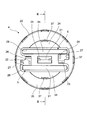
- FIG. 2 is a schematic view of the rotating body of the rice cooker as seen from the axial direction.
- 3 is a schematic cross-sectional view taken along the line III-III in FIG.
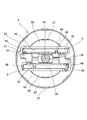
- FIG. 4 is another schematic view of the rotating body viewed from the axial direction.
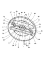
- FIG. 5 is a schematic perspective view of the rotating body.
- FIG. 1 is a schematic cross-sectional view for explaining the structure of a rice cooker according to an embodiment of the present invention.
- the rice cooker is attached to the upper part of the rice cooker body 1, the inner pot 2 housed in the rice cooker body 1, and the upper portion of the rice cooker body 1, and can be closed to cover the inner pot 2.
- a lid 3 a rotating body 4 rotatably disposed between the rice cooker body 1 and the lid 3, and two substantially rod-shaped first and second attached to the rotating body 4 so that the posture can be changed.
- Second stirring members 5 and 6 are provided.
- the 1st, 2nd stirring members 5 and 6 are examples of the stirring body of this invention.
- the 1st stirring member 5 is an example of a 1st stirring body
- the 2nd stirring member 6 is an example of a 2nd stirring body.
- the rice cooker body 1 has an outer case 7 and an inner case 8 arranged in the outer case 7.
- the inner case 8 holds the inner pot 2.
- the inner case 8 is formed of a material having heat resistance and electrical insulation.
- an IH (induction heating) heater 9 having an induction coil and a temperature sensor 10 for detecting the temperature of the inner pot 2 are attached to the bottom of the inner case 8.
- the IH heater 9 is an example of the heating unit of the present invention.
- the inner pot 2 is formed of a clad material containing a magnetic material.
- rice 50 and water 51 enter the inner pot 2.
- an annular flange portion 2 a is provided on the edge of the opening at the upper end of the inner pot 2.
- Rice 50 and water 51 are examples of the object to be heated of the present invention.
- the lid 3 is detachably attached to the outer lid 12 whose rear end is pivotably attached to the rear portion of the rice cooker body 1 by the pivot mechanism 11 and to the inner pan 2 side of the outer lid 12. And an inner lid 13.
- a rotating body 4 is rotatably attached to the inner lid 13.
- a single DC (direct current) brushless motor 15 for rotary stirring is attached to the outer lid 12 so as to be positioned in the vicinity of the rotation mechanism 11. More specifically, a rotary stirring DC brushless motor 15 and a timing belt 16 are accommodated in the outer lid 12.
- the timing belt 16 is wound around a part of the outer periphery of the small pulley 17 attached to the drive shaft 15 a of the DC brushless motor 15 for rotary stirring and a part of the outer periphery of the large pulley 18 attached to the input shaft 19.
- the rotary stirring DC brushless motor 15 is an example of the drive unit of the present invention.
- the first and second stirring members 5 and 6 are made of heat-resistant resin (for example, POM (polyacetal) or fluorine-based resin), and are formed separately from each other. Moreover, the 1st, 2nd stirring members 5 and 6 have 1st edge part 5a, 6a and 2nd edge part 5b, 6b located in the opposite side to this 1st edge part 5a, 6a. ing. Further, the first end portions 5 a and 6 a of the first and second stirring members 5 and 6 are rotatably attached to the rotating body 4. Moreover, the DC brushless motor 15 for rotary stirring generates the driving force for rotating the rotating body 4 in the first direction (the direction corresponding to the arrow R direction in FIG.
- POM polyacetal
- fluorine-based resin fluorine-based resin
- the DC brushless motor 15 for rotating agitation generates first and second agitating members by generating a driving force for rotating the rotating body 4 in the second direction (direction corresponding to the direction of arrow L in FIG. 5).
- the second end portions 5 b and 6 b approach the rotating body 4, and are in a lying state with respect to the rotating surface of the rotating body 4.
- a control device for controlling the heater 9, the DC brushless motor 15 for rotary stirring, and the like are installed.
- FIG. 2 is a schematic view of the rotating body 4 as viewed from the direction perpendicular to the rotating surface of the rotating body 4 on the inner pot 2 side (the side opposite to the inner lid 13 side).
- FIG. 3 is a schematic sectional view taken along line III-III in FIG.
- illustration of a part of component part of the rotary body 4 is abbreviate
- the rotating body 4 has a container-shaped rotating body main body 20 as shown in FIG.
- a first miter gear mounting portion 21 having a shape that bulges toward the inner pot 2 is provided at the center of the surface of the rotating body 20 on the inner pot 2 side.
- the first miter gear mounting portion 21 has a plurality of drain holes 25 for returning water that has entered between the first miter gear mounting portion 21 and the gear cover 24 (see FIG. 4) into the inner pot 2. is doing.
- the drain hole 25 has a substantially rectangular shape when viewed from the inner pot 2 side, and extends from the surface on the inner pot 2 side of the first miter gear mounting portion 21 to the outer surface in the radial direction.
- the gear cover 24 is an example of the cover of the present invention.
- the drain hole 25 is an example of the through hole of the present invention.
- the peripheral part of the surface of the rotating body 20 on the inner pot 2 side is on the one side of the first miter gear mounting part 21 and has a shape that bulges toward the inner pot 2 side.
- the miter gear mounting part 22 and the 3rd miter gear mounting part 23 of the shape which exists in the other side of the 1st miter gear mounting part 21, and bulges toward the inner pot 2 side are provided.
- the water that has entered between the second and third miter gear mounting portions 22 and 23 and the gear cover 24 is applied to the non-curved surfaces on the radially outer sides of the second and third miter gear mounting portions 22 and 23.
- a drain hole 26 is provided for returning to the inner pot 2.
- a drain hole 27 is provided for returning to the inner pot 2. Thereby, almost all of the drainage holes 27 are opened outward in the radial direction.
- the shape which looked at the drain hole 27 from the inner pot 2 side is a substantially rectangular shape.
- the drain hole 27 is an example of the through hole of the present invention.
- the rotary body 20 is provided with first and second accommodation holes 28 and 29 for accommodating the first and second stirring members 5 and 6.
- the first accommodation hole 28 is located on one side of the first miter gear mounting portion 21, the second miter gear mounting portion 22, and the third miter gear mounting portion 23, while the second accommodation hole 29. Is located on the other side of the first miter gear mounting portion 21, the second miter gear mounting portion 22, and the third miter gear mounting portion 23.
- first and second stirring members 5 and 6 are accommodated in the first and second accommodation holes 28 and 29, the first and second stirring members 5 and 6 are accommodated in the first and second accommodation holes 28. , 29 are closed, and the first surfaces 91 and 94 which are partial surfaces of the first and second stirring members 5 and 6 are exposed to the inner pot 2 side. At this time, the first surfaces 91 and 94 are substantially parallel to the rotation surface of the rotating body 4.
- the first and second stirring members 5 and 6 have a substantially triangular cross section, and the width becomes narrower from the lower side to the upper side in the drawing. More specifically, the first and second stirring members 5 and 6 have first surfaces 91 and 94, second surfaces 92 and 95, and third surfaces 93 and 96.
- the first surfaces 91 and 94 are in relation to the rotation surface of the rotating body 4.
- the second surfaces 92 and 95 are substantially parallel, the second surfaces 92 and 95 are substantially perpendicular to the rotation surface of the rotating body 4, and the third surfaces 93 and 96 are inclined with respect to the rotation surface of the rotating body 4.
- the first surfaces 91 and 94 are in relation to the rotation axis of the rotating body 4.
- the second surfaces 92 and 95 are substantially parallel to the rotation axis of the rotating body 4, and the third surfaces 93 and 96 are inclined with respect to the rotation axis of the rotating body 4.
- the surface of the rotating body 20 on the inner pot 2 side includes a plurality of umbrella-shaped tapered surfaces. More specifically, a plurality of first inclined surfaces 34 and a second inclined surface 35 positioned radially outward from the first inclined surface 34 are provided on the surface of the rotating body 4 on the inner pan 2 side. Forming.
- the first and second inclined surfaces 34 and 35 are surfaces formed such that when the lid 3 is closed, the outer edge in the radial direction is lower than the inner edge in the radial direction.
- the outer edge of the first inclined surface 34 in the radial direction is connected to the outer edge of the second inclined surface 35 in the radial direction via a step 36.
- a plurality of drain holes 37 having a substantially circular arc shape when viewed from the inner pot 2 side are provided at the radially outer edges of the first and second inclined surfaces 34 and 35. Thereby, the water which entered between the inner lid 13 and the rotary body 20 can be returned into the inner pot 2.
- a third inclined surface 62 inclined similar to the first inclined surface 34 and a fourth inclined surface similar to the second inclined surface 35 are provided on the surface of the rotating body 20 on the inner lid 13 side.
- An inclined surface 63 is provided on the surface of the rotating body 20 on the inner lid 13 side.
- FIG. 4 is a schematic view of the rotating body 4 as viewed from the direction perpendicular to the rotating surface of the rotating body 4 on the inner lid 13 side. 5 shows a state in which the inner lid 13 side of the rotating body 4 from which the input shaft 19, the gear cover 24, and the bearing portion 38 (see FIGS. 1 and 4) are removed is inclined with respect to the rotating surface of the rotating body 4.
- FIG. 5 shows a state in which the inner lid 13 side of the rotating body 4 from which the input shaft 19, the gear cover 24, and the bearing portion 38 (see FIGS. 1 and 4) are removed is inclined with respect to the rotating surface of the rotating body 4.
- the rotating body 4 includes an input shaft 19, a gear cover 24, a bearing portion 38, a first miter gear 39, a second miter gear 40, in addition to the rotating body main body 20.
- Third miter gear 41, fourth miter gear 42, fifth miter gear 43, sixth miter gear 44, seventh miter gear 45, first transmission shaft 46, first rotation shaft 47, A second transmission shaft 48 and a second rotation shaft 49 are provided.
- the third miter gear 41, the first transmission shaft 46, the second miter gear 40, the first miter gear 39, the fifth miter gear 43, the second transmission shaft 48, and the second miter gear 40 are The rotary body 20 is arranged substantially in a straight line along the radial direction.
- first stirring member 5 and the second stirring member 6 are arranged substantially symmetrically with respect to the plane including the central axes of the first transmission shaft 46, the input shaft 19 and the second transmission shaft 48. ing. Further, when the position where the first rotation shaft 47 is connected to the first stirring member 5 is rotated by 180 ° around the input shaft 19, the second rotation shaft 49 is moved to the second stirring member 6. It almost coincides with the position connected to. In other words, when the rotation center of the first stirring member 5 is rotated by 180 ° around the rotation axis of the rotating body 4, it substantially overlaps the rotation center of the second stirring member 6.
- the first miter gear 39, the second miter gear 40, the third miter gear 41, the fourth miter gear 42, the fifth miter gear 43, the sixth miter gear 44, and the seventh miter gear 45 Is an example of a plurality of gears of the present invention.
- the rotating body 20, the gear cover 24, and the first miter gear 39 and other gears can be washed with water.
- the input shaft 19 is provided so as to be rotatable with respect to the rotary body 20 and the bearing portion 38.
- a first miter gear 39 is fixed to the end of the input shaft 19 on the rotating body 20 side.
- the bearing portion 38 is detachably fitted in a through hole (not shown) provided in the inner lid 13. When the bearing portion 38 is fitted into the through hole, the end of the input shaft 19 opposite to the rotating body 20 side enters between the outer lid 12 and the inner lid 13 and is connected to the small pulley 17. It is supposed to be.
- the first miter gear 39 meshes with the second miter gear 40.
- the second miter gear 40 is fixed to the radially inner end of the first transmission shaft 46, while the third miter gear 41 is secured to the radially outer end of the first transmission shaft 46.
- the second miter gear 40, the first transmission shaft 46, and the third miter gear 41 are integrally rotated.
- the third miter gear 41 is in mesh with the fourth miter gear 42.
- the fourth miter gear 42 and the first end portion 105a of the first agitating member 5 are connected by a first rotating shaft 47, and the fourth miter gear 42, the first agitating member 5 and the first agitating member 5 are connected.
- the rotating shaft 47 is integrated. In this state, when the first miter gear 39 rotates, the first stirring member 5 rotates around the first rotation shaft 47 within a certain range.
- first miter gear 39 meshes with the fifth miter gear 43.
- the fifth miter gear 43 is fixed to the radially inner end of the second transmission shaft 48, while the sixth miter gear 44 is secured to the radially outer end of the second transmission shaft 48.
- the fifth miter gear 43, the first transmission shaft 46, and the sixth miter gear 44 are integrally rotated.
- the sixth miter gear 44 meshes with the seventh miter gear 45.
- the seventh miter gear 45 and the first end 6a of the second agitating member 6 are connected by a second rotating shaft 49, and the seventh miter gear 45, the second agitating member 6 and the second agitating member 6 are connected.
- the rotating shaft 49 is integrated.
- the second and fifth miter gears 40 and 43 are rotatably mounted in first and second recesses 52 and 53 formed in the first miter gear mounting portion 21.
- the spaces in the first and second recesses 52 and 53 communicate with the space in the inner pot 2 through the drain hole 25 when the lid 3 is closed.
- the third and fourth miter gears 41 and 42 are rotatably mounted in a third recess 54 provided in the second miter gear mounting portion 22.
- the space in the third recess 54 communicates with the space in the inner pot 2 through the drain holes 26 and 27 when the lid 3 is closed.
- the sixth and seventh miter gears 44 and 45 are rotatably mounted in a fourth recess 55 provided in the third miter gear mounting portion 23.
- the space in the fourth recess 55 communicates with the space in the inner pot 2 through the drain holes 26 and 27 when the lid 3 is closed.
- the gear cover 24 is in contact with the first and second stirring members 5 and 6 to limit the rotation of the first and second stirring members 5 and 6 in the arrow U direction. , 57.
- First and second magnets 58 and 59 are attached to the lower surfaces of the first and second stoppers 56 and 57 (the surfaces on the first and second stirring members 5 and 6 side).
- the third and fourth magnets 60 and 61 having magnetic poles opposite to the magnetic poles of the first and second magnets 58 and 59 are connected to the first and second stirring members 5 and 6 by the first and second magnets.
- the magnets 58 and 59 are attached at locations where they can be contacted.
- the gear cover 24 can be attached to and detached from the rotary body 20.
- the miter gear 44, the seventh miter gear 45, the first transmission shaft 46, and the second transmission shaft 48 can be covered with the gear cover 24.
- a snap-fit structure is preferably used as the attachment / detachment structure of the gear cover 24.
- the rotation of the first and second stirring members 5 and 6 in the direction of arrow D is limited by a part of the peripheral edge of the first and second accommodation holes 28 and 29. More specifically, when the first and second stirring members 5 and 6 housed in the first and second housing holes 28 and 29 are rotated in the direction of arrow D, the first and second stirring members 5 are moved. , 6 first end portions 5a, 6a are located in the vicinity of the first rotation shaft 47 and the second rotation shaft 49 in the peripheral portions of the first and second receiving holes 28, 29 (hereinafter referred to as This is referred to as “part of the peripheral portion of the first and second accommodation holes 28 and 29”), and the rotation after this contact is limited.
- the first and second stirring members 5 and 6 are locked to the rotating body 4 in a state where the distance between the first stirring member 5 and the second stirring member 6 becomes narrower as the distance from the rotating body 4 increases. Thus, it can be rotated together with the rotating body 4.
- the first stirring member 5 When the rotating body 4 is viewed from a direction perpendicular to the rotating surface of the rotating body 4, the first stirring member 5 includes the first miter gear 39, the second miter gear 40, and the third miter. Positioned on one side of the gear 41, the fourth miter gear 42, the fifth miter gear 43, the sixth miter gear 44, and the seventh miter gear 45, and the second stirring member 6 is One miter gear 39, the second miter gear 40, the third miter gear 41, the fourth miter gear 42, the fifth miter gear 43, the sixth miter gear 44, and the other of the seventh miter gear 45 Located on the side.
- the first miter gear 39, the second miter gear 39 is interposed between the first agitator 5 and the second agitator 6.
- a miter gear 40, a third miter gear 41, a fourth miter gear 42, a fifth miter gear 43, a sixth miter gear 44, and a seventh miter gear 45 are arranged.
- the first stirring member 5 is substantially parallel to the second stirring member 6.
- the condensed water is It flows on the third and fourth inclined surfaces 62 and 63 by its own weight toward the outside in the radial direction.
- the condensed water can be dropped from the drain hole 37 to the lower side of the rotating body 20 and returned to the inner pot 2. Therefore, the surface on the inner lid 13 side of the rotating body 20 can be prevented from becoming unsanitary, and the surface can be kept clean.
- the condensed water generated on the rotating body main body 20 passes between the rotating body main body 20 and the gear cover 24 and passes through the first recess 52, the second recess 53, the third recess 54, and the fourth.
- the rotating body 4 is rotated by the driving force of the rotary stirring DC brushless motor 15, the first concave portion 52, the second concave portion 53, the third concave portion 54, and the fourth concave portion 55 are entered. Centrifugal force acts on the condensed water.
- almost half of the drain holes 25 are opened outward in the radial direction, and almost all of the drain holes 27 are opened outward in the radial direction.
- the inner pot 2 is stored in the rice cooker body 1.
- the lid 3 is closed so as to cover 2.
- the first and second stirring members 5 and 6 are accommodated in the first and second accommodation holes 28 and 29 and are in a lying state.
- the driving force of the rotary stirring DC brushless motor 15 is transmitted to the input shaft 19 of the rotating body 4 to rotate the first miter gear 39 in the direction of arrow R.
- the 1st, 2nd stirring members 5 and 6 rotate to the arrow D direction, as shown in FIG. 1 in the state which the rotary body 4 does not rotate.
- the rotation of the first and second stirring members 5 and 6 in the direction of the arrow D is such that the first end portions 5a and 6a of the first and second stirring members 5 and 6 are in the first and second accommodation holes 28, respectively. , 29 abuts against a part of the peripheral edge and stops.
- the driving force of the DC brushless motor 15 for rotary stirring is transmitted to the input shaft 19 of the rotating body 4 and the first miter gear 39 is rotated in the direction of arrow R, the first and second stirring members 5, 6 Rotates together with the rotating body 4.
- the rice 50 and the water 51 in the inner pot 2 can be stirred by the first and second stirring members 5 and 6.
- the driving force of the rotary stirring DC brushless motor 15 is transmitted to the input shaft 19 of the rotating body 4 to rotate the first miter gear 39 in the direction of arrow L (see FIG. 5). .
- the first and second stirring members 5 and 6 are rotated in the direction of the arrow U in a state where the rotating body 4 does not rotate, and are accommodated in the first and second accommodation holes 28 and 29.
- the first and second stoppers 56 and 57 come into contact with the first and second stirring members 5 and 6, thereby rotating the first and second stirring members 5 and 6 in the direction of arrow U. Stop.
- the second end portions 5b and 6b of the first and second stirring members 5 and 6 are not reliably caught on the inner pot 2, and the lid 3 can be easily opened.
- the gear cover 24 includes a first miter gear 39, a second miter gear 40, a third miter gear 41, a fourth miter gear 42, a fifth miter gear 43, a sixth miter gear 44, and a first miter gear 44. Since the 7 miter gears 45 are covered, it is possible to prevent foreign matter from getting into these gears. Accordingly, the first miter gear 39, the second miter gear 40, the third miter gear 41, the fourth miter gear 42, the fifth miter gear 43, the sixth miter gear 44, and the seventh miter gear. It can be prevented that the posture of the first and second stirring members 5 and 6 cannot be changed due to the fact that 45 does not rotate properly.
- gear cover 24 can be attached to and detached from the rotating body 20, the gear cover 24 can be removed from the rotating body 20, and the portion covered with the gear cover 24 can be easily cleaned.
- the entire rotating body 4 can be washed with water, so that the rotating body 4 can be easily cleaned.
- the rotation of the first and second stirring members 5 and 6 in the directions of arrows D and U and the rotation of the rotating body 4 are performed by the driving force of one rotary stirring DC brushless motor 15. Yes. Therefore, compared with the case where the motor for rotating the said 1st, 2nd stirring members 5 and 6 to the arrow D direction and the arrow U direction and the motor for rotating the rotary body 4 are provided separately, The rice cooker can be downsized.
- the rotating body 4 Since the rotating body 4 is attached to the inner lid 13, the rotating body 4 moves together with the lid 3 when the lid 3 is opened. Therefore, when the inner pot 2 is put in and out of the rice cooker body 1, the rotating body 4 can be prevented from getting in and out of the inner pot 2.
- the first and second stirring members 5 and 6 are raised with respect to the rotating surface of the rotating body 4, the first and second stirring members 5 and 6 are attached to the rice 50 on the rotating body 4 side. It contacts not only the water 51 but also the rice 50 and the water 51 on the bottom side of the inner pot 2. Therefore, by rotating the first and second stirring members 5 and 6 together with the rotating body 4 while standing with respect to the rotating surface of the rotating body 4, the rice 50 and the water 51 on the rotating body 4 side are caused to rotate. While being able to fully stir, the rice 50 and the water 51 near the bottom part of the inner pot 2 can also be sufficiently stirred.
- the rice 50 and water 51 in the inner pot 2 can be sufficiently reduced with low vibration. Can be stirred.
- the distance between the first stirring member 5 and the second stirring member 6 is the rotating body 4. If it becomes narrow as it leaves
- the rice 50 and the water 51 in the vicinity of the center portion in the inner pot 2 can be sufficiently stirred by rotating with the rotating body 4 while being in a state of becoming narrower as the distance from the outer periphery, and the peripheral edge in the inner pot 2
- the rice 50 and the water 51 in the vicinity of the section can be sufficiently stirred.
- the rotating body 4 in a state where the first and second stirring members 5 and 6 are accommodated in the first and second accommodation holes 28 and 29 is viewed from a direction perpendicular to the rotation surface of the rotating body 4.
- the first and second agitating members 5 and 6 are the first miter gear 39, the second miter gear 40, the third miter gear 41, the fourth miter gear 42, and the fifth miter. Since they are on the sides of the gear 43, the sixth miter gear 44, and the seventh miter gear 45, they do not overlap with these gears. Therefore, in the above state, the thickness of the structure including the first and second stirring members 5 and 6 and the rotating body 4 can be reduced.
- the rotating body 4 in a state where the first and second stirring members 5 and 6 are accommodated in the first and second accommodation holes 28 and 29 is viewed from a direction perpendicular to the rotation surface of the rotating body 4.
- the first miter gear 39, the second miter gear 40, the third miter gear 41, and the fourth miter gear 42 are disposed between the first stirring member 5 and the second stirring member 6. Since the fifth miter gear 43, the sixth miter gear 44, and the seventh miter gear 45 are positioned, the rotation of the rotating body 4 can be stabilized even if the rotating body 4 is rotated in that state. it can. Therefore, vibration of the rotating body 4 can be reduced when the rotating body 4 in the above state rotates.
- the rotation center of the first stirring member 5 is substantially overlapped with the rotation center of the second stirring member 6 when rotated about 180 ° around the rotation axis of the rotating body 4. Even if the rotating body 4 is rotated in a state where the angle formed by the first and second stirring members 5 and 6 with respect to the rotating surface of the body 4 is 80 °, the rotation of the rotating body 4 can be stabilized. it can.
- the rice 50 and the water 51 can fully be stirred only by rotating the rotary body 4 at about 150 rpm.
- the two first and second stirring members 5 and 6 are attached to the rotating body 4 so that the posture can be changed.
- the stirring member is disposed on the side of the first miter gear 39, the second miter gear 40, ..., the sixth miter gear 44, and the seventh miter gear 45, the stirring member and This is preferable because the thickness of the structure including the rotating body 4 can be reduced.
- first and second stirring members 5 and 6 having a substantially rod shape are used.
- first and second members having a shape other than a substantially rod shape for example, a substantially L-shaped side view.
- a stirring member may be used.
- the first miter gear 39, the second miter gear 40 when the rotating body 4 is viewed from a direction perpendicular to the rotating surface of the rotating body 4, the first miter gear 39, the second miter gear 40,.
- the first agitating member 5 is arranged on one side of the seventh miter gear 45, and the first miter gear 39, the second miter gear 40, ..., the sixth miter gear 44 and the seventh miter gear 45 are arranged.
- the second agitating member 6 is disposed on the other side of the miter gear 45, the first miter gear 39, the second miter gear 40,..., The sixth miter gear 44, and the seventh miter
- the first and second stirring members 5 and 6 may be disposed on one side of the gear 45.
- the first and second stirring members 5, 6 are rotated by the first miter gear 39, the second miter gear 40,..., The sixth miter gear 44, the seventh miter gear 45, and the like. Or the rotating body 4 was rotated, but the gears other than the first miter gear 39, the second miter gear 40, ..., the sixth miter gear 44 and the seventh miter gear 45, The first and second stirring members 5 and 6 may be rotated or the rotator 4 may be rotated by another power transmission mechanism.
- the inner pot 2 is induction-heated, but the inner pot 2 may be resistance-heated, for example.
- a resistance heater may be used as an example of the heating unit of the present invention instead of the IH heater 9.
- the first and second stirring members 5 and 6 when the first and second stirring members 5 and 6 are locked to the rotating body 4 and rotate together with the rotating body 4, the first and second stirring members with respect to the rotating surface of the rotating body 4.
- the angle formed by 5 and 6 is 80 °, it may be 75 ° or 85 °, for example.
- the first stirring member 5 is formed with respect to the rotation surface of the rotating body 4.
- the angle is the same as the angle formed by the second stirring member 6 with respect to the rotating surface of the rotating body 4, but the angle formed by the first stirring member 5 with respect to the rotating surface of the rotating body 4 is You may make it differ from the angle which the 2nd stirring member 6 comprises with respect to 4 rotating surfaces. When it does in this way, the part which the 1st, 2nd stirring members 5 and 6 contact in the rice 50 or the water 51 can be increased.
- the first and second stirring members 5 and 6 have a substantially triangular cross section, but may have a substantially trapezoidal cross section. Also in this case, the first and second stirring members 5 and 6 are accommodated in the state where the first and second stirring members 5 and 6 are accommodated in the first and second accommodation holes 28 and 29. It is preferable to make the width narrower with increasing distance from the inner pot 2 side.
- the gear cover 24 is provided with the first and second stoppers 56 and 57.
- first and second stoppers having a notch at the tip may be provided.
- first and second agitating members 5 and 6 are accommodated in the first and second accommodation holes 28 and 29, for example, hemispherical shapes that are fitted and locked in the notches.
- Protrusions may be provided on the first and second stirring members 5 and 6.
- first and second stoppers 56 and 57 are provided on the gear cover 24.
- first and second stoppers having hemispherical protrusions may be provided at the tip.
- the notches to which the projections are fitted and locked are You may provide in the 1st, 2nd stirring members 5 and 6.
- the gear cover 24 may be provided with a through hole that opens at least partially toward the outside in the radial direction of the rotating body.
- the rotator 4 and the gear cover 24 may be made of metal, or may be made of heat-resistant resin like the first and second stirring members 5 and 6. Also good.
- the rice 50 and the water 51 are stirred and heated, but the jam and sauce can be stirred and heated. That is, the rice cooker can be suitably used for cooking jams and sauces. Moreover, when the said rice cooker is used for cooking of a jam, a sauce, etc., the effect similar to the said embodiment is acquired.
- the cooking device of the present invention is not limited to a rice cooker, and may be an oven such as a range or a steam cooking device. That is, the cooking device of the present invention may be any cooking device as long as the cooking device has a housing portion that can store the heating object and can heat the heating object.
Landscapes
- Engineering & Computer Science (AREA)
- Food Science & Technology (AREA)
- Cookers (AREA)
Abstract
加熱調理器は、被加熱物を収容する収容部と、収容部が収納される加熱調理器本体と、加熱調理器本体内に配置され、被加熱物を加熱するための加熱部と、加熱調理器本体の上部に開閉自在に取り付けられ、収容部を覆うように閉じることが可能な蓋体と、加熱調理器本体と蓋体との間に回転自在に配置され、蓋体に着脱可能な回転体(4)と、回転体(4)に姿勢変更可能に取り付けられ、収容部内の被加熱物を攪拌する第1,第2の攪拌部材(5,6)と、回転体(4)を回転させるための駆動力を発生する駆動部とを備える。回転体(4)には、少なくとも一部が回転体(4)の半径方向外側に向かって開口する貫通孔(25,27)が設けられている。
Description
本発明は加熱調理器に関する。
従来、加熱調理器の一例である炊飯器としては、特開2008-278924号公報(特許文献1)に開示されたものがある。この炊飯器は、被加熱物の米を収容する内鍋と、この内鍋が収納される炊飯器本体と、この炊飯器本体の上部に回動自在に取り付けられ、内鍋の開口を開閉する蓋体とを備えている。
上記蓋体において閉鎖時に下面となる面(内鍋の内面に対向する面)には、断面形状がほぼ山の字形状の攪拌体の上端部を回転自在に取り付けている。この攪拌体は、蓋体の閉鎖時、内鍋の内部空間の上端から内鍋の内部空間の下端近傍にわたって位置する。
上記蓋体内には回転駆動装置が設置されており、この回転駆動装置によって攪拌体を回転させて、内鍋内の御飯をほぐそうとしている。
しかしながら、上記従来の炊飯器では、蓋体の閉鎖時、攪拌体が内鍋の内部空間の上端から内鍋の内部空間の下端近傍まで延び、攪拌体の上端部を蓋体の内面に取り付けているため、蓋体を開こうとしても、攪拌体の下端部が内鍋に引っ掛かって、蓋体を開くことができないという問題がある。
上記問題を解決する方法としては、炊飯器本体と蓋体との間に回転体を回転自在に配置し、回転体に攪拌体の一方の端部を回動自在に取り付ける方法が考えられる。
しかしながら、上記方法を採用した炊飯器で炊飯すると、内鍋内の水蒸気が回転体内に進入してしまう。その結果、上記回転体内で凝縮水が生じるため、回転体内でカビが繁殖してしまう。すなわち、上記回転体内が不衛生になるという問題が新たに生じてしまう。
そこで、本発明の課題は、回転体内が不衛生になるのを容易に防ぐことができる加熱調理器を提供することにある。
上記課題を解決するため、本発明の加熱調理器は、
被加熱物を収容する収容部と、
上記収容部が収納される加熱調理器本体と、
上記加熱調理器本体内に配置され、上記被加熱物を加熱するための加熱部と、
上記加熱調理器本体の上部に開閉自在に取り付けられ、上記収容部を覆うように閉じることが可能な蓋体と、
上記加熱調理器本体と上記蓋体との間に回転自在に配置され、上記蓋体に着脱可能な回転体と、
上記回転体に姿勢変更可能に取り付けられ、上記収容部内の上記被加熱物を攪拌する攪拌体と、
上記回転体を回転させるための駆動力を発生する駆動部と
を備え、
上記回転体には、少なくとも一部が上記回転体の半径方向外側に向かって開口する貫通孔が設けられていることを特徴としている。
被加熱物を収容する収容部と、
上記収容部が収納される加熱調理器本体と、
上記加熱調理器本体内に配置され、上記被加熱物を加熱するための加熱部と、
上記加熱調理器本体の上部に開閉自在に取り付けられ、上記収容部を覆うように閉じることが可能な蓋体と、
上記加熱調理器本体と上記蓋体との間に回転自在に配置され、上記蓋体に着脱可能な回転体と、
上記回転体に姿勢変更可能に取り付けられ、上記収容部内の上記被加熱物を攪拌する攪拌体と、
上記回転体を回転させるための駆動力を発生する駆動部と
を備え、
上記回転体には、少なくとも一部が上記回転体の半径方向外側に向かって開口する貫通孔が設けられていることを特徴としている。
上記構成によれば、上記回転体を回転させると、回転体内の例えば液体に遠心力が作用する。このとき、少なくとも一部が回転体の半径方向外側に向かって開口する貫通孔を回転体に設けているので、その遠心力で液体が上記貫通孔を通って回転体外に出る。このように、上記蓋体から回転体を取り外して分解掃除しなくても、回転体を回転させるだけで回転内の液体を回転体外に出すことができる。したがって、上記回転体内が不衛生になるのを容易に防ぐことができ、回転体内を清潔に保つことができる。
また、上記攪拌体の姿勢を変更して、収容部内の被加熱物に攪拌体を接触させる。この状態で、上記駆動部の駆動力によって回転体を回転させると、攪拌体を回転体と共に回転させて、収容部内の被加熱物を攪拌体で攪拌することができる。
また、上記攪拌体の姿勢を変更することにより、蓋体の開放時、攪拌体の一部が収容部に引っ掛からないようにすることができる。したがって、上記攪拌体が蓋体の開放を阻害するのを防ぐことができる。
なお、例えば固体であっても貫通孔を通過できるのであれば、回転体の回転による遠心力で貫通孔から回転体外へ出せる。
一実施形態の加熱調理器では、
上記回転体は、
回転体本体と、
上記回転体本体に搭載され、上記攪拌体の姿勢を変更するための複数の歯車と、
上記歯車を覆うと共に、上記回転体本体に着脱可能なカバーと
を有する。
上記回転体は、
回転体本体と、
上記回転体本体に搭載され、上記攪拌体の姿勢を変更するための複数の歯車と、
上記歯車を覆うと共に、上記回転体本体に着脱可能なカバーと
を有する。
上記実施形態によれば、上記カバーが歯車を覆うので、歯車への異物の噛み込みを防ぐことができる。したがって、上記歯車がうまく回らないことで攪拌体の姿勢変更ができなくなるのを防ぐことができる。
また、上記カバーは回転体本体に着脱可能であるので、回転体本体からカバーを取り外して、カバーで覆われていた箇所を容易に清掃できる。
一実施形態の加熱調理器では、
上記攪拌体は、第1攪拌体と、上記第1攪拌体とは別体である第2攪拌体とからなる。
上記攪拌体は、第1攪拌体と、上記第1攪拌体とは別体である第2攪拌体とからなる。
上記実施形態によれば、上記攪拌体が、第1攪拌体と、この第1攪拌体とは別体である第2攪拌体とからなるので、第1,第2攪拌体で収容部内の被加熱物を適度に動かすことができる。したがって、上記被加熱物の攪拌を低振動で十分に行うことができる。
一実施形態の加熱調理器では、
上記回転体の回転面に対して垂直な方向から上記回転体を見たとき、上記第1,第2攪拌体は上記複数の歯車の側方に位置する。
上記回転体の回転面に対して垂直な方向から上記回転体を見たとき、上記第1,第2攪拌体は上記複数の歯車の側方に位置する。
ここで、「回転体の回転面」とは、回転体の回転軸に対して垂直な面を指す。
上記実施形態によれば、上記回転体の回転面に対して垂直な方向から回転体を見たとき、第1,第2攪拌体は複数の歯車の側方に位置するので、回転体の回転軸方向において第1,第2攪拌体が複数の歯車と重なっているときに比べて、回転体および第1,第2攪拌体を有する構造体の厚さを薄くすることができる。
一実施形態の加熱調理器では、
上記回転体の回転面に対して垂直な方向から上記回転体を見たとき、上記第1攪拌体と上記第2攪拌体との間に上記複数の歯車が位置するように、上記第1,第2攪拌体が設けられている。
上記回転体の回転面に対して垂直な方向から上記回転体を見たとき、上記第1攪拌体と上記第2攪拌体との間に上記複数の歯車が位置するように、上記第1,第2攪拌体が設けられている。
上記実施形態によれば、上記回転体の回転面に対して垂直な方向から回転体を見たとき、第1攪拌体と第2攪拌体との間に複数の歯車が位置するように、第1,第2攪拌体を設けることにより、回転体の回転を安定させることができる。したがって、上記回転体の回転時、回転体の振動を低減できる。
本発明の加熱調理器によれば、被加熱物を収容する収容部と、この収容部が収納される加熱調理器本体と、加熱調理器本体の上部に開閉自在に取り付けられ、収容部を覆うように閉じることが可能な蓋体と、加熱調理器本体と蓋体との間に回転自在に配置され、蓋体に着脱可能な回転体とを備え、回転体には、少なくとも一部が回転体の半径方向外側に向かって開口する貫通孔が設けられていることによって、回転体内の例えば液体に遠心力を作用させて、その液体を上記貫通孔から回転体外に出すことができるので、回転体内が不衛生になるのを容易に防ぐことができ、回転体内を清潔に保つことができる。
また、上記回転体に姿勢変更可能に取り付けられ、収容部内の被加熱物を攪拌する攪拌体を備えるので、攪拌体の姿勢を変更して、収容部内の被加熱物に攪拌体を接触させた状態で、駆動部の駆動力によって回転体を回転させると、攪拌体を回転体と共に回転させて、収容部内の被加熱物を攪拌体で攪拌することができる。
また、上記攪拌体の姿勢を変更することにより、蓋体の開放時、攪拌体の一部が収容部に引っ掛からないようにすることができるので、攪拌体が蓋体の開放を阻害するのを防ぐことができる。
以下、本発明の炊飯器を図示の実施の形態により詳細に説明する。
図1は、本発明の一実施形態の炊飯器の構造を説明するための模式断面図である。
上記炊飯器は、炊飯器本体1と、この炊飯器本体1内に収納される内鍋2と、炊飯器本体1の上部に開閉自在に取り付けられ、内鍋2を覆うように閉じることが可能な蓋体3と、炊飯器本体1と蓋体3との間に回転自在に配置された回転体4と、回転体4に姿勢変更可能に取り付けられた2本のほぼ棒形状の第1,第2の攪拌部材5,6とを備えている。なお、第1,第2の攪拌部材5,6は本発明の攪拌体の一例である。また、第1の攪拌部材5は第1攪拌体の一例であり、第2の攪拌部材6は第2攪拌体の一例である。
上記炊飯器本体1は、外ケース7と、この外ケース7内に配置された内ケース8とを有する。また、炊飯器本体1内に内鍋2を収納したときに、内ケース8が内鍋2を保持するようになっている。この内ケース8は、耐熱性および電気絶縁性を有する材料で形成されている。また、内ケース8の底部には、誘導コイルを有するIH(誘導加熱)ヒータ9と、内鍋2の温度を検知する温度センサ10とを取り付けている。なお、IHヒータ9は本発明の加熱部の一例である。
上記内鍋2は磁性材を含むクラッド材で成型されており、例えば米50や水51が内鍋2内に入る。また、内鍋2の上端の開口の縁には環状のフランジ部2aを設けている。なお、米50や水51は本発明の被加熱物の一例である。
上記蓋体3は、後端部が回動機構11によって炊飯器本体1の後部に回動自在に取り付けられた外蓋12と、その外蓋12の内鍋2側に着脱自在に取り付けられた内蓋13とを有している。また、内蓋13には回転体4を回転自在に取り付けている。
上記外蓋12には、回動機構11近傍に位置するように1つの回転攪拌用DC(直流)ブラシレスモータ15を取り付けている。より詳しくは、外蓋12内に回転攪拌用DCブラシレスモータ15およびタイミングベルト16を収容している。このタイミングベルト16は、回転攪拌用DCブラシレスモータ15の駆動軸15aに取り付けられた小プーリ17の外周の一部と、入力軸19に取り付けられた大プーリ18の外周の一部とに巻回されている。これにより、回転攪拌用DCブラシレスモータ15の駆動力はタイミングベルト16を介して回転体4の入力軸19に伝わる。なお、回転攪拌用DCブラシレスモータ15は本発明の駆動部の一例である。
上記第1,第2の攪拌部材5,6は耐熱樹脂(例えばPOM(ポリアセタール)やフッソ系樹脂)を材料とし、互いに別体に形成されている。また、第1,第2の攪拌部材5,6は、第1端部5a,6aと、この第1端部5a,6aとは反対側に位置する第2端部5b,6bとを有している。また、回転体4に第1,第2の攪拌部材5,6の第1端部5a,6aを回動自在に取り付けている。また、回転攪拌用DCブラシレスモータ15が回転体4を第1方向(図5の矢印R方向に相当する方向)に回転させるための駆動力を発生することにより、第1,第2の攪拌部材5,6は、第2端部5b,6bが回転体4から離れて回転体4の回転面に対して起立状態になる。一方、回転攪拌用DCブラシレスモータ15が回転体4を第2方向(図5の矢印L方向に相当する方向)に回転させるための駆動力を発生することにより、第1,第2の攪拌部材5,6は、第2端部5b,6bが回転体4に近づいて回転体4の回転面に対して倒伏状態になる。すなわち、回転攪拌用DCブラシレスモータ15が回転体4を第1方向,第2方向に回転させるための駆動力を発生することにより、第1,第2の攪拌部材5,6が、矢印D方向,矢印U方向に回動する。
また、上記外ケース7と内ケース8との間の空間には、ヒータ9や回転攪拌用DCブラシレスモータ15などを制御する制御装置(図示せず)などを設置している。
図2は、上記回転体4の内鍋2側(内蓋13側とは反対側)を回転体4の回転面に対して垂直な方向から見た概略図である。また、図3は、図2のIII-III線から見た模式断面図である。なお、図3では、回転体4の構成部の一部の図示を省略している。
上記回転体4は、図2に示すように、器形状の回転体本体20を有している。この回転体本体20の内鍋2側の表面の中央部には、内鍋2側に向かって膨出する形状の第1のマイタ歯車搭載部21を設けている。第1のマイタ歯車搭載部21は、第1のマイタ歯車搭載部21とギアカバー24(図4参照)との間に進入した水を内鍋2内に戻すための水抜き孔25を複数有している。この水抜き孔25は、内鍋2側から見た形状がほぼ矩形状であり、第1のマイタ歯車搭載部21の内鍋2側の表面から半径方向外側の表面に渡って延びている。これにより、水抜き孔25は、ほぼ半分が半径方向外側に向かって開口し、残りが内鍋2側に向かって開口している。なお、ギアカバー24は本発明のカバーの一例である。また、水抜き孔25は本発明の貫通孔の一例である。
また、上記回転体本体20の内鍋2側の表面の周縁部には、第1のマイタ歯車搭載部21の一側方にあって内鍋2側に向かって膨出する形状の第2のマイタ歯車搭載部22と、第1のマイタ歯車搭載部21の他側方にあって内鍋2側に向かって膨出する形状の第3のマイタ歯車搭載部23とを設けている。この第2,第3のマイタ歯車搭載部22,23の半径方向外側の非湾曲表面には、第2,第3のマイタ歯車搭載部22,23とギアカバー24との間に進入した水を内鍋2内に戻すための水抜き孔26を設けている。また、第2,第3のマイタ歯車搭載部22,23の半径方向外側の湾曲表面にも、第2,第3のマイタ歯車搭載部22,23とギアカバー24との間に進入した水を内鍋2内に戻すための水抜き孔27を設けている。これにより、水抜き孔27のほぼ全部が半径方向外側に向かって開口している。なお、水抜き孔27を内鍋2側から見た形状はほぼ矩形状である。また、水抜き孔27は本発明の貫通孔の一例である。
また、上記回転体本体20には、第1,第2の攪拌部材5,6を収容する第1,第2の収容孔28,29を設けている。第1の収容孔28は、第1のマイタ歯車搭載部21、第2のマイタ歯車搭載部22および第3のマイタ歯車搭載部23の一方の側方に位置する一方、第2の収容孔29は、第1のマイタ歯車搭載部21、第2のマイタ歯車搭載部22および第3のマイタ歯車搭載部23の他方の側方に位置する。内鍋2内の米50や水51を第1,第2の攪拌部材5,6で攪拌しないとき、第1,第2の収容孔28,29に第1,第2の攪拌部材5,6を収容する。また、第1,第2の収容孔28,29に第1,第2の攪拌部材5,6を収容すると、第1,第2の攪拌部材5,6が第1,第2の収容孔28,29を塞ぎ、第1,第2の攪拌部材5,6の一部の表面である第1の表面91,94が内鍋2側に露出する。このとき、第1の表面91,94は回転体4の回転面に対してほぼ平行になっている。
上記第1,第2の攪拌部材5,6は、図3に示すように、ほぼ三角形状の断面を有し、図中下方から図中上方に向かって幅が狭くなっている。より詳しくは、第1,第2の攪拌部材5,6は、第1の表面91,94、第2の表面92,95および第3の表面93,96を有する。そして、第1,第2の収容孔128,129に第1,第2の攪拌部材5,6を収容している状態において、第1の表面91,94は回転体4の回転面に対してほぼ平行であり、第2の表面92,95は回転体4の回転面に対してほぼ垂直であり、第3の表面93,96は回転体4の回転面に対して傾斜する。別の言い方をすれば、第1,第2の攪拌部材5,6が内鍋2内の米50や水51を攪拌しないとき、第1の表面91,94は回転体4の回転軸に対してほぼ垂直になり、第2の表面92,95は回転体4の回転軸に対してほぼ平行になり、第3の表面93,96は回転体4の回転軸に対して傾斜する。
また、上記回転体本体20を内鍋2側の表面には、図2,図3に示すように、複数の傘状テーパ面を含んでいる。より詳しくは、回転体4の内鍋2側の表面には、複数の第1の傾斜面34と、この第1の傾斜面34よりも半径方向外側に位置する第2の傾斜面35とを形成している。第1,第2の傾斜面34,35は、蓋体3を閉じたときに、半径方向外側の縁部が半径方向内側の縁部より低くなるように形成された面である。この第1の傾斜面34の半径方向外側の縁部は、第2の傾斜面35の半径方向外側の縁部に段部36を介して接続されている。また、第1,第2の傾斜面34,35の半径方向外側の縁部には、内鍋2側から見た形状がほぼ円弧形状である水抜き孔37を複数設けている。これにより、内蓋13と回転体本体20との間に進入した水を内鍋2内に戻すことができるようになっている。
また、上記回転体本体20の内蓋13側の表面には、第1の傾斜面34と同様に傾斜する第3の傾斜面62と、第2の傾斜面35と同様に傾斜する第4の傾斜面63とを設けている。
図4は、上記回転体4の内蓋13側を回転体4の回転面に対して垂直な方向から見た概略図である。また、図5は、入力軸19、ギアカバー24および軸受部38(図1,図4参照)を取り外した回転体4の内蓋13側を回転体4の回転面に対して傾斜した方向から見た概略図である。
上記回転体4は、図4,図5に示すように、回転体本体20の他に、入力軸19、ギアカバー24、軸受部38、第1のマイタ歯車39、第2のマイタ歯車40、第3のマイタ歯車41、第4のマイタ歯車42、第5のマイタ歯車43、第6のマイタ歯車44、第7のマイタ歯車45、第1の伝達軸46、第1の回動軸47、第2の伝達軸48および第2の回動軸49を有している。この第3のマイタ歯車41、第1の伝達軸46、第2のマイタ歯車40、第1のマイタ歯車39、第5のマイタ歯車43、第2の伝達軸48および第2のマイタ歯車40は、回転体本体20上で半径方向に沿ってほぼ一直線に並んでいる。また、第1の伝達軸46、入力軸19および第2の伝達軸48のそれぞれの中心軸を含む面に関して、第1の攪拌部材5と第2の攪拌部材6とをほぼ面対称に配置している。また、第1の回動軸47が第1の攪拌部材5に連結している位置を、入力軸19の回りに180°回転させると、第2の回動軸49が第2の攪拌部材6に連結している位置とほぼ一致する。別の言い方をすると、第1の攪拌部材5の回動中心を、回転体4の回転軸の回りに180°回転させると、第2の攪拌部材6の回動中心にほぼ重なる。なお、第1のマイタ歯車39、第2のマイタ歯車40、第3のマイタ歯車41、第4のマイタ歯車42、第5のマイタ歯車43、第6のマイタ歯車44および第7のマイタ歯車45は本発明の複数の歯車の一例である。また、回転体本体20、ギアカバー24、および、第1のマイタ歯車39などの歯車は、水洗い可能である。
上記入力軸19は回転体本体20および軸受部38に対して回転可能に設けられている。この入力軸19の回転体本体20側の端部には第1のマイタ歯車39を固定している。また、軸受部38は、内蓋13に設けられた貫通孔(図示せず)に着脱可能に嵌合している。この貫通孔に軸受部38を嵌合させたときに、入力軸19の回転体本体20側とは反対側の端部が外蓋12と内蓋13との間に入って小プーリ17に連結するようになっている。
上記第1のマイタ歯車39は第2のマイタ歯車40に歯合している。また、第1の伝達軸46の半径方向内側の端部には第2のマイタ歯車40を固定する一方、第1の伝達軸46の半径方向外側の端部には第3のマイタ歯車41を固定して、第2のマイタ歯車40、第1の伝達軸46および第3のマイタ歯車41が一体に回転するようにしている。また、第3のマイタ歯車41は第4のマイタ歯車42に歯合している。この第4のマイタ歯車42と第1の攪拌部材5の第1端部105aとを第1の回動軸47で連結し、第4のマイタ歯車42、第1の攪拌部材5および第1の回動軸47を一体化している。このような状態で、第1のマイタ歯車39が回転すると、第1の攪拌部材5が一定の範囲内において第1の回動軸47を中心に回動するようになっている。
また、上記第1のマイタ歯車39は第5のマイタ歯車43にも歯合している。また、第2の伝達軸48の半径方向内側の端部には第5のマイタ歯車43を固定する一方、第2の伝達軸48の半径方向外側の端部には第6のマイタ歯車44を固定して、第5のマイタ歯車43、第1の伝達軸46および第6のマイタ歯車44が一体に回転するようにしている。また、第6のマイタ歯車44は第7のマイタ歯車45に歯合している。この第7のマイタ歯車45と第2の攪拌部材6の第1端部6aとを第2の回動軸49で連結し、第7のマイタ歯車45、第2の攪拌部材6および第2の回動軸49を一体化している。このような状態で、第1のマイタ歯車39が回転すると、第2の攪拌部材6が一定の範囲内において第1の回動軸47を中心に回動するようになっている。
上記第2,第5のマイタ歯車40,43は、第1のマイタ歯車搭載部21に形成された第1,第2の凹部52,53に回転可能に搭載されている。この第1,第2の凹部52,53内の空間は、蓋体3の閉鎖時、水抜き孔25を介して内鍋2内の空間と連通する。
上記第3,第4のマイタ歯車41,42は、第2のマイタ歯車搭載部22に設けられた第3の凹部54に回転可能に搭載されている。この第3の凹部54内の空間は、蓋体3の閉鎖時、水抜き孔26,27を介して内鍋2内の空間と連通する。
上記第6,第7のマイタ歯車44,45は、第3のマイタ歯車搭載部23に設けられた第4の凹部55に回転可能に搭載されている。この第4の凹部55内の空間は、蓋体3の閉鎖時、水抜き孔26,27を介して内鍋2内の空間と連通する。
上記ギアカバー24は、第1,第2の攪拌部材5,6に当接して第1,第2の攪拌部材5,6の矢印U方向の回動を制限する第1,第2のストッパ56,57を有している。この第1,第2のストッパ56,57の先端部の下面(第1,第2の攪拌部材5,6側の表面)には第1,第2の磁石58,59を取り付けている。そして、第1,第2の磁石58,59の磁極とは反対の磁極を有する第3,第4の磁石60,61を、第1,第2の攪拌部材5,6において第1,第2の磁石58,59に接触可能な箇所に取り付けている。これにより、回転攪拌用DCブラシレスモータ15の非駆動時であっても、第1,第2の磁石58,59と第3,第4の磁石60,61との吸引力により、第1,第2の攪拌部材5,6の図4,図5に示すような状態つまり倒伏状態を維持できるようになっている。また、ギアカバー24は回転体本体20に着脱可能となっている。回転体本体20にギアカバー24を取り付けることにより、第1のマイタ歯車39、第2のマイタ歯車40、第3のマイタ歯車41、第4のマイタ歯車42、第5のマイタ歯車43、第6のマイタ歯車44、第7のマイタ歯車45、第1の伝達軸46および第2の伝達軸48をギアカバー24で覆うことができるようになっている。なお、ギアカバー24の着脱構造として例えばスナップフィット構造を用いるのが好ましい。
一方、上記第1,第2の攪拌部材5,6の矢印D方向の回動は、第1,第2の収容孔28,29の周縁部の一部で制限する。より詳しくは、第1,第2の収容孔28,29に収容している第1,第2の攪拌部材5,6を矢印D方向に回動させると、第1,第2の攪拌部材5,6の第1端部5a,6aが、第1,第2の収容孔28,29の周縁部において第1の回動軸47,第2の回動軸49近傍に位置する部分(以下、「第1,第2の収容孔28,29の周縁部の一部」と言う。)に当接して、この当接以降の回動が制限される。この第1,第2の収容孔28,29の周縁部の一部に、第1,第2の攪拌部材5,6の第1端部5a,6aが当接したとき、回転体4の回転面に対して第1,第2の攪拌部材5,6が成す角度は80°となっている。このような状態で、第1,第2の攪拌部材5,6を矢印D方向に回動させるための駆動力を入力軸19に与えると、第1,第2の収容孔28,29の周縁部の一部に、第1,第2の攪拌部材5,6の第1端部5a,6aが係止して、第1,第2の攪拌部材5,6が回転体4と共に回転する。すなわち、第1,第2の攪拌部材5,6は、第1の攪拌部材5と第2の攪拌部材6との間隔が回転体4から離れるにしたがって狭くなる状態で、回転体4に係止して回転体4と共に回転することができるようになっている。
また、上記回転体4の回転面に対して垂直な方向から回転体4を見たとき、第1の攪拌部材5は、第1のマイタ歯車39、第2のマイタ歯車40、第3のマイタ歯車41、第4のマイタ歯車42、第5のマイタ歯車43、第6のマイタ歯車44および第7のマイタ歯車45の一方の側方に位置し、かつ、第2の攪拌部材6は、第1のマイタ歯車39、第2のマイタ歯車40、第3のマイタ歯車41、第4のマイタ歯車42、第5のマイタ歯車43、第6のマイタ歯車44および第7のマイタ歯車45の他方の側方に位置している。すなわち、回転体4の回転面に対して垂直な方向から回転体4を見たとき、第1の攪拌部材5と第2の攪拌部材6との間に、第1のマイタ歯車39、第2のマイタ歯車40、第3のマイタ歯車41、第4のマイタ歯車42、第5のマイタ歯車43、第6のマイタ歯車44および第7のマイタ歯車45を配置している。また、第1の攪拌部材5は第2の攪拌部材6とほぼ平行になっている。
上記構成の炊飯器によれば、炊飯時、内鍋2内の水蒸気が内蓋13と回転体4との間に進入し、凝縮水が回転体本体20上で生じても、その凝縮水は第3,第4の傾斜面62,63上を自重で半径方向外側に向かって流れる。その結果、上記凝縮水を水抜き孔37から回転体本体20の下方へ落として、内鍋2内に戻すことができる。したがって、回転体本体20の内蓋13側の表面が不衛生になるのを防ぎ、その表面を清潔に保つことができる。
また、上記回転体本体20上で生じた凝縮水が、回転体本体20とギアカバー24との間を通って、第1の凹部52、第2の凹部53、第3の凹部54および第4の凹部55内に進入した場合、回転攪拌用DCブラシレスモータ15の駆動力によって回転体4が回転すると、第1の凹部52、第2の凹部53、第3の凹部54および第4の凹部55の凝縮水に遠心力が作用する。このとき、水抜き孔25のほぼ半分が半径方向外側に向かって開口し、かつ、水抜き孔27のほぼ全部が半径方向外側に向かって開口しているので、その遠心力を受けた凝縮水を、水抜き孔25から第1,第2の凹部52,53に出し、かつ、水抜き孔27から、第3,第4の凹部54,55外に出して、内鍋2内に戻すことができる。したがって、第1の凹部52、第2の凹部53、第3の凹部54および第4の凹部55内が凝縮水で不衛生になるのを防ぐことができ、第1の凹部52、第2の凹部53、第3の凹部54および第4の凹部55内を清潔に保つことができる。
また、上記内鍋2内に、所望量の米50と、この米50の量に応じた水量の水51とを入れた後、炊飯器本体1内に内鍋2を収納して、内鍋2を覆うように蓋体3を閉じる。このとき、第1,第2の攪拌部材5,6は、図5に示すように、第1,第2の収容孔28,29に収容されて倒伏状態となっている。そして、回転攪拌用DCブラシレスモータ15の駆動力を回転体4の入力軸19に伝えて、第1のマイタ歯車39を矢印R方向に回転させる。これにより、回転体4が回転しない状態で、第1,第2の攪拌部材5,6が、図1に示すように、矢印D方向に回動する。この第1,第2の攪拌部材5,6の矢印D方向の回動は、第1,第2の攪拌部材5,6の第1端部5a,6aが第1,第2の収容孔28,29の周縁部の一部に当接して停止する。さらに、回転攪拌用DCブラシレスモータ15の駆動力を回転体4の入力軸19に伝えて、第1のマイタ歯車39を矢印R方向に回転させると、第1,第2の攪拌部材5,6が回転体4と共に回転する。その結果、内鍋2内の米50および水51を第1,第2の攪拌部材5,6で攪拌することができる。
また、上記蓋体3を開ける場合、回転攪拌用DCブラシレスモータ15の駆動力を回転体4の入力軸19に伝えて、第1のマイタ歯車39を矢印L方向(図5参照)に回転させる。これにより、回転体4が回転しない状態で、第1,第2の攪拌部材5,6が、矢印U方向に回動し、第1,第2の収容孔28,29に収容される。このとき、第1,第2のストッパ56,57が第1,第2の攪拌部材5,6に当接することにより、第1,第2の攪拌部材5,6の矢印U方向の回動が停止する。その結果、第1,第2の攪拌部材5,6の第2端部5b,6bが内鍋2に確実に引っ掛からないようし、蓋体3を容易に開くことができる。
また、上記ギアカバー24が第1のマイタ歯車39、第2のマイタ歯車40、第3のマイタ歯車41、第4のマイタ歯車42、第5のマイタ歯車43、第6のマイタ歯車44および第7のマイタ歯車45を覆うので、これらの歯車への異物の噛み込みを防ぐことができる。したがって、上記第1のマイタ歯車39、第2のマイタ歯車40、第3のマイタ歯車41、第4のマイタ歯車42、第5のマイタ歯車43、第6のマイタ歯車44および第7のマイタ歯車45がうまく回らないことに起因して第1,第2の攪拌部材5,6の姿勢変更ができなくなるのを防ぐことができる。
また、上記ギアカバー24は回転体本体20に着脱可能であるので、回転体本体20からギアカバー24を取り外して、ギアカバー24で覆われていた箇所を容易に清掃できる。
また、上記回転体本体20からギアカバー24を取り外していなくても、回転体4の全体を水洗いできるので、回転体4の清掃は簡単である。
また、上記第1,第2の攪拌部材5,6の矢印D方向,矢印U方向の回動と、回転体4の回転とは、1つの回転攪拌用DCブラシレスモータ15の駆動力で行っている。したがって、上記第1,第2の攪拌部材5,6を矢印D方向,矢印U方向に回動させるためのモータと、回転体4の回転させるためのモータとを別々に設ける場合に比べて、炊飯器を小型化できる。
また、上記内蓋13に回転体4を取り付けているので、蓋体3を開くと、回転体4が蓋体3と共に移動する。したがって、上記炊飯器本体1に内鍋2を出し入れするとき、回転体4が内鍋2の出し入れに邪魔にならないようにすることができる。
また、上記第1,第2の攪拌部材5,6を回転体4の回転面に対して起立状態にしたとき、第1,第2の攪拌部材5,6が、回転体4側の米50や水51だけでなく、内鍋2の底部側の米50や水51にも接触する。したがって、第1,第2の攪拌部材5,6を、回転体4の回転面に対して起立状態にしたまま、回転体4と共に回転させることにより、回転体4側の米50や水51を十分に攪拌することができると共に、内鍋2の底部近くの米50や水51も十分に攪拌することができる。
一方、上記第1,第2の攪拌部材5,6を回転体4の回転面に対して倒伏状態にしたとき、第1,第2の攪拌部材5,6が内鍋2内の米50や水51に接触しない。したがって、第1,第2の攪拌部材5,6を、回転体4の回転面に対して倒伏状態したまま、回転体4と共に回転させても、内鍋2内の米50や水51が第1,第2の攪拌部材5,6で攪拌されないようにすることができる。
また、上記内鍋2内の米50や水51を2本の第1,第2の攪拌部材5,6で攪拌することにより、内鍋2内の米50や水51を低振動で十分に攪拌することができる。
また、上記第1,第2の攪拌部材5,6を回転体4の回転面に対して起立状態にしたとき、第1の攪拌部材5と第2の攪拌部材6との間隔が回転体4から離れるにしたがって狭くなっていると、第1,第2の攪拌部材5,6が、内鍋2内の中央部近傍の米50や水51だけでなく、内鍋2内の周縁部近傍の米50や水51にも接触する。したがって、第1,第2の攪拌部材5,6を、回転体4の回転面に対して起立状態にし、かつ、第1の攪拌部材5と第2の攪拌部材6との間隔が回転体4から離れるにしたがって狭くなる状態にしたまま、回転体4と共に回転させることにより、内鍋2内の中央部近傍の米50や水51を十分に攪拌することができると共に、内鍋2内の周縁部近傍の米50や水51も十分に攪拌することができる。
また、上記第1,第2の収容孔28,29に第1,第2の攪拌部材5,6を収容している状態の回転体4を回転体4の回転面に対して垂直な方向からを見たとき、第1,第2の攪拌部材5,6は、第1のマイタ歯車39、第2のマイタ歯車40、第3のマイタ歯車41、第4のマイタ歯車42、第5のマイタ歯車43、第6のマイタ歯車44および第7のマイタ歯車45の側方にあるので、これらの歯車と重ならない。したがって、上記状態において第1,第2の攪拌部材5,6および回転体4からなる構造体の厚さを薄くすることができる。
また、上記第1,第2の収容孔28,29に第1,第2の攪拌部材5,6を収容している状態の回転体4を回転体4の回転面に対して垂直な方向からを見たとき、第1の攪拌部材5と第2の攪拌部材6との間に、第1のマイタ歯車39、第2のマイタ歯車40、第3のマイタ歯車41、第4のマイタ歯車42、第5のマイタ歯車43、第6のマイタ歯車44および第7のマイタ歯車45を位置させているので、その状態で回転体4を回転させても、回転体4の回転を安定させることができる。したがって、上記状態の回転体4の回転時、回転体4の振動を低減できる。
また、上記第1の攪拌部材5の回動中心は、回転体4の回転軸の回りに180°回転させると、第2の攪拌部材6の回動中心にほぼ重なるようにしているので、回転体4の回転面に対して第1,第2の攪拌部材5,6が成す角度は80°になっている状態で回転体4を回転させても、回転体4の回転を安定させることができる。
また、上記炊飯器であれば、回転体4を約150rpmで回転させるだけでも、米50や水51を十分に攪拌することができる。
上記実施形態では、回転体4に姿勢変更可能に2本の第1,第2の攪拌部材5,6を取り付けていたが、回転体4に姿勢変更可能に1本の攪拌部材を取り付けてもよい。このようにする場合、上記攪拌部材は、第1のマイタ歯車39、第2のマイタ歯車40、…、第6のマイタ歯車44および第7のマイタ歯車45の側方に配置すると、攪拌部材および回転体4からなる構造体の厚さを薄くすることができるので好ましい。
上記実施形態では、ほぼ棒形状の第1,第2の攪拌部材5,6を用いていたが、ほぼ棒形状以外の形状(例えば側方視がほぼL字形状)の第1,第2の攪拌部材を用いてもよい。
上記実施形態では、回転体4の回転面に対して垂直な方向から回転体4を見たとき、第1のマイタ歯車39、第2のマイタ歯車40、…、第6のマイタ歯車44および第7のマイタ歯車45の一方の側方に、第1の攪拌部材5を配置し、かつ、第1のマイタ歯車39、第2のマイタ歯車40、…、第6のマイタ歯車44および第7のマイタ歯車45の他方の側方に、第2の攪拌部材6を配置していたが、第1のマイタ歯車39、第2のマイタ歯車40、…、第6のマイタ歯車44および第7のマイタ歯車45の一方の側方に、第1,第2の攪拌部材5,6を配置してもよい。
上記実施形態では、第1のマイタ歯車39、第2のマイタ歯車40、…、第6のマイタ歯車44および第7のマイタ歯車45などによって、第1,第2の攪拌部材5,6が回動したり、回転体4が回転したりしていたが、第1のマイタ歯車39、第2のマイタ歯車40、…、第6のマイタ歯車44および第7のマイタ歯車45以外の歯車や、他の動力伝達機構によって、第1,第2の攪拌部材5,6が回動したり、回転体4が回転したりするようにしてもよい。
上記実施形態では、内鍋2を誘導加熱していたが、内鍋2を例えば抵抗加熱するようにしてもよい。この場合、IHヒータ9の換わりに、抵抗加熱ヒータを本発明の加熱部の一例として使用すればよい。
上記実施形態では、第1,第2の攪拌部材5,6が回転体4に係止して回転体4と共に回転するとき、回転体4の回転面に対して第1,第2の攪拌部材5,6が成す角度を80°としていたが、例えば75°や85°などであってもよい。
上記実施形態では、第1,第2の攪拌部材5,6が回転体4に係止して回転体4と共に回転するとき、回転体4の回転面に対して第1の攪拌部材5が成す角度が、回転体4の回転面に対して第2の攪拌部材6が成す角度と同じであったが、回転体4の回転面に対して第1の攪拌部材5が成す角度が、回転体4の回転面に対して第2の攪拌部材6が成す角度と異なるようにしてもよい。このようにした場合、米50や水51において第1,第2の攪拌部材5,6が接触する部分を増やすことができる。
上記実施形態では、第1,第2の攪拌部材5,6は、ほぼ三角形状の断面を有していたが、ほぼ台形状の断面を有するようにしてもよい。このようにする場合も、第1,第2の収容孔28,29に第1,第2の攪拌部材5,6を収容している状態で、第1,第2の攪拌部材5,6の幅を内鍋2側から離れるにしたがって狭くなるようにするのが好ましい。
上記実施形態では、ギアカバー24に、第1,第2のストッパ56,57を設けていたが、先端部に切り欠きを有する第1,第2のストッパを設けてもよい。このようにする場合、第1,第2の収容孔28,29に第1,第2の攪拌部材5,6を収容したときに、上記切り欠きに嵌合して係止する例えば半球状の突起を、第1,第2の攪拌部材5,6に設けてもよい。
上記実施形態では、ギアカバー24に、第1,第2のストッパ56,57を設けていたが、先端部に例えば半球状の突起を有する第1,第2のストッパを設けてもよい。このようにする場合、第1,第2の収容孔28,29に第1,第2の攪拌部材5,6を収容したときに、上記突起が嵌合して係止する切り欠きを、第1,第2の攪拌部材5,6に設けてもよい。
上記実施形態において、少なくとも一部が上記回転体の半径方向外側に向かって開口する貫通孔をギアカバー24に設けてもよい。
上記実施形態において、回転体4およびギアカバー24は金属で形成されたものであってもよいし、第1,第2の攪拌部材5,6と同様に耐熱樹脂で形成されたものであってもよい。
上記実施形態では、米50や水51に攪拌および加熱を行っていたが、ジャムやソース等にも攪拌および加熱を行える。すなわち、上記炊飯器はジャムやソース等の調理にも好適に使用することができる。
また、上記炊飯器をジャムやソース等の調理に使用した場合、上記実施形態と同様の作用効果が得られる。
また、上記炊飯器をジャムやソース等の調理に使用した場合、上記実施形態と同様の作用効果が得られる。
以上、本発明の具体的な実施形態について説明したが、本発明は上記実施形態に限定されるものではなく、本発明の範囲内で種々変更して実施することができる。
より詳しく言うと、本発明の加熱調理器は、炊飯器に限定されず、レンジや、蒸気調理器等のオーブンであってもよい。すなわち、本発明の加熱調理器は、被加熱物を収納可能な収容部を有して、被加熱物を加熱できる調理器であれば、如何なる調理器であってもよい。
より詳しく言うと、本発明の加熱調理器は、炊飯器に限定されず、レンジや、蒸気調理器等のオーブンであってもよい。すなわち、本発明の加熱調理器は、被加熱物を収納可能な収容部を有して、被加熱物を加熱できる調理器であれば、如何なる調理器であってもよい。
1…炊飯器本体
2…内鍋
3…蓋体
4…回転体
5…第1の攪拌部材
6…第2の攪拌部材
9…IHヒータ
12…外蓋
13…内蓋
15…回転攪拌用DCブラシレスモータ
25,26,27,37…水抜き孔
24…ギアカバー
39…第1のマイタ歯車
40…第2のマイタ歯車
41…第3のマイタ歯車
42…第4のマイタ歯車
2…内鍋
3…蓋体
4…回転体
5…第1の攪拌部材
6…第2の攪拌部材
9…IHヒータ
12…外蓋
13…内蓋
15…回転攪拌用DCブラシレスモータ
25,26,27,37…水抜き孔
24…ギアカバー
39…第1のマイタ歯車
40…第2のマイタ歯車
41…第3のマイタ歯車
42…第4のマイタ歯車
Claims (5)
- 被加熱物(50,51)を収容する収容部(2)と、
上記収容部(2)が収納される加熱調理器本体(1)と、
上記加熱調理器本体(1)内に配置され、上記被加熱物(50,51)を加熱するための加熱部(9)と、
上記加熱調理器本体(1)の上部に開閉自在に取り付けられ、上記収容部(2)を覆うように閉じることが可能な蓋体(3)と、
上記加熱調理器本体(1)と上記蓋体(3)との間に回転自在に配置され、上記蓋体(3)に着脱可能な回転体(4)と、
上記回転体(4)に姿勢変更可能に取り付けられ、上記収容部(2)内の上記被加熱物(50,51)を攪拌する攪拌体(5,6)と、
上記回転体(4)を回転させるための駆動力を発生する駆動部(15)と
を備え、
上記回転体(4)には、少なくとも一部が上記回転体(4)の半径方向外側に向かって開口する貫通孔(25,27)が設けられていることを特徴とする加熱調理器。 - 請求項1に記載の加熱調理器において、
上記回転体(4)は、
回転体本体(20)と、
上記回転体本体(20)に搭載され、上記攪拌体(5,6)の姿勢を変更するための複数の歯車(39,40,41,42,43,44,45)と、
上記歯車(39,40,41,42,43,44,45)を覆うと共に、上記回転体本体(20)に着脱可能なカバー(24)と
を有することを特徴とする加熱調理器。 - 請求項2に記載の加熱調理器において、
上記攪拌体(5,6)は、第1攪拌体(5)と、上記第1攪拌体(6)とは別体である第2攪拌体(6)とからなることを特徴とする加熱調理器。 - 請求項3に記載の加熱調理器において、
上記回転体(4)の回転面に対して垂直な方向から上記回転体(4)を見たとき、上記第1,第2攪拌体(5,6)は上記複数の歯車(39,40,41,42,43,44,45)の側方に位置することを特徴とする加熱調理器。 - 請求項4に記載の加熱調理器において、
上記回転体(4)の回転面に対して垂直な方向から上記回転体(4)を見たとき、上記第1攪拌体(5)と上記第2攪拌体(6)との間に上記複数の歯車が位置するように、上記第1,第2攪拌体(5,6)が設けられていることを特徴とする加熱調理器。
Applications Claiming Priority (2)
| Application Number | Priority Date | Filing Date | Title |
|---|---|---|---|
| JP2011190794A JP2014209931A (ja) | 2011-09-01 | 2011-09-01 | 炊飯器 |
| JP2011-190794 | 2011-09-01 |
Publications (1)
| Publication Number | Publication Date |
|---|---|
| WO2013031696A1 true WO2013031696A1 (ja) | 2013-03-07 |
Family
ID=47756186
Family Applications (1)
| Application Number | Title | Priority Date | Filing Date |
|---|---|---|---|
| PCT/JP2012/071479 Ceased WO2013031696A1 (ja) | 2011-09-01 | 2012-08-24 | 加熱調理器 |
Country Status (2)
| Country | Link |
|---|---|
| JP (1) | JP2014209931A (ja) |
| WO (1) | WO2013031696A1 (ja) |
Cited By (1)
| Publication number | Priority date | Publication date | Assignee | Title |
|---|---|---|---|---|
| JP2023161950A (ja) * | 2022-04-26 | 2023-11-08 | シャープ株式会社 | 加熱調理器 |
Citations (4)
| Publication number | Priority date | Publication date | Assignee | Title |
|---|---|---|---|---|
| JPH07289424A (ja) * | 1994-04-21 | 1995-11-07 | Tsutomu Nojo | 全自動炊飯器 |
| JPH10108786A (ja) * | 1996-10-07 | 1998-04-28 | Fuji Seiki Kk | 自動炊きむら防止装置 |
| JP2004188031A (ja) * | 2002-12-12 | 2004-07-08 | Kubota Corp | 無洗米用炊飯装置 |
| JP2008278924A (ja) * | 2007-05-08 | 2008-11-20 | Matsushita Electric Ind Co Ltd | 炊飯器 |
-
2011
- 2011-09-01 JP JP2011190794A patent/JP2014209931A/ja not_active Withdrawn
-
2012
- 2012-08-24 WO PCT/JP2012/071479 patent/WO2013031696A1/ja not_active Ceased
Patent Citations (4)
| Publication number | Priority date | Publication date | Assignee | Title |
|---|---|---|---|---|
| JPH07289424A (ja) * | 1994-04-21 | 1995-11-07 | Tsutomu Nojo | 全自動炊飯器 |
| JPH10108786A (ja) * | 1996-10-07 | 1998-04-28 | Fuji Seiki Kk | 自動炊きむら防止装置 |
| JP2004188031A (ja) * | 2002-12-12 | 2004-07-08 | Kubota Corp | 無洗米用炊飯装置 |
| JP2008278924A (ja) * | 2007-05-08 | 2008-11-20 | Matsushita Electric Ind Co Ltd | 炊飯器 |
Cited By (1)
| Publication number | Priority date | Publication date | Assignee | Title |
|---|---|---|---|---|
| JP2023161950A (ja) * | 2022-04-26 | 2023-11-08 | シャープ株式会社 | 加熱調理器 |
Also Published As
| Publication number | Publication date |
|---|---|
| JP2014209931A (ja) | 2014-11-13 |
Similar Documents
| Publication | Publication Date | Title |
|---|---|---|
| JP5032693B2 (ja) | 炊飯器 | |
| JP5345705B2 (ja) | 炊飯器 | |
| CN202636576U (zh) | 电饭锅 | |
| WO2017033408A1 (ja) | 加熱調理器 | |
| JP6248282B2 (ja) | 撹拌体および撹拌機能付き容器および加熱撹拌調理器 | |
| JP5739999B2 (ja) | 加熱調理器 | |
| JP2018198868A (ja) | 自動調理器 | |
| WO2011152264A1 (ja) | 炊飯器 | |
| WO2013031696A1 (ja) | 加熱調理器 | |
| JP2012217743A (ja) | 炊飯器 | |
| WO2013065546A1 (ja) | 加熱調理器 | |
| JP2012179478A (ja) | 炊飯器 | |
| JP2013202208A (ja) | 加熱調理器 | |
| CN112205849B (zh) | 加热烹调器 | |
| CN107174110B (zh) | 煮粥机 | |
| JP2015091281A (ja) | 炊飯器 | |
| JP5791341B2 (ja) | 炊飯器 | |
| WO2013125588A1 (ja) | 加熱調理器 | |
| JP5956886B2 (ja) | 回転体及び炊飯器 | |
| JP3588574B2 (ja) | 調理釜装置 | |
| JP2013223597A (ja) | 加熱調理器 | |
| JP7516018B2 (ja) | 加熱調理器 | |
| JP3179744U (ja) | カップリング・カバー | |
| JP7309561B2 (ja) | 調理器 | |
| JP5826080B2 (ja) | 加熱調理器 |
Legal Events
| Date | Code | Title | Description |
|---|---|---|---|
| 121 | Ep: the epo has been informed by wipo that ep was designated in this application |
Ref document number: 12827761 Country of ref document: EP Kind code of ref document: A1 |
|
| NENP | Non-entry into the national phase |
Ref country code: DE |
|
| 122 | Ep: pct application non-entry in european phase |
Ref document number: 12827761 Country of ref document: EP Kind code of ref document: A1 |
|
| NENP | Non-entry into the national phase |
Ref country code: JP |