WO2013030958A1 - Système de robot et de dispositif de transport - Google Patents
Système de robot et de dispositif de transport Download PDFInfo
- Publication number
- WO2013030958A1 WO2013030958A1 PCT/JP2011/069639 JP2011069639W WO2013030958A1 WO 2013030958 A1 WO2013030958 A1 WO 2013030958A1 JP 2011069639 W JP2011069639 W JP 2011069639W WO 2013030958 A1 WO2013030958 A1 WO 2013030958A1
- Authority
- WO
- WIPO (PCT)
- Prior art keywords
- turntable
- rotation
- work
- swivel arm
- lock
- Prior art date
Links
Images


Classifications
-
- B—PERFORMING OPERATIONS; TRANSPORTING
- B25—HAND TOOLS; PORTABLE POWER-DRIVEN TOOLS; MANIPULATORS
- B25J—MANIPULATORS; CHAMBERS PROVIDED WITH MANIPULATION DEVICES
- B25J11/00—Manipulators not otherwise provided for
- B25J11/0075—Manipulators for painting or coating
-
- B—PERFORMING OPERATIONS; TRANSPORTING
- B23—MACHINE TOOLS; METAL-WORKING NOT OTHERWISE PROVIDED FOR
- B23Q—DETAILS, COMPONENTS, OR ACCESSORIES FOR MACHINE TOOLS, e.g. ARRANGEMENTS FOR COPYING OR CONTROLLING; MACHINE TOOLS IN GENERAL CHARACTERISED BY THE CONSTRUCTION OF PARTICULAR DETAILS OR COMPONENTS; COMBINATIONS OR ASSOCIATIONS OF METAL-WORKING MACHINES, NOT DIRECTED TO A PARTICULAR RESULT
- B23Q16/00—Equipment for precise positioning of tool or work into particular locations not otherwise provided for
- B23Q16/02—Indexing equipment
- B23Q16/04—Indexing equipment having intermediate members, e.g. pawls, for locking the relatively movable parts in the indexed position
- B23Q16/06—Rotary indexing
-
- B—PERFORMING OPERATIONS; TRANSPORTING
- B23—MACHINE TOOLS; METAL-WORKING NOT OTHERWISE PROVIDED FOR
- B23Q—DETAILS, COMPONENTS, OR ACCESSORIES FOR MACHINE TOOLS, e.g. ARRANGEMENTS FOR COPYING OR CONTROLLING; MACHINE TOOLS IN GENERAL CHARACTERISED BY THE CONSTRUCTION OF PARTICULAR DETAILS OR COMPONENTS; COMBINATIONS OR ASSOCIATIONS OF METAL-WORKING MACHINES, NOT DIRECTED TO A PARTICULAR RESULT
- B23Q7/00—Arrangements for handling work specially combined with or arranged in, or specially adapted for use in connection with, machine tools, e.g. for conveying, loading, positioning, discharging, sorting
- B23Q7/04—Arrangements for handling work specially combined with or arranged in, or specially adapted for use in connection with, machine tools, e.g. for conveying, loading, positioning, discharging, sorting by means of grippers
-
- B—PERFORMING OPERATIONS; TRANSPORTING
- B25—HAND TOOLS; PORTABLE POWER-DRIVEN TOOLS; MANIPULATORS
- B25J—MANIPULATORS; CHAMBERS PROVIDED WITH MANIPULATION DEVICES
- B25J9/00—Programme-controlled manipulators
- B25J9/0096—Programme-controlled manipulators co-operating with a working support, e.g. work-table
-
- B—PERFORMING OPERATIONS; TRANSPORTING
- B65—CONVEYING; PACKING; STORING; HANDLING THIN OR FILAMENTARY MATERIAL
- B65G—TRANSPORT OR STORAGE DEVICES, e.g. CONVEYORS FOR LOADING OR TIPPING, SHOP CONVEYOR SYSTEMS OR PNEUMATIC TUBE CONVEYORS
- B65G47/00—Article or material-handling devices associated with conveyors; Methods employing such devices
- B65G47/74—Feeding, transfer, or discharging devices of particular kinds or types
- B65G47/80—Turntables carrying articles or materials to be transferred, e.g. combined with ploughs or scrapers
-
- B—PERFORMING OPERATIONS; TRANSPORTING
- B05—SPRAYING OR ATOMISING IN GENERAL; APPLYING FLUENT MATERIALS TO SURFACES, IN GENERAL
- B05B—SPRAYING APPARATUS; ATOMISING APPARATUS; NOZZLES
- B05B13/00—Machines or plants for applying liquids or other fluent materials to surfaces of objects or other work by spraying, not covered by groups B05B1/00 - B05B11/00
- B05B13/02—Means for supporting work; Arrangement or mounting of spray heads; Adaptation or arrangement of means for feeding work
- B05B13/04—Means for supporting work; Arrangement or mounting of spray heads; Adaptation or arrangement of means for feeding work the spray heads being moved during spraying operation
- B05B13/0431—Means for supporting work; Arrangement or mounting of spray heads; Adaptation or arrangement of means for feeding work the spray heads being moved during spraying operation with spray heads moved by robots or articulated arms, e.g. for applying liquid or other fluent material to 3D-surfaces
-
- B—PERFORMING OPERATIONS; TRANSPORTING
- B23—MACHINE TOOLS; METAL-WORKING NOT OTHERWISE PROVIDED FOR
- B23Q—DETAILS, COMPONENTS, OR ACCESSORIES FOR MACHINE TOOLS, e.g. ARRANGEMENTS FOR COPYING OR CONTROLLING; MACHINE TOOLS IN GENERAL CHARACTERISED BY THE CONSTRUCTION OF PARTICULAR DETAILS OR COMPONENTS; COMBINATIONS OR ASSOCIATIONS OF METAL-WORKING MACHINES, NOT DIRECTED TO A PARTICULAR RESULT
- B23Q2220/00—Machine tool components
- B23Q2220/004—Rotary tables
-
- Y—GENERAL TAGGING OF NEW TECHNOLOGICAL DEVELOPMENTS; GENERAL TAGGING OF CROSS-SECTIONAL TECHNOLOGIES SPANNING OVER SEVERAL SECTIONS OF THE IPC; TECHNICAL SUBJECTS COVERED BY FORMER USPC CROSS-REFERENCE ART COLLECTIONS [XRACs] AND DIGESTS
- Y10—TECHNICAL SUBJECTS COVERED BY FORMER USPC
- Y10S—TECHNICAL SUBJECTS COVERED BY FORMER USPC CROSS-REFERENCE ART COLLECTIONS [XRACs] AND DIGESTS
- Y10S901/00—Robots
- Y10S901/30—End effector
- Y10S901/41—Tool
- Y10S901/43—Spray painting or coating
Definitions
- the disclosed embodiment relates to a transfer device and a robot system.
- a swivel arm through which a tip part swivels through a carry-in / out position and a work position provided in advance on a circular track, and a pair of revolving movements attached to both ends of the swivel arm along the circular track.
- a transfer device including a turntable is known (see, for example, Patent Document 1).
- This transfer device disclosed in Patent Document 1 includes an arm drive source that rotates a turning arm and a table drive source that rotates a turntable.
- this table drive source By this table drive source, each turntable can rotate in the horizontal direction at the mounting position in a state where a workpiece to be processed is placed.
- the above-described transfer device transfers the turntable to the specific gear at the work position while revolving the pair of turntables by the base gear, and rotates the turntable via the specific gear.
- the rotation of the turntable at the loading / unloading position is mechanically prevented by meshing with the base gear.
- the swing arm is swung so that the work placed on one of the turntables is transported from the loading / unloading position to the work position, and the turntable is horizontally rotated at this work position, for example, painting work, etc. It is possible to perform a predetermined operation such as On the other hand, the other turntable can be positioned in a fixed state at the loading / unloading position, and a work to be used for the next painting work can be placed.
- Patent Document 1 the conveyance device disclosed in Patent Document 1 is fixed only when the turntable is in the carry-in / out position, and rotates on the route from the work position to the conveyance device and from the conveyance position to the work position. It was a composition that would end up.
- the mechanism that prevents rotation of the turntable at the loading / unloading position while allowing only the turntable at the work position to rotate is a gear type. Therefore, for example, the posture of the workpiece placed on the turntable when it is in the loading / unloading position is displaced azimuthally at the work position due to the rotation of the turntable until it is transferred to the work position. There was a risk of it.
- the disclosed technology has been made in view of the above, and an object of the present invention is to provide a transfer device and a robot system that prohibit rotation of the turntable except when located at a work position.
- a transfer device is attached to a turning arm through which a tip portion passes while turning a carrying-in / out position and a work position provided in advance on a circular track, and to the tip portion of the turning arm.
- a turntable that revolves along the circular track and that can rotate in a horizontal direction with a workpiece placed at the mounting position, and a rotation lock that prohibits rotation except when the turntable is located at the work position. And a mechanism.
- FIG. 1 is an explanatory diagram illustrating a usage state of the robot system according to the embodiment.
- FIG. 2 is an explanatory diagram of the robot system according to the embodiment.
- Drawing 3 is an explanatory view by plane view of the conveying device concerning an embodiment.
- FIG. 4 is an explanatory view in a side view of the transfer device.
- FIG. 5A is a schematic explanatory view illustrating a clutch mechanism and a swing arm lock mechanism of the transport device.
- FIG. 5B is a schematic explanatory view illustrating a clutch mechanism and a swing arm lock mechanism of the transport device.
- FIG. 6A is a schematic explanatory view showing a rotation lock mechanism of the transport device.
- FIG. 6B is a schematic explanatory view showing a rotation lock mechanism of the transport device.
- FIG. 7 is an explanatory diagram illustrating a usage state of a robot system according to another embodiment.
- FIG. 8 is an explanatory diagram illustrating a usage state of a robot system according to another embodiment
- FIG. 1 is an explanatory diagram showing a use state of the robot system according to the embodiment.
- FIG. 2 is an explanatory diagram of the robot system.
- the robot system 3 is configured by combining a transfer device 1 and a work robot 2 and is arranged in a work booth 4 as shown in FIG.
- the work robot 2 used in the robot system 3 in the present embodiment is constituted by a 6-axis articulated industrial robot, and extends from the base portion 21 that is mounted on the transfer device 1. And a robot arm 22.
- the number of axes of the work robot 2 is an example and is not limited to six axes.
- the robot system 3 is for painting the surface of the workpiece 5 that is the object to be painted. Therefore, a spray nozzle 23 is attached to the tip of the robot arm 22. In FIG. 2, the spray nozzle 23, which is an end effector, is omitted. However, the work robot 2 can perform various operations by changing the end effector.
- the unloading work 5 is supplied to the internal space of the work booth 4, and a loading / unloading position 40 for taking out the work 5 after the painting process and the painting process by the work robot 2 are executed.
- the working position 41 is provided in advance on a circular orbit corresponding to the turning trajectory of the turning arm 11 provided to be rotatable around the base 6 of the transport device 1.
- the transport device 1 will be described in detail later.
- reference numeral 42 denotes a safety fence that partitions the work booth 4.
- the robot system 3 includes a spray board 24 that houses a paint supply device that supplies a predetermined paint to the spray nozzle 23, an air supply device that supplies air for spraying the paint to the spray nozzle 23, and the like. It has. Furthermore, a controller 25 is provided that stores a work program that is set in advance in order to drive the work robot 2 by setting operation, including the timing of spraying from the spray nozzle 23.
- the transfer device 1 is attached to a revolving arm 11 that passes through a carry-in / out position 40 and a work position 41 that are provided in advance on a circular track while revolving, and both ends of the revolving arm 11. It has a pair of turntables 12 and 12 that revolve along a circular track.
- the turntables 12 and 12 are configured to be capable of rotating in the horizontal direction in a state where the work 5 is placed at a position where the turntables 12 and 12 are attached to the turning arm 11.
- the turning timing of the turning arm 11 and the rotation timing of the turntable 12 can be controlled by the above-described work program.
- the robot system 3 places the work 5 on the one turntable 12 at the loading / unloading position 40, and then turns the turning arm 11 180 degrees to convey the work 5 to the work position 41.
- the painting work can be performed at the work position.
- the entire worktable 5 having a three-dimensional surface can be uniformly coated by rotating the turntable 12 horizontally.
- the unprocessed work 5 to be painted next is placed on the turntable 12 at the carry-in / out position 40.
- the revolving arm 11 is further turned 180 degrees, the work 5 is conveyed to the carry-in / out position 40, and the processed work 5 that has been painted is carried out.
- the turntable 12 on which the unprocessed workpiece 5 previously placed at the carry-in / out position 40 is placed is positioned at the work position 41.
- the robot system 3 it is possible to efficiently perform the painting work according to the work program. Even if the surface to be coated of the workpiece 5 has a three-dimensional shape with unevenness, it is possible to perform the coating process with a uniform coating film thickness.
- the work 5 includes, for example, a cellular phone casing, a personal computer casing, or an automobile instrument panel.
- the workpiece 5 may be anything as long as it is to be painted and can be placed on turntables 12 and 12 (to be described later) of the transport device 1.
- FIG. 3 is an explanatory view in plan view of the transfer apparatus 1 according to the present embodiment
- FIG. 4 is an explanatory view in side view of the transfer apparatus 1.
- 5A and 5B are schematic explanatory views showing a clutch mechanism and a turning arm lock mechanism of the transport device 1.
- FIG. 6A and 6B are schematic explanatory views showing a rotation lock mechanism of the transport apparatus 1.
- the transfer device 1 is provided with a turning arm via a turning mechanism 7 on a cylindrical base 6 provided with an installation base 61 at the lower end and a robot mounting base 62 at the upper end.
- 11 is rotatably provided around the base 6.
- reference numeral 100 indicates an installation surface of the transfer device 1 in the work booth 4
- reference numeral 120 indicates a bearing interposed between the turning arm 11 and the arm support peripheral surface 70 of the base 6. .
- the swivel arm 11 is configured to extend linearly via the base 6 and have a pair of turntables 12 and 12 attached to both ends.
- the turntable 12 provided at both ends of the revolving arm 11 passes through the loading / unloading position 40 and the work position 41 which are opposed to each other with the base 6 interposed therebetween.
- the turning mechanism 7 is connected to the arm support peripheral surface 70 of the base 6, and is engaged with the ring gear 71 connected to the base of the turning arm 11, and the output of the turning motor 72 serving as a first power source. And a drive gear 73 connected to a shaft (not shown) via a speed reducer (not shown).
- the turning motor 72 is attached to the side which faces the carrying in / out position 40 in the base 6 (refer FIG. 2 and FIG. 3).
- the turning arm 11 rotates while drawing a turning trajectory, and the turntables 12 attached to both ends form a circular orbit between the loading / unloading position 40 and the work position 41. Move along. That is, the workpiece 5 placed on the turntable 12 can be transferred from the loading / unloading position 40 to the work position 41 or from the work position 41 to the loading / unloading position 40.
- Each turntable 12 can rotate in the horizontal direction at the tip of the swivel arm 11, that is, at the mounting position. That is, the turntable 12 is configured to revolve along a circular track and to rotate in the horizontal direction with the workpiece 5 placed thereon.
- the table rotating mechanism 8 that rotates the turntable 12 will be described.
- the table rotation mechanism 8 is linked to a table rotation motor 80 as a second power source attached to the base 6 and a rotation shaft 810 extending upward from the table rotation motor 80.
- the primary side power transmission member 81 is provided.
- reference numeral 800 denotes a casing for housing the table rotation motor 80 and the primary side power transmission member 81.
- the table rotating mechanism 8 includes a secondary side power transmission member 82 housed in the arm case 110 of the turning arm 11, and is connected to the primary side power transmission member 81 via the clutch mechanism 9.
- the rotational power of the table rotation motor 80 is selectively transmitted to the secondary-side power transmission member 82 linked to the turntable 12 located at the work position 41 via the clutch mechanism 9 described in detail later.
- the table rotation mechanism 8 uses the power from the table rotation motor 80, which is a single second power source that outputs power for rotating the pair of turntables 12 and 12, to the pair of turntables 12 and 12. Among them, it is possible to selectively transmit to the turntable 12 located at the work position 41.
- the table rotation motor 80 is attached to a position on the base 6 on the work position 41 side when the transport device 1 is arranged in the work booth 4 (see FIG. 3). Therefore, the primary side power transmission member 81 and the secondary side power transmission member 82 for rotating the turntable 12 and the table rotation motor 80 can be arranged close to each other, and the overall configuration of the transport device 1 is possible. Can be simplified.
- the primary-side power transmission member 81 disposed on the base 6 side connects a spline shaft 812 to the rotation shaft 810 of the table rotation motor 80 via a bearing 811.
- a spline nut member 813 is fitted to the shaft 812 so as to be slidable in the axial direction.
- the spline nut member 813 is configured to be interlocked with an air cylinder 83 as an actuator of the clutch mechanism 9 so as to reciprocate up and down freely, and at the upper end is an engagement arranged in parallel at a predetermined interval.
- An engagement plate 900 including pins 910 and 910 is connected.
- the secondary-side power transmission member 82 disposed on the swing arm 11 side corresponds to the pair of turntables 12 and 12 provided with the base 6 interposed therebetween. Is provided. That is, the secondary-side power transmission member 82 also has a pair of member configurations that sandwich the base 6 that is interlocked and connected to each turntable 12.
- Each secondary-side power transmission member 82 connects an engaged plate 930 formed with engaging holes 920 and 920 for engaging with the engaging pins 910 and 910, and the engaged plate 930 to the lower end, And a connecting shaft 835 provided with a first bevel gear 821.
- the secondary-side power transmission member 82 has a second bevel gear 822 that meshes with the first bevel gear 821 in the orthogonal direction fixed to the base end side, and an intermediate shaft 826 that extends horizontally toward the center of the base 6. It has.
- a third bevel gear 823 is provided on the distal end side of the intermediate shaft 826, and the third bevel gear 823 extends in the longitudinal direction of the swivel arm 11 and rotates in conjunction with the rotary shaft 121 of the turntable 12. It meshes with a fourth bevel gear 824 connected to the base end of the shaft 827.
- the power of the table rotation motor 80 attached to the base 6 is transmitted as a rotational force from the rotation shaft 810 to the spline shaft 812 (spline nut member 813), and via the clutch mechanism 9, the first bevel gear 821 ⁇ first 2 bevel gears 822 ⁇ intermediate shaft 826 ⁇ third bevel gear 823 ⁇ fourth bevel gear 824 ⁇ rotary shaft 827 ⁇ turntable 12 and are transmitted in a freely slidable manner.
- the clutch mechanism 9 configured to transmit the power of the table rotation motor 80 into the turntable 12 at the working position is transmitted in an air cylinder 83, a spline nut member 813, and an engagement plate. 900 and an engaged plate 930.
- the engaging pins 910, 910 of the engaging plate 900 and the engaging holes 920, 920 of the engaged plate 930 are engaged, whereby the power of the table rotating motor 80 is the primary power.
- the power is transmitted from the transmission member 81 to the secondary power transmission member 82.
- the transport device 1 includes a turning arm lock mechanism 19 that prohibits the turning operation of the turning arm 11 when the turntable 12 is positioned at the work position 41.
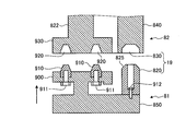
- the swing arm lock mechanism 19 includes an arm lock pin 820 that is a second lock pin that is connected and fixed to the primary power transmission member 81 on the base 6 side above the air cylinder 83. And an arm lock hole 830 provided in an arm forming member 840 fixedly provided on the revolving arm 11 side.
- the arm lock pin 820 is lifted and lowered by the air cylinder 83 (see FIG. 4) together with the engagement plate 900 from which the engagement pins 910 and 910 protrude. It protrudes from the member 850.
- the engaging plate 900 on the base 6 side and the engaged plate 930 on the swivel arm 11 side are separated from each other.
- the air cylinder 83 is activated to raise the engagement plate 900 together with the elevating member 850, and as shown in FIG. , 910 are engaged with and engaged with the engagement holes 920 and 920.
- reference numeral 911 indicates a bolt for connecting and fixing the engagement pin 910 to the engagement plate 900
- reference numeral 912 indicates a bolt for connecting and fixing the lock pin 820 to the elevating member 850.
- the arm lock pin 820 is formed of a single large pin having a diameter larger than that of the engagement pin 910 and having a tapered surface 825 formed at the tip.
- the tapered surface 825 is formed at the tip of the arm lock pin 820, centering, that is, centering with respect to the arm lock hole 830 is facilitated, and there is a slight amount between the arm lock pin 820 and the arm lock hole 830. Even if there is a misalignment, the arm lock pin 820 is easily fitted into the arm lock hole 830.
- the transport device 1 includes a rotation lock mechanism 10 that prohibits rotation except when the turntable 12 is located at the work position 40.
- the rotation lock mechanism 10 according to the present embodiment is in a position that does not appear in FIGS. 4, 5 ⁇ / b> A, and 5 ⁇ / b> B, as shown in FIGS. 6A and 6B, the rotation lock mechanism 10 is not connected to the engagement plate 900 and the engaged plate 930. It is provided in between.
- the rotation lock mechanism 10 includes a rotation lock hole 14 provided in a penetrating manner in an engaged plate 930 in which engagement holes 920 and 920 are formed as members on the revolving arm 11 side.
- a rotation lock pin 15 that engages with the rotation lock hole 14 when the turntable 12 is positioned at the work position 41 is provided.
- the rotation lock hole 14 functions as a first lock hole
- the rotation lock pin 15 functions as a first lock pin
- the rotation lock pin 15 protrudes downward at a position corresponding to the rotation lock hole 14 on the distal end side of the bowl-shaped piece body 152 biased downward by the spring 151. Although not shown, the rotation lock pin 15 is detachably connected to the bowl-shaped piece body 152 with a bolt.
- the bowl-shaped piece body 152 is arranged to be movable up and down in a state where a guide key formed on the back part is loosely fitted in a guide key groove 153 formed on the inner wall of the arm case 110.
- the engaging plate 900 is provided with a convex portion 950 for extracting the rotation lock pin 15 from the rotation lock hole 14. That is, when the engagement plate 900 is raised by driving the air cylinder 83, the upper end of the convex portion 950 comes into contact with the lower end of the bowl-shaped piece body 152. When the engagement plate 900 is raised in this state, the bowl-shaped piece body 152 rises and rotates. Thus, the rotation lock pin 15 inserted into 14 is detached from the rotation lock hole 14.
- the engaged plate 930 is not allowed to rotate, and the rotation of the turntable 12 is prohibited including the case where the turntable 12 is located in the loading / unloading position 40 except when located at the work position 41.
- the turntable 12 does not rotate naturally or by an external force.
- the air cylinder 83 operates to raise the engagement plate 900 together with the elevating member 850.
- the engagement plate 900 is raised, as shown in FIG. 6B, the engagement pins 910 and 910 are fitted into the engagement holes 920 and 920, and at the same time, the convex portion 950 resists the spring 151 and moves the bowl-shaped piece body 152.
- the rotation lock pin 15 is lifted and removed from the rotation lock hole 14. Therefore, the turntable 12 rotates when power is transmitted from the table rotation motor 80.
- the turntable 12 is prohibited from rotating except when located at the work position 41, and is allowed to rotate only when located at the work position 41.
- the posture of the work 5 placed on the turntable 12 when it is at the loading / unloading position 40 does not deviate azimuthally even if it is transported to the work position 41, and work reliability when performing precise work. Becomes higher.
- the engagement / disengagement operation of the rotation lock pin 15 with respect to the rotation lock hole 14 in the rotation lock mechanism 10 and the engagement / disengagement operation with respect to the arm lock hole 830 of the arm lock pin 820 in the swing arm lock mechanism 19 are the actuators of the clutch mechanism 9. This is linked to the operation of a certain air cylinder 83.
- the secondary side power transmission member 82 that transmits to the turntable 12 positioned at 41 is provided, and the rotation lock hole 14 and the arm lock hole 830 of the rotation lock mechanism 10 are connected to the secondary side power transmission member 82. It is because it provided in the member which comprises.
- an engagement hole 920 is provided in the secondary side power transmission member 82, and an engagement pin 910 that is detachable with respect to the engagement hole 920 is provided in the primary side power transmission member 81.
- An air cylinder 83 is provided in the vicinity of the primary side power transmission member 81 as an actuator for reciprocating the engagement pin 910. Therefore, the structure of the conveying apparatus 1 is also compact.
- the rotation lock pin 15, the engagement pin 920, and the arm lock pin 820 in this embodiment are the metal which forms the secondary side power transmission member 82, and, in this case, the to-be-engaged member 930 provided in the turning arm 11 side. Further, it is made of a metal softer than the arm forming member 840.
- the engaged member 930 and the arm forming member 840 are formed of steel or the like, while the rotation lock pin 15, the engagement pin 920, and the arm lock pin 820 are formed of a copper alloy.
- the rotation lock pin 15, the engagement pin 920, the arm lock pin 820, etc. may be appropriately replaced if worn. For this purpose, they are detachably connected.
- tapered surface 825 is formed at the tip of the arm lock pin 820, in order to facilitate centering, in the present embodiment, not only the arm lock pin 820 but also the above-mentioned.
- the engagement pin 910 and the rotation lock pin 15 are also tapered.
- the robot system 3 may be any combination of the work robot 2 that performs not only the painting work but also the predetermined work and the transport apparatus 1 having the above-described configuration.
- the transfer device 1 is attached to the swivel arm 11 through which the tip part turns while turning at the carry-in / out position 40 and the work position 41 provided in advance on the circular track, and the tip of the swivel arm 11.
- a turntable 12 that revolves along a circular track and that can rotate in the horizontal direction with the workpiece 5 placed at the mounting position, and rotation that prohibits rotation except when the turntable 12 is positioned at the work position 41.
- the lock mechanism 10 is provided.
- the work robot 2 is mounted on the upper part of the transfer device 1, but the arrangement of the work robot 2 is not limited to the above-described embodiment.
- the transfer device 1 and the work robot 2 can be installed separately.
- the work robot 2 is disposed in the vicinity of the ceiling 44 of the work booth 4, and the robot arm 22 is extended downward to perform the painting work.
- the transfer device 1 and the work robot 2 are arranged in parallel at a predetermined interval in the work booth 4 in a direction orthogonal to the direction connecting the loading / unloading position 40 and the work position 41. Is.
Abstract
Priority Applications (5)
| Application Number | Priority Date | Filing Date | Title |
|---|---|---|---|
| PCT/JP2011/069639 WO2013030958A1 (fr) | 2011-08-30 | 2011-08-30 | Système de robot et de dispositif de transport |
| JP2013530939A JP6044542B2 (ja) | 2011-08-30 | 2011-08-30 | 搬送装置およびロボットシステム |
| EP11871618.2A EP2752379A4 (fr) | 2011-08-30 | 2011-08-30 | Système de robot et de dispositif de transport |
| CN201180073210.8A CN103764527B (zh) | 2011-08-30 | 2011-08-30 | 搬运装置及机器人系统 |
| US14/188,690 US20140165907A1 (en) | 2011-08-30 | 2014-02-25 | Conveyance apparatus and robot system |
Applications Claiming Priority (1)
| Application Number | Priority Date | Filing Date | Title |
|---|---|---|---|
| PCT/JP2011/069639 WO2013030958A1 (fr) | 2011-08-30 | 2011-08-30 | Système de robot et de dispositif de transport |
Related Child Applications (1)
| Application Number | Title | Priority Date | Filing Date |
|---|---|---|---|
| US14/188,690 Continuation US20140165907A1 (en) | 2011-08-30 | 2014-02-25 | Conveyance apparatus and robot system |
Publications (1)
| Publication Number | Publication Date |
|---|---|
| WO2013030958A1 true WO2013030958A1 (fr) | 2013-03-07 |
Family
ID=47755511
Family Applications (1)
| Application Number | Title | Priority Date | Filing Date |
|---|---|---|---|
| PCT/JP2011/069639 WO2013030958A1 (fr) | 2011-08-30 | 2011-08-30 | Système de robot et de dispositif de transport |
Country Status (5)
| Country | Link |
|---|---|
| US (1) | US20140165907A1 (fr) |
| EP (1) | EP2752379A4 (fr) |
| JP (1) | JP6044542B2 (fr) |
| CN (1) | CN103764527B (fr) |
| WO (1) | WO2013030958A1 (fr) |
Cited By (8)
| Publication number | Priority date | Publication date | Assignee | Title |
|---|---|---|---|---|
| ITBO20130124A1 (it) * | 2013-03-22 | 2014-09-23 | Siti B & T Group S P A Con Socio U Nico | Impianto per il trattamento, in particolare la smaltatura, di sanitari |
| US20150158136A1 (en) * | 2013-12-11 | 2015-06-11 | Unimetrik, S.A. | Indexing head with two rotating axes |
| EP2886263A1 (fr) * | 2013-12-20 | 2015-06-24 | Getting Robotika S.L. | Installation robotisée |
| JP2017043477A (ja) * | 2015-08-28 | 2017-03-02 | 株式会社ダイフク | 加工設備及び加工方法 |
| JP2019514712A (ja) * | 2016-04-27 | 2019-06-06 | オバロ ゲーエムベーハー | プログラミング可能な運動自動装置のための電動継手 |
| US10675754B2 (en) | 2017-02-06 | 2020-06-09 | Seiko Epson Corporation | Robot system |
| CN112439590A (zh) * | 2020-11-15 | 2021-03-05 | 泰州市津达电子科技有限公司 | 一种变压器生产用表面喷粉设备 |
| CN112547370A (zh) * | 2020-11-27 | 2021-03-26 | 中铁建工集团山东有限公司 | 一种节能环保的建筑施工用板材喷漆装置 |
Families Citing this family (11)
| Publication number | Priority date | Publication date | Assignee | Title |
|---|---|---|---|---|
| CN104444330A (zh) * | 2014-12-05 | 2015-03-25 | 江苏惠宇机械制造有限公司 | 一种回转定位机构 |
| CN105363606B (zh) * | 2015-12-15 | 2019-04-23 | 佛山沃顿装备技术股份有限公司 | 一种自动喷漆机器人 |
| JP6737726B2 (ja) * | 2017-03-02 | 2020-08-12 | オークマ株式会社 | 工作機械 |
| IT201700025799A1 (it) * | 2017-03-08 | 2018-09-08 | Epistolio S R L | Gruppo di verniciatura |
| IT201700025766A1 (it) * | 2017-03-08 | 2018-09-08 | Epistolio S R L | Robot di verniciatura |
| CN109290113B (zh) * | 2018-11-29 | 2024-04-09 | 三威塑胶制品(珠海)有限公司 | 一种可平喷的喷涂装置和喷涂生产线 |
| GB2580943B (en) * | 2019-01-31 | 2021-11-03 | Arrival Ltd | Mobile robots having mechanical and data coupling mechanisms |
| CN110125959A (zh) * | 2019-05-27 | 2019-08-16 | 四川宏华石油设备有限公司 | 一种夹持装置 |
| JP7136067B2 (ja) * | 2019-11-27 | 2022-09-13 | 株式会社安川電機 | ロボットシステム |
| JP2021174949A (ja) * | 2020-04-30 | 2021-11-01 | 日本電産サンキョー株式会社 | 搬送システム |
| CN114074043A (zh) * | 2020-08-21 | 2022-02-22 | 泰科电子(上海)有限公司 | 喷漆系统 |
Citations (3)
| Publication number | Priority date | Publication date | Assignee | Title |
|---|---|---|---|---|
| JPH01196506A (ja) * | 1988-02-01 | 1989-08-08 | Shin Meiwa Ind Co Ltd | ロボット用ティーチング装置 |
| JPH11188597A (ja) * | 1997-12-26 | 1999-07-13 | Kansai Giken:Kk | グラインダ、そのチェンジャー機構及び供給受取機構 |
| JP4190631B2 (ja) | 1998-11-25 | 2008-12-03 | 川崎重工業株式会社 | 搬送装置 |
Family Cites Families (8)
| Publication number | Priority date | Publication date | Assignee | Title |
|---|---|---|---|---|
| US2110755A (en) * | 1933-02-07 | 1938-03-08 | Gillord Corp | Method and apparatus for applying metal coatings |
| US3142941A (en) * | 1962-10-03 | 1964-08-04 | Norton Co | Grinding machine |
| JPS5742364A (en) * | 1980-08-23 | 1982-03-09 | Tenshiyou Denki Kogyo Kk | Method and apparatus for automatic coating |
| GB2105234A (en) * | 1981-09-08 | 1983-03-23 | Lansing Bagnall Ltd | Work support including positionable work-tables |
| US4764077A (en) * | 1986-04-18 | 1988-08-16 | Thermwood Corporation | Assembly for performing work functions on a workpiece |
| JP2974871B2 (ja) * | 1993-03-31 | 1999-11-10 | 日本碍子株式会社 | 円筒状ワークの内周面溶射被膜自動形成システム |
| JP5044138B2 (ja) * | 2006-04-17 | 2012-10-10 | 川崎重工業株式会社 | 搬送システムおよび加工設備 |
| JP2008221098A (ja) * | 2007-03-12 | 2008-09-25 | Ichikawa Koken:Kk | 自動塗装装置及び塗装ブース |
-
2011
- 2011-08-30 JP JP2013530939A patent/JP6044542B2/ja active Active
- 2011-08-30 WO PCT/JP2011/069639 patent/WO2013030958A1/fr active Application Filing
- 2011-08-30 EP EP11871618.2A patent/EP2752379A4/fr not_active Withdrawn
- 2011-08-30 CN CN201180073210.8A patent/CN103764527B/zh not_active Expired - Fee Related
-
2014
- 2014-02-25 US US14/188,690 patent/US20140165907A1/en not_active Abandoned
Patent Citations (3)
| Publication number | Priority date | Publication date | Assignee | Title |
|---|---|---|---|---|
| JPH01196506A (ja) * | 1988-02-01 | 1989-08-08 | Shin Meiwa Ind Co Ltd | ロボット用ティーチング装置 |
| JPH11188597A (ja) * | 1997-12-26 | 1999-07-13 | Kansai Giken:Kk | グラインダ、そのチェンジャー機構及び供給受取機構 |
| JP4190631B2 (ja) | 1998-11-25 | 2008-12-03 | 川崎重工業株式会社 | 搬送装置 |
Non-Patent Citations (1)
| Title |
|---|
| See also references of EP2752379A4 * |
Cited By (9)
| Publication number | Priority date | Publication date | Assignee | Title |
|---|---|---|---|---|
| ITBO20130124A1 (it) * | 2013-03-22 | 2014-09-23 | Siti B & T Group S P A Con Socio U Nico | Impianto per il trattamento, in particolare la smaltatura, di sanitari |
| US20150158136A1 (en) * | 2013-12-11 | 2015-06-11 | Unimetrik, S.A. | Indexing head with two rotating axes |
| US9958249B2 (en) * | 2013-12-11 | 2018-05-01 | Unimetrik, S.A. | Indexing head with two rotating axes |
| EP2886263A1 (fr) * | 2013-12-20 | 2015-06-24 | Getting Robotika S.L. | Installation robotisée |
| JP2017043477A (ja) * | 2015-08-28 | 2017-03-02 | 株式会社ダイフク | 加工設備及び加工方法 |
| JP2019514712A (ja) * | 2016-04-27 | 2019-06-06 | オバロ ゲーエムベーハー | プログラミング可能な運動自動装置のための電動継手 |
| US10675754B2 (en) | 2017-02-06 | 2020-06-09 | Seiko Epson Corporation | Robot system |
| CN112439590A (zh) * | 2020-11-15 | 2021-03-05 | 泰州市津达电子科技有限公司 | 一种变压器生产用表面喷粉设备 |
| CN112547370A (zh) * | 2020-11-27 | 2021-03-26 | 中铁建工集团山东有限公司 | 一种节能环保的建筑施工用板材喷漆装置 |
Also Published As
| Publication number | Publication date |
|---|---|
| JPWO2013030958A1 (ja) | 2015-03-23 |
| CN103764527A (zh) | 2014-04-30 |
| EP2752379A1 (fr) | 2014-07-09 |
| EP2752379A4 (fr) | 2015-09-02 |
| US20140165907A1 (en) | 2014-06-19 |
| JP6044542B2 (ja) | 2016-12-14 |
| CN103764527B (zh) | 2016-04-13 |
Similar Documents
| Publication | Publication Date | Title |
|---|---|---|
| JP6044542B2 (ja) | 搬送装置およびロボットシステム | |
| KR101587311B1 (ko) | 반송 장치 및 로봇 시스템 | |
| CN103240591B (zh) | 装配设备和装配方法 | |
| JP5549702B2 (ja) | 搬送装置およびロボットシステム | |
| TWI473695B (zh) | 機器人臂部件 | |
| US8231117B2 (en) | Robot system | |
| CN114029864B (zh) | 一种喷丸-磨抛一体化加工末端执行器及其控制方法 | |
| JP6528607B2 (ja) | 加工設備及び加工方法 | |
| TW201700240A (zh) | 電器機器安裝裝置及方法 | |
| US10843349B2 (en) | Conveyance device | |
| JP2020049549A (ja) | ロボットユニット | |
| TW531465B (en) | A machine tool head, a machine tool and a method for working an object | |
| JP2000159338A (ja) | 搬送装置 | |
| JP2011020232A (ja) | 被塗装物保持ロボットおよび塗装用ロボットシステム | |
| JP2012086121A (ja) | ワーク供給装置 | |
| CN219540656U (zh) | 便于喷涂背面的喷涂装置 | |
| JP5790590B2 (ja) | ワーク搬送装置 | |
| KR20210009998A (ko) | 워크탑재 반송장치를 활용한 로봇시스템 | |
| CN113290579A (zh) | 一种用于暗环境机械手臂检修的光源固定且角度可调装置 | |
| KR20160122293A (ko) | 손목장치 및 이를 포함하는 케이블 내장형 로봇 | |
| KR20150133393A (ko) | 도장로봇용 케이블 가이드장치 및 이를 포함하는 도장로봇 | |
| JP4978228B2 (ja) | ワーク給排装置 | |
| JP2009039793A (ja) | ワーク加工設備 |
Legal Events
| Date | Code | Title | Description |
|---|---|---|---|
| 121 | Ep: the epo has been informed by wipo that ep was designated in this application |
Ref document number: 11871618 Country of ref document: EP Kind code of ref document: A1 |
|
| ENP | Entry into the national phase |
Ref document number: 2013530939 Country of ref document: JP Kind code of ref document: A |
|
| REEP | Request for entry into the european phase |
Ref document number: 2011871618 Country of ref document: EP |
|
| WWE | Wipo information: entry into national phase |
Ref document number: 2011871618 Country of ref document: EP |
|
| NENP | Non-entry into the national phase |
Ref country code: DE |