WO2013018221A1 - 車両および車両の制御方法 - Google Patents
車両および車両の制御方法 Download PDFInfo
- Publication number
- WO2013018221A1 WO2013018221A1 PCT/JP2011/067840 JP2011067840W WO2013018221A1 WO 2013018221 A1 WO2013018221 A1 WO 2013018221A1 JP 2011067840 W JP2011067840 W JP 2011067840W WO 2013018221 A1 WO2013018221 A1 WO 2013018221A1
- Authority
- WO
- WIPO (PCT)
- Prior art keywords
- power
- voltage
- internal combustion
- battery
- combustion engine
- Prior art date
Links
Images


Classifications
-
- B—PERFORMING OPERATIONS; TRANSPORTING
- B60—VEHICLES IN GENERAL
- B60W—CONJOINT CONTROL OF VEHICLE SUB-UNITS OF DIFFERENT TYPE OR DIFFERENT FUNCTION; CONTROL SYSTEMS SPECIALLY ADAPTED FOR HYBRID VEHICLES; ROAD VEHICLE DRIVE CONTROL SYSTEMS FOR PURPOSES NOT RELATED TO THE CONTROL OF A PARTICULAR SUB-UNIT
- B60W10/00—Conjoint control of vehicle sub-units of different type or different function
- B60W10/04—Conjoint control of vehicle sub-units of different type or different function including control of propulsion units
- B60W10/06—Conjoint control of vehicle sub-units of different type or different function including control of propulsion units including control of combustion engines
-
- B—PERFORMING OPERATIONS; TRANSPORTING
- B60—VEHICLES IN GENERAL
- B60K—ARRANGEMENT OR MOUNTING OF PROPULSION UNITS OR OF TRANSMISSIONS IN VEHICLES; ARRANGEMENT OR MOUNTING OF PLURAL DIVERSE PRIME-MOVERS IN VEHICLES; AUXILIARY DRIVES FOR VEHICLES; INSTRUMENTATION OR DASHBOARDS FOR VEHICLES; ARRANGEMENTS IN CONNECTION WITH COOLING, AIR INTAKE, GAS EXHAUST OR FUEL SUPPLY OF PROPULSION UNITS IN VEHICLES
- B60K6/00—Arrangement or mounting of plural diverse prime-movers for mutual or common propulsion, e.g. hybrid propulsion systems comprising electric motors and internal combustion engines ; Control systems therefor, i.e. systems controlling two or more prime movers, or controlling one of these prime movers and any of the transmission, drive or drive units Informative references: mechanical gearings with secondary electric drive F16H3/72; arrangements for handling mechanical energy structurally associated with the dynamo-electric machine H02K7/00; machines comprising structurally interrelated motor and generator parts H02K51/00; dynamo-electric machines not otherwise provided for in H02K see H02K99/00
- B60K6/20—Arrangement or mounting of plural diverse prime-movers for mutual or common propulsion, e.g. hybrid propulsion systems comprising electric motors and internal combustion engines ; Control systems therefor, i.e. systems controlling two or more prime movers, or controlling one of these prime movers and any of the transmission, drive or drive units Informative references: mechanical gearings with secondary electric drive F16H3/72; arrangements for handling mechanical energy structurally associated with the dynamo-electric machine H02K7/00; machines comprising structurally interrelated motor and generator parts H02K51/00; dynamo-electric machines not otherwise provided for in H02K see H02K99/00 the prime-movers consisting of electric motors and internal combustion engines, e.g. HEVs
- B60K6/42—Arrangement or mounting of plural diverse prime-movers for mutual or common propulsion, e.g. hybrid propulsion systems comprising electric motors and internal combustion engines ; Control systems therefor, i.e. systems controlling two or more prime movers, or controlling one of these prime movers and any of the transmission, drive or drive units Informative references: mechanical gearings with secondary electric drive F16H3/72; arrangements for handling mechanical energy structurally associated with the dynamo-electric machine H02K7/00; machines comprising structurally interrelated motor and generator parts H02K51/00; dynamo-electric machines not otherwise provided for in H02K see H02K99/00 the prime-movers consisting of electric motors and internal combustion engines, e.g. HEVs characterised by the architecture of the hybrid electric vehicle
- B60K6/44—Series-parallel type
- B60K6/445—Differential gearing distribution type
-
- B—PERFORMING OPERATIONS; TRANSPORTING
- B60—VEHICLES IN GENERAL
- B60L—PROPULSION OF ELECTRICALLY-PROPELLED VEHICLES; SUPPLYING ELECTRIC POWER FOR AUXILIARY EQUIPMENT OF ELECTRICALLY-PROPELLED VEHICLES; ELECTRODYNAMIC BRAKE SYSTEMS FOR VEHICLES IN GENERAL; MAGNETIC SUSPENSION OR LEVITATION FOR VEHICLES; MONITORING OPERATING VARIABLES OF ELECTRICALLY-PROPELLED VEHICLES; ELECTRIC SAFETY DEVICES FOR ELECTRICALLY-PROPELLED VEHICLES
- B60L1/00—Supplying electric power to auxiliary equipment of vehicles
- B60L1/003—Supplying electric power to auxiliary equipment of vehicles to auxiliary motors, e.g. for pumps, compressors
-
- B—PERFORMING OPERATIONS; TRANSPORTING
- B60—VEHICLES IN GENERAL
- B60L—PROPULSION OF ELECTRICALLY-PROPELLED VEHICLES; SUPPLYING ELECTRIC POWER FOR AUXILIARY EQUIPMENT OF ELECTRICALLY-PROPELLED VEHICLES; ELECTRODYNAMIC BRAKE SYSTEMS FOR VEHICLES IN GENERAL; MAGNETIC SUSPENSION OR LEVITATION FOR VEHICLES; MONITORING OPERATING VARIABLES OF ELECTRICALLY-PROPELLED VEHICLES; ELECTRIC SAFETY DEVICES FOR ELECTRICALLY-PROPELLED VEHICLES
- B60L1/00—Supplying electric power to auxiliary equipment of vehicles
- B60L1/14—Supplying electric power to auxiliary equipment of vehicles to electric lighting circuits
-
- B—PERFORMING OPERATIONS; TRANSPORTING
- B60—VEHICLES IN GENERAL
- B60L—PROPULSION OF ELECTRICALLY-PROPELLED VEHICLES; SUPPLYING ELECTRIC POWER FOR AUXILIARY EQUIPMENT OF ELECTRICALLY-PROPELLED VEHICLES; ELECTRODYNAMIC BRAKE SYSTEMS FOR VEHICLES IN GENERAL; MAGNETIC SUSPENSION OR LEVITATION FOR VEHICLES; MONITORING OPERATING VARIABLES OF ELECTRICALLY-PROPELLED VEHICLES; ELECTRIC SAFETY DEVICES FOR ELECTRICALLY-PROPELLED VEHICLES
- B60L15/00—Methods, circuits, or devices for controlling the traction-motor speed of electrically-propelled vehicles
- B60L15/20—Methods, circuits, or devices for controlling the traction-motor speed of electrically-propelled vehicles for control of the vehicle or its driving motor to achieve a desired performance, e.g. speed, torque, programmed variation of speed
- B60L15/2009—Methods, circuits, or devices for controlling the traction-motor speed of electrically-propelled vehicles for control of the vehicle or its driving motor to achieve a desired performance, e.g. speed, torque, programmed variation of speed for braking
-
- B—PERFORMING OPERATIONS; TRANSPORTING
- B60—VEHICLES IN GENERAL
- B60L—PROPULSION OF ELECTRICALLY-PROPELLED VEHICLES; SUPPLYING ELECTRIC POWER FOR AUXILIARY EQUIPMENT OF ELECTRICALLY-PROPELLED VEHICLES; ELECTRODYNAMIC BRAKE SYSTEMS FOR VEHICLES IN GENERAL; MAGNETIC SUSPENSION OR LEVITATION FOR VEHICLES; MONITORING OPERATING VARIABLES OF ELECTRICALLY-PROPELLED VEHICLES; ELECTRIC SAFETY DEVICES FOR ELECTRICALLY-PROPELLED VEHICLES
- B60L15/00—Methods, circuits, or devices for controlling the traction-motor speed of electrically-propelled vehicles
- B60L15/20—Methods, circuits, or devices for controlling the traction-motor speed of electrically-propelled vehicles for control of the vehicle or its driving motor to achieve a desired performance, e.g. speed, torque, programmed variation of speed
- B60L15/2054—Methods, circuits, or devices for controlling the traction-motor speed of electrically-propelled vehicles for control of the vehicle or its driving motor to achieve a desired performance, e.g. speed, torque, programmed variation of speed by controlling transmissions or clutches
-
- B—PERFORMING OPERATIONS; TRANSPORTING
- B60—VEHICLES IN GENERAL
- B60L—PROPULSION OF ELECTRICALLY-PROPELLED VEHICLES; SUPPLYING ELECTRIC POWER FOR AUXILIARY EQUIPMENT OF ELECTRICALLY-PROPELLED VEHICLES; ELECTRODYNAMIC BRAKE SYSTEMS FOR VEHICLES IN GENERAL; MAGNETIC SUSPENSION OR LEVITATION FOR VEHICLES; MONITORING OPERATING VARIABLES OF ELECTRICALLY-PROPELLED VEHICLES; ELECTRIC SAFETY DEVICES FOR ELECTRICALLY-PROPELLED VEHICLES
- B60L3/00—Electric devices on electrically-propelled vehicles for safety purposes; Monitoring operating variables, e.g. speed, deceleration or energy consumption
- B60L3/0023—Detecting, eliminating, remedying or compensating for drive train abnormalities, e.g. failures within the drive train
- B60L3/0046—Detecting, eliminating, remedying or compensating for drive train abnormalities, e.g. failures within the drive train relating to electric energy storage systems, e.g. batteries or capacitors
-
- B—PERFORMING OPERATIONS; TRANSPORTING
- B60—VEHICLES IN GENERAL
- B60L—PROPULSION OF ELECTRICALLY-PROPELLED VEHICLES; SUPPLYING ELECTRIC POWER FOR AUXILIARY EQUIPMENT OF ELECTRICALLY-PROPELLED VEHICLES; ELECTRODYNAMIC BRAKE SYSTEMS FOR VEHICLES IN GENERAL; MAGNETIC SUSPENSION OR LEVITATION FOR VEHICLES; MONITORING OPERATING VARIABLES OF ELECTRICALLY-PROPELLED VEHICLES; ELECTRIC SAFETY DEVICES FOR ELECTRICALLY-PROPELLED VEHICLES
- B60L50/00—Electric propulsion with power supplied within the vehicle
- B60L50/10—Electric propulsion with power supplied within the vehicle using propulsion power supplied by engine-driven generators, e.g. generators driven by combustion engines
- B60L50/16—Electric propulsion with power supplied within the vehicle using propulsion power supplied by engine-driven generators, e.g. generators driven by combustion engines with provision for separate direct mechanical propulsion
-
- B—PERFORMING OPERATIONS; TRANSPORTING
- B60—VEHICLES IN GENERAL
- B60L—PROPULSION OF ELECTRICALLY-PROPELLED VEHICLES; SUPPLYING ELECTRIC POWER FOR AUXILIARY EQUIPMENT OF ELECTRICALLY-PROPELLED VEHICLES; ELECTRODYNAMIC BRAKE SYSTEMS FOR VEHICLES IN GENERAL; MAGNETIC SUSPENSION OR LEVITATION FOR VEHICLES; MONITORING OPERATING VARIABLES OF ELECTRICALLY-PROPELLED VEHICLES; ELECTRIC SAFETY DEVICES FOR ELECTRICALLY-PROPELLED VEHICLES
- B60L50/00—Electric propulsion with power supplied within the vehicle
- B60L50/50—Electric propulsion with power supplied within the vehicle using propulsion power supplied by batteries or fuel cells
- B60L50/60—Electric propulsion with power supplied within the vehicle using propulsion power supplied by batteries or fuel cells using power supplied by batteries
- B60L50/61—Electric propulsion with power supplied within the vehicle using propulsion power supplied by batteries or fuel cells using power supplied by batteries by batteries charged by engine-driven generators, e.g. series hybrid electric vehicles
-
- B—PERFORMING OPERATIONS; TRANSPORTING
- B60—VEHICLES IN GENERAL
- B60L—PROPULSION OF ELECTRICALLY-PROPELLED VEHICLES; SUPPLYING ELECTRIC POWER FOR AUXILIARY EQUIPMENT OF ELECTRICALLY-PROPELLED VEHICLES; ELECTRODYNAMIC BRAKE SYSTEMS FOR VEHICLES IN GENERAL; MAGNETIC SUSPENSION OR LEVITATION FOR VEHICLES; MONITORING OPERATING VARIABLES OF ELECTRICALLY-PROPELLED VEHICLES; ELECTRIC SAFETY DEVICES FOR ELECTRICALLY-PROPELLED VEHICLES
- B60L58/00—Methods or circuit arrangements for monitoring or controlling batteries or fuel cells, specially adapted for electric vehicles
- B60L58/10—Methods or circuit arrangements for monitoring or controlling batteries or fuel cells, specially adapted for electric vehicles for monitoring or controlling batteries
- B60L58/12—Methods or circuit arrangements for monitoring or controlling batteries or fuel cells, specially adapted for electric vehicles for monitoring or controlling batteries responding to state of charge [SoC]
- B60L58/14—Preventing excessive discharging
-
- B—PERFORMING OPERATIONS; TRANSPORTING
- B60—VEHICLES IN GENERAL
- B60L—PROPULSION OF ELECTRICALLY-PROPELLED VEHICLES; SUPPLYING ELECTRIC POWER FOR AUXILIARY EQUIPMENT OF ELECTRICALLY-PROPELLED VEHICLES; ELECTRODYNAMIC BRAKE SYSTEMS FOR VEHICLES IN GENERAL; MAGNETIC SUSPENSION OR LEVITATION FOR VEHICLES; MONITORING OPERATING VARIABLES OF ELECTRICALLY-PROPELLED VEHICLES; ELECTRIC SAFETY DEVICES FOR ELECTRICALLY-PROPELLED VEHICLES
- B60L58/00—Methods or circuit arrangements for monitoring or controlling batteries or fuel cells, specially adapted for electric vehicles
- B60L58/10—Methods or circuit arrangements for monitoring or controlling batteries or fuel cells, specially adapted for electric vehicles for monitoring or controlling batteries
- B60L58/18—Methods or circuit arrangements for monitoring or controlling batteries or fuel cells, specially adapted for electric vehicles for monitoring or controlling batteries of two or more battery modules
- B60L58/21—Methods or circuit arrangements for monitoring or controlling batteries or fuel cells, specially adapted for electric vehicles for monitoring or controlling batteries of two or more battery modules having the same nominal voltage
-
- B—PERFORMING OPERATIONS; TRANSPORTING
- B60—VEHICLES IN GENERAL
- B60L—PROPULSION OF ELECTRICALLY-PROPELLED VEHICLES; SUPPLYING ELECTRIC POWER FOR AUXILIARY EQUIPMENT OF ELECTRICALLY-PROPELLED VEHICLES; ELECTRODYNAMIC BRAKE SYSTEMS FOR VEHICLES IN GENERAL; MAGNETIC SUSPENSION OR LEVITATION FOR VEHICLES; MONITORING OPERATING VARIABLES OF ELECTRICALLY-PROPELLED VEHICLES; ELECTRIC SAFETY DEVICES FOR ELECTRICALLY-PROPELLED VEHICLES
- B60L58/00—Methods or circuit arrangements for monitoring or controlling batteries or fuel cells, specially adapted for electric vehicles
- B60L58/10—Methods or circuit arrangements for monitoring or controlling batteries or fuel cells, specially adapted for electric vehicles for monitoring or controlling batteries
- B60L58/24—Methods or circuit arrangements for monitoring or controlling batteries or fuel cells, specially adapted for electric vehicles for monitoring or controlling batteries for controlling the temperature of batteries
-
- B—PERFORMING OPERATIONS; TRANSPORTING
- B60—VEHICLES IN GENERAL
- B60L—PROPULSION OF ELECTRICALLY-PROPELLED VEHICLES; SUPPLYING ELECTRIC POWER FOR AUXILIARY EQUIPMENT OF ELECTRICALLY-PROPELLED VEHICLES; ELECTRODYNAMIC BRAKE SYSTEMS FOR VEHICLES IN GENERAL; MAGNETIC SUSPENSION OR LEVITATION FOR VEHICLES; MONITORING OPERATING VARIABLES OF ELECTRICALLY-PROPELLED VEHICLES; ELECTRIC SAFETY DEVICES FOR ELECTRICALLY-PROPELLED VEHICLES
- B60L7/00—Electrodynamic brake systems for vehicles in general
- B60L7/10—Dynamic electric regenerative braking
- B60L7/14—Dynamic electric regenerative braking for vehicles propelled by ac motors
-
- B—PERFORMING OPERATIONS; TRANSPORTING
- B60—VEHICLES IN GENERAL
- B60W—CONJOINT CONTROL OF VEHICLE SUB-UNITS OF DIFFERENT TYPE OR DIFFERENT FUNCTION; CONTROL SYSTEMS SPECIALLY ADAPTED FOR HYBRID VEHICLES; ROAD VEHICLE DRIVE CONTROL SYSTEMS FOR PURPOSES NOT RELATED TO THE CONTROL OF A PARTICULAR SUB-UNIT
- B60W10/00—Conjoint control of vehicle sub-units of different type or different function
- B60W10/04—Conjoint control of vehicle sub-units of different type or different function including control of propulsion units
- B60W10/08—Conjoint control of vehicle sub-units of different type or different function including control of propulsion units including control of electric propulsion units, e.g. motors or generators
-
- B—PERFORMING OPERATIONS; TRANSPORTING
- B60—VEHICLES IN GENERAL
- B60W—CONJOINT CONTROL OF VEHICLE SUB-UNITS OF DIFFERENT TYPE OR DIFFERENT FUNCTION; CONTROL SYSTEMS SPECIALLY ADAPTED FOR HYBRID VEHICLES; ROAD VEHICLE DRIVE CONTROL SYSTEMS FOR PURPOSES NOT RELATED TO THE CONTROL OF A PARTICULAR SUB-UNIT
- B60W10/00—Conjoint control of vehicle sub-units of different type or different function
- B60W10/24—Conjoint control of vehicle sub-units of different type or different function including control of energy storage means
- B60W10/26—Conjoint control of vehicle sub-units of different type or different function including control of energy storage means for electrical energy, e.g. batteries or capacitors
-
- B—PERFORMING OPERATIONS; TRANSPORTING
- B60—VEHICLES IN GENERAL
- B60W—CONJOINT CONTROL OF VEHICLE SUB-UNITS OF DIFFERENT TYPE OR DIFFERENT FUNCTION; CONTROL SYSTEMS SPECIALLY ADAPTED FOR HYBRID VEHICLES; ROAD VEHICLE DRIVE CONTROL SYSTEMS FOR PURPOSES NOT RELATED TO THE CONTROL OF A PARTICULAR SUB-UNIT
- B60W20/00—Control systems specially adapted for hybrid vehicles
- B60W20/10—Controlling the power contribution of each of the prime movers to meet required power demand
- B60W20/13—Controlling the power contribution of each of the prime movers to meet required power demand in order to stay within battery power input or output limits; in order to prevent overcharging or battery depletion
-
- F—MECHANICAL ENGINEERING; LIGHTING; HEATING; WEAPONS; BLASTING
- F02—COMBUSTION ENGINES; HOT-GAS OR COMBUSTION-PRODUCT ENGINE PLANTS
- F02N—STARTING OF COMBUSTION ENGINES; STARTING AIDS FOR SUCH ENGINES, NOT OTHERWISE PROVIDED FOR
- F02N11/00—Starting of engines by means of electric motors
- F02N11/08—Circuits or control means specially adapted for starting of engines
- F02N11/0862—Circuits or control means specially adapted for starting of engines characterised by the electrical power supply means, e.g. battery
-
- B—PERFORMING OPERATIONS; TRANSPORTING
- B60—VEHICLES IN GENERAL
- B60K—ARRANGEMENT OR MOUNTING OF PROPULSION UNITS OR OF TRANSMISSIONS IN VEHICLES; ARRANGEMENT OR MOUNTING OF PLURAL DIVERSE PRIME-MOVERS IN VEHICLES; AUXILIARY DRIVES FOR VEHICLES; INSTRUMENTATION OR DASHBOARDS FOR VEHICLES; ARRANGEMENTS IN CONNECTION WITH COOLING, AIR INTAKE, GAS EXHAUST OR FUEL SUPPLY OF PROPULSION UNITS IN VEHICLES
- B60K6/00—Arrangement or mounting of plural diverse prime-movers for mutual or common propulsion, e.g. hybrid propulsion systems comprising electric motors and internal combustion engines ; Control systems therefor, i.e. systems controlling two or more prime movers, or controlling one of these prime movers and any of the transmission, drive or drive units Informative references: mechanical gearings with secondary electric drive F16H3/72; arrangements for handling mechanical energy structurally associated with the dynamo-electric machine H02K7/00; machines comprising structurally interrelated motor and generator parts H02K51/00; dynamo-electric machines not otherwise provided for in H02K see H02K99/00
- B60K6/20—Arrangement or mounting of plural diverse prime-movers for mutual or common propulsion, e.g. hybrid propulsion systems comprising electric motors and internal combustion engines ; Control systems therefor, i.e. systems controlling two or more prime movers, or controlling one of these prime movers and any of the transmission, drive or drive units Informative references: mechanical gearings with secondary electric drive F16H3/72; arrangements for handling mechanical energy structurally associated with the dynamo-electric machine H02K7/00; machines comprising structurally interrelated motor and generator parts H02K51/00; dynamo-electric machines not otherwise provided for in H02K see H02K99/00 the prime-movers consisting of electric motors and internal combustion engines, e.g. HEVs
- B60K6/22—Arrangement or mounting of plural diverse prime-movers for mutual or common propulsion, e.g. hybrid propulsion systems comprising electric motors and internal combustion engines ; Control systems therefor, i.e. systems controlling two or more prime movers, or controlling one of these prime movers and any of the transmission, drive or drive units Informative references: mechanical gearings with secondary electric drive F16H3/72; arrangements for handling mechanical energy structurally associated with the dynamo-electric machine H02K7/00; machines comprising structurally interrelated motor and generator parts H02K51/00; dynamo-electric machines not otherwise provided for in H02K see H02K99/00 the prime-movers consisting of electric motors and internal combustion engines, e.g. HEVs characterised by apparatus, components or means specially adapted for HEVs
- B60K6/26—Arrangement or mounting of plural diverse prime-movers for mutual or common propulsion, e.g. hybrid propulsion systems comprising electric motors and internal combustion engines ; Control systems therefor, i.e. systems controlling two or more prime movers, or controlling one of these prime movers and any of the transmission, drive or drive units Informative references: mechanical gearings with secondary electric drive F16H3/72; arrangements for handling mechanical energy structurally associated with the dynamo-electric machine H02K7/00; machines comprising structurally interrelated motor and generator parts H02K51/00; dynamo-electric machines not otherwise provided for in H02K see H02K99/00 the prime-movers consisting of electric motors and internal combustion engines, e.g. HEVs characterised by apparatus, components or means specially adapted for HEVs characterised by the motors or the generators
- B60K2006/268—Electric drive motor starts the engine, i.e. used as starter motor
-
- B—PERFORMING OPERATIONS; TRANSPORTING
- B60—VEHICLES IN GENERAL
- B60K—ARRANGEMENT OR MOUNTING OF PROPULSION UNITS OR OF TRANSMISSIONS IN VEHICLES; ARRANGEMENT OR MOUNTING OF PLURAL DIVERSE PRIME-MOVERS IN VEHICLES; AUXILIARY DRIVES FOR VEHICLES; INSTRUMENTATION OR DASHBOARDS FOR VEHICLES; ARRANGEMENTS IN CONNECTION WITH COOLING, AIR INTAKE, GAS EXHAUST OR FUEL SUPPLY OF PROPULSION UNITS IN VEHICLES
- B60K6/00—Arrangement or mounting of plural diverse prime-movers for mutual or common propulsion, e.g. hybrid propulsion systems comprising electric motors and internal combustion engines ; Control systems therefor, i.e. systems controlling two or more prime movers, or controlling one of these prime movers and any of the transmission, drive or drive units Informative references: mechanical gearings with secondary electric drive F16H3/72; arrangements for handling mechanical energy structurally associated with the dynamo-electric machine H02K7/00; machines comprising structurally interrelated motor and generator parts H02K51/00; dynamo-electric machines not otherwise provided for in H02K see H02K99/00
- B60K6/20—Arrangement or mounting of plural diverse prime-movers for mutual or common propulsion, e.g. hybrid propulsion systems comprising electric motors and internal combustion engines ; Control systems therefor, i.e. systems controlling two or more prime movers, or controlling one of these prime movers and any of the transmission, drive or drive units Informative references: mechanical gearings with secondary electric drive F16H3/72; arrangements for handling mechanical energy structurally associated with the dynamo-electric machine H02K7/00; machines comprising structurally interrelated motor and generator parts H02K51/00; dynamo-electric machines not otherwise provided for in H02K see H02K99/00 the prime-movers consisting of electric motors and internal combustion engines, e.g. HEVs
- B60K6/42—Arrangement or mounting of plural diverse prime-movers for mutual or common propulsion, e.g. hybrid propulsion systems comprising electric motors and internal combustion engines ; Control systems therefor, i.e. systems controlling two or more prime movers, or controlling one of these prime movers and any of the transmission, drive or drive units Informative references: mechanical gearings with secondary electric drive F16H3/72; arrangements for handling mechanical energy structurally associated with the dynamo-electric machine H02K7/00; machines comprising structurally interrelated motor and generator parts H02K51/00; dynamo-electric machines not otherwise provided for in H02K see H02K99/00 the prime-movers consisting of electric motors and internal combustion engines, e.g. HEVs characterised by the architecture of the hybrid electric vehicle
- B60K6/48—Parallel type
-
- B—PERFORMING OPERATIONS; TRANSPORTING
- B60—VEHICLES IN GENERAL
- B60L—PROPULSION OF ELECTRICALLY-PROPELLED VEHICLES; SUPPLYING ELECTRIC POWER FOR AUXILIARY EQUIPMENT OF ELECTRICALLY-PROPELLED VEHICLES; ELECTRODYNAMIC BRAKE SYSTEMS FOR VEHICLES IN GENERAL; MAGNETIC SUSPENSION OR LEVITATION FOR VEHICLES; MONITORING OPERATING VARIABLES OF ELECTRICALLY-PROPELLED VEHICLES; ELECTRIC SAFETY DEVICES FOR ELECTRICALLY-PROPELLED VEHICLES
- B60L2210/00—Converter types
- B60L2210/10—DC to DC converters
-
- B—PERFORMING OPERATIONS; TRANSPORTING
- B60—VEHICLES IN GENERAL
- B60L—PROPULSION OF ELECTRICALLY-PROPELLED VEHICLES; SUPPLYING ELECTRIC POWER FOR AUXILIARY EQUIPMENT OF ELECTRICALLY-PROPELLED VEHICLES; ELECTRODYNAMIC BRAKE SYSTEMS FOR VEHICLES IN GENERAL; MAGNETIC SUSPENSION OR LEVITATION FOR VEHICLES; MONITORING OPERATING VARIABLES OF ELECTRICALLY-PROPELLED VEHICLES; ELECTRIC SAFETY DEVICES FOR ELECTRICALLY-PROPELLED VEHICLES
- B60L2210/00—Converter types
- B60L2210/40—DC to AC converters
-
- B—PERFORMING OPERATIONS; TRANSPORTING
- B60—VEHICLES IN GENERAL
- B60L—PROPULSION OF ELECTRICALLY-PROPELLED VEHICLES; SUPPLYING ELECTRIC POWER FOR AUXILIARY EQUIPMENT OF ELECTRICALLY-PROPELLED VEHICLES; ELECTRODYNAMIC BRAKE SYSTEMS FOR VEHICLES IN GENERAL; MAGNETIC SUSPENSION OR LEVITATION FOR VEHICLES; MONITORING OPERATING VARIABLES OF ELECTRICALLY-PROPELLED VEHICLES; ELECTRIC SAFETY DEVICES FOR ELECTRICALLY-PROPELLED VEHICLES
- B60L2220/00—Electrical machine types; Structures or applications thereof
- B60L2220/10—Electrical machine types
- B60L2220/14—Synchronous machines
-
- B—PERFORMING OPERATIONS; TRANSPORTING
- B60—VEHICLES IN GENERAL
- B60L—PROPULSION OF ELECTRICALLY-PROPELLED VEHICLES; SUPPLYING ELECTRIC POWER FOR AUXILIARY EQUIPMENT OF ELECTRICALLY-PROPELLED VEHICLES; ELECTRODYNAMIC BRAKE SYSTEMS FOR VEHICLES IN GENERAL; MAGNETIC SUSPENSION OR LEVITATION FOR VEHICLES; MONITORING OPERATING VARIABLES OF ELECTRICALLY-PROPELLED VEHICLES; ELECTRIC SAFETY DEVICES FOR ELECTRICALLY-PROPELLED VEHICLES
- B60L2240/00—Control parameters of input or output; Target parameters
- B60L2240/10—Vehicle control parameters
- B60L2240/12—Speed
-
- B—PERFORMING OPERATIONS; TRANSPORTING
- B60—VEHICLES IN GENERAL
- B60L—PROPULSION OF ELECTRICALLY-PROPELLED VEHICLES; SUPPLYING ELECTRIC POWER FOR AUXILIARY EQUIPMENT OF ELECTRICALLY-PROPELLED VEHICLES; ELECTRODYNAMIC BRAKE SYSTEMS FOR VEHICLES IN GENERAL; MAGNETIC SUSPENSION OR LEVITATION FOR VEHICLES; MONITORING OPERATING VARIABLES OF ELECTRICALLY-PROPELLED VEHICLES; ELECTRIC SAFETY DEVICES FOR ELECTRICALLY-PROPELLED VEHICLES
- B60L2240/00—Control parameters of input or output; Target parameters
- B60L2240/10—Vehicle control parameters
- B60L2240/34—Cabin temperature
-
- B—PERFORMING OPERATIONS; TRANSPORTING
- B60—VEHICLES IN GENERAL
- B60L—PROPULSION OF ELECTRICALLY-PROPELLED VEHICLES; SUPPLYING ELECTRIC POWER FOR AUXILIARY EQUIPMENT OF ELECTRICALLY-PROPELLED VEHICLES; ELECTRODYNAMIC BRAKE SYSTEMS FOR VEHICLES IN GENERAL; MAGNETIC SUSPENSION OR LEVITATION FOR VEHICLES; MONITORING OPERATING VARIABLES OF ELECTRICALLY-PROPELLED VEHICLES; ELECTRIC SAFETY DEVICES FOR ELECTRICALLY-PROPELLED VEHICLES
- B60L2240/00—Control parameters of input or output; Target parameters
- B60L2240/40—Drive Train control parameters
- B60L2240/42—Drive Train control parameters related to electric machines
- B60L2240/421—Speed
-
- B—PERFORMING OPERATIONS; TRANSPORTING
- B60—VEHICLES IN GENERAL
- B60L—PROPULSION OF ELECTRICALLY-PROPELLED VEHICLES; SUPPLYING ELECTRIC POWER FOR AUXILIARY EQUIPMENT OF ELECTRICALLY-PROPELLED VEHICLES; ELECTRODYNAMIC BRAKE SYSTEMS FOR VEHICLES IN GENERAL; MAGNETIC SUSPENSION OR LEVITATION FOR VEHICLES; MONITORING OPERATING VARIABLES OF ELECTRICALLY-PROPELLED VEHICLES; ELECTRIC SAFETY DEVICES FOR ELECTRICALLY-PROPELLED VEHICLES
- B60L2240/00—Control parameters of input or output; Target parameters
- B60L2240/40—Drive Train control parameters
- B60L2240/42—Drive Train control parameters related to electric machines
- B60L2240/423—Torque
-
- B—PERFORMING OPERATIONS; TRANSPORTING
- B60—VEHICLES IN GENERAL
- B60L—PROPULSION OF ELECTRICALLY-PROPELLED VEHICLES; SUPPLYING ELECTRIC POWER FOR AUXILIARY EQUIPMENT OF ELECTRICALLY-PROPELLED VEHICLES; ELECTRODYNAMIC BRAKE SYSTEMS FOR VEHICLES IN GENERAL; MAGNETIC SUSPENSION OR LEVITATION FOR VEHICLES; MONITORING OPERATING VARIABLES OF ELECTRICALLY-PROPELLED VEHICLES; ELECTRIC SAFETY DEVICES FOR ELECTRICALLY-PROPELLED VEHICLES
- B60L2240/00—Control parameters of input or output; Target parameters
- B60L2240/40—Drive Train control parameters
- B60L2240/44—Drive Train control parameters related to combustion engines
- B60L2240/441—Speed
-
- B—PERFORMING OPERATIONS; TRANSPORTING
- B60—VEHICLES IN GENERAL
- B60L—PROPULSION OF ELECTRICALLY-PROPELLED VEHICLES; SUPPLYING ELECTRIC POWER FOR AUXILIARY EQUIPMENT OF ELECTRICALLY-PROPELLED VEHICLES; ELECTRODYNAMIC BRAKE SYSTEMS FOR VEHICLES IN GENERAL; MAGNETIC SUSPENSION OR LEVITATION FOR VEHICLES; MONITORING OPERATING VARIABLES OF ELECTRICALLY-PROPELLED VEHICLES; ELECTRIC SAFETY DEVICES FOR ELECTRICALLY-PROPELLED VEHICLES
- B60L2240/00—Control parameters of input or output; Target parameters
- B60L2240/40—Drive Train control parameters
- B60L2240/44—Drive Train control parameters related to combustion engines
- B60L2240/443—Torque
-
- B—PERFORMING OPERATIONS; TRANSPORTING
- B60—VEHICLES IN GENERAL
- B60L—PROPULSION OF ELECTRICALLY-PROPELLED VEHICLES; SUPPLYING ELECTRIC POWER FOR AUXILIARY EQUIPMENT OF ELECTRICALLY-PROPELLED VEHICLES; ELECTRODYNAMIC BRAKE SYSTEMS FOR VEHICLES IN GENERAL; MAGNETIC SUSPENSION OR LEVITATION FOR VEHICLES; MONITORING OPERATING VARIABLES OF ELECTRICALLY-PROPELLED VEHICLES; ELECTRIC SAFETY DEVICES FOR ELECTRICALLY-PROPELLED VEHICLES
- B60L2240/00—Control parameters of input or output; Target parameters
- B60L2240/40—Drive Train control parameters
- B60L2240/46—Drive Train control parameters related to wheels
- B60L2240/461—Speed
-
- B—PERFORMING OPERATIONS; TRANSPORTING
- B60—VEHICLES IN GENERAL
- B60L—PROPULSION OF ELECTRICALLY-PROPELLED VEHICLES; SUPPLYING ELECTRIC POWER FOR AUXILIARY EQUIPMENT OF ELECTRICALLY-PROPELLED VEHICLES; ELECTRODYNAMIC BRAKE SYSTEMS FOR VEHICLES IN GENERAL; MAGNETIC SUSPENSION OR LEVITATION FOR VEHICLES; MONITORING OPERATING VARIABLES OF ELECTRICALLY-PROPELLED VEHICLES; ELECTRIC SAFETY DEVICES FOR ELECTRICALLY-PROPELLED VEHICLES
- B60L2240/00—Control parameters of input or output; Target parameters
- B60L2240/40—Drive Train control parameters
- B60L2240/48—Drive Train control parameters related to transmissions
- B60L2240/486—Operating parameters
-
- B—PERFORMING OPERATIONS; TRANSPORTING
- B60—VEHICLES IN GENERAL
- B60L—PROPULSION OF ELECTRICALLY-PROPELLED VEHICLES; SUPPLYING ELECTRIC POWER FOR AUXILIARY EQUIPMENT OF ELECTRICALLY-PROPELLED VEHICLES; ELECTRODYNAMIC BRAKE SYSTEMS FOR VEHICLES IN GENERAL; MAGNETIC SUSPENSION OR LEVITATION FOR VEHICLES; MONITORING OPERATING VARIABLES OF ELECTRICALLY-PROPELLED VEHICLES; ELECTRIC SAFETY DEVICES FOR ELECTRICALLY-PROPELLED VEHICLES
- B60L2240/00—Control parameters of input or output; Target parameters
- B60L2240/40—Drive Train control parameters
- B60L2240/50—Drive Train control parameters related to clutches
- B60L2240/507—Operating parameters
-
- B—PERFORMING OPERATIONS; TRANSPORTING
- B60—VEHICLES IN GENERAL
- B60L—PROPULSION OF ELECTRICALLY-PROPELLED VEHICLES; SUPPLYING ELECTRIC POWER FOR AUXILIARY EQUIPMENT OF ELECTRICALLY-PROPELLED VEHICLES; ELECTRODYNAMIC BRAKE SYSTEMS FOR VEHICLES IN GENERAL; MAGNETIC SUSPENSION OR LEVITATION FOR VEHICLES; MONITORING OPERATING VARIABLES OF ELECTRICALLY-PROPELLED VEHICLES; ELECTRIC SAFETY DEVICES FOR ELECTRICALLY-PROPELLED VEHICLES
- B60L2240/00—Control parameters of input or output; Target parameters
- B60L2240/40—Drive Train control parameters
- B60L2240/52—Drive Train control parameters related to converters
- B60L2240/529—Current
-
- B—PERFORMING OPERATIONS; TRANSPORTING
- B60—VEHICLES IN GENERAL
- B60L—PROPULSION OF ELECTRICALLY-PROPELLED VEHICLES; SUPPLYING ELECTRIC POWER FOR AUXILIARY EQUIPMENT OF ELECTRICALLY-PROPELLED VEHICLES; ELECTRODYNAMIC BRAKE SYSTEMS FOR VEHICLES IN GENERAL; MAGNETIC SUSPENSION OR LEVITATION FOR VEHICLES; MONITORING OPERATING VARIABLES OF ELECTRICALLY-PROPELLED VEHICLES; ELECTRIC SAFETY DEVICES FOR ELECTRICALLY-PROPELLED VEHICLES
- B60L2240/00—Control parameters of input or output; Target parameters
- B60L2240/40—Drive Train control parameters
- B60L2240/54—Drive Train control parameters related to batteries
- B60L2240/545—Temperature
-
- B—PERFORMING OPERATIONS; TRANSPORTING
- B60—VEHICLES IN GENERAL
- B60L—PROPULSION OF ELECTRICALLY-PROPELLED VEHICLES; SUPPLYING ELECTRIC POWER FOR AUXILIARY EQUIPMENT OF ELECTRICALLY-PROPELLED VEHICLES; ELECTRODYNAMIC BRAKE SYSTEMS FOR VEHICLES IN GENERAL; MAGNETIC SUSPENSION OR LEVITATION FOR VEHICLES; MONITORING OPERATING VARIABLES OF ELECTRICALLY-PROPELLED VEHICLES; ELECTRIC SAFETY DEVICES FOR ELECTRICALLY-PROPELLED VEHICLES
- B60L2240/00—Control parameters of input or output; Target parameters
- B60L2240/40—Drive Train control parameters
- B60L2240/54—Drive Train control parameters related to batteries
- B60L2240/547—Voltage
-
- B—PERFORMING OPERATIONS; TRANSPORTING
- B60—VEHICLES IN GENERAL
- B60L—PROPULSION OF ELECTRICALLY-PROPELLED VEHICLES; SUPPLYING ELECTRIC POWER FOR AUXILIARY EQUIPMENT OF ELECTRICALLY-PROPELLED VEHICLES; ELECTRODYNAMIC BRAKE SYSTEMS FOR VEHICLES IN GENERAL; MAGNETIC SUSPENSION OR LEVITATION FOR VEHICLES; MONITORING OPERATING VARIABLES OF ELECTRICALLY-PROPELLED VEHICLES; ELECTRIC SAFETY DEVICES FOR ELECTRICALLY-PROPELLED VEHICLES
- B60L2240/00—Control parameters of input or output; Target parameters
- B60L2240/40—Drive Train control parameters
- B60L2240/54—Drive Train control parameters related to batteries
- B60L2240/549—Current
-
- B—PERFORMING OPERATIONS; TRANSPORTING
- B60—VEHICLES IN GENERAL
- B60L—PROPULSION OF ELECTRICALLY-PROPELLED VEHICLES; SUPPLYING ELECTRIC POWER FOR AUXILIARY EQUIPMENT OF ELECTRICALLY-PROPELLED VEHICLES; ELECTRODYNAMIC BRAKE SYSTEMS FOR VEHICLES IN GENERAL; MAGNETIC SUSPENSION OR LEVITATION FOR VEHICLES; MONITORING OPERATING VARIABLES OF ELECTRICALLY-PROPELLED VEHICLES; ELECTRIC SAFETY DEVICES FOR ELECTRICALLY-PROPELLED VEHICLES
- B60L2250/00—Driver interactions
- B60L2250/26—Driver interactions by pedal actuation
-
- B—PERFORMING OPERATIONS; TRANSPORTING
- B60—VEHICLES IN GENERAL
- B60L—PROPULSION OF ELECTRICALLY-PROPELLED VEHICLES; SUPPLYING ELECTRIC POWER FOR AUXILIARY EQUIPMENT OF ELECTRICALLY-PROPELLED VEHICLES; ELECTRODYNAMIC BRAKE SYSTEMS FOR VEHICLES IN GENERAL; MAGNETIC SUSPENSION OR LEVITATION FOR VEHICLES; MONITORING OPERATING VARIABLES OF ELECTRICALLY-PROPELLED VEHICLES; ELECTRIC SAFETY DEVICES FOR ELECTRICALLY-PROPELLED VEHICLES
- B60L2260/00—Operating Modes
- B60L2260/20—Drive modes; Transition between modes
- B60L2260/26—Transition between different drive modes
-
- B—PERFORMING OPERATIONS; TRANSPORTING
- B60—VEHICLES IN GENERAL
- B60W—CONJOINT CONTROL OF VEHICLE SUB-UNITS OF DIFFERENT TYPE OR DIFFERENT FUNCTION; CONTROL SYSTEMS SPECIALLY ADAPTED FOR HYBRID VEHICLES; ROAD VEHICLE DRIVE CONTROL SYSTEMS FOR PURPOSES NOT RELATED TO THE CONTROL OF A PARTICULAR SUB-UNIT
- B60W2710/00—Output or target parameters relating to a particular sub-units
- B60W2710/24—Energy storage means
- B60W2710/242—Energy storage means for electrical energy
- B60W2710/244—Charge state
-
- B—PERFORMING OPERATIONS; TRANSPORTING
- B60—VEHICLES IN GENERAL
- B60W—CONJOINT CONTROL OF VEHICLE SUB-UNITS OF DIFFERENT TYPE OR DIFFERENT FUNCTION; CONTROL SYSTEMS SPECIALLY ADAPTED FOR HYBRID VEHICLES; ROAD VEHICLE DRIVE CONTROL SYSTEMS FOR PURPOSES NOT RELATED TO THE CONTROL OF A PARTICULAR SUB-UNIT
- B60W2710/00—Output or target parameters relating to a particular sub-units
- B60W2710/24—Energy storage means
- B60W2710/242—Energy storage means for electrical energy
- B60W2710/248—Current for loading or unloading
-
- Y—GENERAL TAGGING OF NEW TECHNOLOGICAL DEVELOPMENTS; GENERAL TAGGING OF CROSS-SECTIONAL TECHNOLOGIES SPANNING OVER SEVERAL SECTIONS OF THE IPC; TECHNICAL SUBJECTS COVERED BY FORMER USPC CROSS-REFERENCE ART COLLECTIONS [XRACs] AND DIGESTS
- Y02—TECHNOLOGIES OR APPLICATIONS FOR MITIGATION OR ADAPTATION AGAINST CLIMATE CHANGE
- Y02T—CLIMATE CHANGE MITIGATION TECHNOLOGIES RELATED TO TRANSPORTATION
- Y02T10/00—Road transport of goods or passengers
- Y02T10/60—Other road transportation technologies with climate change mitigation effect
- Y02T10/62—Hybrid vehicles
-
- Y—GENERAL TAGGING OF NEW TECHNOLOGICAL DEVELOPMENTS; GENERAL TAGGING OF CROSS-SECTIONAL TECHNOLOGIES SPANNING OVER SEVERAL SECTIONS OF THE IPC; TECHNICAL SUBJECTS COVERED BY FORMER USPC CROSS-REFERENCE ART COLLECTIONS [XRACs] AND DIGESTS
- Y02—TECHNOLOGIES OR APPLICATIONS FOR MITIGATION OR ADAPTATION AGAINST CLIMATE CHANGE
- Y02T—CLIMATE CHANGE MITIGATION TECHNOLOGIES RELATED TO TRANSPORTATION
- Y02T10/00—Road transport of goods or passengers
- Y02T10/60—Other road transportation technologies with climate change mitigation effect
- Y02T10/64—Electric machine technologies in electromobility
-
- Y—GENERAL TAGGING OF NEW TECHNOLOGICAL DEVELOPMENTS; GENERAL TAGGING OF CROSS-SECTIONAL TECHNOLOGIES SPANNING OVER SEVERAL SECTIONS OF THE IPC; TECHNICAL SUBJECTS COVERED BY FORMER USPC CROSS-REFERENCE ART COLLECTIONS [XRACs] AND DIGESTS
- Y02—TECHNOLOGIES OR APPLICATIONS FOR MITIGATION OR ADAPTATION AGAINST CLIMATE CHANGE
- Y02T—CLIMATE CHANGE MITIGATION TECHNOLOGIES RELATED TO TRANSPORTATION
- Y02T10/00—Road transport of goods or passengers
- Y02T10/60—Other road transportation technologies with climate change mitigation effect
- Y02T10/70—Energy storage systems for electromobility, e.g. batteries
-
- Y—GENERAL TAGGING OF NEW TECHNOLOGICAL DEVELOPMENTS; GENERAL TAGGING OF CROSS-SECTIONAL TECHNOLOGIES SPANNING OVER SEVERAL SECTIONS OF THE IPC; TECHNICAL SUBJECTS COVERED BY FORMER USPC CROSS-REFERENCE ART COLLECTIONS [XRACs] AND DIGESTS
- Y02—TECHNOLOGIES OR APPLICATIONS FOR MITIGATION OR ADAPTATION AGAINST CLIMATE CHANGE
- Y02T—CLIMATE CHANGE MITIGATION TECHNOLOGIES RELATED TO TRANSPORTATION
- Y02T10/00—Road transport of goods or passengers
- Y02T10/60—Other road transportation technologies with climate change mitigation effect
- Y02T10/7072—Electromobility specific charging systems or methods for batteries, ultracapacitors, supercapacitors or double-layer capacitors
-
- Y—GENERAL TAGGING OF NEW TECHNOLOGICAL DEVELOPMENTS; GENERAL TAGGING OF CROSS-SECTIONAL TECHNOLOGIES SPANNING OVER SEVERAL SECTIONS OF THE IPC; TECHNICAL SUBJECTS COVERED BY FORMER USPC CROSS-REFERENCE ART COLLECTIONS [XRACs] AND DIGESTS
- Y02—TECHNOLOGIES OR APPLICATIONS FOR MITIGATION OR ADAPTATION AGAINST CLIMATE CHANGE
- Y02T—CLIMATE CHANGE MITIGATION TECHNOLOGIES RELATED TO TRANSPORTATION
- Y02T10/00—Road transport of goods or passengers
- Y02T10/60—Other road transportation technologies with climate change mitigation effect
- Y02T10/72—Electric energy management in electromobility
-
- Y—GENERAL TAGGING OF NEW TECHNOLOGICAL DEVELOPMENTS; GENERAL TAGGING OF CROSS-SECTIONAL TECHNOLOGIES SPANNING OVER SEVERAL SECTIONS OF THE IPC; TECHNICAL SUBJECTS COVERED BY FORMER USPC CROSS-REFERENCE ART COLLECTIONS [XRACs] AND DIGESTS
- Y10—TECHNICAL SUBJECTS COVERED BY FORMER USPC
- Y10S—TECHNICAL SUBJECTS COVERED BY FORMER USPC CROSS-REFERENCE ART COLLECTIONS [XRACs] AND DIGESTS
- Y10S903/00—Hybrid electric vehicles, HEVS
- Y10S903/902—Prime movers comprising electrical and internal combustion motors
- Y10S903/903—Prime movers comprising electrical and internal combustion motors having energy storing means, e.g. battery, capacitor
- Y10S903/93—Conjoint control of different elements
Definitions
- the present invention relates to a vehicle and a vehicle control method, and more particularly to a vehicle including an internal combustion engine and a rotating electric machine and a vehicle control method.
- a hybrid vehicle that uses an engine and a motor as a drive source is equipped with a large-capacity power storage device. Such power storage devices are managed so that overdischarge and overcharge do not occur.
- Patent Document 1 discloses a technique for making the most effective use of a relatively small capacity power storage device.
- a hybrid electric vehicle using a power storage device that controls charging / discharging by a control circuit three driving modes of a constant speed driving mode, an acceleration driving mode, and a deceleration driving mode can be selected. Accordingly, it is disclosed that the charge management width of the charge upper limit value and the charge lower limit value for the power storage device is changed.
- JP 2002-017001 A JP 2007-162657 A JP 2000-134719 A JP 2010-183785 A JP 2002-051405 A
- the voltage between the terminals of the battery (hereinafter also referred to as the battery voltage) can be considered.
- the battery voltage When the voltage between the terminals of the battery is lower than a predetermined value, the battery life is adversely affected.
- the battery terminal voltage is also an important parameter for battery management.
- the voltage between the terminals of the battery may change abruptly depending on battery performance, vehicle running conditions, and the like. Even in such a case, it is necessary to cope with it so that it does not become lower than the predetermined value, but the above Japanese Patent Laid-Open No. 2002-017001 does not describe such consideration.
- An object of the present invention is to provide a vehicle and a vehicle control method capable of achieving both protection of a power storage device and effective use of capacity.
- the present invention relates to an internal combustion engine, a first rotating electrical machine that starts the internal combustion engine, a power control unit that operates the first rotating electrical machine, and supplies power to the power control unit. And a control device that controls the power control unit so that the voltage of the power storage device does not fall below a lower limit value.
- the control device sets the lower limit value to a lower value when a change condition including that the internal combustion engine is in operation is satisfied, compared to when the internal combustion engine is stopped.
- the change condition further includes that the magnitude of the voltage change of the power storage device is not more than the first threshold value in addition to the operation of the internal combustion engine.
- the change condition is that the internal combustion engine is in operation and the voltage change of the power storage device is less than or equal to the first threshold value, and that the voltage of the power storage device is less than the second threshold value. It also includes that it is expensive.
- the vehicle further includes a second rotating electric machine that is driven by the power control unit and generates propulsion torque of the vehicle.
- the first rotating electrical machine receives power from the internal combustion engine as necessary to generate power.
- the vehicle further includes a power split device connected to the respective rotary shafts of the first rotating electric machine, the second rotating electric machine, and the internal combustion engine.
- the first rotating electrical machine generates propulsion torque for the vehicle, and generates torque for starting the internal combustion engine as necessary.
- the vehicle includes a clutch provided between the rotating shaft of the internal combustion engine and the rotating shaft of the first rotating electrical machine, and a transmission provided between the first rotating electrical machine and the drive shaft. Further prepare.
- an internal combustion engine a first rotating electrical machine that starts the internal combustion engine, a power control unit for operating the first rotating electrical machine, and supplying power to the power control unit
- the method of controlling a vehicle including the power storage device of the present invention wherein the internal combustion engine is stopped when a change condition including a step of setting the lower limit value to an initial value and that the internal combustion engine is operating is satisfied A step of setting the lower limit value to a lower value than the case, and a step of controlling the power control unit so that the voltage of the power storage device does not fall below the lower limit value.
- a vehicle and a vehicle control method that achieve both protection of the power storage device and effective use of the capacity are realized.
- FIG. 1 is an overall block diagram of a vehicle 1 according to an embodiment. It is a block diagram which shows the structure of the power supply device containing PCU60 of FIG. 1 and its periphery. It is a block diagram which shows the control structure in the control apparatus 200 of FIG. 4 is a flowchart for illustrating control executed by a battery management lower limit voltage setting unit 252 of FIG. 3. It is a figure for demonstrating the relationship between the minimum voltage VBL and the minimum voltage margin Vmg.
- FIG. 5 is a diagram showing an example of a lower limit voltage margin setting map used in step S5 of FIG.
- FIG. 7 is a diagram showing an example of a lower limit voltage margin setting map used in step S5 of FIG. 4 in a different expression from FIG.
- FIG. 4 is a flowchart for illustrating control executed by discharge allowable power calculation unit 254 of FIG. 3. It is the figure which showed an example of the change of a battery voltage and battery power when control is performed by the control method of this Embodiment. It is the figure which showed the structure of an example of the modification of a vehicle.
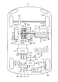
- FIG. 1 is an overall block diagram of a vehicle 1 according to an embodiment.
- vehicle 1 includes an engine 10, a drive shaft 16, a motor generator MG1, a motor generator MG2, a power split device 40, a speed reducer 58, a PCU (Power Control Unit) 60, Battery 70, drive wheel 80, start switch 150, braking device 151, and ECU (Electronic Control Unit) 200 are included.
- PCU Power Control Unit
- the vehicle 1 travels by driving force output from at least one of the engine 10 and the motor generator MG2.
- the power generated by the engine 10 is divided into two paths by the power split device 40.
- One of the two routes is a route transmitted to the drive wheel 80 via the speed reducer 58, and the other route is a route transmitted to the motor generator MG1.
- Motor generator MG1 and motor generator MG2 are, for example, three-phase AC rotating electric machines. Motor generator MG1 and motor generator MG2 are driven by PCU 60.
- the motor generator MG1 has a function as a generator that generates power using the power of the engine 10 divided by the power split device 40 and charges the battery 70 via the PCU 60.
- Motor generator MG1 receives electric power from battery 70 and rotates a crankshaft that is an output shaft of engine 10.
- motor generator MG1 has a function as a starter for starting engine 10.
- Motor generator MG2 has a function as a driving motor that applies driving force to driving wheels 80 using at least one of the electric power stored in battery 70 and the electric power generated by motor generator MG1. Motor generator MG2 also has a function as a generator for charging battery 70 via PCU 60 using electric power generated by regenerative braking.
- the engine 10 is an internal combustion engine such as a gasoline engine or a diesel engine.
- the engine 10 includes a plurality of cylinders 102 and a fuel injection device 104 that supplies fuel to each of the plurality of cylinders 102. Based on the control signal S1 from the ECU 200, the fuel injection device 104 injects an appropriate amount of fuel to each cylinder at an appropriate time, or stops fuel injection to each cylinder.
- the engine 10 is provided with an engine rotation speed sensor 11 for detecting the rotation speed of the crankshaft of the engine 10 (hereinafter referred to as engine rotation speed) Ne.
- the engine rotation speed sensor 11 transmits a signal indicating the detected engine rotation speed Ne to the ECU 200.
- Power split device 40 mechanically connects each of the three elements of drive shaft 16 for rotating drive wheel 80, the output shaft of engine 10 and the rotation shaft of motor generator MG1.
- the power split device 40 enables transmission of power between the other two elements by using any one of the three elements described above as a reaction force element.
- the rotation shaft of motor generator MG2 is connected to drive shaft 16.
- the power split device 40 is a planetary gear mechanism including a sun gear 50, a pinion gear 52, a carrier 54, and a ring gear 56.
- Pinion gear 52 meshes with each of sun gear 50 and ring gear 56.
- the carrier 54 supports the pinion gear 52 so as to be capable of rotating, and is connected to the crankshaft of the engine 10.
- Sun gear 50 is coupled to the rotation shaft of motor generator MG1.
- Ring gear 56 is connected to the rotation shaft of motor generator MG 2 and reduction gear 58 via drive shaft 16.
- Reduction gear 58 transmits power from power split device 40 and motor generator MG2 to drive wheels 80.
- Reduction device 58 transmits reaction force from the road surface received by drive wheels 80 to power split device 40 and motor generator MG2.
- the battery 70 is a power storage device and a rechargeable DC power source.
- a secondary battery such as a nickel metal hydride battery or a lithium ion battery is used.
- the voltage of the battery 70 is about 200V, for example.
- battery 70 is charged using electric power generated by motor generator MG1 and / or motor generator MG2, or may be charged using electric power supplied from an external power source (not shown).
- the battery 70 is not limited to a secondary battery, and may be a battery that can generate a DC voltage, such as a capacitor.
- the battery 70 includes a battery temperature sensor 156 for detecting the battery temperature TB of the battery 70, a current sensor 158 for detecting the current IB of the battery 70, and a voltage sensor 160 for detecting the voltage VB of the battery 70. And are provided.
- the battery temperature sensor 156 transmits a signal indicating the battery temperature TB to the ECU 200.
- Current sensor 158 transmits a signal indicating current IB to ECU 200.
- Voltage sensor 160 transmits a signal indicating voltage VB to ECU 200.
- the start switch 150 is, for example, a push-type switch.
- the start switch 150 may be configured to insert a key into a key cylinder and rotate it to a predetermined position.
- Start switch 150 is connected to ECU 200.
- the start switch 150 transmits a signal ST to the ECU 200.
- the ECU200 judges that it received the start instruction, for example, when signal ST is received when the system of vehicle 1 is a stop state, and makes the system of vehicle 1 shift from a stop state to a start state. Further, when the signal ST is received when the system of the vehicle 1 is in the activated state, the ECU 200 determines that the stop instruction has been received, and shifts the system of the vehicle 1 from the activated state to the stopped state.
- the operation of the start switch 150 by the driver when the system of the vehicle 1 is in the activated state is referred to as an IG off operation, and the driver operates the start switch 150 when the system of the vehicle 1 is in the stopped state.
- the operation is called IG on operation.
- the vehicle 1 becomes operable by supplying power to a plurality of devices necessary for the vehicle 1 to travel.
- the system of the vehicle 1 shifts to the stop state, the supply of power to a part of the plurality of devices necessary for the vehicle 1 to travel is stopped, so that the operation stop state Become.
- the resolver 12 is a rotation speed sensor provided in the motor generator MG1. Resolver 12 detects rotational speed Nm1 of motor generator MG1. The resolver 12 transmits a signal indicating the detected rotation speed Nm1 to the ECU 200.
- the resolver 13 is a rotation speed sensor provided in the motor generator MG2. Resolver 13 detects rotational speed Nm2 of motor generator MG2. The resolver 13 transmits a signal indicating the detected rotation speed Nm2 to the ECU 200.
- the wheel speed sensor 14 detects the rotational speed Nw of the drive wheel 80.
- the wheel speed sensor 14 transmits a signal indicating the detected rotation speed Nw to the ECU 200.
- ECU 200 calculates speed V of vehicle 1 based on the received rotational speed Nw.
- ECU 200 may calculate speed V of vehicle 1 based on rotation speed Nm2 of motor generator MG2 instead of rotation speed Nw.
- Brake pedal 166 is provided in the driver's seat.
- the brake pedal 166 is provided with a brake pedal depression force sensor 168.
- the brake pedal depression force sensor 168 detects the occupant's depression force Pb with respect to the brake pedal 166.
- the brake pedal depression force sensor 168 transmits a signal indicating the detected depression force Pb to the ECU 200.
- the brake pedal depression force sensor 168 may detect the hydraulic pressure in the master cylinder coupled to the brake pedal 166 as the depression force Pb.
- a stroke sensor that detects the depression amount of the brake pedal 166 may be used.
- Accelerator pedal 170 is provided in the driver's seat.
- the accelerator pedal 170 is provided with a pedal stroke sensor 172.
- the pedal stroke sensor 172 detects the stroke amount AP of the accelerator pedal 170.
- the pedal stroke sensor 172 transmits a signal indicating the stroke amount AP to the ECU 200. Based on the stroke amount AP of the accelerator pedal 170, the accelerator opening (%) is calculated.
- an accelerator pedal depression force sensor for detecting the depression force of the occupant on the accelerator pedal 170 may be used.
- the braking device 151 includes a brake actuator 152 and a disc brake 154.
- the disc brake 154 includes a brake disc that rotates integrally with the wheel, and a brake caliper that restricts rotation of the brake disc using hydraulic pressure.
- the brake caliper includes a brake pad provided so as to sandwich the brake disc in a direction parallel to the rotation shaft, and a wheel cylinder for transmitting hydraulic pressure to the brake pad.
- the brake actuator 152 adjusts the hydraulic pressure generated when the driver depresses the brake pedal and the hydraulic pressure generated using a pump, a solenoid valve, and the like, and supplies the hydraulic pressure to the wheel cylinder. Adjust the hydraulic pressure.
- the disc brake 154 is illustrated only on the right side of the rear wheel, but the disc brake 154 is provided for each wheel. A drum brake may be used instead of the disc brake 154.
- the ECU 200 generates a control signal S1 for controlling the engine 10 and outputs the generated control signal S1 to the engine 10.
- ECU 200 also generates a control signal S2 for controlling PCU 60 and outputs the generated control signal S2 to PCU 60.
- ECU 200 generates a control signal S3 for controlling brake actuator 152, and outputs the generated control signal S3 to brake actuator 152.
- the ECU 200 controls the entire hybrid system, that is, the charge / discharge state of the battery 70, the operation state of the engine 10, the motor generator MG1, and the motor generator MG2 so that the vehicle 1 can operate most efficiently by controlling the engine 10, the PCU 60, and the like. Control.
- ECU200 calculates the required driving force corresponding to the amount of depression of an accelerator pedal (not shown) provided in the driver's seat.
- ECU 200 controls the torque of motor generator MG1 and motor generator MG2 and the output of engine 10 in accordance with the calculated required driving force.
- the power split device 40 divides the power of the engine 10 into two paths of power.
- the drive wheel 80 is directly driven by one power. Electric power is generated by driving motor generator MG1 with the other power.
- ECU 200 drives motor generator MG2 using the generated electric power.
- driving assistance of the driving wheel 80 is performed by driving the motor generator MG2.
- the motor generator MG2 that follows the rotation of the drive wheels 80 functions as a generator to perform regenerative braking.
- the electric power recovered by regenerative braking is stored in the battery 70.
- ECU 200 increases the output of engine 10 to increase the motor generator when the state of charge of the power storage device (described in the following description as SOC (State of Charge)) decreases and charging is particularly necessary. Increase the amount of power generated by MG1. As a result, the SOC of the battery 70 increases.
- the ECU 200 may perform control to increase the driving force from the engine 10 as necessary even during low-speed traveling. For example, the battery 70 needs to be charged as described above, an auxiliary machine such as an air conditioner is driven, or the temperature of the cooling water of the engine 10 is raised to a predetermined temperature.
- the ECU 200 determines the input power allowed when the battery 70 is charged based on the battery temperature TB and the current SOC (in the following description, “charging power upper limit value”). Output power (to be described as “discharge power upper limit value Wout” in the following description). For example, when the current SOC decreases, discharge power upper limit Wout is set to be gradually lower. On the other hand, when the current SOC increases, charging power upper limit value Win is set to gradually decrease.
- the secondary battery used as the battery 70 has a temperature dependency that the internal resistance increases at a low temperature. Further, at a high temperature, it is necessary to prevent the temperature from excessively rising due to further heat generation. For this reason, it is preferable to reduce each of the discharge power upper limit value Wout and the charge power upper limit value Win when the battery temperature TB is low and high. ECU 200 sets charge power upper limit value Win and discharge power upper limit value Wout by using, for example, a map or the like according to battery temperature TB and the current SOC.
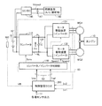
- FIG. 2 is a block diagram showing the configuration of the power supply apparatus including the PCU 60 of FIG. 1 and its periphery.
- the vehicle power supply device shown in FIG. 2 performs drive control of a battery 70 in which a plurality of battery cells are connected in series, a voltage sensor 160 that detects battery voltage VB from battery 70, and motor generators MG1 and MG2. PCU 60 and a portion of ECU 200 that controls PCU 60 (hereinafter referred to as “control device 200”).
- the power supply device for the vehicle further includes a DC / DC converter 146, an auxiliary battery 147, and an auxiliary load 148 including an air conditioner and lighting.
- DC / DC converter 146 steps down the voltage of battery 70 to generate auxiliary machine voltage Vdcout, and supplies auxiliary machine voltage Vdcout to auxiliary battery 147 and auxiliary machine load 148.
- PCU 60 includes a converter 110, a smoothing capacitor 120, motor drive devices 131 and 132 corresponding to motor generators MG1 and MG2, respectively, and a converter / inverter control unit 140.
- motor drive devices 131 and 132 are configured by inverters.
- the motor drive devices 131 and 132 are referred to as inverters 131 and 132.
- Control device 200 determines the required torque for motor generators MG1 and MG2 in consideration of output distribution with engine 10 based on various sensor outputs 17. Further, control device 200 calculates an optimum motor operating voltage according to the operating state of motor generators MG1 and MG2.
- Control device 200 further determines voltage command value Vmr of motor operating voltage Vm and torque command value Tref in motor generators MG1 and MG2 based on the required torque and the optimum motor operating voltage and battery voltage VB from voltage sensor 160. Is generated. Voltage command value Vmr and torque command value Tref are applied to converter / inverter control unit 140.
- Converter / inverter control unit 140 generates converter control signal Scnv for controlling the operation of converter 110 in accordance with voltage command value Vmr from control device 200. Further, converter / inverter control unit 140 generates inverter control signals Spwm1 and Spwm2 for controlling the operations of inverters 131 and 132, respectively, according to torque command value Tref from control device 200.
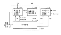
- FIG. 3 is a block diagram showing a control structure in the control device 200 of FIG.
- the control block shown in FIG. 3 is typically realized by the control device 200 executing a program stored in advance, but part or all of the configuration may be realized as dedicated hardware.
- control device 200 includes an HV control unit 250, a battery management lower limit voltage setting unit 252, and a discharge allowable power calculation unit 254.
- the HV control unit 250 sets the travel mode DM of the vehicle 1 that is a hybrid vehicle, and outputs the set travel mode DM to the battery management lower limit voltage setting unit 252.
- HV control unit 250 operates in a mode (hereinafter also referred to as “EV travel mode”) in which the vehicle travels by the output of only motor generator MG2 in accordance with the accelerator opening and wheel speed included in various sensor outputs 17.
- the mode (hereinafter also referred to as “HV traveling mode”) is switched according to the output of engine 10 and motor generator MG2.
- the engine 10 travels only with the output of the motor generator MG2 without using the output of the engine 10.
- the EV travel mode is set. That is, in a region where the accelerator opening is small, vehicle 1 travels with the output of only motor generator MG2. In this case, the operation of the engine 10 is stopped except when the engine start request condition is satisfied.
- the engine 10 is started and set to the HV traveling mode. Thereby, the output from engine 10 is divided into the driving force of driving wheels 80 and the driving force for power generation by motor generator MG1 by power split device 40. Electric power generated by motor generator MG2 is used to drive motor generator MG2. Therefore, during normal travel, drive wheels 80 are driven by the output from engine 10 and the output from motor generator MG2. At this time, the control device 200 controls the power split ratio by the power split device 40 of FIG. 1 so that the overall efficiency is maximized.
- the electric power supplied from the battery 70 is further used for driving the motor generator MG2, and the driving force of the driving wheels 80 further increases.
- motor generator MG2 is driven to rotate by drive wheels 80 to generate electric power.
- the electric power collected by the regenerative power generation of motor generator MG2 is converted into a DC voltage by PCU 60 and used for charging battery 70. Further, when the vehicle is stopped, the engine 10 is automatically stopped.
- the engine 10 is controlled to start when an engine start request condition that requires the engine 10 to start is satisfied.
- the engine start request condition includes a case where a driving force request such as high acceleration is given from the driver. As an example, it includes that the accelerator opening exceeds a predetermined value ⁇ %. Furthermore, a case may be included in which a request unrelated to the driving force request is given, such as when the battery output needs to be charged by the battery 70 or when the engine 10 is warming up.
- the HV control unit 250 cranks and starts the engine 10 by driving the motor generator MG1 as an electric motor by receiving power supplied from the battery 70 as engine start control when the engine start request condition is satisfied. Further, the HV control unit 250 generates an H (logic high) level engine start request signal and outputs it to the battery management lower limit voltage setting unit 252.
- the battery management lower limit voltage setting unit 252 normally sets the management lower limit voltage VB_lim to a predetermined voltage (VBL + Vmg0).
- This predetermined voltage (VBL + Vmg0) is set to the battery lower limit voltage VBL set in advance based on the charge / discharge characteristics of the battery 70 so that the SOC of the battery 70 is not within the proper range and overdischarge may occur.
- the voltage is obtained by adding the initial margin value Vmg0.
- a management lower limit voltage VB_lim of the battery voltage VB is determined separately from the overdischarge management by the SOC.
- Battery management lower limit voltage setting unit 252 sets management lower limit voltage VB_lim more relaxed than a predetermined voltage (VBL + Vmg0) when a predetermined condition is satisfied. As a result, the number of cases where it becomes possible to satisfy the driving request from the driver increases.
- the discharge allowable power calculation unit 254 receives the management lower limit voltage VB_lim from the battery management lower limit voltage setting unit 252 and receives the battery voltage VB from the voltage sensor 160, so that the battery voltage VB does not fall below the management lower limit voltage VB_lim.
- a value Wout is derived.
- the discharge allowable power calculation unit 254 compares the magnitude relationship between the battery voltage VB from the voltage sensor 160 and the management lower limit voltage VB_lim, and the battery voltage VB is compared with the management lower limit voltage VB_lim. Is higher, the discharge power upper limit Wout is derived based on the battery voltage VB. At this time, discharge allowable power calculation unit 254 derives discharge power upper limit Wout based on SOC calculated from battery voltage VB using a known technique. The discharge power upper limit value Wout at this time is a limit value of the discharge power at each time point, which is defined by the chemical reaction limit of the battery 70.
- discharge allowable power calculation unit 254 stores a discharge allowable power map defined in advance using battery voltage VB as a parameter, and derives discharge power upper limit value Wout at each time point based on battery voltage VB.
- the discharge allowable power calculation unit 254 fixes the discharge power upper limit value Wout to a predetermined minimum allowable power (lower limit power). In this way, power limitation of the battery 70 is performed so that the battery voltage VB does not fall below the management lower limit voltage VB_lim.
- the HV control unit 250 sets the travel mode DM of the vehicle 1 in accordance with the various sensor outputs 17, and the motor generators MG ⁇ b> 1 and MG ⁇ b> 2 take into account output distribution with the engine based on the various sensor outputs 17. Determine the required torque. Further, the HV control unit 250 calculates an optimum motor operating voltage according to the determined required torque and the motor rotational speed.
- HV control unit 250 generates voltage command value Vmr of motor operating voltage Vm and torque command value Tref in motor generators MG1 and MG2 based on the required torque and optimum motor operating voltage and discharge power upper limit value Wout. To do.
- the HV control unit 250 calculates the motor power consumption corresponding to the required torque, and determines whether the calculated motor power consumption exceeds the discharge power upper limit value Wout. At this time, if the calculated motor power consumption is equal to or less than the discharge power upper limit value Wout, even if power is consumed by the motor generators MG1 and MG2 according to the required torque, the discharge power upper limit value Wout will not be exceeded.
- the HV control unit 250 sets the torque command value Tref to be equal to the required torque. Further, the HV control unit 250 sets the voltage command value Vmr to be equal to the optimum motor operating voltage.
- the motor power consumption exceeds the discharge power upper limit value Wout
- the motor generators MG1 and MG2 consume power according to the required torque
- the motor power consumption exceeds the discharge power upper limit value Wout. Therefore, in this case, the motor power consumption is limited so as not to exceed the discharge power upper limit value Wout.
- the motor power consumption at the limit where motor power consumption discharge power upper limit value Wout is established, and the torque command value Tref is calculated in correspondence with the calculated motor power consumption. That is, the torque command value Tref is limited to be smaller than the initial required torque Trq. Similarly, voltage command value Vmr is limited to be smaller than the initial optimum motor operating voltage in accordance with the limited required torque Trq.
- Converter / inverter control unit 140 determines the boost ratio in converter 110 (FIG. 2) based on voltage command value Vmr, and generates converter control signal Scnv so that this boost ratio is realized.
- converter / inverter control unit 140 causes inverter control signals in accordance with output values from various sensors so that motor currents that generate torque according to torque command value Tref flow in motor generators MG1 and MG2.
- Spwm1 and Spwm2 are generated.
- inverter control signals Spwm1 and Spwm2 are PWM signal waves generated according to a general control method.
- the output values from the various sensors include, for example, output values from the position sensors and speed sensors of the motor generators MG1 and MG2, output values from the current sensors that detect each phase current, and voltages that detect the motor operating voltage Vm. The output value from the sensor is included.
- FIG. 5 is a diagram for explaining the relationship between the lower limit voltage VBL and the lower limit voltage margin Vmg.
- the lower limit voltage VBL is a lower limit voltage to be observed, which is determined by the temperature used and the performance of the battery. If the battery voltage VB falls below the lower limit voltage VBL, the battery life is adversely affected. Therefore, control is performed so as not to fall below the lower limit voltage VBL.
- a constant margin voltage Vmg is provided by control with respect to the lower limit voltage VBL so that it does not fall below the lower limit voltage VBL in any driving state or surrounding environment, and the voltage is fed back.
- the battery output is limited. Therefore, when the battery voltage VB becomes lower than VBL + Vmg at time t1, the battery voltage VB recovers by limiting the battery output, so that the battery voltage VB as shown by the broken line at time t2 falls below the lower limit voltage VBL. Can be avoided.
- the initial value Vmg0 of the voltage margin is such that a steep power demand (for example, when an acceleration request is generated and power is consumed by MG2, further power is consumed by cranking by MG1 at engine start-up).
- a steep power demand for example, when an acceleration request is generated and power is consumed by MG2, further power is consumed by cranking by MG1 at engine start-up.
- VBL lower limit voltage
- the motor generator MG2 is designed to avoid applying a heavy load to the engine until the warming up of the catalyst is completed after the engine is started with the output from the engine lowered as much as possible. There is a case where the vehicle is driven by the torque of. If the battery output is limited in such a case, a case where the driver's acceleration request or the like cannot be satisfied may occur.
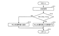
- step S2 it is determined in step S2 whether the engine is operating. If the engine is already in operation, no cranking is generated by the motor generator MG1 when the engine is started, so that a steep power demand does not occur. In such a case, it is possible to travel with good responsiveness that exhibits battery performance without limiting unnecessary battery output.
- step S2 when the engine is not in operation, there is a possibility that cranking by the motor generator MG1 may occur in order to start the engine, so a margin is required for the voltage margin Vmg. Therefore, the process returns to step S1, and an initial value is set for the lower limit voltage margin Vmg.
- step S3 it is determined whether or not the battery voltage VB is higher than a predetermined value.
- the predetermined value is, for example, lower limit voltage VBL + Vg, and voltage Vg can be set to 3 V, for example. If the battery voltage VB has already dropped to the vicinity of the lower limit voltage VBL, the battery voltage VB may reach the lower limit voltage VBL as soon as the battery output limit is relaxed. This is because it is not appropriate to decrease the value.
- step S3 If VB> VBL + Vg is not satisfied in step S3, the process returns to step S2. If VB> VBL + Vg is satisfied in step S3, the process proceeds to step S4.
- step S4 it is determined whether or not ⁇ VB / ⁇ t is equal to or smaller than a threshold value. If the battery voltage VB decreases slowly, the lower limit voltage margin Vmg may be reduced. However, if the battery voltage VB decreases sharply, reducing the lower limit voltage margin Vmg limits the battery output. This is because there is a possibility that the battery voltage VB reaches the lower limit voltage VBL due to a time delay until the battery is charged or a response delay of the battery.
- step S4 If the magnitude of ⁇ VB / ⁇ t is not less than or equal to the threshold value in step S4, the process returns to step S2. If the magnitude of ⁇ VB / ⁇ t is less than or equal to the threshold value in step S4, the process proceeds to step S5.
- step S5 the lower limit voltage margin Vmg is set with reference to the lower limit voltage margin setting map.
- the lower limit voltage VB_lim used for control is output from the battery management lower limit voltage setting unit 252 of FIG. 3 to the discharge allowable power calculation unit 254.
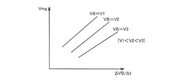
- FIG. 6 is a diagram showing an example of a lower limit voltage margin setting map used in step S5 of FIG.
- FIG. 7 is a diagram showing an example of the lower limit voltage margin setting map used in step S5 of FIG. 4 in an expression different from FIG.
- the corresponding lower limit voltage margin Vmg is determined.
- the lower limit voltage margin Vmg increases as the magnitude of change ⁇ VB / ⁇ t in the battery voltage increases. This is because a large margin is required at the time of steep change in order to keep the lower limit voltage VBL.
- the lower limit voltage margin Vmg increases as the battery voltage VB decreases. This is because if the battery voltage VB is low, it is close to the lower limit voltage VBL, so that it is desirable that the lower limit voltage margin Vmg is large in order to reliably keep the lower limit voltage VBL.
- FIG. 8 is a flowchart for explaining the control executed by the discharge allowable power calculation unit 254 of FIG. The processing of this flowchart is called up and executed every time a predetermined time elapses or a predetermined condition is satisfied from a predetermined main routine.
- discharge allowable power calculation unit 254 acquires battery voltage VB in step S11.
- step S12 it is determined whether or not battery voltage VB is lower than a threshold value.
- the threshold value here is set to a value obtained by adding the lower limit voltage margin Vmg determined in the flowchart of FIG. 4 to the battery lower limit voltage VBL to be protected.
- step S12 if VB ⁇ VBL + Vmg is not satisfied, the process proceeds to step S13, and the discharge power upper limit value Wout is set to a normal value.
- This normal value is a battery output upper limit determined based on SOC, battery temperature, and the like.
- step S12 if VB ⁇ VBL + Vmg is established in step S12, the process proceeds to step S13, and the discharge power upper limit Wout is limited to a value lower than the normal value.
- the discharge power upper limit value Wout By limiting the discharge power upper limit value Wout to a value lower than the normal value, the battery voltage VB can be prevented from falling below the lower limit voltage VBL.
- step S13 When the discharge power upper limit Wout is determined in step S13 or step S14, the process proceeds to step S15 and the control is moved to the main routine.
- FIG. 9 is a diagram showing an example of changes in battery voltage and battery power when control is performed by the control method of the present embodiment.
- the initial value Vmg0 is 10V.
- the discharge power upper limit Wout is limited when the battery voltage VB reaches VBL + Vmg0 at time t12.
- battery power PB is limited as shown by line W1A, and battery voltage VB stops dropping near VBL + Vmg0 as shown by line W2A.
- vehicle 1 which uses the drive wheel 80 as a front wheel was shown as an example, it is not limited to such a drive system in particular.
- vehicle 1 may have a rear wheel as a driving wheel.
- vehicle 1 may be a vehicle in which motor generator MG2 in FIG. 1 is omitted.
- vehicle 1 may be a vehicle in which motor generator MG2 in FIG. 1 is coupled to a drive shaft for driving rear wheels instead of front wheel drive shaft 16.
- a transmission may be provided between drive shaft 16 and speed reducer 58 or between drive shaft 16 and motor generator MG2.
- FIG. 10 is a diagram illustrating a configuration of an example of a modification of the vehicle.
- vehicle 1 ⁇ / b> A as a modified example does not have motor generator MG ⁇ b> 2 compared to the configuration of vehicle 1 in FIG. 1, and the rotation shaft of motor generator MG ⁇ b> 1 is directly connected to the output shaft of engine 10.
- the power transmission device 42 having the clutch 22 is included instead of the power split device 40 and that the clutch 18 is further provided between the engine 10 and the motor generator MG1.
- Clutch 22 changes motor generator MG1 and drive wheel 80 between a power transmission state and a power cutoff state.
- the power transmission device 42 is, for example, a transmission.
- Vehicle 1 or 1A shown in FIG. 1 or FIG. 10 supplies engine 10, motor generator MG ⁇ b> 1 or MG for starting engine 10, PCU 60 for operating motor generator MG ⁇ b> 1 or MG, and power supply to PCU 60.
- a control device 200 that controls the PCU 60 so that the voltage of the battery 70 does not fall below a lower limit value.
- Control device 200 sets the lower limit value to a lower value when the change condition including that engine 10 is in operation (step S2 in FIG. 4) is satisfied as compared to when engine 10 is stopped.
- the change condition further includes that the magnitude of the voltage change of the battery 70 is not more than the first threshold value (step S4 in FIG. 4) in addition to the engine 10 being in operation.
- the change condition is that the voltage of the battery 70 is lower than the second threshold in addition to the engine 10 being in operation and the magnitude of the voltage change of the battery 70 being equal to or lower than the first threshold. (Step S3 in FIG. 4).
- the vehicle 1 further includes a motor generator MG ⁇ b> 2 that is driven by the PCU 60 and generates propulsion torque of the vehicle.
- a motor generator MG ⁇ b> 2 that is driven by the PCU 60 and generates propulsion torque of the vehicle.
- the motor generator MG1 receives power from the engine 10 as necessary to generate power.
- vehicle 1 further includes a power split device 40 connected to the respective rotation shafts of motor generator MG1, motor generator MG2 and engine 10.
- motor generator MG shown in FIG. 10 generates propulsion torque for the vehicle, and generates torque for starting engine 10 as necessary.
- vehicle 1A includes a clutch 18 provided between the rotation shaft of engine 10 and the rotation shaft of motor generator MG, and a power transmission device 42 provided between motor generator MG and the drive shaft. Further prepare.
- the present invention can be applied to a hybrid vehicle as long as a motor and an engine for starting the engine are mounted.
- 1,1A vehicle 10 engine, 11 engine rotation speed sensor, 12, 13 resolver, 14 wheel speed sensor, 16 drive shaft, 18, 22 clutch, 40 power split device, 42 power transmission device, 50 sun gear, 52 pinion gear, 54 Carrier, 56 ring gear, 58 speed reducer, 70 battery, 80 drive wheel, 102 cylinder, 104 fuel injection device, 110 converter, 120 smoothing capacitor, 131, 132 motor drive device, 131, 132 inverter, 140 inverter control unit, 150 start Switch, 151 brake device, 152 brake actuator, 154 disc brake, 156 battery temperature sensor, 158 current sensor, 160 voltage sensor, 166 brake pedal, 168 brake Pedal force sensor, 170 an accelerator pedal, 172 pedal stroke sensor, 200 control unit, 250 control unit, 252 battery management lower limit voltage setting unit, 254 discharge allowable power calculation unit, MG1, MG2 motor-generator.
Landscapes
- Engineering & Computer Science (AREA)
- Mechanical Engineering (AREA)
- Transportation (AREA)
- Power Engineering (AREA)
- Combustion & Propulsion (AREA)
- Chemical & Material Sciences (AREA)
- Sustainable Energy (AREA)
- Sustainable Development (AREA)
- Life Sciences & Earth Sciences (AREA)
- Automation & Control Theory (AREA)
- General Engineering & Computer Science (AREA)
- Electric Propulsion And Braking For Vehicles (AREA)
- Hybrid Electric Vehicles (AREA)
- Secondary Cells (AREA)
Priority Applications (5)
| Application Number | Priority Date | Filing Date | Title |
|---|---|---|---|
| US14/232,787 US9145131B2 (en) | 2011-08-04 | 2011-08-04 | Vehicle and vehicle control method |
| CN201180072569.3A CN103702881B (zh) | 2011-08-04 | 2011-08-04 | 车辆和车辆的控制方法 |
| PCT/JP2011/067840 WO2013018221A1 (ja) | 2011-08-04 | 2011-08-04 | 車両および車両の制御方法 |
| JP2013526700A JP5729475B2 (ja) | 2011-08-04 | 2011-08-04 | 車両および車両の制御方法 |
| EP11870294.3A EP2740644B1 (de) | 2011-08-04 | 2011-08-04 | Fahrzeug und fahrzeugsteuerungsverfahren |
Applications Claiming Priority (1)
| Application Number | Priority Date | Filing Date | Title |
|---|---|---|---|
| PCT/JP2011/067840 WO2013018221A1 (ja) | 2011-08-04 | 2011-08-04 | 車両および車両の制御方法 |
Publications (1)
| Publication Number | Publication Date |
|---|---|
| WO2013018221A1 true WO2013018221A1 (ja) | 2013-02-07 |
Family
ID=47628783
Family Applications (1)
| Application Number | Title | Priority Date | Filing Date |
|---|---|---|---|
| PCT/JP2011/067840 WO2013018221A1 (ja) | 2011-08-04 | 2011-08-04 | 車両および車両の制御方法 |
Country Status (5)
| Country | Link |
|---|---|
| US (1) | US9145131B2 (de) |
| EP (1) | EP2740644B1 (de) |
| JP (1) | JP5729475B2 (de) |
| CN (1) | CN103702881B (de) |
| WO (1) | WO2013018221A1 (de) |
Cited By (4)
| Publication number | Priority date | Publication date | Assignee | Title |
|---|---|---|---|---|
| JP2016078750A (ja) * | 2014-10-21 | 2016-05-16 | 株式会社豊田自動織機 | 車両の制御装置 |
| KR20170056301A (ko) * | 2015-11-13 | 2017-05-23 | 주식회사 엘지화학 | 이차 전지의 출력 파라미터를 조정하는 시스템 및 그 방법 |
| JP2017204953A (ja) * | 2016-05-12 | 2017-11-16 | 株式会社デンソー | 回転電機ユニット |
| JP2017202778A (ja) * | 2016-05-12 | 2017-11-16 | 株式会社デンソー | 回転電機の制御装置 |
Families Citing this family (5)
| Publication number | Priority date | Publication date | Assignee | Title |
|---|---|---|---|---|
| CN103847530B (zh) | 2012-12-03 | 2017-04-12 | 通用电气公司 | 电驱动系统及其能量管理方法 |
| JP6277975B2 (ja) * | 2015-02-26 | 2018-02-14 | トヨタ自動車株式会社 | アイドリングストップ制御装置 |
| US10618512B2 (en) * | 2017-08-04 | 2020-04-14 | Toyota Motor Engineering & Manufacturing North America, Inc. | Expanding electric vehicle mode during downhill grade conditions |
| CN112440744B (zh) * | 2019-08-29 | 2022-05-17 | 北京新能源汽车股份有限公司 | 一种蓄电池电量管理的控制方法、整车控制器及管理系统 |
| US11865944B2 (en) | 2020-05-29 | 2024-01-09 | Deltran Operations Usa, Inc. | Battery management system for batteries in engine start and deep cycle applications |
Citations (10)
| Publication number | Priority date | Publication date | Assignee | Title |
|---|---|---|---|---|
| JP2000134719A (ja) | 1998-10-29 | 2000-05-12 | Isuzu Motors Ltd | パラレル・ハイブリッド電気自動車のバッテリ充電制御装置 |
| JP2002017001A (ja) | 2000-06-30 | 2002-01-18 | Okamura Kenkyusho:Kk | ハイブリット電気自動車における蓄電装置の充電制御方法 |
| JP2002051405A (ja) | 2000-07-31 | 2002-02-15 | Sanyo Electric Co Ltd | ハイブリッド電気自動車 |
| JP2005045883A (ja) * | 2003-07-24 | 2005-02-17 | Honda Motor Co Ltd | ハイブリット車両 |
| JP2006211789A (ja) * | 2005-01-26 | 2006-08-10 | Toyota Motor Corp | 動力出力装置およびこれを搭載する自動車並びに動力出力装置の制御方法 |
| JP2007162657A (ja) | 2005-12-16 | 2007-06-28 | Panasonic Ev Energy Co Ltd | 二次電池用の制御装置及び二次電池の出力制御方法 |
| JP2008254603A (ja) * | 2007-04-05 | 2008-10-23 | Toyota Motor Corp | 車両およびその制御方法 |
| JP2010089719A (ja) * | 2008-10-10 | 2010-04-22 | Toyota Motor Corp | ハイブリッド車両の電源システム |
| JP2010183785A (ja) | 2009-02-06 | 2010-08-19 | Nissan Motor Co Ltd | バッテリ充電制御装置及びバッテリ充電制御方法 |
| JP2010268578A (ja) * | 2009-05-13 | 2010-11-25 | Toyota Motor Corp | 昇降圧コンバータの制御装置およびこれを搭載するハイブリッド車並びに昇降圧コンバータの制御方法 |
Family Cites Families (12)
| Publication number | Priority date | Publication date | Assignee | Title |
|---|---|---|---|---|
| JP3534010B2 (ja) * | 1999-09-24 | 2004-06-07 | 株式会社日立製作所 | 自動車の電源装置 |
| JP3613216B2 (ja) * | 2001-09-18 | 2005-01-26 | 日産自動車株式会社 | ハイブリッド車両の制御装置 |
| CN1311999C (zh) * | 2005-01-31 | 2007-04-25 | 上海汽车工业(集团)总公司汽车工程研究院 | 并联式混合动力驱动系统及其驱动方法 |
| JP5050325B2 (ja) * | 2005-07-12 | 2012-10-17 | 日産自動車株式会社 | 組電池用制御装置 |
| JP4618158B2 (ja) * | 2006-02-23 | 2011-01-26 | トヨタ自動車株式会社 | ハイブリッド車両 |
| JP4779943B2 (ja) * | 2006-11-20 | 2011-09-28 | 日産自動車株式会社 | ハイブリッド車両 |
| JP4992728B2 (ja) * | 2008-01-10 | 2012-08-08 | トヨタ自動車株式会社 | 電源装置およびその放電制御方法 |
| JP2010090726A (ja) * | 2008-10-03 | 2010-04-22 | Nissan Motor Co Ltd | 二次電池制御装置および二次電池制御方法 |
| JP4919120B2 (ja) * | 2009-03-03 | 2012-04-18 | 株式会社デンソー | バッテリの状態検出装置 |
| CN102458906B (zh) * | 2009-06-10 | 2014-03-12 | 丰田自动车株式会社 | 混合动力车辆及其控制方法 |
| WO2011125187A1 (ja) * | 2010-04-07 | 2011-10-13 | トヨタ自動車株式会社 | ハイブリッド車両の制御装置およびそれを備えるハイブリッド車両 |
| JP5400697B2 (ja) * | 2010-04-28 | 2014-01-29 | トヨタ自動車株式会社 | ハイブリッド車両の制御装置およびそれを備えるハイブリッド車両 |
-
2011
- 2011-08-04 WO PCT/JP2011/067840 patent/WO2013018221A1/ja active Application Filing
- 2011-08-04 JP JP2013526700A patent/JP5729475B2/ja active Active
- 2011-08-04 US US14/232,787 patent/US9145131B2/en active Active
- 2011-08-04 EP EP11870294.3A patent/EP2740644B1/de active Active
- 2011-08-04 CN CN201180072569.3A patent/CN103702881B/zh active Active
Patent Citations (10)
| Publication number | Priority date | Publication date | Assignee | Title |
|---|---|---|---|---|
| JP2000134719A (ja) | 1998-10-29 | 2000-05-12 | Isuzu Motors Ltd | パラレル・ハイブリッド電気自動車のバッテリ充電制御装置 |
| JP2002017001A (ja) | 2000-06-30 | 2002-01-18 | Okamura Kenkyusho:Kk | ハイブリット電気自動車における蓄電装置の充電制御方法 |
| JP2002051405A (ja) | 2000-07-31 | 2002-02-15 | Sanyo Electric Co Ltd | ハイブリッド電気自動車 |
| JP2005045883A (ja) * | 2003-07-24 | 2005-02-17 | Honda Motor Co Ltd | ハイブリット車両 |
| JP2006211789A (ja) * | 2005-01-26 | 2006-08-10 | Toyota Motor Corp | 動力出力装置およびこれを搭載する自動車並びに動力出力装置の制御方法 |
| JP2007162657A (ja) | 2005-12-16 | 2007-06-28 | Panasonic Ev Energy Co Ltd | 二次電池用の制御装置及び二次電池の出力制御方法 |
| JP2008254603A (ja) * | 2007-04-05 | 2008-10-23 | Toyota Motor Corp | 車両およびその制御方法 |
| JP2010089719A (ja) * | 2008-10-10 | 2010-04-22 | Toyota Motor Corp | ハイブリッド車両の電源システム |
| JP2010183785A (ja) | 2009-02-06 | 2010-08-19 | Nissan Motor Co Ltd | バッテリ充電制御装置及びバッテリ充電制御方法 |
| JP2010268578A (ja) * | 2009-05-13 | 2010-11-25 | Toyota Motor Corp | 昇降圧コンバータの制御装置およびこれを搭載するハイブリッド車並びに昇降圧コンバータの制御方法 |
Cited By (6)
| Publication number | Priority date | Publication date | Assignee | Title |
|---|---|---|---|---|
| JP2016078750A (ja) * | 2014-10-21 | 2016-05-16 | 株式会社豊田自動織機 | 車両の制御装置 |
| KR20170056301A (ko) * | 2015-11-13 | 2017-05-23 | 주식회사 엘지화학 | 이차 전지의 출력 파라미터를 조정하는 시스템 및 그 방법 |
| JP2018533338A (ja) * | 2015-11-13 | 2018-11-08 | エルジー・ケム・リミテッド | 二次電池の出力パラメータを調整するシステム及びその方法 |
| KR102014451B1 (ko) | 2015-11-13 | 2019-08-26 | 주식회사 엘지화학 | 이차 전지의 출력 파라미터를 조정하는 시스템 및 그 방법 |
| JP2017204953A (ja) * | 2016-05-12 | 2017-11-16 | 株式会社デンソー | 回転電機ユニット |
| JP2017202778A (ja) * | 2016-05-12 | 2017-11-16 | 株式会社デンソー | 回転電機の制御装置 |
Also Published As
| Publication number | Publication date |
|---|---|
| EP2740644A1 (de) | 2014-06-11 |
| US9145131B2 (en) | 2015-09-29 |
| EP2740644A4 (de) | 2016-11-16 |
| US20140163800A1 (en) | 2014-06-12 |
| JP5729475B2 (ja) | 2015-06-03 |
| JPWO2013018221A1 (ja) | 2015-03-05 |
| EP2740644B1 (de) | 2019-11-27 |
| CN103702881B (zh) | 2016-05-11 |
| CN103702881A (zh) | 2014-04-02 |
Similar Documents
| Publication | Publication Date | Title |
|---|---|---|
| JP5729475B2 (ja) | 車両および車両の制御方法 | |
| JP4992728B2 (ja) | 電源装置およびその放電制御方法 | |
| JP5725037B2 (ja) | 車両および車両用制御方法 | |
| JP5267734B2 (ja) | 電動車両およびその制御方法 | |
| JP5598555B2 (ja) | 車両および車両用制御方法 | |
| JP5652479B2 (ja) | 車両および車両用制御方法 | |
| JP2010058579A (ja) | ハイブリッド車両 | |
| JP2006312352A (ja) | 駆動システムの制御装置 | |
| JP6028328B2 (ja) | ハイブリッド車両 | |
| JP5644868B2 (ja) | 車両および車両の制御方法 | |
| KR101518898B1 (ko) | 플러그인 하이브리드 자동차의 충전지향모드 제어장치 및 방법 | |
| JP2006144589A (ja) | ハイブリッド車のエンジン制御装置 | |
| JP5652546B2 (ja) | 車両および車両用制御方法 | |
| JP2012162097A (ja) | 車両 | |
| JP3704996B2 (ja) | ハイブリッド車両の制御装置 | |
| JP2012224304A (ja) | 車両の制振制御装置 | |
| JP5810580B2 (ja) | 車両および車両用制御方法 | |
| JP2012180066A (ja) | 電動車両 | |
| WO2012105019A1 (ja) | 車両および車両の制御方法 | |
| JP5700053B2 (ja) | 車両および車両用制御方法 | |
| JP2015013517A (ja) | 車両の制御装置 | |
| JP2012196007A (ja) | 電気自動車 | |
| WO2014038442A1 (ja) | ハイブリッド車両の制御装置 | |
| JP2013112320A (ja) | ハイブリッド車両 | |
| JP2012236470A (ja) | 車両の制振制御装置 |
Legal Events
| Date | Code | Title | Description |
|---|---|---|---|
| WWE | Wipo information: entry into national phase |
Ref document number: 201180072569.3 Country of ref document: CN |
|
| 121 | Ep: the epo has been informed by wipo that ep was designated in this application |
Ref document number: 11870294 Country of ref document: EP Kind code of ref document: A1 |
|
| ENP | Entry into the national phase |
Ref document number: 2013526700 Country of ref document: JP Kind code of ref document: A |
|
| WWE | Wipo information: entry into national phase |
Ref document number: 14232787 Country of ref document: US |
|
| WWE | Wipo information: entry into national phase |
Ref document number: 2011870294 Country of ref document: EP |
|
| NENP | Non-entry into the national phase |
Ref country code: DE |